Pre-LAB 6 Preparation: Fundamentals of Circuits IV: Kirchhoff's ...
Pre-LAB 6 Preparation: Fundamentals of Circuits IV: Kirchhoff's ...
Pre-LAB 6 Preparation: Fundamentals of Circuits IV: Kirchhoff's ...
- No tags were found...

Create successful ePaper yourself
Turn your PDF publications into a flip-book with our unique Google optimized e-Paper software.
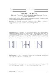
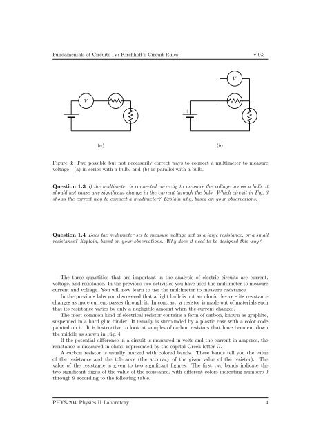
<strong>Fundamentals</strong> <strong>of</strong> <strong>Circuits</strong> <strong>IV</strong>: Kirchh<strong>of</strong>f’s Circuit Rules v 0.3VV+−+−(a)(b)Figure 3: Two possible but not necessarily correct ways to connect a multimeter to measurevoltage - (a) in series with a bulb, and (b) in parallel with a bulb.Question 1.3 If the multimeter is connected correctly to measure the voltage across a bulb, itshould not cause any significant change in the current through the bulb. Which circuit in Fig. 3shows the correct way to connect a multimeter? Explain why, based on your observations.Question 1.4 Does the multimeter set to measure voltage act as a large resistance, or a smallresistance? Explain, based on your observations. Why does it need to be designed this way?The three quantities that are important in the analysis <strong>of</strong> electric circuits are current,voltage, and resistance. In the previous two activities you have used the multimeter to measurecurrent and voltage. You will now learn to use the multimeter to measure resistance.In the previous labs you discovered that a light bulb is not an ohmic device - its resistancechanges as more current passes through it. In contrast, a resistor is made out <strong>of</strong> materials suchthat its resistance varies by only a negligible amount when the current changes.The most common kind <strong>of</strong> electrical resistor contains a form <strong>of</strong> carbon, known as graphite,suspended in a hard glue binder. It usually is surrounded by a plastic case with a color codepainted on it. It is instructive to look at samples <strong>of</strong> carbon resistors that have been cut downthe middle as shown in Fig. 4.If the potential difference in a circuit is measured in volts and the current in amperes, theresistance is measured in ohms, represented by the capital Greek letter Ω.A carbon resistor is usually marked with colored bands. These bands tell you the value<strong>of</strong> the resistance and the tolerance (the accuracy <strong>of</strong> the given value <strong>of</strong> the resistor). Thevalue <strong>of</strong> the resistance is given to two significant figures. The first two bands indicate thetwo significant digits <strong>of</strong> the value <strong>of</strong> the resistance, with different colors indicating numbers 0through 9 according to the following table.PHYS-204:Physics II Laboratory 4