Lab & Pre-lab #11
Lab & Pre-lab #11
Lab & Pre-lab #11

Create successful ePaper yourself
Turn your PDF publications into a flip-book with our unique Google optimized e-Paper software.
Name:<br />
<strong>Lab</strong> Partners:<br />
Date:<br />
<strong>Pre</strong>-<strong>Lab</strong> Assignment:<br />
Lenses and Images<br />
(Due at the beginning of <strong>lab</strong>)<br />
Directions: Read over the <strong>lab</strong> handout and then answer the following questions about the<br />
procedures.<br />
Question 1 What is your prediction 1.1<br />
Question 2 The relation between the position of the image and object for a thin lens is given<br />
by the thin lens equation:<br />
1<br />
d 0<br />
+ 1 d i<br />
= 1 f<br />
where f is the focal length of the lens. Using the fact that 1 divided by a very large number is<br />
nearly 0, show that the thin lens equation predicts that an object located at the focal point gives<br />
an image that is infinitely far away, that is, when d i is very large, d o = f.<br />
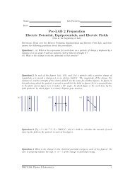
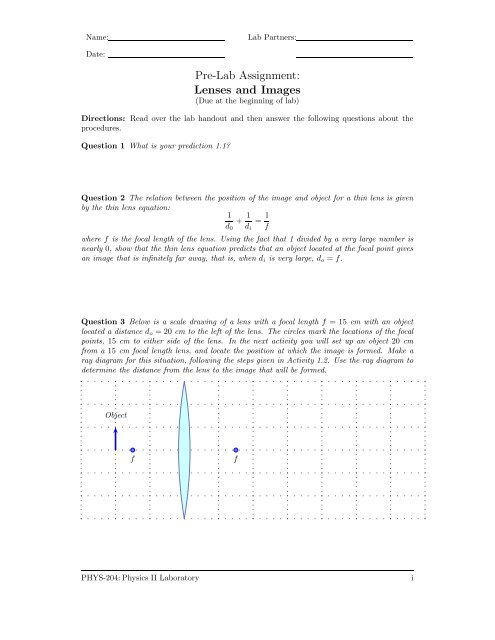
Question 3 Below is a scale drawing of a lens with a focal length f = 15 cm with an object<br />
located a distance d o = 20 cm to the left of the lens. The circles mark the locations of the focal<br />
points, 15 cm to either side of the lens. In the next activity you will set up an object 20 cm<br />
from a 15 cm focal length lens, and locate the position at which the image is formed. Make a<br />
ray diagram for this situation, following the steps given in Activity 1.2. Use the ray diagram to<br />
determine the distance from the lens to the image that will be formed.<br />
Object<br />
f<br />
f<br />
PHYS-204: Physics II <strong>Lab</strong>oratory<br />
i
Name:<br />
<strong>Lab</strong> Partners:<br />
Date:<br />
Lenses and Images<br />
Objectives<br />
• To understand what is meant by the focal point of a lens.<br />
• To understand the relationship between the object distance, the image distance and the<br />
focal length of a lens.<br />
• To understand the types of images formed by a lens.<br />
Overview<br />
Lenses are used in many devices that we use everyday-they are essential for the operation of<br />
cameras and projectors. Lenses are needed for devices such as microscopes to magnify small<br />
objects so that we can see them.<br />
In the previous <strong>lab</strong> you studied the refraction of light rays by lenses. In this experiment we<br />
will continue this investigation by observing images formed by lenses in various arrangements,<br />
and determining how the positions and sizes of these images are related to the positions and<br />
sizes of the object.<br />
These <strong>lab</strong>s have been adapted from the Real Time Physics Active Learning <strong>Lab</strong>oratories [1].<br />
The goals, guiding principles and procedures of these <strong>lab</strong>s closely parallel the implementations<br />
found in the work of those authors [1, 2, 3].<br />
Investigation 1:<br />
Images formed by a convex lens<br />
Every lens has two focal points. The importance of these points is that all light rays reaching<br />
the lens coming from a very distant object (ideally, infinitely far away) will be focused at a<br />
focal point, as in Fig. 1.<br />
The focal length is the distance from the center of the lens to a focal point. The focal length<br />
depends on how the lens is made. The curvature of the surfaces of the lens determines the focal<br />
length.<br />
<strong>Pre</strong>diction 1.1 Will a lens whose surfaces have very little curvature have a smaller or larger<br />
focal length than one for which the surfaces have greater curvature<br />
To carry out this activity, you will need the following:<br />
• One 15 cm focal length convex lens.<br />
• One 30 cm focal length convex lens.<br />
• optical bench.<br />
PHYS-204: Physics II <strong>Lab</strong>oratory 1
Lenses and Images v 0.1<br />
Focal Point<br />
f<br />
f<br />
Focal Length<br />
Figure 1: Parallel light rays converge at the focal point.<br />
• light source.<br />
• F-diaphragm.<br />
• lens holders.<br />
• white projection screen.<br />
• meter stick.<br />
Activity 1.1: Focal Lengths of Convex Lenses<br />
Step 1: Examine the two convex lenses. The lenses have their focal length marked on them.<br />
One should have a focal length of +15 cm, the other +30 cm. Note which has the more<br />
sharply curved surfaces..<br />
Question 1.1 To make a lens with shorter focal length, should the surfaces have greater<br />
or less curvature than for a longer focal length lens Which lens would you say a lens is<br />
more “powerful” if it has a shorter focal length, or a longer focal length<br />
Light rays which start from an object located at the focal point follow the paths shown<br />
in Fig. 1, but in the reverse direction. These rays diverge from the focal point, enter the<br />
lens and come out of the lens parallel to each other. This situation is depicted in Fig. 2.<br />
Step 2: Mount the light source and F-diaphragm at one end of your optical bench. The F-<br />
diaphragm should be right up against the light source, as in Fig. 3. This F-diaphragm<br />
provides the ”object in each of our optical systems.<br />
PHYS-204: Physics II <strong>Lab</strong>oratory 2
Lenses and Images v 0.1<br />
Light Source<br />
at Focal Point<br />
f<br />
Focal Length<br />
Figure 2: Light rays starting at the focal point come out parallel<br />
lamp<br />
Figure 3: Arrangement of light source, F-diaphragm, and lens.<br />
Step 3: Mount the 15 cm lens on the optical bench using a lens holder. Do not tighten the<br />
mounting screw on the holder-leave it loose so that you can slide the lens back and forth.<br />
Step 4: Turn the optical bench so that the light is directed towards the wall on the far side of<br />
the room. The distance to the other side of the room is very large compared to the focal<br />
length, so this can be considered to be essentially infinity.<br />
Step 5: Turn on the light source, and slide the lens holder back and forth until a sharp image<br />
is formed on the opposite wall. When you have a sharp image formed far away, the object<br />
must be located at the focal point. Thus the distance from the lens to the F-diaphragm<br />
should be just the focal length. Measure this distance with the meter stick, and record it<br />
as the measured focal length below. Also record the focal length marked on the lens.<br />
Measured focal length cm. Marked focal length cm<br />
Question 1.2 Does your measured focal length agree with the value marked on the lens.<br />
PHYS-204: Physics II <strong>Lab</strong>oratory 3
Lenses and Images v 0.1<br />
Step 6: Replace the 15 cm lens with the 30 cm lens. Again adjust the position of the lens<br />
to get a clear image on the opposite wall. Measure the distance from the lens to the<br />
F-diaphragm, and record it, together with the value of the focal length marked on the<br />
lens.<br />
Measured focal length cm. Marked focal length cm<br />
Question 1.3 Does your measured focal length agree with the value marked on the lens.<br />
Image<br />
Object<br />
f<br />
f<br />
Figure 4: Many light rays converging at one point to form an image.<br />
Activity 1.2:<br />
Locating an Image Using a Ray Diagram<br />
We will now examine what determines the location of an image formed by the lens when the<br />
object is not at the focal point. Recall from last week’s <strong>lab</strong> how an image is formed. The lens<br />
deflects the rays of light that come from one point in the object so that they converge and all<br />
cross at some point. That point is where the image is formed, as in Fig. 4. Out of all these<br />
rays, there are three whose paths are easy to determine. These are shown in Fig. 5. To locate<br />
these rays it is only necessary to know the locations of the object, lens, and focal points. You<br />
should do this activity before coming to the <strong>lab</strong>, as part of the pre-<strong>lab</strong> assignment.<br />
Fig. 6 is a scale drawing of a lens with a focal length f = 15cm with an object located a<br />
distance do = 20cm to the left of the lens. The circles mark the locations of the focal points,<br />
15cm to either side of the lens. In the next activity you will set up an object 20cm from a 15cm<br />
focal length lens, and locate the position at which the image is formed.<br />
Step 1: Use a ruler with a centimeter scale to measure the distance between from one focal<br />
point to the other in Fig. 6 of your <strong>lab</strong> handout. Using the fact the these two points<br />
represent points which are actually 30cm apart, work out the scale of the drawing - that<br />
PHYS-204: Physics II <strong>Lab</strong>oratory 4
Lenses and Images v 0.1<br />
a<br />
b<br />
Image<br />
Object<br />
f<br />
f<br />
c<br />
Figure 5: The Principle rays that are sufficient to locate an image. Ray (a) starts parallel to<br />
the axis and is deflected through the opposite focal point. Ray (b) Goes through the center of<br />
the lens where it is not deflected. Ray (c) goes from the object through the first focal point,<br />
and is then deflected so that it emerges parallel to the axis. The tip of the arrow of the image<br />
is located where these rays cross. Any two of these three are sufficient to find the location of<br />
the image.<br />
is the number of centimeters in the actual physical arrangement corresponds to 1cm in<br />
the drawing.<br />
Scale factor: cm per 1 cm in the drawing.<br />
Step 2: Draw two of the principle rays on the scale drawing (use a ruler to make sure they are<br />
straight and go through the right points). Draw an arrow corresponding to the image,<br />
with the tip of the arrow located where the rays cross. You should then draw the third<br />
principle ray - it should intersect the others right at the tip of the arrow. If it is way off,<br />
try redoing your drawing more carefully.<br />
Step 3: Measure the distance from the center of the lens to the image of the arrow on your<br />
drawing. Using the scale factor you determined in step 1, convert this to the actual<br />
distance from the lens that the image will be formed.<br />
Measured distance to image in the ray diagram<br />
cm<br />
Actual distance to the image (previous answer times the scale factor):<br />
d i =<br />
cm<br />
Step 4: Measure the height of the image and the object, and record them. Then calculate<br />
their ratio, h i /h o . Then calculate the ratio of the image and object distances, d i /d o .<br />
h i = cm h o = cm<br />
h i /h o = d i /d o =<br />
PHYS-204: Physics II <strong>Lab</strong>oratory 5
Lenses and Images v 0.1<br />
Object<br />
f<br />
f<br />
Figure 6: Scale drawing with f = 15 cm, and d o = 20 cm.<br />
Question 1.4 Is the ratio of the heights of the image and object nearly equal to the ratio of<br />
their distances Identify triangles in your ray diagram that show that these ratios must be equal,<br />
according to the theorem from geometry that the ratios of sides in similar triangles are equal.<br />
Activity 1.3: Locating the Image Experimentally<br />
Step 1: Place the white screen in a holder, and mount it at the end of the optical bench<br />
opposite the light source. When the screen is located where the light rays cross to form<br />
an image, the image will be projected clearly on the screen.<br />
Step 2: Remove the 30 cm lens if it is still mounted on the optical bench, and replace it with<br />
the 15 cm lens.<br />
Step 3: Move the lens holder to make the distance from the F-diaphragm to the lens d o = 20<br />
cm, as in the ray diagram in Activity 1.2.<br />
Step 4: With the light source on, slide the screen toward the lens until you locate the distance<br />
at which a clear image is formed. Measure the distance from the lens to the image, d i ,.with<br />
a meter stick.<br />
d i = cm.<br />
Question 1.5 Compare the image distance you have just measured with the image distance<br />
determined with your ray diagram in Activity 1.2. In making this comparison, take<br />
into account how accurately you could measure the distance from the lens to the object,<br />
and lens to the image. Also, try to estimate how accurately you could determine the image<br />
distance with the ray diagram. If the difference between your measured value and the one<br />
determined from the ray diagram are not larger than these estimated amounts, then you<br />
can say that the measured and theoretical values agree within experimental error.<br />
PHYS-204: Physics II <strong>Lab</strong>oratory 6
Lenses and Images v 0.1<br />
Step 5: Measure the height of the image, h i , and the height of the object, h o , and record these.<br />
Also note whether the object is inverted or erect. Then calculate the ratios of the image<br />
and object heights, and the image and object distances.<br />
measured: h i = cm measured: h o = cm<br />
measured: h i /h o = measured: d i /d o =<br />
Question 1.6 Is the ratio of the measured heights of the image and object nearly equal<br />
to the ratio of the measured distances Again, discuss the accuracy with which you could<br />
measure these quantities to draw a fair conclusion about their equality.<br />
There is an algebraic equation that relates the object distance, d 0 , (the distance from<br />
the lens to the object), the image distance, d i , (distance from lens to the position of the<br />
image), and the focal length, f, of the lens. This relationship involves the power of the<br />
lens, which is inversely proportional to the focal length (shorter focal length means greater<br />
power).<br />
1<br />
+ 1 = 1 thin lens formula<br />
d o d i f<br />
.<br />
Question 1.7 Using the formula above calculate the image distance given that f = 15cm,<br />
and d o = 20cm. Compare this with your measured value, again taking into account the<br />
precision in your measurement of the image and object distances.<br />
Measured: d i =<br />
cm.<br />
<strong>Pre</strong>diction 1.2 What will happen if the distance from the lens to the object is increased<br />
Will the image distance get shorter or longer Will the image get larger or smaller To<br />
make this prediction, make a ray diagram with the object farther from the lens than the<br />
previous one. A scale drawing is provided in Fig. 7.<br />
Now test your predictions.<br />
Step 6: Move the lens so that it is at least 30cm from the F-diaphragm.<br />
Step 7: Move the white screen until you find a position at which a clear image is formed.<br />
Step 8: Measure the object and image distances, and the height of the object and image.<br />
Record the measurements below.<br />
d i = cm d o = cm<br />
h i = cm h o = cm<br />
PHYS-204: Physics II <strong>Lab</strong>oratory 7
Lenses and Images v 0.1<br />
Object<br />
f<br />
f<br />
Figure 7: Scale drawing with f = 15 cm, and d o = 30 cm.<br />
Question 1.8 Do these measurements agree with your <strong>Pre</strong>diction 1.2<br />
Question 1.9 Calculate the theoretical image distance for the object distance you have measured,<br />
using the thin lens formula,<br />
1/d o + 1/d i = 1/f<br />
Calculated: d i =<br />
cm<br />
Also calculate the ratios of the image and object sizes, and the image and object distances:<br />
h i /h o = d i /d o =<br />
Discuss the comparison between the calculated and measured values, taking into account the<br />
precision of your measurements.<br />
Activity 1.4: Images in Space<br />
So far we have been observing images by projecting them on a wall or a screen. This allows us<br />
to locate the position and measure the size of our image with fairly accurately. But realize that<br />
an image is formed wherever multiple rays of light that started at one point cross, whether or<br />
not there is something to project the image on or not. In this activity we will observe images<br />
that are not projected on a screen.<br />
Step 1: Keep the screen, lens and F-diaphragm in the position they were in at the end of the<br />
previous activity. The screen should be at the position where a clear image is formed on<br />
it. Either note the position of the screen on the optical bench, or place something on the<br />
table to mark the screen’s position. .<br />
PHYS-204: Physics II <strong>Lab</strong>oratory 8
Lenses and Images v 0.1<br />
Step 2: Remove the screen. Now look toward the lens from a position about two feet beyond<br />
where the screen had been located. Look for the image of the ”F” floating in front of the<br />
lens. It will be inverted, just like the image that had been projected on the screen. It<br />
should appear to be in the same position where the screen had been. Each member of<br />
your group should make this observation.<br />
lamp<br />
former screen position<br />
eye<br />
Figure 8: Locating a real image with your eye, using parallax<br />
Step 3: To locate the position of this image in space more accurately, have one member of the<br />
group hold their finger above the position at which the screen had been located, as in the<br />
figure above. Hold the finger high enough that it does not block the light coming through<br />
the lens. Another member should then look at the image while moving their head left and<br />
right a small amount.. As you do this, the image will appear to move relative to objects<br />
in the background. But the image and the finger will appear to move together if they are<br />
the same distance from your eye.. (This phenomenon is called parallax – it is how we tell<br />
distances to objects with our eyes.)<br />
Question 1.10 Was the image you observed in space at nearly the same location at which<br />
the image had been formed on the screen<br />
Question 1.11 Did the image you observed in space have the same characteristics as the<br />
one projected on the screen, that is, was it about the same size Were both inverted<br />
Activity 1.5: Observing a virtual image<br />
In last weeks <strong>lab</strong>oratory you discovered that when an object is too close to a lens, the<br />
light rays coming out of the lens diverge, as if they were coming from some single point<br />
PHYS-204: Physics II <strong>Lab</strong>oratory 9
Lenses and Images v 0.1<br />
behind the lens. In this case it is not possible to project a clear image on a screen. But<br />
we can still observe this image using the technique developed in activity 1.4.<br />
Question 1.12 Using the thin lens formula, calculate where an image will be formed if<br />
the object is 10cm from a lens of focal length 15cm.<br />
d i =<br />
cm<br />
Question 1.13 What is the meaning of the minus sign in your answer.<br />
Step 4: Move your lens so that it is 15cm from the F-diaphragm.<br />
Step 5: Look toward the lens. This time you should see an image that appears to be behind<br />
the lens. You may note be able to see the entire F at one time, since it will appear to be<br />
magnified. Have all members of your group make this observation.<br />
Question 1.14 Is the appearance of the image behind the lens consistent with your answer<br />
to Question 1.13 Is the image erect, or inverted.<br />
Step 6: Again have someone hold a finger above the position of the image-the person observing<br />
the image will have to give instructions to have the person move there finger until it<br />
appears to be at the same distance as the image. Once the finger is in the proper position,<br />
measure the distance from the lens to the finger. This is the measured image distance.<br />
measured d i =<br />
cm<br />
Question 1.15 Compare the measured and calculated image distances. Recognize that this<br />
method of measuring the distance is not as accurate as when the image was projected on a<br />
screen.<br />
This <strong>lab</strong>oratory exercise has been adapted from the references below.<br />
PHYS-204: Physics II <strong>Lab</strong>oratory 10
Lenses and Images v 0.1<br />
lamp<br />
eye<br />
Figure 9: Locating a virtual image with your eye, using parallax.<br />
The hand shows the location of a virtual image of the F-diaphragm.<br />
References<br />
[1] David R. Sokoloff, Priscilla W. Laws, Ronald K. Thornton, and et.al. Real Time Physics,<br />
Active Learning <strong>Lab</strong>oratories, Module 3: Electric Circuits. John Wiley & Sons, Inc., New<br />
York, NY, 1st edition, 2004.<br />
[2] Priscilla W. Laws. Workshop Physics Activity Guide, Module 4: Electricity and Magnetism.<br />
John Wiley & Sons, Inc., New York, NY, 1st edition, 2004.<br />
[3] Lilian C. McDermott, et.al. Physics by Inquiry, Volumes I & II. John Wiley & Sons, Inc.,<br />
New York, NY, 1st edition, 1996.<br />
PHYS-204: Physics II <strong>Lab</strong>oratory 11