Iris V1.1 Baseboard - Toradex
Iris V1.1 Baseboard - Toradex
Iris V1.1 Baseboard - Toradex
Create successful ePaper yourself
Turn your PDF publications into a flip-book with our unique Google optimized e-Paper software.
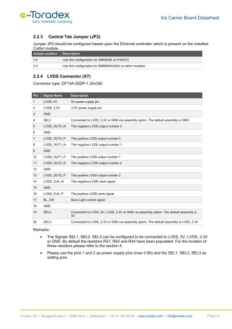
<strong>Iris</strong> Carrier Board Datasheet2.2.3 Central Tab Jumper (JP2)Jumper JP2 should be configured based upon the Ethernet controller which is present on the installedColibri module.Jumper positionDescription1-2 Use this configuration for DM9000E on PXA2702-3 Use this configuration for DM9000A/ASIX on other modules2.2.4 LVDS Connector (X7)Connector type: DF13A-20DP-1.25v(56)Pin Signal Name Description1 LVDS_5V 5V power supply pin2 LVDS_3.3V 3.3V power supply pin3 GND4 SEL1 Connected to LVDS_3.3V or GND via assembly option. The default assembly is GND5 LVDS_OUT0_N The negative LVDS output number 06 GND7 LVDS_OUT0_P The positive LVDS output number 08 LVDS_OUT1_N The negative LVDS output number 19 GND10 LVDS_OUT1_P The positive LVDS output number 111 LVDS_OUT2_N The negative LVDS output number 212 GND13 LVDS_OUT2_P The positive LVDS output number 214 LVDS_CLK_N The negative LVDS clock signal15 GND16 LVDS_CLK_P The positive LVDS clock signal17 BL_ON Back Light control signal18 GND19 SEL2 Connected to LVDS_5V, LVDS_3.3V or GND via assembly option. The default assembly is5V20 SEL3 Connected to LVDS_3.3V or GND via assembly option. The default assembly is LVDS_3.3VRemarks:• The Signals SEL1, SEL2, SEL3 can be configured to be connected to LVDS_5V, LVDS_3.3Vor GND. By default the resistors R37, R42 and R44 have been populated. For the location ofthese resistors please refer to the section 4.• Please use the pins 1 and 2 as power supply pins (max 0.9A) and the SEL1, SEL2, SEL3 assetting pins.<strong>Toradex</strong> AG l Altsagenstrasse 5 l 6048 Horw l Switzerland l +41 41 500 48 00 l www.toradex.com l info@toradex.com Page | 9


