Robin Z5xx Datasheet - Toradex
Robin Z5xx Datasheet - Toradex
Robin Z5xx Datasheet - Toradex
Create successful ePaper yourself
Turn your PDF publications into a flip-book with our unique Google optimized e-Paper software.
<strong>Robin</strong> <strong>Z5xx</strong> <strong>Datasheet</strong>5.2.2 ATX-Like Configuration using SUS_S5# as PS_ON ................................................................. 255.2.3 ATX-Like Configuration using SUS_S3# as PS_ON ................................................................. 265.2.4 Configuration without Standby Supply ...................................................................................... 275.2.5 Minimum Power Configuration .................................................................................................. 285.3. Power Sequences ............................................................................................................................. 295.3.1 G3 to S0 controlled by Power Button ........................................................................................ 295.3.2 G3 to S0 without Waiting for Power Button ............................................................................... 305.3.3 S0 to S5 Shutdown .................................................................................................................... 305.3.4 S0 to S3 Suspend to RAM......................................................................................................... 315.3.5 S3 to S0 Resume ...................................................................................................................... 315.3.6 Power Button Emergency Shutdown ......................................................................................... 32Wakeup Events ......................................................................................................................................... 326. <strong>Robin</strong> Embedded Controller ................................................................................................. 336.1. INTERRUPT OUT Report Contents (Real time data) ....................................................................... 336.1.1 GPIO Command ........................................................................................................................ 346.1.2 Watchdog................................................................................................................................... 346.1.3 I 2 C interface ............................................................................................................................... 346.2. INTERRUPT IN Report Contents (Real time data) ........................................................................... 356.2.1 Frame Number .......................................................................................................................... 356.2.2 GPIO Values .............................................................................................................................. 356.2.3 I 2 C interface ............................................................................................................................... 356.2.4 System Status ........................................................................................................................... 356.3. FEATURE Report Commands for GPIO ........................................................................................... 366.3.1 Report Mode .............................................................................................................................. 366.3.2 Sample Rate .............................................................................................................................. 366.3.3 GPIO Direction .......................................................................................................................... 366.3.4 GPIO Output Mode .................................................................................................................... 376.3.5 Standby Configuration ............................................................................................................... 376.4. FEATURE Report Commands for Watchdog .................................................................................... 376.4.1 Watchdog mode ........................................................................................................................ 376.4.2 Strobe Interval ........................................................................................................................... 386.4.3 Watchdog Enable Delay ............................................................................................................ 386.4.4 Watchdog Source ...................................................................................................................... 386.4.5 Service Watchdog ..................................................................................................................... 396.4.6 Reset Watchdog Pin .................................................................................................................. 396.5. FEATURE Report Commands for Power Management ................................................................... 396.5.1 Boot Mode ................................................................................................................................. 396.5.2 S3 Signalization Mode ............................................................................................................... 396.5.3 Reset THRM Pin ........................................................................................................................ 406.6. <strong>Toradex</strong> <strong>Z5xx</strong> Tweaker Tool ............................................................................................................. 407. Watchdog ............................................................................................................................ 418. Thermal considerations ........................................................................................................ 438.1. Temperature Range .......................................................................................................................... 438.2. Notes for a custom heatsink or heatspreader ................................................................................... 438.3. Temperature sensor chip .................................................................................................................. 448.3.1 Warning signal ........................................................................................................................... 448.3.2 Critical Temperature signal........................................................................................................ 448.3.3 Default BIOS values .................................................................................................................. 449. Technical Specification ........................................................................................................ 45<strong>Toradex</strong> AG l Altsagenstrasse 5 l 6048 Horw l Switzerland l +41 41 500 48 00 l www.toradex.com l info@toradex.com Page | 4
<strong>Robin</strong> <strong>Z5xx</strong> <strong>Datasheet</strong>9.1. Electrical Characteristics ................................................................................................................... 459.2. Power Consumption .......................................................................................................................... 459.3. Mechanical characteristics ................................................................................................................ 469.3.1 Mechanical characteristics of <strong>Robin</strong> <strong>Z5xx</strong> V1.0......................................................................... 469.3.2 Mechanical characteristics of <strong>Robin</strong> <strong>Z5xx</strong> V2.0......................................................................... 469.3.3 Details with height information .................................................................................................. 479.4. RoHS Compliance ............................................................................................................................. 47<strong>Toradex</strong> AG l Altsagenstrasse 5 l 6048 Horw l Switzerland l +41 41 500 48 00 l www.toradex.com l info@toradex.com Page | 5
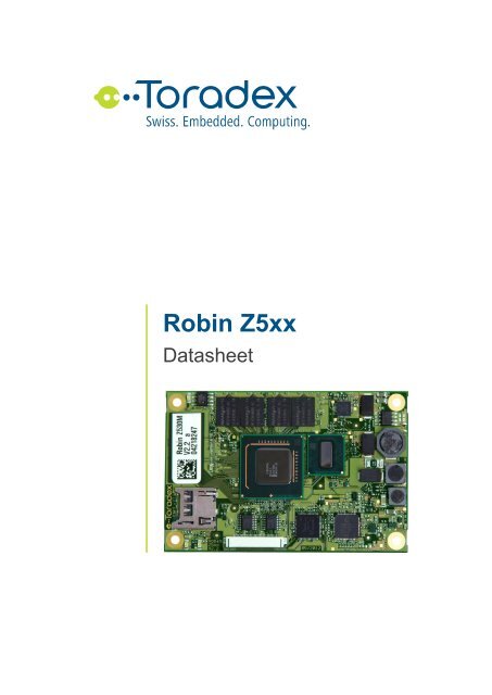
<strong>Robin</strong> <strong>Z5xx</strong> <strong>Datasheet</strong>1. Introduction<strong>Robin</strong> <strong>Z5xx</strong> is an embedded Nano COM Express computer module designed for high performancecomputing with low power consumption. <strong>Robin</strong> <strong>Z5xx</strong> is based on the Intel® Atom Z530 or Z510processors and the Intel® System Controller Hub US15W. <strong>Robin</strong> Z530 is based on the Intel® AtomZ530 processor running at 1.6GHz. <strong>Robin</strong> Z510 is a lower cost module based on the Intel® AtomZ510 processor running at 1.1GHz.<strong>Robin</strong> Z530 offers a single PCI Express x1 lane, GLAN, HDA and up to 7 High Speed USB ports forfast signal connectivity. One USB port can be configured as USB client. In standard configuration, itfeatures dual independent graphical outputs with VGA and LVDS.<strong>Robin</strong> <strong>Z5xx</strong> provides various possibilities for storing data. A Solid State Drive (SSD) and a MicroSDcard slot are provided on the module itself. A SATA and SDIO interface are available on the COMExpress connector. A 30 pin FFC connector features an additional SDIO channel for SD cards,MMC cards, WLAN adaptors, Bluetooth adaptors, modems, IrDA adapters, RFID readers or GPSmodules.1.1. Reference DocumentsFor detailed technical information about the components of the <strong>Robin</strong> module and the COM Expressstandard, please refer to the documents listed below.1.1.1 COM Express Design GuideGuidelines for designing a COM Express carrier boardhttp://www.comexpress-pnp.org/uploads/media/COMExpressPnP_DG_09.pdf1.1.2 COM Express Reference Board SchematicsSchematic diagrams of the COM Express evaluation carrier boardhttp://www.comexpress-pnp.org/uploads/media/CEVAPnPSA0_09.pdf1.1.3 Programming Guide to the Oak Sensor FamilyApplication note regarding the access of the <strong>Robin</strong> Embedded Controller (which is softwarecompatible with the <strong>Toradex</strong> Oak Sensor Family of <strong>Toradex</strong>)http://files.toradex.com/Oak/Oak_ProgrammingGuide.pdf1.1.4 Cypress CY8C24794Embedded Controllerhttp://www.cypress.com/?docID=266761.1.5 Chrontel CH7022SDVO to VGA converterhttp://www.chrontel.com/pdf/7021-7022ds.pdf<strong>Toradex</strong> AG l Altsagenstrasse 5 l 6048 Horw l Switzerland l +41 41 500 48 00 l www.toradex.com l info@toradex.com Page | 6
<strong>Robin</strong> <strong>Z5xx</strong> <strong>Datasheet</strong>2. Features2.1. Block Diagram<strong>Robin</strong> <strong>Z5xx</strong> ModuleCOM ExpressCarrier BoardDiodeCPUIntel AtomZ530/Z510VoltageRegulators4.75-14.5VPowerSupplyTemp SensLM95245FSB: 533/400 MHz 6)MicroSD SlotSMBSDIOBatteryManagement 2)2SDIOSMBHDALVDSHDACodecAudio1LVDSDDR2MemoryDownDDR2IDEIDE2SATAJMH330SATA1SATASCHUS15WIDSSD4,2,1GBFWHSST49LF008ABuzzerLPCSIO 1)COMLPTPS/2FloppyFWH 4)SocketSlot 1Slot 0533/400 6) VGAVGA DAC1VGAOptionalSMBPower Management SignalsEmbeddedControllerCY8C24794PCIeSDVOCH7022 5) 1OptionalPCIe to LANRTL8111C/Dor RTL8102ESVDOOptionalPCIePCIeGLANUSBPWR ButtonReset ButtonGPIORSTPWR1SDVO 5)1x PCIe(x1)1x PCIe(x1) 7)LAN7USB8GPIO1) Super IO is only supported by the newest BIOS versions. Please contact <strong>Toradex</strong> for moreinformation.2) Battery Management requires the customization of the BIOS/Driver. Please contact <strong>Toradex</strong>for more information.3) Assembly option for higher volumes: Realtek RTL8102E Fast Ethernet controller instead ofRealtek RTL8111C/D Gigabit Ethernet controller.4) Optional firmware hub (FWH) on base board. Onboard FWH can be disabled.5) Assembly option for higher volumes: SDVO output instead of on Module VGA DAC.6) DDR2 and FSB are 533 for <strong>Robin</strong> Z530 and 400 on Z510.7) Assembly option for higher volumes: Additional PCIe instead of Ethernet controller.<strong>Toradex</strong> AG l Altsagenstrasse 5 l 6048 Horw l Switzerland l +41 41 500 48 00 l www.toradex.com l info@toradex.com Page | 7
<strong>Robin</strong> <strong>Z5xx</strong> <strong>Datasheet</strong>2.2. VariantsFrom <strong>Toradex</strong>, several variants are available. Those variants differ in the assembled key componentsand price.Variant S M LCPU Z510 Z530 Z530FSB, DDR Frequency 400MHz 533MHz 533MHzDDR RAM 512MByte 512MByte 1GByteSolid State Disk (SSD) 1/2GByte 2GByte 4GBytePCB Version V1.0 V1.0 V2.0PCB thickness 1.6mm 1.6mm 2.0mm2.3. CPU and Chipset<strong>Robin</strong> with CPU Z530<strong>Robin</strong> with CPU Z510Processor Intel® Atom Z530 Intel® Atom Z510CPU Clock 1.6 GHz 1.1 GHzFront Side Bus 533MHz 400MHzInstruction Cache 32kByte 32kByteL1 Cache 24kByte 24kByteL2 Cache 512kByte 512kByteHyper Thread Yes NoChipset Intel® System Controller Hub US15W Intel® System Controller Hub US15WVideo Controller Integrated Intel® Graphics, Intel® GMA 500,HDTV/HD capableDecoder for MPEG2(HD) /H2.64Integrated Intel® Graphics, Intel® GMA 500,HDTV/HD capableDecoder for MPEG2(HD) /H2.64<strong>Toradex</strong> AG l Altsagenstrasse 5 l 6048 Horw l Switzerland l +41 41 500 48 00 l www.toradex.com l info@toradex.com Page | 8
<strong>Robin</strong> <strong>Z5xx</strong> <strong>Datasheet</strong>2.4. Interfaces<strong>Robin</strong> <strong>Z5xx</strong> V1.0 / V2.0PCI ExpressExpressCard1 PCIe x11 SupportedEthernet 10/100/1000 Mbit LAN 1)AudioSerial ATAUSBSD Memory CardSDIOLVDSIntel® High Definition Audio (24bit/96kHz)1 (IDE bridge)7x USB 2.0 (1 channel configurable as client)MicroSD slot on board1 on Com Express connector (4bit)1 on separate FFC connector (8bit)Single Channel 18/24 bit WXGA 1366x768SDVO No 2)Analog VGATV outLPCSMBI 2 CGPIOYesYesYesYesYes (over Embedded Controller)8 over Embedded Controller, available on-<strong>Robin</strong> V1.0 FFC-<strong>Robin</strong> V2.0 FFC or Com Express connectorNotes:1) Assembly option for higher volumes: Realtek RTL8102E Fast Ethernet controller instead ofRealtek RTL8111C Gigabit Ethernet controller.2) Assembly option for higher volumes: SDVO output instead of Chrontel CH7022.<strong>Toradex</strong> AG l Altsagenstrasse 5 l 6048 Horw l Switzerland l +41 41 500 48 00 l www.toradex.com l info@toradex.com Page | 9
<strong>Robin</strong> <strong>Z5xx</strong> <strong>Datasheet</strong>2.5. Differences between <strong>Robin</strong> V2.0 to <strong>Robin</strong> V1.0By <strong>Robin</strong> V1.0 and V2.0 the PCB version is meant.2.5.1 DDR2 x8 instead of x16 DDR2<strong>Robin</strong> V2.0 utilizes DDR2 RAM devices with a x8 bit bus width in contrast to <strong>Robin</strong> V1.0, which utilizesDDR2 RAM devices with x16 bit bus width. This allows <strong>Robin</strong> V2.0 to provide up to 2GByte of RAM, incomparison with the maximum 1GByte of RAM available on <strong>Robin</strong> V1.0.2.5.2 SDIO / GPIO switch<strong>Robin</strong> V2.0 provides either a GPIO or SDIO interface on the COM Express connector. The sameGPIO signals available on the FFC connector of <strong>Robin</strong> V1.0 are also available on <strong>Robin</strong> V2.0.2.5.3 PCB thicknessThe <strong>Robin</strong> V2.0 PCB has a nominal thickness of 2mm compared to 1.6mm for <strong>Robin</strong> V1.0.This may have an impact for customers who have implemented a mechanical design that is affectedby PCB thickness. To ensure compatibility between <strong>Robin</strong> V1.0 and V2.0 in such designs, <strong>Toradex</strong> willprovide a dedicated Heatspreader for <strong>Robin</strong> V2.0, which will compensate for the PCB heightdifference.2.5.4 FFC shiftedThe FFC connector has been shifted closer to the PCB edge with respect to the front edge of theconnector. Its position with respect to the adjacent PCB edge has not changed.2.5.5 Thermal sensorThe thermal sensor has been moved away from the key heat sources (the Atom processor andUS15W system control hub) to provide a more accurate measurement of the module temperature. TheAtom processor temperature is still measured internally to the core.<strong>Toradex</strong> AG l Altsagenstrasse 5 l 6048 Horw l Switzerland l +41 41 500 48 00 l www.toradex.com l info@toradex.com Page | 10
<strong>Robin</strong> <strong>Z5xx</strong> <strong>Datasheet</strong>3. <strong>Robin</strong> Connectors3.1. Physical LocationThe <strong>Robin</strong> Z530 and Z510 computer modules comply with the COM Express pin out type 1 for mostof the signals. Only one 220 pin COM Express connector is available. A 30 pin FFC connectorfeaturing an additional SDIO channel and 8 GPIOs is available. An on board MicroSD slot is alsoavailable.TopBottomMicroSD30 Pin FFCCom Express TM3.2. Signal Notation3.2.1 Signal TypesTypeIOIOODODIODONCREFNote:Input to the moduleOutput from the moduleBi-directional input/output signalOpen drain bi-directionalOpen drain inputOpen drain outputNot ConnectedReference SignalA “#” symbol after a signal name refers to an active low signal, indicating a signal is in theactive state when driven to a low level.<strong>Toradex</strong> AG l Altsagenstrasse 5 l 6048 Horw l Switzerland l +41 41 500 48 00 l www.toradex.com l info@toradex.com Page | 11
<strong>Robin</strong> <strong>Z5xx</strong> <strong>Datasheet</strong>3.2.2 Signal Voltage RailRail5 5V3.3 3.3V3.3/5 Nominal 3.3V; 5V tolerant input2.5 2.5VAPWRLVDSPCIeSATAAnalogPower supply and groundLow voltage differential signalingPCI Express differential signalingSerial ATA differential signaling3.3. COM Express Connector Pin AssignmentThe following pin assignment is the same for both <strong>Robin</strong> Z530 and Z510. Optional pin assignmentsare marked by a 1) whereas differences to the COM Express pin out type 1 are marked by a 2) .Pin Signal Type Rail DescriptionA1 GND PWR GroundA2 GBE0_MDI3- IO A Gigabit LAN pair 3 (negative); not used for fast EthernetA3 GBE0_MDI3+ IO A Gigabit LAN pair 3 (positive); not used for fast EthernetA4 GBE0_LINK100# O 3.3 LED LAN speed 100MbpsA5 GBE0_LINK1000# O 3.3 LED LAN speed 1GbpsA6 GBE0_MDI2- IO A Gigabit LAN pair 2 (negative); not used for fast EthernetA7 GBE0_MDI2+ IO A Gigabit LAN pair 2 (positive); not used for fast EthernetA8 GBE0_LINK# O 3.3 LED LAN link indicatorA9 GBE0_MDI1- IO A Gigabit LAN pair 1 (negative); fast Ethernet RX-A10 GBE0_MDI1+ IO A Gigabit LAN pair 1 (positive); fast Ethernet RX+A11 GND PWR GroundA12 GBE0_MDI0- IO A Gigabit LAN pair 0 (negative); fast Ethernet TX-A13 GBE0_MDI0+ IO A Gigabit LAN pair 0 (positive); fast Ethernet TX+A14 GBE0_CTREF REF A Reference voltage for the magnetic center tap.<strong>Robin</strong>: not connected.A15 SUS_S3# O 3.3 Indicates the system is suspended to RAMA16 SATA0_TX+ O SATA Serial ATA transmit channel 0 (positive)A17 SATA0_TX- O SATA Serial ATA transmit channel 0 (negative)A18 SUS_S4# O 3.3 Indicates the system is suspended to disk.Note: <strong>Robin</strong> does not distinguish suspend state S4 and S5A19 SATA0_RX+ I SATA Serial ATA receive channel 0 (positive)A20 SATA0_RX- I SATA Serial ATA receive channel 0 (negative)A21 GND PWR GroundA22-A23 NC NC Not ConnectedA24 SUS_S5# Indicates the system is in SoftOff state. Can be used to control anATX power supply.Note: <strong>Robin</strong> does not distinguish suspend states S4 and S5<strong>Toradex</strong> AG l Altsagenstrasse 5 l 6048 Horw l Switzerland l +41 41 500 48 00 l www.toradex.com l info@toradex.com Page | 12
<strong>Robin</strong> <strong>Z5xx</strong> <strong>Datasheet</strong>Pin Signal Type Rail DescriptionA25-A26 NC NC Not ConnectedA27 BATLOW# ODI 3.3 Indicates that the external battery is low,47kΩ pull-up on moduleA28 ATA_ACT# O 3.3 LED indicator for the activity of SATAA29 AC_SYNC O 3.3 48kHz audio codec synchronization signalA30 AC_RST# O 3.3 Reset output for audio codecA31 GND PWR GroundA32 AC_BITCLK IO 3.3 12.228MHz audio codec serial clockA33 AC_SDOUT O 3.3 Serial data output to the audio codecA34 BIOS_DISABLE# ODI 3.3 Module BIOS disable. Pull low to disable BIOS on module,10kΩ pull-up on moduleA35 THRMTRIP# O 3.3 Indicates the entering of the CPU in thermal shutdownA36 USB6- IO 3.3 USB channel 6 (negative) 4)A37 USB6+ IO 3.3 USB channel 6 (positive) 4)A38 USB_6_7_OC# ODI 3.3 USB Over current channels 6 and 7,10kΩ pull-up on moduleA39 USB4- IO 3.3 USB channel 4 (negative) 4)A40 USB4+ IO 3.3 USB channel 4 (positive) 4)A41 GND PWR GroundA42 USB2- IO 3.3 USB channel 2 (negative) 4)A43 USB2+ IO 3.3 USB channel 2 (positive) 4)A44 USB_2_3_OC# ODI 3.3 USB Over current channels 2 and 3,10kΩ pull-up on moduleA45 USB0- IO 3.3 USB channel 0 (negative) 4)A46 USB0+ IO 3.3 USB channel 0 (positive) 4)A47 VCC_RTC I PWR RTC battery input, nominal 3.0VA48 EXCD0_PERST# O 3.3 ExpressCard card 0 reset signalA49 EXCD0_CPPE# I 3.3 ExpressCard card 0 request signalA50 LPC_SERIRQ IO 3.3 LPC serial interruptA51 GND PWR GroundA52 SDVO_CLK+ O PCIe Serial digital video clock output (positive) 1)A53 SDVO_CLK- O PCIe Serial digital video clock output (negative) 1)A54 SDIO0_DATA0 IO 3.3 SDIO Data 0 5)A55 SDVO_BLUE+ O PCIe Serial digital video blue output (positive) 1)A56 SDVO_ BLUE - O PCIe Serial digital video blue output (negative) 1)A57 GND PWR GroundA58 SDVO_GREEN+ O PCIe Serial digital video green output (positive) 1)A59 SDVO_ GREEN- O PCIe Serial digital video green output (negative) 1)A60 GND PWR GroundA61 SDVO_RED+ O PCIe Serial digital video red output (positive) 1)A62 SDVO_ RED- O PCIe Serial digital video red output (negative) 1)A63 SDIO0_DATA1 IO 3.3 SDIO Data 1 5)A64 PCIE_TX1+ O PCIe PCI Express transmit pair 1 (positive) 2)A65 PCIE_TX1- O PCIe PCI Express transmit pair 1 (negative) 2)A66 GND PWR Ground<strong>Toradex</strong> AG l Altsagenstrasse 5 l 6048 Horw l Switzerland l +41 41 500 48 00 l www.toradex.com l info@toradex.com Page | 13
<strong>Robin</strong> <strong>Z5xx</strong> <strong>Datasheet</strong>Pin Signal Type Rail DescriptionA67 SDIO0_DATA2 IO 3.3 SDIO Data 2 5)A68 PCIE_TX0+ O PCIe PCI Express transmit pair 0 (positive)A69 PCIE_TX0- O PCIe PCI Express transmit pair 0 (negative)A70 GND PWR GroundA71 LVDS_A0+ O LVDS LVDS channel A signal pair 0 (positive)A72 LVDS_A0- O LVDS LVDS channel A signal pair 0 (negative)A73 LVDS_A1+ O LVDS LVDS channel A signal pair 1 (positive)A74 LVDS_A1- O LVDS LVDS channel A signal pair 1 (negative)A75 LVDS_A2+ O LVDS LVDS channel A signal pair 2 (positive)A76 LVDS_A2- O LVDS LVDS channel A signal pair 2 (negative)A77 LVDS_VDD_EN O 3.3 LVDS panel power enableA78 LVDS_A3+ O LVDS LVDS channel A signal pair 3 (positive)A79 LVDS_A3- O LVDS LVDS channel A signal pair 3 (negative)A80 GND PWR GroundA81 LVDS_A_CK+ O LVDS LVDS channel A clock (positive)A82 LVDS_A_CK- O LVDS LVDS channel A clock (negative)A83 LVDS_I2C_CK ODO 3.3 LVDS I 2 C Clock (DDC)A84 LVDS_I2C_DAT OD 3.3 LVDS I 2 C Data (DDC)A85 SDIO0_DATA3 IO 3.3 SDIO Data 3 5)A86 KBD_RST# ODI 3.3 Reset input from optional keyboard controller,47kΩ pull-up on moduleA87 KBD_A20GATE ODI 3.3 A20 gate input from optional keyboard controller,10kΩ pull-up on moduleA88 PCIE0_CK_REF+ O PCIe PCI Express clock reference output for all PCIe lanes (positive)A89 PCIE0_CK_REF- O PCIe PCI Express clock reference output for all PCIe lanes (negative)A90 GND PWR GroundA91-A92 NC NC Not ConnectedA93 SDIO0_CLK O 3.3 SDIO Clock output 5)A94-A95 NC NC Not ConnectedA96 GND PWR GroundA97-A99 VCC_Main PWR Main power inputA100 GND PWR GroundA101-A109VCC_Main I PWR Main power inputA110 GND PWR GroundB1 GND PWR GroundB2 GBE0_ACT# O 3.3 LAN activation indicator LEDB3 LPC_FRAME# O 3.3 Indicates the start of an LPC cycleB4 LPC_AD0 IO 3.3 LPC multiplexed address, command and data bus 0B5 LPC_AD1 IO 3.3 LPC multiplexed address, command and data bus 1B6 LPC_AD2 IO 3.3 LPC multiplexed address, command and data bus 2B7 LPC_AD3 IO 3.3 LPC multiplexed address, command and data bus 3B8-B9 NC NC Not ConnectedB10 LPC_CLK O 3.3 LPC clock output, 33MHz, usage of a clock repeater in case ofexternal BIOS not allowed<strong>Toradex</strong> AG l Altsagenstrasse 5 l 6048 Horw l Switzerland l +41 41 500 48 00 l www.toradex.com l info@toradex.com Page | 14
<strong>Robin</strong> <strong>Z5xx</strong> <strong>Datasheet</strong>Pin Signal Type Rail DescriptionB11 GND PWR GroundB12 PWRBTN# ODI 3.3 Power button input (active on falling edge),47kΩ pull-up on moduleB13 SMB_CK OD 3.3 SMBus clockB14 SMB_DAT OD 3.3 SMBus dataB15 SMB_ALERT# ODI 3.3 SMBus Alert, can be used to generate an SMI# or to wake thesystem,10kΩ pull-up on moduleB16-B17 NC NC Not ConnectedB18 SUS_STAT# O 3.3 Indicates imminent suspend operation, used to notify LPC devicesB19-B20 NC NC Not ConnectedB21 GND PWR GroundB22-B23 NC NC Not ConnectedB24 PWR_OK I 3.3 Power OK from main power supplyB25-B26 NC NC Not ConnectedB27 WDT O 3.3 Indicates that a watchdog time-out event has occurred. The pinremains high until the software clears the bit.B28 AC_SDIN2 I 3.3 Serial data input 1 from the audio codec 3)B29 AC_SDIN1 I 3.3 Serial data input 1 from the audio codecB30 AC_SDIN0 I 3.3 Serial data input 0 from the audio codecB31 GND PWR GroundB32 SPKR O 3.3 Speaker outputB33 I2C_CK OD 3.3 General purpose I 2 C clock, on the module provided by ECB34 I2C_DAT OD 3.3 General purpose I 2 C data, on the module provided by ECB35 THRM# ODI 3.3 Over temperature indication input from off-module temperaturesensor,47kΩ pull-up on moduleB36 USB7- IO 3.3 USB channel 7 (negative); configurable as USB client 4)B37 USB7+ IO 3.3 USB channel 7 (positive); configurable as USB client 4)B38 USB_4_5_OC# ODI 3.3 USB Over current channels 4 and 5,10kΩ pull-up on moduleB39-B40 NC NC Not ConnectedB41 GND PWR GroundB42 USB3- IO 3.3 USB channel 3 (negative) 4)B43 USB3+ IO 3.3 USB channel 3 (positive) 4)B44 USB_0_1_OC# ODI 3.3 USB Over current channels 0 and 1,10kΩ pull-up on moduleB45 USB1- IO 3.3 USB channel 1 (negative) 4)B46 USB1+ IO 3.3 USB channel 1 (positive) 4)B47-B48 NC NC Not ConnectedB49 SYS_RESET# ODI 3.3 Reset button input (active low),47kΩ pull-up on moduleB50 CB_RESET# O 3.3 Reset output of the module for the carrier boardB51 GND PWR GroundB52-B53 NC NC Not ConnectedB54 SDIO0_CMD O 3.3 SDIO command output 5)B55 SDVO_STALL+ I PCIe Serial digital video stall input (positive) 1)<strong>Toradex</strong> AG l Altsagenstrasse 5 l 6048 Horw l Switzerland l +41 41 500 48 00 l www.toradex.com l info@toradex.com Page | 15
<strong>Robin</strong> <strong>Z5xx</strong> <strong>Datasheet</strong>Pin Signal Type Rail DescriptionB56 SDVO_ STALL - I PCIe Serial digital video stall input (negative) 1)B57 SDIO0_WP I 3.3 SDIO write protect input 5)B58 SDVO_INT+ I PCIe Serial digital video interrupt input (positive) 1)B59 SDVO_ INT - I PCIe Serial digital video interrupt input (negative) 1)B60 GND PWR GroundB61 SDVO_TVCLKIN+ I PCIe Serial digital video TV clock input (positive) 1)B62 SDVO_ TVCLKIN - I PCIe Serial digital video TV clock input (negative) 1)B63 SDIO0_CD# I 3.3 SDIO card detect input 5)B64 PCIE_RX1+ I PCIe PCI Express receive pair 1 (positive) 2)B65 PCIE_RX1- I PCIe PCI Express receive pair 1 (negative) 2)B66 WAKE0# ODI 3.3 PCI Express wake up input,1kΩ pull-up on moduleB67 WAKE1# ODI 3.3 General purpose wake up input,47kΩ pull-up on moduleB68 PCIE_RX0+ I PCIe PCI Express receive pair 0 (positive)B69 PCIE_RX0- I PCIe PCI Express receive pair 0 (negative)B70 GND PWR GroundB71-B78 NC NC Not ConnectedB79 LVDS_BKLT_EN O 3.3 Backlight enable for LVDS displayB80 GND PWR GroundB81-B82 NC NC Not ConnectedB83 LVDS_BKLT_CTRL O 3.3 Backlight brightness control for LVDS displayB84-B87 VCC_5V_SBY I PWR Optional standby power input, 5V nominalB88 NC NC Not ConnectedB89 VGA_RED O A VGA red outputB90 GND PWR GroundB91 VGA_GRN O A VGA green outputB92 VGA_BLU O A VGA blue outputB93 VGA_HSYNC O 5 VGA horizontal sync outputB94 VGA_VSYNC O 5 VGA vertical sync outputB95 VGA_I2C_CK ODO 3.3 VGA DDC clock outputB96 VGA_I2C_DAT OD 3.3 VGA DDC data signalB97 TV_DAC_A O 3.3 TV DAC channel AB98 TV_DAC_B O 3.3 TV DAC channel BB99 TV_DAC_C O 3.3 TV DAC channel CB100 GND PWR GroundB101-B109VCC_Main I PWR Main power inputB110 GND PWR Ground1) Assembly option for higher volumes: SDVO instead of VGA /TV.2) Assembly option for higher volumes: Additional PCIe instead of GLAN3) Assembly option for higher volumes: B28 to B29 on module shorted4) Refer to chapter 4.3.1 USB mapping5) Refer to chapter 3.3.1 SDIO / GPIO signals<strong>Toradex</strong> AG l Altsagenstrasse 5 l 6048 Horw l Switzerland l +41 41 500 48 00 l www.toradex.com l info@toradex.com Page | 16
<strong>Robin</strong> <strong>Z5xx</strong> <strong>Datasheet</strong>3.3.1 SDIO / GPIO signalsOn <strong>Robin</strong> <strong>Z5xx</strong> V2.0, either the SDIO or GPIO signals can be switched to the COM Express connectorthrough a configuration setting in the BIOS. This feature is not available on <strong>Robin</strong> V1.0, where theSDIO interface is permanently connected to the COM Express Connector. The BIOS setting isavailable for <strong>Robin</strong> V1.0 BIOS, but is not changeable.COM Express Pin BIOS setting to “SDIO”, <strong>Robin</strong> V1.0 and V2.0 BIOS setting to “GPIO”, <strong>Robin</strong> V2.0A54 SLOT0_DATA0 USB_GPIO0A63 SLOT0_DATA1 USB_GPIO1A67 SLOT0_DATA2 USB_GPIO2A85 SLOT0_DATA3 USB_GPIO3A93 SLOT0_CLK USB_GPIO4B54 SLOT0_CMD USB_GPIO5B57 SLOT0_WP USB_GPIO6B63 SLOT0_CD# USB_GPIO7Note: The same GPIO signals are always available on the FFC for both PCB versions 1.0 and 2.0.<strong>Toradex</strong> AG l Altsagenstrasse 5 l 6048 Horw l Switzerland l +41 41 500 48 00 l www.toradex.com l info@toradex.com Page | 17
<strong>Robin</strong> <strong>Z5xx</strong> <strong>Datasheet</strong>3.4. Assignment of additional FFC ConnectorConnector: FFC 30 pins, 0.5 mm pitch, bottom contact (example MOLEX 52437-3072)Pin Signal Type Rail Description1 SDIO2_CLK O 3.3 SDIO channel 2 clock,24 MHz for SD and SDIO, 48 MHz for MMC2 GND PWR Ground3 SDIO2_CMD OD/IO3.3 SDIO channel 2 command,used for card initialization and transfer of commands,39kΩ pull-up on module4 SDIO2_LED O 3.3 SDIO channel 2 LED output,can be used to drive an external LED over a transistor to indicate transfer onthe bus5 SDIO2_CD# ODI 3.3 SDIO channel 2 card detect,the present of the card is signalized by pulling the signal to ground, 10kΩ pullupon module6 SDIO2_WP ODI 3.3 SDIO channel 2 write protect,denote the state of the write-protect tab on SD card, pull signal to ground toenable writing, 10kΩ pull-up on module7 SDIO2_PWR# O 3.3 SDIO channel 2 power enable,can be used to enable the power being supplied to an SDIO/MMC device8 VCC_3.3S_OUT O PWR 3.3V power output for powering a SDIO device.The power rail is only available in S0 state.9 SDIO2_DATA0 IO 3.3 SDIO channel 2 data line (channel 2 is 8 bit capable)10 SDIO2_DATA1 IO 3.3 SDIO channel 2 data line (channel 2 is 8 bit capable)11 GND PWR Ground12 SDIO2_DATA2 IO 3.3 SDIO channel 2 data line (channel 2 is 8 bit capable)13 SDIO2_DATA3 IO 3.3 SDIO channel 2 data line (channel 2 is 8 bit capable)14 SDIO2_DATA4 IO 3.3 SDIO channel 2 data line (channel 2 is 8 bit capable)15 SDIO2_DATA5 IO 3.3 SDIO channel 2 data line (channel 2 is 8 bit capable)16 GND PWR Ground17 SDIO2_DATA6 IO 3.3 SDIO channel 2 data line (channel 2 is 8 bit capable)18 SDIO2_DATA7 IO 3.3 SDIO channel 2 data line (channel 2 is 8 bit capable)19 VCC_3.3S_OUT O PWR 3.3V power output for powering a SDIO device.The power rail is only available in S0 state.20 USB_CLIENT_DETI 3.3 USB client connect detection, indicates connection to an external USB hosthas been established, needs voltage level shifter21 SDIO0_LED O 3.3 SDIO channel 0 LED output,can be used to drive an external LED over a transistor to indicate transfer onthe bus22 GPIO_0 IO 3.3 General Purpose input/output23 GPIO_1 IO 3.3 General Purpose input/output24 GND PWR Ground25 GPIO_2 IO 3.3 General Purpose input/output26 GPIO_3 IO 3.3 General Purpose input/output27 GPIO_4 IO 3.3 General Purpose input/output28 GPIO_5 IO 3.3 General Purpose input/output29 GPIO_6 IO 3.3 General Purpose input/output30 GPIO_7 IO 3.3 General Purpose input/output<strong>Toradex</strong> AG l Altsagenstrasse 5 l 6048 Horw l Switzerland l +41 41 500 48 00 l www.toradex.com l info@toradex.com Page | 18
<strong>Robin</strong> <strong>Z5xx</strong> <strong>Datasheet</strong>4. Signal Description4.1. System Memory<strong>Robin</strong> <strong>Z5xx</strong> modules incorporate fast DDR2 on-board system memory with the followingcharacteristics:Attribute <strong>Robin</strong> <strong>Z5xx</strong> V1.0 <strong>Robin</strong> <strong>Z5xx</strong> V2.0Size 512MByte 512MByte / 1GByte / 2GByteMemory organization X16 bits X8 bitsMemory speed 533MT/s for Z530 (400MT/s for Z510) 533MT/s for Z530 (400MT/s for Z510)4.2. Serial ATAThe Serial ATA (SATA) interface is provided through the JMH330 IDE to SATA Bridge from JMicron.No additional driver is required for the SATA interface.4.3. USB InterfaceThe US15W (System Controller Hub on the <strong>Robin</strong> module) features Enhanced Host ControllerInterface (EHCI) with 8 USB ports. All 8 ports support USB high speed (480Mbit/s). However, it shouldbe noted that only 6 of these ports support low speed (1.5Mbit/s) and full speed (12Mbit/s).7 USB ports are available through the COM Express connector. Port 5 of the US15W is used forcommunication with the <strong>Robin</strong> Embedded Controller and is therefore not available on the moduleconnector..4.3.1 USB mappingThe following table shows how the US15W USB signals are mapped to the COM Express USBchannels.COM ExpressConnector USB channelUS15W USB Port0 01 12 33 44 6 (480MBit only)5 Not available6 7 (480MBit only)7 (client) 2 (client)<strong>Toradex</strong> AG l Altsagenstrasse 5 l 6048 Horw l Switzerland l +41 41 500 48 00 l www.toradex.com l info@toradex.com Page | 19
<strong>Robin</strong> <strong>Z5xx</strong> <strong>Datasheet</strong>4.3.2 USB clientUSB port 7 on the connector can be configured as a client. The presence of a host device connectedto the client port is detected by monitoring the USB bus voltage. The detection mechanism can beimplemented using a level-shifting circuit (as shown below) connected to the USB_CLIENT_DETsignal (pin 20 of the FFC connector on the <strong>Robin</strong> module).+3 . 3 V100k4. 7kUSB_CLI ENT_DETVCCD-D+IDGND12345GND+5 V_USB_CLI ENTUSB_2_DATA-USB_2_DATA+GND100kGNDGND4. 7uFGND4.4. Ethernet ControllerThe <strong>Robin</strong> <strong>Z5xx</strong> module features an onboard RTL8111C/D gigabit Ethernet controller from Realtekwhich supports a 10/100/1000 Base-T interface. This controller is directly connected to the PCIExpress interface of the US15W. The device auto-negotiates the use of the different speeds andincludes features such as crossover detection with auto-correction, polarity correction and cross-talkcancellation.For high volumes, the <strong>Robin</strong> module can be assembled with the RTL8102E Ethernet controller insteadof the RTL8111C/D. This offers a suitable solution for very price sensitive, high volume projectsrequiring only a 10/100 Base-T fast Ethernet controller (please contact <strong>Toradex</strong> for furtherinformation).4.5. PCI ExpressThe US15W chipset features two x1 PCI Express lanes. PCIe lane 0 of the US15W is directlyavailable at the COM Express connector. PCIe lane 1is connected directly to the Ethernet controllerand is not available for general use.4.6. ExpressCardThe <strong>Robin</strong> <strong>Z5xx</strong> module supports the two additional signals required for the ExpressCard interface(card detect and card reset). The ExpressCard interface makes use of both a USB port and a singlePCI Express lane (although an attached ExpressCard device may only make use of one of theseinterfaces).4.7. SDIO, SD Card and MMCThe Intel® US15W features 3 SDIO buses. Each SDIO bus can be used for SD cards,MultiMediaCards (MMC), as an SDIO interface or CE-ATA interface. The SD card and the SDIOinterface can run in either 1 bit or 4 bit mode, whereas MMC supports an additional 8 bit transfermode. Only SDIO slot 2 of the US15W is 8 bit capable; the other two are only 4bit capable.SDIO slot 1 is available on the <strong>Robin</strong> module as MicroSD card holder. Slot 0 is on the COM Expressconnector (see chapter 3.3.1) and slot 2 is available on the 30 pin FFC connector. This connector alsoprovides 3.3V power supply for SD or MMC cards. Please note that as the maximum power rating of<strong>Toradex</strong> AG l Altsagenstrasse 5 l 6048 Horw l Switzerland l +41 41 500 48 00 l www.toradex.com l info@toradex.com Page | 20
<strong>Robin</strong> <strong>Z5xx</strong> <strong>Datasheet</strong>the 3.3V supply on this connector is limited, an additional power supply may be required if theconnected SDIO device has a power requirement which exceeds this rating.4.8. VGAThe <strong>Robin</strong> module features a Chrontel SDVO to VGA and TV out converter CH7022. Please refer tothe datasheet for more information.For application specific/custom carrier board designs, remember to include the 150R load resistorsrequired at each of the VGA color outputs.For high volumes, it is an assembly option not to fit the CH7022. The SDVO signals would then berouted to the COM Express connector. Please contact <strong>Toradex</strong> for further information regardingassembly options.4.9. TV outThe <strong>Robin</strong> module features a Chrontel SDVO to VGA and TV out converter CH7022. Please refer tothe datasheet for more information.For application specific/custom carrier board designs, remember to include the 150R load resistorsrequired at each of the TV outputs.For high volumes, it is an assembly option not to fit the CH7022. The SDVO signals would then berouted to the COM Express connector. Please contact <strong>Toradex</strong> for further information regardingassembly options.The TV out signals can be configured as follows:COM Express signal Composite video Component video S-VideoTV_DAC_A CVBS Chrominance (Pb) Not usedTV_DAC_B Not used Luminance (Y) Luminance analog signal (Y)TV_DAC_C Not used Chrominance (Pr) Chrominance analog signal (C)4.10. <strong>Robin</strong> <strong>Z5xx</strong> Module LEDsLED3Top ViewLED1LED2Note: <strong>Robin</strong> <strong>Z5xx</strong> V1.0 shown; placement of the LEDs is the same for <strong>Robin</strong> V2.0.LED1: Activity indication of the on board MicroSD slot (SDIO channel 0)LED2: Activity indication of the SDIO channel 1 (available on COM express connector)<strong>Toradex</strong> AG l Altsagenstrasse 5 l 6048 Horw l Switzerland l +41 41 500 48 00 l www.toradex.com l info@toradex.com Page | 21
<strong>Robin</strong> <strong>Z5xx</strong> <strong>Datasheet</strong>LED3: On board flash drive and SATA bridge activity indication. The LED shows the activity parallel tothe ATA_ACT# signal (pin A28 on COM express connector).4.11. LPCThe LPC interface is a Low Pin Count PCI bus. Components on the carrier board such as Super IO oran external BIOS are connected to this bus.Note for external LPC devices: Don’t use a clock repeater on the carrier board for the clock signal ofthe LPC.<strong>Toradex</strong> AG l Altsagenstrasse 5 l 6048 Horw l Switzerland l +41 41 500 48 00 l www.toradex.com l info@toradex.com Page | 22
<strong>Robin</strong> <strong>Z5xx</strong> <strong>Datasheet</strong>5. Power Supply5.1. Power StatesState Common Names BehaviorG3 Mechanical Off All power supplies except the RTC battery are removed. The power consumption of thesystem is almost zero; only the RTC circuit consumes a small amount of powerS5 Soft Off Only the embedded controller on the module is powered. The embedded controller waits forthe power button to be pushed before starting the system. The power consumption in thisstate is very low.S4S3Suspend to DiskHibernationSuspend to RAMStand by, SleepThe contents of RAM are written to a non-volatile storage medium (e.g. hard disc). This allowsrecovery of the system to the state prior to entering suspend or hibernate. From the hardwareperspective, this state is equal to S5. The system is off except for the embedded controllerbeing powered. The embedded controller waits for the power button to be pushed beforestarting the system. The power consumption in this state is very low. The <strong>Robin</strong> hardwaredoes not distinguish between S4 and S5.The RAM subsystem is powered for a fast recovery of the system. Power supplies that are notrequired are switched off. Wake on LAN is supported in this state (hence the networksubsystem is powered). The <strong>Robin</strong> module requires the main power supply to generate thestandby power supply.S0 On The system is working. All power supplies are switched on. The power consumption dependson the CPU and peripheral load.The COM Express Connector features three signals for signaling the different power states to thecarrier board. As the <strong>Robin</strong> module hardware does not distinguish between power states S4 and S5,SUS_S4# and SUS_S5# are essentially the same signal.State SUS_S5# SUS_S4# SUS_S3#G3 NA NA NAS5 Low Low LowS4 Low Low LowS3 High High LowS0 High High High<strong>Toradex</strong> AG l Altsagenstrasse 5 l 6048 Horw l Switzerland l +41 41 500 48 00 l www.toradex.com l info@toradex.com Page | 23
<strong>Robin</strong> <strong>Z5xx</strong> <strong>Datasheet</strong>5.2. Power SupplyThe <strong>Robin</strong> modules are designed to run from a single power supply with a wide nominal input voltagerange of +5V to +12V. Two power supplies are optional: a +5V standby power supply and a +3Vbattery power supply (used to power the real-time clock on the module).If the standby power supply is not provided by the carrier board, the <strong>Robin</strong> module will generate therequired standby power from the main power supply using a linear voltage regulator. Hence, the <strong>Robin</strong>module supports both the S4 and S5 power states even if the standby power supply is absent, as longas the main power supply is present.The RTC power supply is powered in parallel by both the standby power supply and the 3V batterypower supply. This ensures that the real-time clock is running as long as either one of these powersupplies is present. Important: a diode must be placed between RTC Battery and the RTC Voltage pinof the module connector.5.2.1 AC Power AdaptorDepending upon the specific hardware configuration, it is likely that the power supply to the carrierboard will be forwarded directly to the <strong>Robin</strong> module (this is true for Lily V1.0, V1.1, V2.0, V2.1 andDaisy V1.0, V1.1). If an AC power adaptor is being used, please ensure that its output voltage is neverbeyond the limits of the module and carrier board. Simple AC power adaptors may have significantlyhigher output voltages than their nominal voltage in no-load operation; usage of such power adaptorscan damage both the <strong>Robin</strong> <strong>Z5xx</strong> module and carrier board.<strong>Toradex</strong> AG l Altsagenstrasse 5 l 6048 Horw l Switzerland l +41 41 500 48 00 l www.toradex.com l info@toradex.com Page | 24
<strong>Robin</strong> <strong>Z5xx</strong> <strong>Datasheet</strong>5.2.3 ATX-Like Configuration using SUS_S3# as PS_ONCOM Express Carrier Board<strong>Robin</strong> Module <strong>Z5xx</strong>12V SourceVCC_12VVoltageRegulatorsCPU/Chipset/Peripheralse.g. ATX:PS_ONCarrier BoardPeripheralsVoltage Reg.PWR_OKLDORPWR_OKSUS_S3#SUS_S5#EmbeddedController5V StbySourceVCC_5V_SBYAutom.SwitchVoltageRegulatorsRTC BatteryVCC_RTCRTC SystemIt is also possible to use the signal SUS_S3# for controlling the main power supply, which is themechanism employed by some commercially available COM Express carrier boards. To support thispower control method, the <strong>Robin</strong> module requires a change to a setting in the embedded controllerwhich enables S3 Signaling Mode. When operating in S3 Signaling Mode, the module de-asserts bothSUS_S3# and SUS_S5# simultaneously. Section 6.5.2 describes this in more detail. S3 SignalingMode can be configured using the <strong>Toradex</strong> <strong>Z5xx</strong> Tweaker tool.For new designs, <strong>Toradex</strong> does not recommend using this power control method and hence hardwareconfiguration, as it is not possible for the carrier board to differentiate between power states S5 andS3.With this power control method, the carrier board must manage the following power sequence:1. The <strong>Robin</strong> module de-asserts signals SUS_S5#, SUS_S4#and, if S3 Signaling Mode isenabled, SUS_S3#.2. The carrier board must switch on the main power supply and the necessary power supplies forany carrier board peripherals.3. If all required power supplies on the carrier board are stable, the carrier board must assert thePWR_OK signal within 10 seconds of the de-assertion of signal SUS_S5#. In the event thatthis fails to happen, the <strong>Robin</strong> module will de-assert signal SUS_S3# if it has not already doneso in step 1 (this allows the <strong>Robin</strong> module to successfully power on in order to enable S3Signaling Mode). If a further 5 seconds elapses without the PWR_OK signal asserted, the<strong>Robin</strong> module returns to power state S5 (power fail). The embedded controller can beconfigured to retry the power up sequence after 1 minute (see section 6.5.1).4. The module ramps up all the necessary power supplies to enter power state S3.5. The <strong>Robin</strong> module continues its power up process by ramping up the remaining on-boardpower supplies, releasing the reset signal and booting.Note that it is very important to enable S3 Signaling Mode when using this power control method,otherwise the shut-down and suspend power modes will not function correctly, and an additional 10seconds will be added to the power on time.<strong>Toradex</strong> AG l Altsagenstrasse 5 l 6048 Horw l Switzerland l +41 41 500 48 00 l www.toradex.com l info@toradex.com Page | 26
<strong>Robin</strong> <strong>Z5xx</strong> <strong>Datasheet</strong>5.2.4 Configuration without Standby SupplyCOM Express Carrier Board<strong>Robin</strong> Module <strong>Z5xx</strong>12V SourceVCC_12VVoltageRegulatorsCPU/Chipset/PeripheralsCarrier BoardPeripheralsVoltage Reg.PWR_OKLDORPWR_OKSUS_S3#SUS_S5#EmbeddedControllerVCC_5V_SBYAutom.SwitchVoltageRegulatorsRTC BatteryVCC_RTCRTC SystemIf the VCC_5V_SBY is not provided by the COM Express carrier board, the <strong>Robin</strong> module willautomatically generate its own standby power supply from the main power supply. It is therefore stillpossible to make use of the power states S4 and S5 if the main power supply is available. In thisconfiguration, the standby power supply is generated using a linear voltage regulator, and so the<strong>Robin</strong> module power consumption whilst in power state S3, S4 or S5 is slightly higher than when thestandby power supply is provided by the carrier board (power consumption measurements arepublished in section 9.1).By default, the embedded controller is programmed to start the system as soon as the main powersupply is available if the standby power supply from the carrier board is not available. The <strong>Robin</strong>module can, however, be configured to stay in the power state S5 even after the main power supply ismade available. Section 6.5.1 describes the configuration of this behavior.<strong>Toradex</strong> AG l Altsagenstrasse 5 l 6048 Horw l Switzerland l +41 41 500 48 00 l www.toradex.com l info@toradex.com Page | 27
<strong>Robin</strong> <strong>Z5xx</strong> <strong>Datasheet</strong>5.2.5 Minimum Power ConfigurationCOM Express Carrier Board<strong>Robin</strong> Module <strong>Z5xx</strong>12V SourceVCC_12VVoltageRegulatorsCPU/Chipset/PeripheralsCarrier BoardPeripheralsVoltage Reg.PWR_OKLDORPWR_OKSUS_S3#SUS_S5#EmbeddedControllerVCC_5V_SBYAutom.SwitchVoltageRegulatorsVCC_RTCRTC SystemIn the minimum power configuration, the carrier board only provides the main power supply to the<strong>Robin</strong> module. As long as the main power supply is available, the real time clock will run. Thisconfiguration may be suitable for battery powered systems with a non-removable main battery, or forsystems without the requirement for a real time clock.<strong>Toradex</strong> AG l Altsagenstrasse 5 l 6048 Horw l Switzerland l +41 41 500 48 00 l www.toradex.com l info@toradex.com Page | 28
<strong>Robin</strong> <strong>Z5xx</strong> <strong>Datasheet</strong>5.3. Power SequencesThe following signals are shown in the power control sequence diagrams:Name Module Direction Description5V_SBY Input Standby voltagePWR_BTN# Input Power buttonSUS_S5# Output Module output that indicates the system is in SoftOff state12V_Main Input Primary power input: 12V nominalPWR_OK Input Power OK from main power supplyModule S3 Power RailsModule power rails that are used in S3 state (no need by carrier board)SUS_S3#Indicates the system is suspended to RAM5V_CBCarrier board 5V supply (no need by module)3.3V_CBCarrier board 3.3V supply (no need by module)Module S0 Power RailsModule power rails that are used in S0 state (no need by carrier board)CB_RESET# Output Reset output of the module for the carrier board5.3.1 G3 to S0 controlled by Power ButtonG3 S5 S5 to S3 S3 to S0 S05V_SBYPWR_BTN#SUS_S5#12V_MainPWR_OKModule S3 Power RailsSUS_S3#5V_CB3.3V_CBModule S0 Power RailsCB_RESET#>100msThe above diagram shows the behavior if the boot mode is set to automatic and the standby voltageramps up before the main power supply. Please refer section 6.5.1 for more information to the bootmodes.Important: The 12V_Main voltage needs to ramp up continuously if the boost converter is enabled.Otherwise, the boost converter may be damaged during voltage drops.<strong>Toradex</strong> AG l Altsagenstrasse 5 l 6048 Horw l Switzerland l +41 41 500 48 00 l www.toradex.com l info@toradex.com Page | 29
<strong>Robin</strong> <strong>Z5xx</strong> <strong>Datasheet</strong>5.3.2 G3 to S0 without Waiting for Power ButtonG3 S5 S5 to S3 S3 to S0 S05V_SBYPWR_BTN#SUS_S5#12V_MainPWR_OKModule S3 Power RailsSUS_S3#5V_CB3.3V_CBModule S0 Power RailsCB_RESET#>100msThe diagram shows the behavior if the boot mode is set to automatic and the main power supplyvoltage ramps up with no standby supply available. If boot mode is set to boot always, the samebehavior can be achieved even if the standby power supply is available. Please refer section 6.5.1 formore information to the boot modes.Important: The 12V_Main voltage needs to ramp up continuously if the boost converter is enabled.Otherwise, the boost converter may be damaged during voltage drops.5.3.3 S0 to S5 ShutdownS0 S0 to S3 S3 to S5 S5ShutdownCommanfrom OS5V_SBYPWR_BTN#SUS_S5#12V_MainPWR_OKModule S3 Power RailsSUS_S3#Important: The 12V_Main voltage needs to ramp down continuously if the boost converter is enabled.Otherwise, the boost converter may be damaged during voltage drops.5V_CB3.3V_CBModule S0 Power RailsCB_RESET#<strong>Toradex</strong> AG l Altsagenstrasse 5 l 6048 Horw l Switzerland l +41 41 500 48 00 l www.toradex.com l info@toradex.com Page | 30
<strong>Robin</strong> <strong>Z5xx</strong> <strong>Datasheet</strong>5.3.4 S0 to S3 Suspend to RAMS0 S0 to S3 S55V_SBYPWR_BTN#SUS_S5#12V_MainPWR_OKModule S3 Power RailsSUS_S3#5V_CB3.3V_CBModule S0 Power RailsCB_RESET#StandbyCommanfrom OSSome carrier board power supplies may not be switched off in the event that they are used by awakeup source.5.3.5 S3 to S0 ResumeS3 S3 to S0 S05V_SBYPWR_BTN#Or other Wake-Up sourceSUS_S5#12V_MainPWR_OKModule S3 Power RailsSUS_S3#5V_CB3.3V_CBModule S0 Power RailsCB_RESET#>100msThe above diagram shows the power up sequence when the power button is used as a wake-upsource. Please refer to section 0 for other wake-up sources.<strong>Toradex</strong> AG l Altsagenstrasse 5 l 6048 Horw l Switzerland l +41 41 500 48 00 l www.toradex.com l info@toradex.com Page | 31
<strong>Robin</strong> <strong>Z5xx</strong> <strong>Datasheet</strong>5.3.6 Power Button Emergency ShutdownS0 Emergency Shutdown S55V_SBYPWR_BTN#SUS_S5#12V_MainPWR_OKModule S3 Power RailsSUS_S3#5V_CB3.3V_CBModule S0 Power RailsCB_RESET#4sThe system can be forced to shut down by pressing and holding down the power button more than 4seconds. The shutdown proceeds without verifying that each signal is de-asserted in the correctsequence.Wakeup EventsThe following wake-up sources are available for waking up the system from the S3 state: Power Button Wake on LAN signal (WOL) WAKE0# (Pin B66) PCI Express wake up signal WAKE1# (Pin B67) General purpose wake up signalThe following wake-up sources are available for waking up the system from the S5 and S4 state:Power ButtonRamping up of main power or standby voltage in combination with a compatible boot modesetting (see section 6.5.1).<strong>Toradex</strong> AG l Altsagenstrasse 5 l 6048 Horw l Switzerland l +41 41 500 48 00 l www.toradex.com l info@toradex.com Page | 32
<strong>Robin</strong> <strong>Z5xx</strong> <strong>Datasheet</strong>6. <strong>Robin</strong> Embedded ControllerThe embedded controller on the <strong>Robin</strong> computer module is a PSoC CY8C24794 from Cypress. ThePSoC is a powerful 8 bit microcontroller with USB interface and analog user blocks. The keyresponsibilities of the embedded controller are to provide the power management, watchdogfunctionality, user GPIO system and I2C interface.The firmware used in the <strong>Robin</strong> Embedded Controller is compatible with the <strong>Toradex</strong> Oak Sensorfamily. For core functionality, the same software libraries can be used. The embedded controllerappears in the operating system as standard USB Human Interface Device (HID). Therefore, for allmajor operating systems, no additional drivers are necessary. The communication protocolimplemented in the embedded controller makes use of three different report modes. The INTERRUPTOUT report mode is used to control the GPIO ports of the embedded controller and to service thewatchdog in real time with a maximum latency of 1ms. The INTERRUPT IN report mode allows theembedded controller to transmit real time data relating to GPIO status and I2C bus data back to themain processor. The FEATURE report mode is independent from the interrupt scheduled reportmodes and is used as bidirectional non-real time communication channel for configuring powermanagement, watchdog and GPIO settings.6.1. INTERRUPT OUT Report Contents (Real time data)The interrupt out report contains two commands for switching the 8 I/O channels, watchdog servicinginformation and I 2 C commands.Byte Position Size [Bit] Name Function0 8 OUT1CMD Command 1 for I/O port bit[7..0]1 8 OUT2CMD Command 2 for I/O port bit[7..0]2 8 WDS Watchdog serving3 8 I2C_ID Number to identify the I 2 C message4 8 I2C_CMD Command for the I 2 C Interface5 8 I2C_ADDR Slave Address for I 2 C command6 8 I2C_COUNT Number of Bytes to send/receive (I 2 C)7...115 x 8 I2C_DATA_OUT0 …I2C_DATA_OUT4I2C Data to send (payload 5 bytes)<strong>Toradex</strong> AG l Altsagenstrasse 5 l 6048 Horw l Switzerland l +41 41 500 48 00 l www.toradex.com l info@toradex.com Page | 33
<strong>Robin</strong> <strong>Z5xx</strong> <strong>Datasheet</strong>6.1.1 GPIO CommandThe output report for the I/O consists of two commands. The following table defines these commands.OUT2CMD[x] OUT1CMD[x] Function0 0 Set pin[x] to 00 1 Set pin[x] to 11 0 Toggle pin[x]1 1 Hold previous state of pin[x]6.1.2 WatchdogThe watchdog is serviced using the WDS byte. An interrupt out report with a WDS value unequal tothe previous sent value will service the watchdog. Populating the WDS byte with a simple toggle signalor incremental counter value will be sufficient to service an enabled watchdog.6.1.3 I 2 C interfaceI2C_ID:Identification number. This ID will be copied to the Interrupt In report if the I 2 Cread transaction from the I 2 C slave device was successful. This number can beused to identify the corresponding Interrupt In report.I2C_CMD[1..0]: 0x0 = Perform complete transfer from Start to Stop (standard transfer)0x1 = Send Repeat Start instead of Start (used for combined transfer)0x2 = Execute transfer without a Stop (use for combined transfer)I2C_CMD[2]: 0 = Write to the slave device1 = Read from the slave deviceI2C_CMD[3]: 0 = Executes no I 2 C transfer1 = Executes an I 2 C transferI2C_ADDR: Address of the I2C slave device. Valid addresses are from 0 to 127I2C_COUNT: Number of bytes to send to or receive from the device. The maximum number is 5for transmit data and 4 for receive data. If more bytes are required for eithertransmit or receive data, a combined transfer can be used.I2C_DATA_OUT:Payload data for transmission to the slave device (maximum 5 bytes)<strong>Toradex</strong> AG l Altsagenstrasse 5 l 6048 Horw l Switzerland l +41 41 500 48 00 l www.toradex.com l info@toradex.com Page | 34
<strong>Robin</strong> <strong>Z5xx</strong> <strong>Datasheet</strong>6.2. INTERRUPT IN Report Contents (Real time data)Byte Position Size [Bit] Name Function0 16 FRAME Frame number (millisecond resolution)2 8 IO_DATA GPIO values3 8 I2C_ID Identifier of the I 2 C message4 8 I2C_COUNT Number of Bytes received (I 2 C)5...84 x 8 I2C_DATA_IN0 …I2C_DATA_IN3Received I2C Data (payload 4 bytes)9 8 STATE Status of the System6.2.1 Frame NumberThe frame number is a millisecond counter that counts up to 2048 before rolling over. The USB hostcontroller polls the embedded controller requesting an interrupt in report every millisecond,incrementing the frame number for each request. The embedded controller copies this frame numberinto the interrupt in report to allow the corresponding request to be easily identified. The frame numbercan therefore be used for measuring the time between two interrupt in report requests or identify lostmessages.6.2.2 GPIO ValuesThis byte contains the actual state of all 8 GPIOs.6.2.3 I 2 C interfaceI2C_ID:Identification number. This ID will be copied to the Interrupt Out report if the I 2 Cread transaction from the I 2 C slave device was successful. This number can beused to identify the corresponding Interrupt In report.I2C_COUNT:The COUNT contains the number of bytes in the payload received from thedevice if a new I2C message has been received successfully. If no new messagehas been received from the device, this value will be zero.I2C_DATA_OUT:Payload received from the slave device (maximum 4 bytes)6.2.4 System StatusSTATE[0]:STATE[1]:STATE[2]:STATE[3]:STATE[4]:BOOST_CONVERTER_ENABLED: This bit indicates the actual state of the mainpower boost converter. A value of 1 indicates the boost converter is enabled. Thevoltage range of the main power supply can be 5 to 14V.BATLOW#: This bit represents the actual state of the BATLOW# pin of the COMExpress connector (pin A27).WDT: This bit represents the actual state of the WDT pin on the COM Expressconnector (pin B27). This pin is latched high if a watchdog event occurred duringthe current power cycle.reservedTHERMTRIP#: This bit represents the actual state of the THRMTRIP# pin on theCOM Express connector (pin A35). This pin is latched low if the system was shutdown due to an over temperature event during the current power cycle.<strong>Toradex</strong> AG l Altsagenstrasse 5 l 6048 Horw l Switzerland l +41 41 500 48 00 l www.toradex.com l info@toradex.com Page | 35
<strong>Robin</strong> <strong>Z5xx</strong> <strong>Datasheet</strong>STATE[5]:STATE[6]:STATE[7]:PWRBTN#: This bit represents the actual state of the PWRBTN# pin on the COMExpress connector (pin B12). The bit can be used to read the state of the powerbutton in a user application.reserved5V_STBY_AV: This bit is high if the standby voltage rail on the COM Expressconnector is available.6.3. FEATURE Report Commands for GPIOThe feature report commands are used for writing and reading embedded controller settings. Settingscan be written into either RAM or flash. The settings stored in RAM are volatile and will be lost whenthe main power supply and standby power supply are disconnected. Settings written to flash will beautomatically copied into RAM and will take effect immediately. Please also refer to the “ProgrammingGuide to the Oak Sensor Family” for a detailed description of using feature report commands.6.3.1 Report ModeByte# 0 1 2 3 4 5Content GnS Tgt 0x01 0x00 0x00 RPTMODEGnS: 0 = Set1 = GetTgt 0 = RAM1 = FlashRPTMODE: 0 = After Sampling (factory default)1 = After Change6.3.2 Sample RateThe sample rate setting defines the periodic rate at which the embedded controller reads the status ofall hardware signals and executes I2C communication requests. If Report Mode is set to 0, then datawill always be returned to the host on a feature report request after a new sampling event has takenplace. If Report Mode is set to 1, then data shall only be returned to the host on a feature reportrequest if the requested data changed between two sampling events.Byte# 0 1 2 3 4 5 6Content GnS Tgt 0x02 0x01 0x00 SampRateLSBGnS: 0 = Set1 = GetTgt 0 = RAM1 = FlashSampRateMSBSampRate:Sample Rate [ms] (factory default 50 ms)6.3.3 GPIO DirectionThis configures the GPIO pins as inputs or outputs.Byte# 0 1 2 3 4 5Content GnS Tgt 0x01 0x01 0x00 DIR7..DIR0GnS: 0 = Set1 = GetTgt 0 = RAM1 = Flash<strong>Toradex</strong> AG l Altsagenstrasse 5 l 6048 Horw l Switzerland l +41 41 500 48 00 l www.toradex.com l info@toradex.com Page | 36
<strong>Robin</strong> <strong>Z5xx</strong> <strong>Datasheet</strong>DIR7..DIR0: 0 = Configures pin as input (factory default for Pin 3 to 0)1 = Configures pin as output (factory default for Pin 7 to 4)6.3.4 GPIO Output ModeThis configures individual GPIOs to operate as either CMOS compatible push-pull or open drainoutputs.Byte# 0 1 2 3 4 5Content GnS Tgt 0x01 0x02 0x00 OM7..OM0GnS: 0 = Set1 = GetTgt 0 = RAM1 = FlashOM7..OM0: 0 = Configures pin as CMOS compatible push-pull output (factory default)1 = Configures pin as open drain outputThis setting is ignored if the pin is configured as input6.3.5 Standby ConfigurationThis configures the behavior of the GPIO pins that are configured as output in the S3, S4 and S5state.Byte# 0 1 2 3 4 5Content GnS Tgt 0x01 0x03 0x00 StbB7..GnS: 0 = Set1 = GetTgt 0 = RAM1 = FlashStbB7..StbB0: 0 = Configures pin as high Z during standby (factory default)1 = Configures pin not to change state during standbyStbB0Note: For power saving set all pins to the standby configuration “high Z during standby”. Otherwise,depending on the external circuit, the board can consume more current in standby mode thanspecified.6.4. FEATURE Report Commands for Watchdog6.4.1 Watchdog modePlease exercise caution when changing watchdog settings. It is recommend that new settings betested by firstly writing them to RAM before committing them to flash. This way, the settings stored inflash can be restored by unplugging all power supplies.Byte# 0 1 2 3 4 5Content GnS Tgt 0x01 0x05 0x00 WDT_MGnS: 0 = Set1 = GetTgt 0 = RAM1 = FlashWDT_M: 0 = Watchdog is switched off (factory default)1 = Watchdog initiates a system reset if a watchdog event occurs.The embedded controller switches off the watchdog after the fifth systemreset without it having been serviced in between resets. Thisallows recovery from an erroneous watchdog configuration.<strong>Toradex</strong> AG l Altsagenstrasse 5 l 6048 Horw l Switzerland l +41 41 500 48 00 l www.toradex.com l info@toradex.com Page | 37
<strong>Robin</strong> <strong>Z5xx</strong> <strong>Datasheet</strong>6.4.2 Strobe Interval2 = Only the WDT pin on the COM Express will be asserted when a watchdogevent occurs; the system will not be reset.The strobe interval defines the maximum permitted period between watchdog servicing events withoutthe occurrence of a watchdog event.Byte# 0 1 2 3 4 5 6Content GnS Tgt 0x02 0x02 0x00 WDT_IntLSBGnS: 0 = Set1 = GetTgt 0 = RAM1 = FlashWDT_Int: Strobe interval [10 -1 s] (Factory Default 100 = 10s)minimum value: 0.1s, maximum value: 100min6.4.3 Watchdog Enable DelayWDT_IntMSBThis defines a delay period after system start within which the watchdog must be serviced for the firsttime. Please set this value very carefully and test it by changing it only RAM before committingchanges to flash.Byte# 0 1 2 3 4 5 6Content GnS Tgt 0x02 0x03 0x00 WDT_DlyLSBGnS: 0 = Set1 = GetTgt 0 = RAM1 = FlashWDT_DlyMSBWDT_Dly:Watchdog enable delay [10 -1 s] (factory default 1200 = 2min)minimum value: 1s, maximum value: 100min6.4.4 Watchdog SourceThis configures the source responsible for servicing the watchdog.Byte# 0 1 2 3 4 5Content GnS Tgt 0x01 0x06 0x00 WDT_SourceGnS: 0 = Set1 = GetTgt 0 = RAM1 = FlashWDT_Source[0]: 0 = USB Interrupt out report not used for serving1 = USB Interrupt out report used for serving (factory default)WDT_Source[1]: 0 = USB feature report not used for serving1 = USB feature report used for serving (factory default)WDT_Source[2]: 0 = USB host polling not used for serving (factory default)1 = USB host polling used for servingWDT_Source[3]: 0 = US15W GPIO not used for serving (factory default)1 = US15W GPIO used for servingWDT_Source [7..4]: Must be set to 0<strong>Toradex</strong> AG l Altsagenstrasse 5 l 6048 Horw l Switzerland l +41 41 500 48 00 l www.toradex.com l info@toradex.com Page | 38
<strong>Robin</strong> <strong>Z5xx</strong> <strong>Datasheet</strong>6.4.5 Service WatchdogThis feature report command services the watchdog.Byte# 0 1 2 3 4Content 0x00 0x80 0x00 0x01 0x006.4.6 Reset Watchdog PinThis feature report command resets the state of the WDT pin on the COM Express connector.Byte# 0 1 2 3 4Content 0x00 0x80 0x00 0x02 0x006.5. FEATURE Report Commands for Power Management6.5.1 Boot ModeThis feature configures the behavior of the module when the standby power supply and main powrsupply are ramped up.Byte# 0 1 2 3 4 5Content GnS Tgt 0x01 0x07 0x00 Boot_ModeGnS: 0 = Set1 = GetTgt 0 = RAM1 = FlashBoot_Mode [1..0]: 0x0 = Automatic Boot Mode detection (factory default).The module goes into standby (S5) if the standby power supply isavailable before the main supply and waits for the power button. Ifthe main power supply ramps up without the standby supply beingavailable, the module boots up without waiting for the power button.0x1 = The module waits in S5 state for the power button when the powersupplies ramp up.0x2 = System boots if the standby power supply or the main power supply areramped up without waiting for the power button.Boot_Mode [2]: 0x0 = No reboot after power fail (factory default).0x1 = Reboots 10 seconds after a power failBoot_Mode [3]: 0x0 = No reboot after an over temperature event (factory default).0x1 = Reboots 1 minute after an over temperature eventBoot_Mode [4]: 0x0 = Disable the main power boost converter (main power 7 - 14V)Shut down and reboot the system after a change of this setting0x1 = Enables the main power boost converter (factory default,main power 5 - 14V).Shut down and reboot the system after changing this settingBoot_Mode [7..5]: Must be set to 06.5.2 S3 Signalization ModeThis feature configures the behavior of SUS_S3# together with SUS_S5# (see chapter 5.1 for moreinformation).Byte# 0 1 2 3 4 5Content GnS Tgt 0x01 0x04 0x00 S3_SigGnS: 0 = Set1 = Get<strong>Toradex</strong> AG l Altsagenstrasse 5 l 6048 Horw l Switzerland l +41 41 500 48 00 l www.toradex.com l info@toradex.com Page | 39
<strong>Robin</strong> <strong>Z5xx</strong> <strong>Datasheet</strong>Tgt: 0 = RAM1 = FlashS3_Sig 0 = SUS_S3# signal is independent of SUS_S5# signal and is low if thesystem is in S3 state or S4/S5 (factory default).1 = SUS_S3# signal is a copy of the SUS_S5# signal. It is low only in theS4/S5 state of the system6.5.3 Reset THRM PinThis feature report command resets the state of the thermal shut down pin on the COM Expressconnector.Byte# 0 1 2 3 4Content 0x00 0x80 0x00 0x00 0x006.6. <strong>Toradex</strong> <strong>Z5xx</strong> Tweaker ToolThe <strong>Toradex</strong> <strong>Z5xx</strong> Tweaker Tool is a powerful tool for configuring the settings of the embeddedcontroller. The program is divided into 4 sections: GPIO, Watchdog, Power Management andMiscellaneous. The current settings of the embedded controller are read when the tool is invoked.Changes to setting that are made in the program are written directly to the embedded controllervolatile memory (RAM). Changes can be made persistent using the save-to-flash-button available foreach section.In addition to the feature report settings described in section 6.3, the Tweaker Tool allows theembedded controller serial number to be changed. The serial number can be changed according touser requirements - this serial number is not used by <strong>Toradex</strong> for module identification or traceabilitypurposes.<strong>Toradex</strong> AG l Altsagenstrasse 5 l 6048 Horw l Switzerland l +41 41 500 48 00 l www.toradex.com l info@toradex.com Page | 40
<strong>Robin</strong> <strong>Z5xx</strong> <strong>Datasheet</strong>7. WatchdogThe watchdog is implemented in the embedded controller on the <strong>Robin</strong> module. It is designed toenable the system to respond to and recover from unexpected events which cause the operatingsystem or application software to hang up or stop responding. The watchdog can either restart thesystem or signal to the carrier board that a watchdog event has occurred. The configuration of thewatchdog is described in section 6.4. The following figure provides a functional description of thewatchdog in the form of a Mealy Finite State Machine (FSM).WDT_on and not(S5 or S3)/ Set_timeout(90s)Power UPS0/ Set_timeout(Enable_Delay)Wait firstserviceServe/ Set_timeout(Strobe_Interval)Set_failCount(0)S3 or S5WatchdogoffTimeout/ restart_SystemNot(S0)Timeout and failCount = 5RunningNormallyServe/ Set_timeout(Strobe_Interval)Not(S0)Not(S0)WDT_mode == Reset_System/ warmresetShow_WDT_LEDTimeoutServe/ Set_timeout(Strobe_Interval)Set_failCount(0)WDT_mode != Reset_System/ Show_WDT_LEDWatchdogfaultWatchdogtemporaryoffLegendCondition/ ActionWatchdog off: If the system is in the S5, S4 or S3 state, the watchdog is in this state. TheFSM is also in this state if the watchdog is disabled.Power UP: This state checks for malfunctions in the power up sequence. If the power up toS0 exceeds 90 seconds, the watchdog initializes a restart of the power up sequence.Important: this function only monitors the hanging up of the power up sequence. If a powersupply that was ramping up correctly fails later on in the sequence, the watchdog will notrestart the system. If the system needs to restart after such a power failure has occurred, theboot mode must be set to reboot (see section 6.5.1)Wait first service: After the correct power up sequence, the watchdog waits in this state for aperiod of time equal to the watchdog enable delay (see section 6.4.3). This initial delay allowsextra time for the operating system and the application to start. As soon as the watchdog isserviced for the first time, the watchdog transitions to the normal running state. If a timeoutoccurs before the watchdog is initially serviced, the watchdog transitions to fault state. If thewatchdog transitions from the “Wait first service” state into the “Watchdog fault” state morethan 5 times without being serviced, then it will transition to the “Watchdog temporary off”state.Running Normally: The system is in the normal running state. If the watchdog is not servicedwithin the strobe interval time, the watchdog transitions into the fault state.<strong>Toradex</strong> AG l Altsagenstrasse 5 l 6048 Horw l Switzerland l +41 41 500 48 00 l www.toradex.com l info@toradex.com Page | 41
<strong>Robin</strong> <strong>Z5xx</strong> <strong>Datasheet</strong>Watchdog temporary off: If the watchdog is in this state, then the watchdog was not servicedfor 5 consecutive times prior to the enable delay timeout expiring. This could be due to theenable delay time being set too short or the system takes a longer time to boot than the timethat has been allowed. This watchdog state allows such configuration issues to be resolved.Watchdog fault: Depending on the watchdog mode, the system may be reset on the exittransition from this state. Irrespective of the watchdog mode, the of watchdog mode, the WDTsignal (COM Express Connector Pin B27) will be asserted on entry to this state. This signalsthe watchdog event to the carrier board. The WDT signal must be reset using a USB featurereport.<strong>Toradex</strong> AG l Altsagenstrasse 5 l 6048 Horw l Switzerland l +41 41 500 48 00 l www.toradex.com l info@toradex.com Page | 42
<strong>Robin</strong> <strong>Z5xx</strong> <strong>Datasheet</strong>8. Thermal considerationsThermal management is an important part of a Design with a <strong>Robin</strong> <strong>Z5xx</strong> module. Designers mustanalyze the application and design an appropriate thermal solution. <strong>Toradex</strong> provides heatsink orheatspreader as a possible part for a final design.8.1. Temperature RangeDescription <strong>Robin</strong> <strong>Z5xx</strong> V1.0 / V2.0 UnitMin Typ MaxOperation Temperature 1) 0 60 °CStorage Temperature -10 85 °C1) Maximum temperature depends on the cooling solution.8.2. Notes for a custom heatsink or heatspreaderDO NOT use electrically conductive thermal grease, paste or interface material!!!Using thermal grease is not recommendedThe height of the SCH and CPU varies; the thermal solution must be adaptive to the height.See chapter: 9.3.3 Details with height informationUsing a thermal gap pad (=TIM (thermal interface material)) instead of thermal grease ishighly recommended.Recommended TIM:oTIM thickness: 1mmo TIM Hardness: 5 W/(mK)TIM Resistance: >10^13 OhmRecommendation for distance from nominal CPU/SCH height to Heatsink: 0.5mm if usingrecommended TIM (thermal interface material).o Distance from PCB to Heatsink for SCH: 2.4 mmo Distance from PCB to Heatsink for CPU: 1.9mm<strong>Toradex</strong> AG l Altsagenstrasse 5 l 6048 Horw l Switzerland l +41 41 500 48 00 l www.toradex.com l info@toradex.com Page | 43
<strong>Robin</strong> <strong>Z5xx</strong> <strong>Datasheet</strong>8.3. Temperature sensor chip<strong>Robin</strong> <strong>Z5xx</strong> uses a temperature sensor chip which continuously measures its own and the CPUtemperature. The temperature sensor chip reads the CPU temperature by means of a diode inside theCPU.The two temperatures measured from the sensor chip:CPU temperature (BIOS: )Module temperature (BIOS: )The sensor chip has two output signals:Warning signalCritical Temperature signal8.3.1 Warning signalFor the Warning signal, there is only one temperature limit, which applies for both, the CPU and themodule. It can be seen in the BIOS under .The Warning signal may throttle the CPU by help of the OS and the BIOS.8.3.2 Critical Temperature signalFor the Critical signal, there is a temperature limit for each, the CPU and the Module temperature.They can be seen in the BIOS under .8.3.3 Default BIOS valuesThe preconfigured BIOS values are:<strong>Robin</strong> Version Warning limit Critical System Temp. Critical CPU Temp<strong>Robin</strong> <strong>Z5xx</strong> V1.0 a-i 70°C 77°C 89°C<strong>Robin</strong> <strong>Z5xx</strong> V2.0 a-b 70°C 70°C 89°C<strong>Toradex</strong> AG l Altsagenstrasse 5 l 6048 Horw l Switzerland l +41 41 500 48 00 l www.toradex.com l info@toradex.com Page | 44
<strong>Robin</strong> <strong>Z5xx</strong> <strong>Datasheet</strong>9. Technical Specification9.1. Electrical CharacteristicsSymbol Description <strong>Robin</strong> Z530 V1.0/2.0 <strong>Robin</strong> Z510 V1.0/2.0 UnitMin Typ Max Min Typ MaxVCC_Main Main power supply 4.75 12.0 14.5 4.75 12.0 14.5 VVCC_5V_SBY Optional standby power supply 4.65 5.0 5.25 4.65 5.0 5.25 VVCC_RTC Optional RTC battery supply 2.0 3.0 3.6 2.0 3.0 3.6 VIFFC_3V3 Total current on FFC 3.3V out (pins 8+19) 0.5 0.5 A9.2. Power ConsumptionTest conditions:1) DOS command prompt, USB Keyboard & Mouse, no network connection, VGA display(1280x1024), thermal solution applied.2) Windows XP Embedded, USB Keyboard & Mouse, USB boot stick, SATA drive, MicroSDcard, no network connection, VGA display (1208x1024), thermal solution applied.3) Windows XP Embedded with benchmark application, USB Keyboard & Mouse, 100% CPUload, USB boot stick, SATA drive (active), SD card (active), GLAN (active), VGA display(1280x1024), and thermal solution applied.ModeMain[V]Standby[V]Main[mA]Module<strong>Robin</strong> Z510 V1.0 <strong>Robin</strong> Z530 V1.0 <strong>Robin</strong> Z530 V2.0SBY[mA]Total[W]DOS prompt 1) 12 5 380 9 4.6 420 9 5.1 420 9 5.1XP Idle 2) 12 5 370 9 4.5 390 9 4.7 390 9 4.7XP FullLoad 3) 12 5 490 9 5.9 570 9 6.9 570 9 6.9S3 2) 12 5 26 13 0.38 26 13 0.38 26 13 0.38S5 12 5 2.4 0 0.029 2.4 0 0.029 2.4 0 0.029Specific Power consumptionsMain[mA]SBY[mA]Total[W]Main[mA]SBY[mA]5 5 2.4 0 0.012 2.4 0 0.012 2.4 0 0.012NA 5 0 2.4 0.012 0 2.4 0.012 0 2.4 0.012 Current on Standby Input on a running module: 9mA Power due to connected, but idle GLAN 432mW Power due to connected, but idle 100MBit LAN 144mWTotal[W]<strong>Toradex</strong> AG l Altsagenstrasse 5 l 6048 Horw l Switzerland l +41 41 500 48 00 l www.toradex.com l info@toradex.com Page | 45
<strong>Robin</strong> <strong>Z5xx</strong> <strong>Datasheet</strong>9.3. Mechanical characteristicsGeneral characteristics: The four mounting holes have a diameter of 2.7mm. The PCB thickness iso <strong>Robin</strong> V1.0: 1.6mm.o <strong>Robin</strong> V2.0: 2.0mm <strong>Toradex</strong> provides a heatspreader solution.9.3.1 Mechanical characteristics of <strong>Robin</strong> <strong>Z5xx</strong> V1.04mm84mm80mmTop View55mmmicroSDSCHCPU51mmBottom View7.55mm14.5mmFFC4mmCOM Express Connector6mm2.5mm4mm16.5mm20.8mm21.6mm9.3.2 Mechanical characteristics of <strong>Robin</strong> <strong>Z5xx</strong> V2.0<strong>Toradex</strong> AG l Altsagenstrasse 5 l 6048 Horw l Switzerland l +41 41 500 48 00 l www.toradex.com l info@toradex.com Page | 46
<strong>Robin</strong> <strong>Z5xx</strong> <strong>Datasheet</strong>9.3.3 Details with height informationNote: <strong>Robin</strong> <strong>Z5xx</strong> V1.0 is shown, but the same guidelines for height apply to the <strong>Robin</strong> <strong>Z5xx</strong> V2.0. Height of the SCH: 1.875+/-0.185mm Height of the CPU: 1.427+/-0.110mm Maximum component height of blue zone (top side): 3mm Maximum component height of brown zone (top side): 5mm Maximum component height of the whole module (bottom side): 3.8mmo Maximum component height on carrier board under module (5mm stack option): 1mmo Maximum component height on carrier board under module (8mm stack option): 4mm9.4. RoHS ComplianceThe <strong>Robin</strong> Z530 and Z510 modules comply with the European Union’s Directive 2002/95/EC:“Restrictions of Hazardous Substances”<strong>Toradex</strong> AG l Altsagenstrasse 5 l 6048 Horw l Switzerland l +41 41 500 48 00 l www.toradex.com l info@toradex.com Page | 47
<strong>Robin</strong> <strong>Z5xx</strong> <strong>Datasheet</strong>Disclaimer:Copyright © <strong>Toradex</strong> AG. All rights reserved. All data is for information purposes only and notguaranteed for legal purposes. Information has been carefully checked and is believed to be accurate;however, no responsibility is assumed for inaccuracies. Brand and product names are trademarks orregistered trademarks of their respective owners. Specifications are subject to change without notice.Trademark Acknowledgement:Brand and product names are trademarks or registered trademarks of their respective owners.<strong>Toradex</strong> AG l Altsagenstrasse 5 l 6048 Horw l Switzerland l +41 41 500 48 00 l www.toradex.com l info@toradex.com Page | 48


