

Robin Z5xx Datasheet - Toradex
Robin Z5xx Datasheet - Toradex
Robin Z5xx Datasheet - Toradex

You also want an ePaper? Increase the reach of your titles
YUMPU automatically turns print PDFs into web optimized ePapers that Google loves.
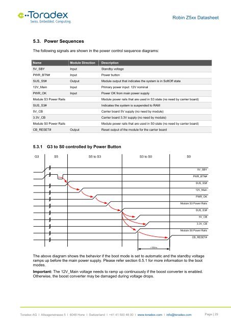
<strong>Robin</strong> <strong>Z5xx</strong> <strong>Datasheet</strong>5.3. Power SequencesThe following signals are shown in the power control sequence diagrams:Name Module Direction Description5V_SBY Input Standby voltagePWR_BTN# Input Power buttonSUS_S5# Output Module output that indicates the system is in SoftOff state12V_Main Input Primary power input: 12V nominalPWR_OK Input Power OK from main power supplyModule S3 Power RailsModule power rails that are used in S3 state (no need by carrier board)SUS_S3#Indicates the system is suspended to RAM5V_CBCarrier board 5V supply (no need by module)3.3V_CBCarrier board 3.3V supply (no need by module)Module S0 Power RailsModule power rails that are used in S0 state (no need by carrier board)CB_RESET# Output Reset output of the module for the carrier board5.3.1 G3 to S0 controlled by Power ButtonG3 S5 S5 to S3 S3 to S0 S05V_SBYPWR_BTN#SUS_S5#12V_MainPWR_OKModule S3 Power RailsSUS_S3#5V_CB3.3V_CBModule S0 Power RailsCB_RESET#>100msThe above diagram shows the behavior if the boot mode is set to automatic and the standby voltageramps up before the main power supply. Please refer section 6.5.1 for more information to the bootmodes.Important: The 12V_Main voltage needs to ramp up continuously if the boost converter is enabled.Otherwise, the boost converter may be damaged during voltage drops.<strong>Toradex</strong> AG l Altsagenstrasse 5 l 6048 Horw l Switzerland l +41 41 500 48 00 l www.toradex.com l info@toradex.com Page | 29


