installed, high interrupt current rated, non-fused disconnect switch withthrough-the-door handle. Each circuit shall be equipped with factory-installedcompressor isolation circuit breakers.OPTION: The unit shall have a high short circuit rated panel with single pointpower connection to a factory-installed, high interrupt current rated, non-fuseddisconnect switch with through-the-door handle. Each circuit shall be equippedwith a factory-installed compressor isolation circuit breaker.The control system shall stage and load the compressors based on the leavingwater temperature. Equipment protection devices controlled by themicroprocessor shall include motor protection, high pressure, loss of refrigerant,loss of water flow, freeze protection, and low refrigerant pressure. Controlsshall include auto/stop switch, chilled water setpoint adjustment, anti-recycletimer, and digital display with water temperature and setpoint, operatingtemperatures and pressures, and diagnostic messages. The following featuresand functions shall be included:1. The control logic shall be designed to maximize operating efficiency andequipment life with protections for operation under unusual conditions.The system shall intelligently stage the unit to sustain leaving watertemperature precision and stability while minimizing compressor cycling.2. The following features and functions shall be included:a. Password protection for setpoint adjustment.b. Durable liquid crystal display (LCD) screen type, having minimum four20-character lines with 6 key input pad conveniently mounted on the unitcontroller. Default language and units of measure shall be English and I-P respectively. Messages shall be in plain English. Coded messages,LED indicators and LED displays are not acceptable.c. Remote reset of chilled water temperature using a 4-20mA signal.d. Soft-load operation, protecting the compressor by preventing full-loadoperation during the initial chilled fluid pull-down period.e. BAS communication through Open Choices. Optional modular pluginsthat enable the unit controller to communicate using standardizedprotocols such as LONTALK, Modbus and BACnet without aseparate gateway.f. Non-volatile program memory allowing auto-restart after a power failurewithout requiring a UPS (un-interruptible power supply).g. Recording of safety shutdowns, including date-and-time stamp withsystem temperatures and pressures. A minimum of six previousoccurrences shall be maintained in a revolving memory.h. Start-to-start and stop-to-start cycle timers, providing minimumcompressor off-time while maximizing motor protection.i. Lead-lag compressor staging for part-load operation by manual selectionor automatically by circuit run hours.j. Pro-active compressor unloading when selected operating parametersexceed design settings, such as high discharge pressure or lowevaporator pressure.k. Diagnostic monitoring of unit operation, providing a pre-alarm signal inadvance of a potential shutdown, allowing time for corrective action.H. The following options are to be included:Chilled water flow switch to be field mounted in the chilled water line andfield wired to terminals in the control panel.58 WGS 130A – 190A Catalog WGS-1
Rubber-In-Shear OR spring vibration isolators for field installation perplans.PART 3 - EXECUTIONCompressor acoustical enclosure for sound reduction.3.01 INSTALLATIONA. Install in strict accordance with manufacturer’s requirements, shop drawings, andcontract documents.B. Adjust and level chiller in alignment on supports.C. Coordinate electrical installation with electrical contractor.D. Coordinate controls with control contractor.E. Provide all appurtenances required to ensure a fully operational and functionalchiller.3.02 START-UPA. Ensure proper charge of refrigerant and oil.B. Provide testing, and starting of machine, and instruction to the Owner in its properoperation and maintenance.Catalog WGS-1 WGS 130A – 190A 59
- Page 1 and 2:
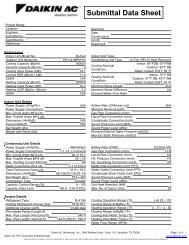
Water-Cooled Screw Compressor Chill
- Page 3 and 4:
IntroductionThe WGS water-cooled sc
- Page 5 and 6:
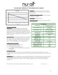
phase-out date. It has the best tox
- Page 7 and 8: Part Load EfficienciesPart load eff
- Page 9 and 10: Superior discharge pressure control
- Page 11: BACnet certification pendingProtoco
- Page 15 and 16: Selection ProcedureNormally the req
- Page 17 and 18: Performance Adjustment FactorsEthyl
- Page 19 and 20: Performance DataWGS-AW Water-Cooled
- Page 21 and 22: WGS-AW Part Load DataTable 10, Part
- Page 23 and 24: Table 12, WGS 130AA - WGS 190AA, S.
- Page 25 and 26: Table 14, WGS-AA Chillers Matched w
- Page 27 and 28: Figure 9, Condenser Pressure Drop W
- Page 29 and 30: Table 16, WGS 130AW - WGS 190AW, Wa
- Page 31 and 32: Table 20, WGS 130AW - 190AW, Water-
- Page 33 and 34: Table 22, WGS 130-190, Remote Conde
- Page 35 and 36: Table 26, WGS 130AA - 190AA, Remote
- Page 37 and 38: Field Wiring DiagramsFigure 10, WGS
- Page 39 and 40: Physical DataWGS-AW, Water-CooledTa
- Page 41 and 42: Dimensional DataWGS-AW Water-Cooled
- Page 43 and 44: WGS-AA Remote CondenserFigure 14, D
- Page 45 and 46: Figure 15, Sound EnclosureSound Red
- Page 47 and 48: Water-cooled condensers can be pipe
- Page 49 and 50: Table 33, Recommended Refrigerant P
- Page 51 and 52: Optional FeaturesControls/Instrumen
- Page 53 and 54: UnitSuction Shut-0ff ValvesA suctio
- Page 55 and 56: 1.06 WARRANTYThe equipment manufact
- Page 57: D. Evaporator: The evaporator shall
- Page 61 and 62: 1.06 WARRANTYThe equipment manufact
- Page 63 and 64: and have ANSI B9.1 pressure relief
- Page 65 and 66: All communication from the chiller
- Page 68: Daikin McQuay Training and Developm