TL-PA551 AV500+ Powerline Adapter with AC Pass Through - TP-Link
TL-PA551 AV500+ Powerline Adapter with AC Pass Through - TP-Link
TL-PA551 AV500+ Powerline Adapter with AC Pass Through - TP-Link
- No tags were found...

Create successful ePaper yourself
Turn your PDF publications into a flip-book with our unique Google optimized e-Paper software.
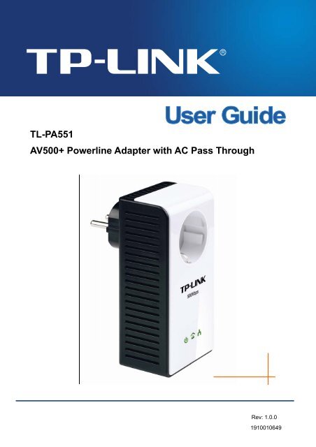
<strong>TL</strong>-<strong>PA551</strong><strong>AV500+</strong> <strong>Powerline</strong> <strong>Adapter</strong> <strong>with</strong> <strong>AC</strong> <strong>Pass</strong> <strong>Through</strong>Rev: 1.0.01910010649
COPYRIGHT & TRADEMARKSSpecifications are subject to change <strong>with</strong>out notice.is a registered trademark of<strong>TP</strong>-LINK TECHNOLOGIES CO., LTD. Other brands and product names are trademarks or registeredtrademarks of their respective holders.No part of the specifications may be reproduced in any form or by any means or used to make anyderivative such as translation, transformation, or adaptation <strong>with</strong>out permission from <strong>TP</strong>-LINKTECHNOLOGIES CO., LTD. Copyright © 2012 <strong>TP</strong>-LINK TECHNOLOGIES CO., LTD. All rightsreserved.http://www.tp-link.comCE Mark WarningThis is a class B product. In a domestic environment, this product may cause radio interference, in whichcase the user may be required to take adequate measures.Продукт сертифіковано згідно с правилами системи УкрСЕПРО на відповідність вимогамнормативних документів та вимогам, що передбачені чинними законодавчими актами України.
<strong>TP</strong>-LINK TECHNOLOGIES CO., LTDDECLARATION OF CONFORMITYFor the following equipment:Product Description: <strong>AV500+</strong> <strong>Powerline</strong> <strong>Adapter</strong> <strong>with</strong> <strong>AC</strong> <strong>Pass</strong> <strong>Through</strong>Model No.: <strong>TL</strong>-<strong>PA551</strong>Trademark: <strong>TP</strong>-LINKWe declare under our own responsibility that the above products satisfy all the technical regulationsapplicable to the product <strong>with</strong>in the scope of Council Directives:Directives 2004 / 108 / EC, Directives 2006 / 95 / EC, Directives 2011/65/EUThe above product is in conformity <strong>with</strong> the following standards or other normative documents:EN 55022:2010EN 55024:2010EN 61000-3-2:2006+A1:2009+A2:2009EN 61000-3-3:2008EN 50412-2-1:2005EN 60950-1:2006+A11:2009+A1:2010The product carries the CE MarkPerson is responsible for marking this declaration:Yang HongliangProduct Manager of International BusinessDate of issue: 2012<strong>TP</strong>-LINK TECHNOLOGIES CO., LTD.Building 24 (floors 1, 3, 4, 5), and 28 (floors 1-4) Central Science and Technology Park, ShennanRd, Nanshan, Shenzhen, China
<strong>TL</strong>-<strong>PA551</strong><strong>AV500+</strong> <strong>Powerline</strong> <strong>Adapter</strong> <strong>with</strong> <strong>AC</strong> <strong>Pass</strong> <strong>Through</strong>Package ContentsThe <strong>AV500+</strong> <strong>Powerline</strong> <strong>Adapter</strong> <strong>with</strong> <strong>AC</strong> <strong>Pass</strong> <strong>Through</strong> package contains the following items:‣ One <strong>AV500+</strong> <strong>Powerline</strong> <strong>Adapter</strong> <strong>with</strong> <strong>AC</strong> <strong>Pass</strong> <strong>Through</strong> (There are two powerline adapters in StarterKit)‣ One RJ-45 Cable (There are two RJ-45 Cables in Starter Kit)‣ One Quick Installation Guide‣ One Resource CD (Management Utility and User Guide) Note:Make sure that the package contains the above items. If any of the above items are damaged or missing,please contact your dealer immediately.ConventionsThe powerline adapter or <strong>AV500+</strong> <strong>Powerline</strong> <strong>Adapter</strong> <strong>with</strong> <strong>AC</strong> <strong>Pass</strong> <strong>Through</strong> mentioned in this guide stands for<strong>TL</strong>-<strong>PA551</strong> <strong>AV500+</strong> <strong>Powerline</strong> <strong>Adapter</strong> <strong>with</strong> <strong>AC</strong> <strong>Pass</strong> <strong>Through</strong> <strong>with</strong>out any explanation.1
<strong>TL</strong>-<strong>PA551</strong><strong>AV500+</strong> <strong>Powerline</strong> <strong>Adapter</strong> <strong>with</strong> <strong>AC</strong> <strong>Pass</strong> <strong>Through</strong>Chapter 1 IntroductionThis device is an <strong>AV500+</strong> <strong>Powerline</strong> <strong>Adapter</strong> <strong>with</strong> <strong>AC</strong> <strong>Pass</strong> <strong>Through</strong> which transforms your house’sexisting electrical wiring into a ubiquitous networking infrastructure. Simply plug this <strong>AV500+</strong> <strong>Powerline</strong><strong>Adapter</strong> <strong>with</strong> <strong>AC</strong> <strong>Pass</strong> <strong>Through</strong> into an ordinary <strong>AC</strong> power outlet which will easily extend yourCable/xDSL broadband connection or existing Ethernet (LAN) network to any other electrical outlet inany room of a house <strong>with</strong>out the need of any new cabling.This <strong>Powerline</strong> <strong>Adapter</strong> supports up to 500Mbps data rate over the existing household power circuit.With data rates of 500Mbps, full multimedia application can easily be supported throughout the wholehouse in addition to Internet access. This Mini <strong>Powerline</strong> <strong>Adapter</strong> uses the existing power lines installedin a home as a path to transmit digital data, voice, audio and video between devices.To ensure data communication’s security and multimedia applications, this Mini <strong>Powerline</strong> <strong>Adapter</strong>support built-in 128-bit AES encryption.The new <strong>Powerline</strong> <strong>Adapter</strong> <strong>TL</strong>-<strong>PA551</strong> from <strong>TP</strong>-LINK provides extra convenience and betterperformance for your home network <strong>with</strong> its integrated electrical socket and mains filer. The commonproblem of wasting an electrical outlet is solved and additional terminal devices or multiple sockets canbe connected to the adapter just like to a normal wall socket. What’s more, the data transmission in thenetwork can be significantly improved by the integrated mains filter.With minimum setup, you can installand use this Mini <strong>Powerline</strong> <strong>Adapter</strong> <strong>with</strong>in minutes. The adapter adds two useful functions.1. Existing connection <strong>with</strong> a new unassociated device added via the Pair Button.2. Reset to default setting via the Management Utility.1.1 System Requirementa) At least two <strong>AC</strong> 100V ~ 240V (50~60Hz) power outlets <strong>with</strong> standard home power wiringb) A computer <strong>with</strong> the following:‣ Operating System <strong>with</strong> TCP/IP installed‣ Pentium III compatible processor and above‣ Ethernet LAN card installed <strong>with</strong> TCP/IP protocol‣ 64 MB RAM or more‣ 50 MB of free disk space (Minimum)‣ CD-ROM Drive1.2 Important Safety Instructions1. Do not open this product or attempt to service it; it may expose you to dangerous high voltage orother risks.2. Do not operate this product near water.3. Do not place or operate this product near a radiator or a heat register.4. Do not expose this product to dampness, dust or corrosive liquids.5. Do not connect this product or disconnect it from a wall socket during a lightning or a thunderstorm6. Do not block the ventilation slots of this product, for insufficient airflow may harm it.7. Do not put anything on this product.8. Plug this product directly into a wall socket (100V~240V, 50~60Hz). Do not use an extension cord2
<strong>TL</strong>-<strong>PA551</strong><strong>AV500+</strong> <strong>Powerline</strong> <strong>Adapter</strong> <strong>with</strong> <strong>AC</strong> <strong>Pass</strong> <strong>Through</strong>between this product and the <strong>AC</strong> power source.9. When plugging this product into a wall socket, make sure that the electrical socket is not damaged,and that there is no gas leakage.10. Place the connecting cables properly so that people won’t stumble or walk on it.11. This product should be operated from the type of power indicated on the marking label. If you are notsure of the type of power available, consult the qualified technician.12. Unplug this product from the mains and refer the product to qualified service personnel for thefollowing conditions:‣ If liquid has been spilled on the product‣ If the product has been exposed to rain or water13. Unplug this product from the wall socket before cleaning. Use a damp cloth for cleaning. Do not useliquid cleaners or aerosol cleaners.14. The specification of the fuse is T2.5AL250V. To avoid damage, please do not change the fuse.15. The Operating temperature is 0 ℃ ~40 ℃ (32 ℉ ~104 ℉ ).16. The Storage temperature is -40 ℃ ~70℃ (-40 ℉ ~158 ℉ ).1.3 LED IndicatorThe LED indicator displays information about the device’s status.3
<strong>TL</strong>-<strong>PA551</strong><strong>AV500+</strong> <strong>Powerline</strong> <strong>Adapter</strong> <strong>with</strong> <strong>AC</strong> <strong>Pass</strong> <strong>Through</strong> Note:Item Status IndicationPower LED<strong>Powerline</strong> LEDEthernet LEDOnBlinkingOffGreenOrangeRedOffOnBlinkingOffThe adapter is on.The adapter is in power-saving mode or in pairingprocedure.The adapter is off.Data rate is more than or equal to 80Mbps.Data rate is between 48Mbps and 80Mbps.Data rate is less than or equal to 48Mbps.The adapter isn’t connected to any powerline network oris in power-saving mode.The Ethernet port is connected, but there is no databeing transferred.The Ethernet port is transferring data.The Ethernet port isn’t connected.5 minutes after the device connected to the adapter is turned off, the adapter will automatically switch tothe power-saving Mode.1.4 Physical InterfaceThere are four physical interfaces on this Mini <strong>Powerline</strong> <strong>Adapter</strong>.Integrated Electrical SocketPower PlugEthernet PortPair Button4
<strong>TL</strong>-<strong>PA551</strong><strong>AV500+</strong> <strong>Powerline</strong> <strong>Adapter</strong> <strong>with</strong> <strong>AC</strong> <strong>Pass</strong> <strong>Through</strong>InterfaceEthernet PortPower Plug*Pair ButtonIntegrated ElectricalSocketDescriptionIt is a 10/100Mbps Ethernet port on the AV adapter for connecting itto the PC or the broadband device <strong>with</strong> the network cable.A Power Plug connected to any 100V ~ 240V <strong>AC</strong> (50~60Hz) powersocketPair buttons are used to secure a powerline network. To secureyour network, please follow the steps below. Firstly, plug in a newadapter, and press its pair button for 1 second; then plug in anotheradapter and press its pair button for 1 second as well. The twobuttons should be pressed <strong>with</strong>in 2 minutes of each other. Afterthat, wait about 60 seconds so that the two adapters can finishconnecting.The integrated electrical socket allows additional devices ormultiple sockets to be connected to the adapter just like to a normalwall socket. No electrical socket is lost.* The provided power plug may differ from the picture due to different regional power specifications. Herewe take the EU version as an example. Note:1. If you press the pair button for more than 10 seconds, the powerline adapter will leave the networkwhich it has joined and its new network name assumes a random value. The Power LED turns offwhen it disconnects from the powerline network.2. For detailed information about the pair button, please refer to Charpter 5 Advanced Feature: How toUse the Pair Buttons.5
<strong>TL</strong>-<strong>PA551</strong><strong>AV500+</strong> <strong>Powerline</strong> <strong>Adapter</strong> <strong>with</strong> <strong>AC</strong> <strong>Pass</strong> <strong>Through</strong>Chapter 2 Connecting Mechanism2.1 IntroductionThe <strong>Powerline</strong> <strong>Adapter</strong> supports up to 500Mbps data rate. With this high speed connection rate, this<strong>Powerline</strong> <strong>Adapter</strong> allows you to set up a high speed home network by using your home existingelectrical wiring. Simply plug this <strong>Powerline</strong> <strong>Adapter</strong> into an ordinary power outlet to extend yourCable/xDSL broadband connection or existing LAN network to any other electrical outlet in any room ofyour house.Note that this <strong>Powerline</strong> <strong>Adapter</strong> works in pairs. You need to plug one <strong>Powerline</strong> <strong>Adapter</strong> into a poweroutlet for each computer and connect the <strong>Powerline</strong> <strong>Adapter</strong> to the computer’s LAN card <strong>with</strong> anEthernet cable; you will also need another <strong>Powerline</strong> <strong>Adapter</strong> connected to your Cable/xDSL broadbandso as to extend your broadband connection or Internet surfing. With clean power line, the distancebetween two <strong>Powerline</strong> <strong>Adapter</strong>s can reach 300 meters at lease, but the actual distance may vary due tothe environment.Section below describes the connection instructions and hardware connection mechanism.2.2 Connection InstructionTo ensure the optimum performance of the <strong>Powerline</strong> <strong>Adapter</strong> and significantly improve the transmissioncapacity of the network, we recommend that you comply <strong>with</strong> the following connection rules:• Plug the <strong>Powerline</strong> <strong>Adapter</strong> directly into a wall socket but not the multiple sockets.• To take full advantage of the filter function of the <strong>Powerline</strong> <strong>Adapter</strong> and to improve datatransmission in the network, always plug the multiple sockets into the integrated electrical socket ofthe <strong>Powerline</strong> <strong>Adapter</strong>.6
<strong>TL</strong>-<strong>PA551</strong><strong>AV500+</strong> <strong>Powerline</strong> <strong>Adapter</strong> <strong>with</strong> <strong>AC</strong> <strong>Pass</strong> <strong>Through</strong>2.3 Hardware Connection – ComputerFor those computers you wish to be networked by <strong>Powerline</strong> <strong>Adapter</strong>, each of the computers must beproperly connected <strong>with</strong> a <strong>Powerline</strong> <strong>Adapter</strong> through an Ethernet (RJ-45) cable.Following are the steps to properly connect the <strong>Powerline</strong> <strong>Adapter</strong> to your computer:1. Connect one end of the provided Ethernet (RJ-45) cable to the <strong>Powerline</strong> <strong>Adapter</strong>’s Ethernet port.2. Connect the other end of the Ethernet (RJ-45) cable to you computer’s LAN port.3. Plug the <strong>Powerline</strong> <strong>Adapter</strong> into a wall socket next to the computer.4. Turn on your computer.5. Check and confirm that the Power LED and Ethernet LED on the <strong>Powerline</strong> <strong>Adapter</strong> areON.The hardware connection mechanism is shown below: Note:Do not connect the <strong>Powerline</strong> adapter to any extension lead, power strip, extension cord or surgeprotector, as these may degrade the network performance.2.4 Hardware Connection – InternetThis section describes how to connect the <strong>Powerline</strong> <strong>Adapter</strong> into your existing ADSL broadbandconnection via ADSL Ethernet port. Follow the procedures described below to connect the <strong>Powerline</strong><strong>Adapter</strong> to your ADSL broadband connection:1. Connect one end of the provided Ethernet (RJ-45) cable to the <strong>Powerline</strong> <strong>Adapter</strong>’s Ethernet port.2. Connect the other end of the Ethernet (RJ-45) cable to an available Ethernet port of your ADSLbroadband Router.3. Plug the <strong>Powerline</strong> <strong>Adapter</strong> into a wall socket next to the computer.4. Turn on your computer.5. Check and confirm that the Power LED , Ethernet LED , and <strong>Powerline</strong> LED on the<strong>Powerline</strong> <strong>Adapter</strong> are ON.7
<strong>TL</strong>-<strong>PA551</strong><strong>AV500+</strong> <strong>Powerline</strong> <strong>Adapter</strong> <strong>with</strong> <strong>AC</strong> <strong>Pass</strong> <strong>Through</strong>The hardware connection mechanism is shown below: Note:Where the MAINS plug or an appliance coupler is used as the disconnected device, the disconnectdevice shall remain readily operable. The idle wall sockets or electrical outlets in your householdelectrical circuit can be used normally <strong>with</strong>out interference from the network.8
<strong>TL</strong>-<strong>PA551</strong><strong>AV500+</strong> <strong>Powerline</strong> <strong>Adapter</strong> <strong>with</strong> <strong>AC</strong> <strong>Pass</strong> <strong>Through</strong>Chapter 3 Installing Management UtilityPlease verify that no other <strong>Powerline</strong> <strong>Adapter</strong> or any Encryption Management Utilities are installedbefore installing the provided software. If other <strong>Powerline</strong> Utilities are installed, uninstall them and restartyour personal computer before installing this provided software. Note:To install Management Utility, please make sure that WinPcap 4.1.2 has been installed in your computer.Otherwise, a window will pop up for you to install WinPcap 4.1.2.Take the following procedures to properly install the provided Management Utility:Step 1: Insert the Resource CD into your CD-ROM drive, and then the following Setup Wizard willautomatically pop up on your computer’s screen.Step 2:Select 500Mbps <strong>Powerline</strong> and click Management Utility, and then the program installationprocess will carry out and copy all the necessary files to your system.9
<strong>TL</strong>-<strong>PA551</strong><strong>AV500+</strong> <strong>Powerline</strong> <strong>Adapter</strong> <strong>with</strong> <strong>AC</strong> <strong>Pass</strong> <strong>Through</strong>10
<strong>TL</strong>-<strong>PA551</strong><strong>AV500+</strong> <strong>Powerline</strong> <strong>Adapter</strong> <strong>with</strong> <strong>AC</strong> <strong>Pass</strong> <strong>Through</strong>11
<strong>TL</strong>-<strong>PA551</strong><strong>AV500+</strong> <strong>Powerline</strong> <strong>Adapter</strong> <strong>with</strong> <strong>AC</strong> <strong>Pass</strong> <strong>Through</strong>Step 3:After the installation, a shortcut to the “<strong>Powerline</strong> Utility” application icon is provided on thewindows desktop.12
<strong>TL</strong>-<strong>PA551</strong><strong>AV500+</strong> <strong>Powerline</strong> <strong>Adapter</strong> <strong>with</strong> <strong>AC</strong> <strong>Pass</strong> <strong>Through</strong>Chapter 4 Using the Management UtilityAfter you’d successfully installed the <strong>Powerline</strong> <strong>Adapter</strong> hardware and Management Utility software, youcan set up or configure the devices according to your need.This <strong>Powerline</strong> Utility enables the users to identify powerline devices on the powerline network,measures data rate performance and ensures privacy by setting user defined secure powerlinenetworks.Double click on the icon “ ” from your windows desktop, the following screen will display. ThisManagement Utility consists of a four property tabs, “Status”, “Network”, “Advanced” and “System”.4.1 StatusThe Status tab shows information of the powerline adapter connected to the current computer where theManagement Utility is running. On this page, you can also set its network name.13
<strong>TL</strong>-<strong>PA551</strong><strong>AV500+</strong> <strong>Powerline</strong> <strong>Adapter</strong> <strong>with</strong> <strong>AC</strong> <strong>Pass</strong> <strong>Through</strong>‣ M<strong>AC</strong> Address: Displays the M<strong>AC</strong> address of the powerline adapter connected to the currentcomputer where this management utility is running.‣ Network Name: Displays the network name of the current network or you can give a name for thenetwork in which the powerline adapter is. By default, the network name is HomeplugAV.‣ Use Default (HomePlugAV): Check the box before this item to use the default network name.‣ Apply: Click the Apply button to make the setting effective.‣ <strong>Pass</strong>word: Displays the password of the current powerline adapter. Every powerline adapter has itsown password by default, which can be also found on the back of the adapter.‣ Firmware: Displays the current firmware version used by the adapter.‣ Refresh: Click the Refresh button to update the information.4.1.1 Set Local Device’s Network NameTo set the local device’s network name, please take the following steps:(1) Click Status tab to display the Status tab window.(2) Enter a name for the current network using 4~23 characters. Or you can check the Use Default(HomePlugAV) to use the default name as the network name. By default, the network name isHomeplugAV.(3) Click the Apply button to make the settings take effect.4.2 NetworkThe Network tab window shows information of all the powerline adapters found on the current logicalnetwork. Furthermore, here you can change the Name of the listed powerline adapters as well as add14
<strong>TL</strong>-<strong>PA551</strong><strong>AV500+</strong> <strong>Powerline</strong> <strong>Adapter</strong> <strong>with</strong> <strong>AC</strong> <strong>Pass</strong> <strong>Through</strong>another device to the current network.‣ Type: Displays the type of the remote device found in the network.‣ Name: Displays the name of the remote device found in the network. You can change its namefollowing two steps: select the desired adapter and click the Modify button.‣ M<strong>AC</strong> Address: Displays the M<strong>AC</strong> address of the remote device found in the network.‣ <strong>Pass</strong>word: Displays the supplied <strong>Powerline</strong> <strong>Adapter</strong>’s password (Initially left blank). To set the<strong>Powerline</strong> <strong>Adapter</strong> password (Which is required when creating a private network or managing all thedevices), select the device shown in the figure and click the Modify button. Follow the pop-up dialogbox to complete your password setting.‣ Rate: Shows the current transmission rate of the <strong>Powerline</strong> <strong>Adapter</strong>.‣ Rescan: Click the “Rescan” button to perform an immediate search of the remote <strong>Powerline</strong><strong>Adapter</strong>. The Management Utility will automatically perform the scanning process and update thedisplay every few seconds by default.‣ Option: Select the device and click the Modify button to display a configuration dialog. There youcan change the corresponding adapter’s name and enter its password for future configuration.4.2.1 Rename the Remote Device/Enter <strong>Pass</strong>wordYou can change the name of the remote adapter to an easy-to-remember one. Additionally, you canselect the desired adapter and enter its password (Take note of the password format) so as to set thenetwork name of this device on System configuration homepage. To change the name of the remoteadapter or enter its password, please follow the steps below:15
<strong>TL</strong>-<strong>PA551</strong><strong>AV500+</strong> <strong>Powerline</strong> <strong>Adapter</strong> <strong>with</strong> <strong>AC</strong> <strong>Pass</strong> <strong>Through</strong>(1) Select the desired device and click the Modify button to display the following dialog.(2) Enter a new name for the selected adapter and enter its password (Take note of the passwordformat). The password can be found on the back of adapter.(3) Click the Save button to make the settings effective. Note:<strong>Pass</strong>word is unnecessary to enter for renaming.4.2.2 Add DeviceYou can add a remote <strong>Powerline</strong> <strong>Adapter</strong> to your network that is not in the displayed list. You aresuggested to locate the passwords for all <strong>Powerline</strong> <strong>Adapter</strong>s you wish to manage and add them to thelocal logical network by clicking the Add button.Click the Add button to display the following dialog box. This dialog box allows you to enter both theselected device’s name and password. Note that the <strong>Powerline</strong> <strong>Adapter</strong> must be present on the powergrid in order to activate the set password and be added to the local network.Enter your Device Name and <strong>Pass</strong>word (Take note to the password format) and click the Save buttonafter setup.16
<strong>TL</strong>-<strong>PA551</strong><strong>AV500+</strong> <strong>Powerline</strong> <strong>Adapter</strong> <strong>with</strong> <strong>AC</strong> <strong>Pass</strong> <strong>Through</strong>4.3 AdvancedThe third tab window labeled “Advanced” is for Quality of Service. With the proper configuration, thelimit bandwidth can be took full advantage. QoS requirements are different for various data types such asstreaming video or music, voice and raw data. To provide higher QoS for streaming data, priority levelscan be set using tags at the beginning of data frames. Virtual Local Area Network (Vlan) 802.1p prioritytags on Ethernet frames are used to specify 8 (0~7) levels of “user priority”. Homeplug AV powerlineallows for 4 levels of Channel Access Priority CAP 0-3)). Therefore, the 8 levels of VLAN Ethernet tagsmust be mapped to the 4 levels of CAP priority, where CAP 3 is the highest priority and CAP 0 is thelowest. CAP 3 priority might be used for voice and network management frames, CAP 2 is used forstreaming video while CAP 1 and CAP 0 are used for data. Mapping VLAN tags to CAP levels is easilydone using the VLAN Priority Mapping function on the QoS tab window.‣ Simple Application Mapping: The group allows you to choose what type of traffic <strong>with</strong> the highestuser priority you will use your local HomePlug device for by pitching one of the following radios.Please select the radio type according to your demand.‣ Advanced Priority Mapping: The group sets VLAN priority to CAP mapping and default priority.Note that in HomePlug, CAP 3 is the highest priority while CAP 0 is the lowest priority. The valuesshown in VLAN Tags Priority are the default settings for the first running.4.4 SystemThe System tab window is for some basic settings of the adapter. On this tab window, you can upgradethe firmware to the latest version, reset the adapter’s settings to the factory defaults and configure alladapters’ network names.17
<strong>TL</strong>-<strong>PA551</strong><strong>AV500+</strong> <strong>Powerline</strong> <strong>Adapter</strong> <strong>with</strong> <strong>AC</strong> <strong>Pass</strong> <strong>Through</strong>4.4.1 Upgrade FirmwareClick the Upgrade Firmware button to upgrade the version of the firmware for the adapter and thefollowing dialog will pop up.• NVM: None-volatile memory. It is used for upgrading the firmware.• PIB: Parameter Information Block. It contains configuration values that establish devicenetwork identity, general capabilities and operational modes.If you want to upgrade the version of firmware for the device, please select appropriate Firmware andPIB files together. New firmware versions and PIB files are posted at www.tp-link.com and can bedownloaded for free.18
<strong>TL</strong>-<strong>PA551</strong><strong>AV500+</strong> <strong>Powerline</strong> <strong>Adapter</strong> <strong>with</strong> <strong>AC</strong> <strong>Pass</strong> <strong>Through</strong> Note:The parameter information of PIB will restore to the factory defaults after resetting the PLC.To upgrade the device's firmware, follow these instructions:1. Download PIB file and firmware upgrade file from the <strong>TP</strong>-LINK website (www.tp-link.com).2. Enter the path name or click to select the downloaded files on the computer into thecorresponding blanks.3. Click the OK button. Note:Do not turn off the device while the firmware is being upgraded. The device will reboot after theUpgrading has been finished.4.4.2 Reset DeviceThis Management Utility allows you to reset the <strong>Powerline</strong> <strong>Adapter</strong> to its default settings.• Reset Local Device: Click this button to reset the settings of the local <strong>Powerline</strong> <strong>Adapter</strong> deviceonly.• Reset All Devices: Click this button to reset the settings of all devices that appear on theNetwork configuration homepage whose Device’s <strong>Pass</strong>word had been entered for the samelogical network.4.4.3 Set All Devices’ Network NameThe Set All Devices’ Network Name button allows you to change the logical network of all devices thatappear on the Network configuration homepage whose Device’s <strong>Pass</strong>word had been entered for thesame logical network. A dialog window will appear to report the success of this operation.All <strong>Powerline</strong> devices are shipped using a default logical network (network name), which is normally“HomePlugAV”.To set all devices’ network name, please type the name in the field and click the Set Network Name toapply the setting. Note:Every Mini <strong>Powerline</strong> <strong>Adapter</strong> on your home network MUST have the same Network <strong>Pass</strong>word forconnectivity to be established throughout your home.19
<strong>TL</strong>-<strong>PA551</strong><strong>AV500+</strong> <strong>Powerline</strong> <strong>Adapter</strong> <strong>with</strong> <strong>AC</strong> <strong>Pass</strong> <strong>Through</strong>Chapter 5 Advanced Feature: How to Use the Pair Buttons5.1 Pair (Secure <strong>with</strong> 128 bits-AES)The Homeplug AV standard uses 128-bit AES (Advanced Encryption Standard) to safely transmit databetween powerline adapters. For the powerline adapters to communicate <strong>with</strong> each other they all needto use the same Network Membership Key (NMK). Otherwise, they cannot unscramble the encrypteddata sent in the powerline network.The Pair button allows you to set up a secure powerline connection <strong>with</strong> another HomePlug AVcompliant powerline devices which also support the Pair feature.5.2 Set Up a Secured <strong>Powerline</strong> AV Network <strong>with</strong> the Pair ButtonYou can connect a number of devices on a powerline network, but you can only use the Pair button ontwo devices at a time.Create a secured <strong>Powerline</strong> network using the Pair button:Step 1. Press the Pair button of <strong>Powerline</strong> adapter A for one second, the Power LED will start flashing.Step 2. Press the Pair button of <strong>Powerline</strong> adapter B for one second, the Power LED will start flashing.(This must be done <strong>with</strong>in 120 seconds after pressing the pair button of powerline adapter A.)Step 3. Wait for about 60 seconds while your <strong>Powerline</strong> adapter A and B are connecting. The PowerLED on both adapters will stop flashing and become solid light when the connection is made.20
<strong>TL</strong>-<strong>PA551</strong><strong>AV500+</strong> <strong>Powerline</strong> <strong>Adapter</strong> <strong>with</strong> <strong>AC</strong> <strong>Pass</strong> <strong>Through</strong>Join an existing secured <strong>Powerline</strong> AV Network:<strong>Powerline</strong> adapter A and <strong>Powerline</strong> adapter B form a HomeplugAV Network, <strong>Powerline</strong> adapter C wantsto join this network.Step 1.Step 2.Press and hold the Pair button on <strong>Powerline</strong> adapter C for one second.Press and hold the Pair button on <strong>Powerline</strong> adapter A/B for one second.(This step must be taken <strong>with</strong>in 120 seconds after step 1 is finished.)Step 3. Wait for about 60 seconds while your <strong>Powerline</strong> adapters are connecting. The Power LED on<strong>Powerline</strong> adapter A/B and C will stop flashing and become solid light when the connection ismade. Note:The sequence of Step 1 and Step 2 can be exchanged.Leave an existing secured <strong>Powerline</strong> AV Network:As the figure above shown, <strong>Powerline</strong> adapter A, B and C have formed a HomeplugAV Network. Theuser wants to remove one device (<strong>Powerline</strong> adapter A) from this network.Step 1. Press and hold the Pair button on <strong>Powerline</strong> adapter A for at least 10 seconds. <strong>Powerline</strong>adapter A will reset and restart. (The Power LED of <strong>Powerline</strong> adapter A will momentarilyextinguish during resetting, flash during restarting then illuminate steadily.)Step 2. Wait for the reset to complete.21
<strong>TL</strong>-<strong>PA551</strong><strong>AV500+</strong> <strong>Powerline</strong> <strong>Adapter</strong> <strong>with</strong> <strong>AC</strong> <strong>Pass</strong> <strong>Through</strong>Appendix A: TroubleshootingThe Troubleshooting provides answers to common problems regarding the <strong>Powerline</strong> <strong>Adapter</strong>.1. The Power LED does not light up.Ans. Check the following:a) Make sure that the <strong>Powerline</strong> <strong>Adapter</strong> is properly plugged into a power outlet.b) Make sure the power outlet is active (working) by plugging another electric device into it.c) Re-plug the <strong>Powerline</strong> <strong>Adapter</strong> to the power outlet again. If the Power LED still fails to light up,contact your local dealer for technical support.2. The Ethernet LED does not light up.Ans. Check the following:1. Make sure that the Ethernet cable (RJ-45) is properly connected to the <strong>Powerline</strong> <strong>Adapter</strong>’sEthernet port.2. Make sure that the other end of the Ethernet cable (RJ-45) is properly connected to thecomputer LAN card or to you Cable/xDSL Ethernet port.3. Make sure your computer LAN card is properly installed and configured.4. Make sure your Cable/xDSL broadband access is working and configured correctly.5. Contact your local dealer for technical support if the Ethernet LED still fails to light up after theabove procedures.3. The <strong>Powerline</strong> LED does not light up.Ans. Check the following:1. Double click to enable the Management Utility and click the “Rescan” tab under the Networkconfiguration homepage. The Management Utility will automatically detect all other <strong>Powerline</strong><strong>Adapter</strong> on your power line network.2. Try to plug a second <strong>Powerline</strong> <strong>Adapter</strong> into a nearby power outlet and check whether the<strong>Powerline</strong> LED lights up or not.3. Contact your local dealer for technical support if the <strong>Powerline</strong> LED still fails to light up after theabove procedures.22
<strong>TL</strong>-<strong>PA551</strong><strong>AV500+</strong> <strong>Powerline</strong> <strong>Adapter</strong> <strong>with</strong> <strong>AC</strong> <strong>Pass</strong> <strong>Through</strong>Appendix B: SpecificationsGeneralStandardsModulation TechnologyData RateRangeLEDsInterfaceEncryptionHomePlug AV, IEEE802.3, IEEE802.3uOFDM, 1024/256/64/16/8-QAM, QPSK, BPSK and ROBO500Mbps300meters in housePower, <strong>Powerline</strong>, Ethernet1 Ethernet LAN Port, 1 Integrated Electrical Socket128-bit AESPower Consumption 5.4WPhysical and EnvironmentDimensions (L×W×H)126×64×42 mm (exclude power plug)126×64×79 mm (include power plug)Operating Temperature 0℃~40℃ (32℉~104℉)Operating Humidity10%~90%RH, Non-condensing23