TL-WR841N TL-WR841ND 300Mbps Wireless N Router - TP-Link
TL-WR841N TL-WR841ND 300Mbps Wireless N Router - TP-Link
TL-WR841N TL-WR841ND 300Mbps Wireless N Router - TP-Link

Create successful ePaper yourself
Turn your PDF publications into a flip-book with our unique Google optimized e-Paper software.
<strong>TL</strong>-<strong>WR841N</strong><strong>TL</strong>-<strong>WR841N</strong>D<strong>300Mbps</strong> <strong>Wireless</strong> N <strong>Router</strong>Rev: 3.2.01910010568
COPYRIGHT & TRADEMARKSSpecifications are subject to change without notice.is a registered trademarkof <strong>TP</strong>-LINK TECHNOLOGIES CO., LTD. Other brands and product names are trademarks orregistered trademarks of their respective holders.No part of the specifications may be reproduced in any form or by any means or used to make anyderivative such as translation, transformation, or adaptation without permission from <strong>TP</strong>-LINKTECHNOLOGIES CO., LTD. Copyright © 2012 <strong>TP</strong>-LINK TECHNOLOGIES CO., LTD. All rightsreserved.http://www.tp-link.comFCC STATEMENTThis equipment has been tested and found to comply with the limits for a Class B digital device,pursuant to part 15 of the FCC Rules. These limits are designed to provide reasonable protectionagainst harmful interference in a residential installation. This equipment generates, uses and canradiate radio frequency energy and, if not installed and used in accordance with the instructions,may cause harmful interference to radio communications. However, there is no guarantee thatinterference will not occur in a particular installation. If this equipment does cause harmfulinterference to radio or television reception, which can be determined by turning the equipment offand on, the user is encouraged to try to correct the interference by one or more of the followingmeasures:• Reorient or relocate the receiving antenna.• Increase the separation between the equipment and receiver.• Connect the equipment into an outlet on a circuit different from that to which the receiveris connected.• Consult the dealer or an experienced radio/ TV technician for help.This device complies with part 15 of the FCC Rules. Operation is subject to the following twoconditions:1) This device may not cause harmful interference.2) This device must accept any interference received, including interference that may causeundesired operation.Any changes or modifications not expressly approved by the party responsible for compliancecould void the user’s authority to operate the equipment.Note: The manufacturer is not responsible for any radio or tv interference caused by unauthorizedmodifications to this equipment. Such modifications could void the user’s authority to operate theequipment.
FCC RF Radiation Exposure StatementThis equipment complies with FCC RF radiation exposure limits set forth for an uncontrolledenvironment. This device and its antenna must not be co-located or operating in conjunction withany other antenna or transmitter.“To comply with FCC RF exposure compliance requirements, this grant is applicable to onlyMobile Configurations. The antennas used for this transmitter must be installed to provide aseparation distance of at least 20 cm from all persons and must not be co-located or operating inconjunction with any other antenna or transmitter.”CE Mark WarningThis is a Class B product. In a domestic environment, this product may cause radio interference,in which case the user may be required to take adequate measures.National restrictionsThis device is intended for home and office use in all EU countries (and other countries followingthe EU directive 1999/5/EC) without any limitation except for the countries mentioned below:Country Restriction Reason/remarkBulgariaNoneGeneral authorization required for outdoor use andpublic serviceFranceOutdoor use limited to 10mW e.i.r.p. within the band2454-2483.5 MHzMilitary Radiolocation use. Refarming of the 2.4 GHzband has been ongoing in recent years to allow currentrelaxed regulation. Full implementation planned 2012ItalyNoneIf used outside of own premises, general authorization isrequiredLuxembourgNoneGeneral authorization required for network and servicesupply(not for spectrum)NorwayImplementedThis subsection does not apply for the geographical areawithin a radius of 20 km from the centre of Ny-ÅlesundRussian Federation None Only for indoor applicationsNote: Please don’t use the product outdoors in France.
This device has been designed to operate with the antennas listed below, and having a maximumgain of 5 dBi. Antennas not included in this list or having a gain greater than 5 dBi are strictlyprohibited for use with this device. The required antenna impedance is 50 ohms.To reduce potential radio interference to other users, the antenna type and its gain should be sochosen that the equivalent isotropically radiated power (e.i.r.p.) is not more than that permitted forsuccessful communication.Industry Canada StatementThis device complies with RSS-210 of the Industry Canada Rules. Operation is subject to thefollowing two conditions:(1)This device may not cause harmful interference, and(2)This device must accept any interference received, including interference that may causeundesired operation.IMPORTANT NOTE:Radiation Exposure Statement:This equipment complies with Canada radiation exposure limits set forth for an uncontrolledenvironment. This equipment should be installed and operated with minimum distance 20cmbetween the radiator & your body.Ce dispositif est conforme à la norme CNR-210 d’Industrie Canada applicable aux appareils radioexempts de licence. Son fonctionnement est sujet aux deux conditions suivantes:(1) Le dispositif ne doit pas produire de brouillage préjudiciable, et(2) Ce dispositif doit accepter tout brouillage reçu,y compris un brouillage susceptible deprovoquer un fonctionnement indésirable.NOTE IMPORTANTE:Déclaration d’exposition aux radiations:Cet équipement est conforme aux limites d’exposition aux rayonnements IC établies pour unenvironnement non contrôlé. Cet équipement doit être installé et utilisé avec un minimum de 20cm de distance entre la source de rayonnement et votre corps.Korea Warning Statements당해 무선설비는 운용중 전파혼신 가능성이 있음.NCC Notice經 型 式 認 證 合 格 之 低 功 率 射 頻 電 機 , 非 經 許 可 , 公 司 、 商 號 或 使 用 者 均 不 得 擅 自 變 更 頻 率 、 加 大 功率 或 變 更 原 設 計 之 特 性 及 功 能 。
低 功 率 射 頻 電 機 之 使 用 不 得 影 響 飛 航 安 全 及 干 擾 合 法 通 信 ; 經 發 現 有 干 擾 現 象 時 , 應 立 即 停 用 , 並改 善 至 無 干 擾 時 方 得 繼 續 使 用 。 前 項 合 法 通 信 , 指 依 電 信 法 規 定 作 業 之 無 線 電 通 信 。 低 功 率 射 頻 電機 須 忍 受 合 法 通 信 或 工 業 、 科 學 及 醫 療 用 電 波 輻 射 性 電 機 設 備 之 干 擾 。
<strong>TP</strong>-LINK TECHNOLOGIES CO., LTDDECLARATION OF CONFORMITYFor the following equipment:Product Description: <strong>300Mbps</strong> <strong>Wireless</strong> N <strong>Router</strong>Model No.: <strong>TL</strong>-<strong>WR841N</strong>/<strong>TL</strong>-<strong>WR841N</strong>DTrademark: <strong>TP</strong>-LINKWe declare under our own responsibility that the above products satisfy all the technicalregulations applicable to the product within the scope of Council Directives:Directives 1999/5/EC, Directives 2004/108/EC, Directives 2006/95/EC, Directives 1999/519/EC,Directives 2011/65/EUThe above product is in conformity with the following standards or other normative documentsETSI EN 300 328 V1.7.1: 2006ETSI EN 301 489-1 V1.8.1:2008& ETSI EN 301 489-17 V2.1.1:2009EN 55022:2006 +A1:2007EN 55024:1998+A1:2001+A2:2003EN 61000-3-2:2006+A1:2009+A2:2009EN 61000-3-3:2008EN60950-1:2006+A11:2009+A1:2010EN62311:2008The product carries the CE Mark:Person is responsible for marking this declaration:Yang HongliangProduct Manager of International BusinessDate of issue: 2012<strong>TP</strong>-LINK TECHNOLOGIES CO., LTD.Building 24 (floors 1, 3, 4, 5), and 28 (floors 1-4) Central Science and Technology Park,Shennan Rd, Nanshan, Shenzhen, China
CONTENTSPackage Contents.....................................................................................................1Chapter 1. Introduction.........................................................................................21.1 Overview of the <strong>Router</strong>............................................................................................... 21.2 Conventions ............................................................................................................... 31.3 Main Features ............................................................................................................ 31.4 Panel Layout .............................................................................................................. 41.4.1 The Front Panel.............................................................................................. 41.4.2 The Rear Panel .............................................................................................. 5Chapter 2. Connecting the <strong>Router</strong> .......................................................................62.1 System Requirements ................................................................................................ 62.2 Installation Environment Requirements...................................................................... 62.3 Connecting the <strong>Router</strong> ............................................................................................... 6Chapter 3. Quick Installation Guide.....................................................................83.1 TCP/IP Configuration ................................................................................................. 83.2 Quick Installation Guide ........................................................................................... 10Chapter 4. Configuring the <strong>Router</strong> ....................................................................164.1 Login ........................................................................................................................ 164.2 Status ....................................................................................................................... 164.3 Quick Setup.............................................................................................................. 184.4 QSS.......................................................................................................................... 184.5 Network .................................................................................................................... 254.5.1 LAN .............................................................................................................. 254.5.2 WAN ............................................................................................................. 254.5.3 MAC Clone ................................................................................................... 354.6 <strong>Wireless</strong> ................................................................................................................... 364.6.1 <strong>Wireless</strong> Settings.......................................................................................... 364.6.2 <strong>Wireless</strong> Security.......................................................................................... 394.6.3 <strong>Wireless</strong> MAC Filtering ................................................................................. 424.6.4 <strong>Wireless</strong> Advanced ....................................................................................... 454.6.5 <strong>Wireless</strong> Statistics......................................................................................... 464.7 DHCP ....................................................................................................................... 474.7.1 DHCP Settings ............................................................................................. 47- I -
4.7.2 DHCP Clients List ......................................................................................... 484.7.3 Address Reservation .................................................................................... 494.8 Forwarding ............................................................................................................... 504.8.1 Virtual Servers .............................................................................................. 504.8.2 Port Triggering .............................................................................................. 524.8.3 DMZ.............................................................................................................. 544.8.4 UPnP ............................................................................................................ 544.9 Security .................................................................................................................... 554.9.1 Basic Security............................................................................................... 564.9.2 Advanced Security........................................................................................ 574.9.3 Local Management ....................................................................................... 584.9.4 Remote Management ................................................................................... 594.10 Parental Control ....................................................................................................... 604.11 Access Control ......................................................................................................... 634.11.1 Rule .............................................................................................................. 634.11.2 Host .............................................................................................................. 664.11.3 Target............................................................................................................ 684.11.4 Schedule....................................................................................................... 704.12 Advanced Routing.................................................................................................... 724.12.1 Static Routing ............................................................................................... 724.12.2 System Routing Table................................................................................... 734.13 Bandwidth Control .................................................................................................... 744.13.1 Control Settings ............................................................................................ 744.13.2 Rules List...................................................................................................... 754.14 IP & MAC Binding Setting ........................................................................................ 764.14.1 Binding Settings............................................................................................ 764.14.2 ARP List........................................................................................................ 784.15 Dynamic DNS........................................................................................................... 794.15.1 Comexe.cn DDNS ........................................................................................ 794.15.2 Dyndns.org DDNS ........................................................................................ 804.15.3 No-ip.com DDNS .......................................................................................... 814.16 System Tools............................................................................................................ 824.16.1 Time Settings................................................................................................ 834.16.2 Diagnostic..................................................................................................... 844.16.3 Firmware Upgrade........................................................................................ 854.16.4 Factory Defaults ........................................................................................... 86- II -
4.16.5 Backup & Restore......................................................................................... 874.16.6 Reboot.......................................................................................................... 874.16.7 Password...................................................................................................... 884.16.8 System Log................................................................................................... 884.16.9 Statistics ....................................................................................................... 91Appendix A: FAQ ....................................................................................................93Appendix B: Configuring the PC...........................................................................98Appendix C: Specifications .................................................................................102Appendix D: Glossary ..........................................................................................103- III -
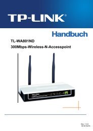
<strong>TL</strong>-<strong>WR841N</strong>/<strong>TL</strong>-<strong>WR841N</strong>D<strong>300Mbps</strong> <strong>Wireless</strong> N <strong>Router</strong>Package ContentsThe following items should be found in your package:‣ <strong>TL</strong>-<strong>WR841N</strong>/<strong>TL</strong>-<strong>WR841N</strong>D <strong>300Mbps</strong> <strong>Wireless</strong> N <strong>Router</strong>‣ DC Power Adapter for <strong>TL</strong>-<strong>WR841N</strong>/<strong>TL</strong>-<strong>WR841N</strong>D <strong>300Mbps</strong> <strong>Wireless</strong> N <strong>Router</strong>‣ Quick Installation Guide‣ Resource CD for <strong>TL</strong>-<strong>WR841N</strong>/<strong>TL</strong>-<strong>WR841N</strong>D <strong>300Mbps</strong> <strong>Wireless</strong> N <strong>Router</strong>, including:• This Guide• Other Helpful Information Note:Make sure that the package contains the above items. If any of the listed items are damaged ormissing, please contact your distributor.- 2 -
<strong>TL</strong>-<strong>WR841N</strong>/<strong>TL</strong>-<strong>WR841N</strong>D<strong>300Mbps</strong> <strong>Wireless</strong> N <strong>Router</strong>Chapter 1. IntroductionThank you for choosing the <strong>TL</strong>-<strong>WR841N</strong>/<strong>TL</strong>-<strong>WR841N</strong>D <strong>300Mbps</strong> <strong>Wireless</strong> N <strong>Router</strong>.1.1 Overview of the <strong>Router</strong>The <strong>TL</strong>-<strong>WR841N</strong>/<strong>TL</strong>-<strong>WR841N</strong>D <strong>300Mbps</strong> <strong>Wireless</strong> N <strong>Router</strong> integrates 4-port Switch, Firewall,NAT-<strong>Router</strong> and <strong>Wireless</strong> AP. Powered by 2x2 MIMO technology, the <strong>300Mbps</strong> <strong>Wireless</strong> N <strong>Router</strong>delivers exceptional range and speed, which can fully meet the need of Small Office/Home Office(SOHO) networks and the users demanding higher networking performance.Incredible SpeedThe <strong>TL</strong>-<strong>WR841N</strong>/<strong>TL</strong>-<strong>WR841N</strong>D <strong>300Mbps</strong> <strong>Wireless</strong> N <strong>Router</strong> provides up to <strong>300Mbps</strong> wirelessconnection with other 802.11n wireless clients. The incredible speed makes it ideal for handlingmultiple data streams at the same time, which ensures your network stable and smooth. Theperformance of this 802.11n wireless <strong>Router</strong> will give you the unexpected networking experience atspeed 650% faster than 802.11g. It is also compatible with all IEEE 802.11g and IEEE 802.11bproducts.Multiple Security ProtectionsWith multiple protection measures, including SSID broadcast control and wireless LAN64/128/152-bit WEP encryption, WiFi protected Access (WPA2- PSK, WPA- PSK), as well asadvanced Firewall protections, the <strong>TL</strong>-<strong>WR841N</strong>/<strong>TL</strong>-<strong>WR841N</strong>D <strong>300Mbps</strong> <strong>Wireless</strong> N <strong>Router</strong>provides complete data privacy.Flexible Access ControlThe <strong>TL</strong>-<strong>WR841N</strong>/<strong>TL</strong>-<strong>WR841N</strong>D <strong>300Mbps</strong> <strong>Wireless</strong> N <strong>Router</strong> provides flexible access control, sothat parents or network administrators can establish restricted access policies for children or staff. Italso supports Virtual Server and DMZ host for Port Triggering, and then the network administratorscan manage and monitor the network in real time with the remote management function.Simple InstallationSince the <strong>Router</strong> is compatible with virtually all the major operating systems, it is very easy tomanage. Quick Setup Wizard is supported and detailed instructions are provided step by step inthis user guide. Before installing the <strong>Router</strong>, please look through this guide to know all the<strong>Router</strong>’s functions.- 3 -
<strong>TL</strong>-<strong>WR841N</strong>/<strong>TL</strong>-<strong>WR841N</strong>D<strong>300Mbps</strong> <strong>Wireless</strong> N <strong>Router</strong>1.2 ConventionsThe <strong>Router</strong> or <strong>TL</strong>-<strong>WR841N</strong>/<strong>TL</strong>-<strong>WR841N</strong>D mentioned in this guide stands for <strong>TL</strong>-<strong>WR841N</strong>/<strong>TL</strong>-<strong>WR841N</strong>D<strong>300Mbps</strong> <strong>Wireless</strong> N <strong>Router</strong> without any explanation. Note:The two devices of <strong>TL</strong>-<strong>WR841N</strong> and <strong>TL</strong>-<strong>WR841N</strong>D are sharing this User Guide. For simplicity, wewill take <strong>TL</strong>-<strong>WR841N</strong>D for example throughout this Guide.The differences between them are:‣ <strong>TL</strong>-<strong>WR841N</strong> <strong>Router</strong> with 2 fixed antennas.‣ <strong>TL</strong>-<strong>WR841N</strong>D <strong>Router</strong> with 2 detachable antennas.1.3 Main Features‣ Complies with IEEE 802.11n to provide a wireless data rate of up to <strong>300Mbps</strong>.‣ One 10/100M Auto-Negotiation RJ45 WAN port, four 10/100M Auto-Negotiation RJ45 LANports, supporting Auto MDI/MDIX.‣ Provides WPA/WPA2, WPA-PSK/WPA2-PSK authentication, TKIP/AES encryption security.‣ Shares data and Internet access for users, supporting Dynamic IP/Static IP/PPPoE Internetaccess.‣ Supports Virtual Server, Special Application and DMZ host.‣ Supports UPnP, Dynamic DNS, Static Routing.‣ Provides Automatic-connection and Scheduled Connection on certain time to the Internet‣ Built-in NAT and DHCP server supporting static IP address distributing.‣ Supports Parental Control and Access Control.‣ Connects Internet on demand and disconnects from the Internet when idle for PPPoE.‣ Provides 64/128/152-bit WEP encryption security and wireless LAN ACL (Access ControlList).‣ Supports Flow Statistics.‣ Supports firmware upgrade and Web management.- 4 -
<strong>TL</strong>-<strong>WR841N</strong>/<strong>TL</strong>-<strong>WR841N</strong>D<strong>300Mbps</strong> <strong>Wireless</strong> N <strong>Router</strong>1.4 Panel Layout1.4.1 The Front PanelFigure 1-1 Front Panel sketchThe <strong>Router</strong>’s LEDs are located on the front panel (View from left to right).Name Status Indication(Power)(System)(WLAN)(WAN),(LAN 1-4)(QSS)OffOnFlashingOn /OffOffFlashingOffPower is off.Power is on.The <strong>Router</strong> is working properly.The <strong>Router</strong> has a system error.The <strong>Wireless</strong> function is disabled.The <strong>Wireless</strong> function is enabled.There is no device linked to the corresponding port.OnThere is a device linked to the corresponding port butthere is no activity.Flashing There is an active device linked to the corresponding port.Slow FlashA wireless device is connecting to the network by QSSfunction. This process will last in the first 2 minutes.OnA wireless device has been successfully added to thenetwork by QSS function.Quick FlashA wireless device failed to be added to the network byQSS function.Table 1-1 The LEDs Description- 5 -
<strong>TL</strong>-<strong>WR841N</strong>/<strong>TL</strong>-<strong>WR841N</strong>D<strong>300Mbps</strong> <strong>Wireless</strong> N <strong>Router</strong> Note:After a device is successfully added to the network by QSS function, the QSS LED will keep on forabout 5 minutes and then turn off.1.4.2 The Rear PanelFigure 1-2 Rear Panel sketchThe following parts are located on the rear panel (View from left to right).‣ ON/OFF: The switch for the power.‣ POWER: The Power socket is where you will connect the power adapter. Please use thepower adapter provided with this <strong>TL</strong>-<strong>WR841N</strong>/<strong>TL</strong>-<strong>WR841N</strong>D <strong>300Mbps</strong> <strong>Wireless</strong> N <strong>Router</strong>.‣ WAN: This WAN port is where you will connect the DSL/cable Modem, or Ethernet.‣ 4,3,2,1 (LAN): These ports (4,3,2,1) connect the <strong>Router</strong> to the local PC(s).‣ RESET:There are two ways to reset to the <strong>Router</strong>'s factory defaults:1) Use the Factory Defaults function on “System Tools → Factory Defaults” page in the<strong>Router</strong>'s Web-based Utility.2) Use the Factory Default RESET button: With the <strong>Router</strong> powered on, use a pin to pressand hold the RESET button (about 5 seconds) until the SYS LED becomes quick-flashfrom slow-flash. And then release the button and wait the <strong>Router</strong> to reboot to its factorydefault settings.‣ <strong>Wireless</strong> antenna: To receive and transmit the wireless data.- 6 -
<strong>TL</strong>-<strong>WR841N</strong>/<strong>TL</strong>-<strong>WR841N</strong>D<strong>300Mbps</strong> <strong>Wireless</strong> N <strong>Router</strong>Chapter 2. Connecting the <strong>Router</strong>2.1 System Requirements‣ Broadband Internet Access Service (DSL/Cable/Ethernet)‣ One DSL/Cable Modem that has an RJ45 connector (which is not necessary if the <strong>Router</strong> isconnected directly to the Ethernet.)‣ PCs with a working Ethernet Adapter and an Ethernet cable with RJ45 connectors‣ TCP/IP protocol on each PC‣ Web browser, such as Microsoft Internet Explorer, Mozilla Firefox or Apple Safari2.2 Installation Environment Requirements‣ Place the <strong>Router</strong> in a well ventilated place far from any heater or heating vent‣ Avoid direct irradiation of any strong light (such as sunlight)‣ Keep at least 2 inches (5 cm) of clear space around the <strong>Router</strong>‣ Operating Temperature: 0 ℃ ~40 ℃ (32 ℉ ~104 ℉ )‣ Operating Humidity: 10%~90%RH, Non-condensing2.3 Connecting the <strong>Router</strong>Before installing the <strong>Router</strong>, make sure your PC is connected to the Internet through thebroadband service successfully. If there is any problem, please contact your ISP. After that, pleaseinstall the <strong>Router</strong> according to the following steps. Don't forget to pull out the power plug and keepyour hands dry.1. Power off your PC, Cable/DSL Modem, and the <strong>Router</strong>.2. Locate an optimum location for the <strong>Router</strong>. The best place is usually at the center of yourwireless network.3. Adjust the direction of the antenna. Normally, upright is a good direction.4. Connect the PC(s) and each Switch/Hub in your LAN to the LAN Ports on the <strong>Router</strong>, shownin Figure 2-1. (If you have the wireless NIC and want to use the wireless function, you canskip this step.)5. Connect the DSL/Cable Modem to the WAN port on the <strong>Router</strong>, shown in Figure 2-1.- 7 -
<strong>TL</strong>-<strong>WR841N</strong>/<strong>TL</strong>-<strong>WR841N</strong>D<strong>300Mbps</strong> <strong>Wireless</strong> N <strong>Router</strong>6. Connect the power adapter to the power socket on the <strong>Router</strong>, and the other end into anelectrical outlet. The <strong>Router</strong> will start to work automatically.7. Power on your PC and Cable/DSL Modem.Figure 2-1 Hardware Installation of the <strong>TL</strong>-<strong>WR841N</strong>D <strong>300Mbps</strong> <strong>Wireless</strong> N <strong>Router</strong>- 8 -
<strong>TL</strong>-<strong>WR841N</strong>/<strong>TL</strong>-<strong>WR841N</strong>D<strong>300Mbps</strong> <strong>Wireless</strong> N <strong>Router</strong>Chapter 3. Quick Installation GuideThis chapter will show you how to configure the basic functions of your <strong>TL</strong>-<strong>WR841N</strong>D <strong>300Mbps</strong><strong>Wireless</strong> N <strong>Router</strong> using Quick Setup Wizard within minutes.3.1 TCP/IP ConfigurationThe default domain name of the <strong>TL</strong>-<strong>WR841N</strong>D <strong>300Mbps</strong> <strong>Wireless</strong> N <strong>Router</strong> ishttp://tplinklogin.net, the default IP address is 192.168.0.1, and the default Subnet Mask is255.255.255.0. These values can be changed as you desire. In this guide, we use all the defaultvalues for description.Connect the local PC to the LAN ports of the <strong>Router</strong>. And then you can configure the IP addressfor your PC in the following two ways.‣ Configure the IP address manually1) Set up the TCP/IP Protocol for your PC. If you need instructions as to how to do this,please refer to Appendix B: "Configuring the PC".2) Configure the network parameters. The IP address is 192.168.0.xxx ("xxx" is any numberfrom 2 to 254), Subnet Mask is 255.255.255.0, and Gateway is 192.168.0.1 (The<strong>Router</strong>'s default IP address)‣ Obtain an IP address automatically1) Set up the TCP/IP Protocol in "Obtain an IP address automatically" mode on your PC.If you need instructions as to how to do this, please refer to Appendix B: "Configuring thePC”.2) Then the built-in DHCP server will assign IP address for the PC.Now, you can run the Ping command in the command prompt to verify the network connectionbetween your PC and the <strong>Router</strong>. The following example is in Windows 2000 OS.Open a command prompt, and type ping 192.168.0.1, and then press Enter.‣ If the result displayed is similar to the Figure 3-1, it means the connection between your PCand the <strong>Router</strong> has been established well.- 9 -
<strong>TL</strong>-<strong>WR841N</strong>/<strong>TL</strong>-<strong>WR841N</strong>D<strong>300Mbps</strong> <strong>Wireless</strong> N <strong>Router</strong>Figure 3-1 Success result of Ping command‣ If the result displayed is similar to the Figure 3-2, it means the connection between your PCand the <strong>Router</strong> is failed.Figure 3-2 Failure result of Ping commandPlease check the connection following these steps:1. Is the connection between your PC and the <strong>Router</strong> correct? Note:The 1/2/3/4 LEDs of LAN ports which you link to on the <strong>Router</strong> and LEDs on your PC's adapter- 10 -
<strong>TL</strong>-<strong>WR841N</strong>/<strong>TL</strong>-<strong>WR841N</strong>D<strong>300Mbps</strong> <strong>Wireless</strong> N <strong>Router</strong>should be lit.2. Is the TCP/IP configuration for your PC correct? Note:If the <strong>Router</strong>'s IP address is 192.168.0.1, your PC's IP address must be within the range of192.168.0.2 ~ 192.168.0.254.3. Is the default LAN IP of the <strong>Router</strong> correct? Note:If the LAN IP of the modem connected with your router is 192.168.0.x, the default LAN IP of the<strong>Router</strong> will automatically switch from 192.168.0.1 to 192.168.1.1 to avoid IP conflict. Therefore, inorder to verify the network connection between your PC and the <strong>Router</strong>, you can open acommand prompt, and type ping 192.168.1.1, and then press Enter.3.2 Quick Installation GuideWith a Web-based utility, it is easy to configure and manage the <strong>TL</strong>-<strong>WR841N</strong>D <strong>300Mbps</strong> <strong>Wireless</strong>N <strong>Router</strong>. The Web-based utility can be used on any Windows, Macintosh or UNIX OS with a Webbrowser, such as Microsoft Internet Explorer, Mozilla Firefox or Apple Safari.1. To access the configuration utility, open a web-browser and type in the default addresshttp://tplinklogin.net in the address field of the browser.Figure 3-3 Log in the <strong>Router</strong>After a moment, a login window will appear, similar to the Figure 3-4. Enter admin for theUser Name and Password, both in lower case letters. Then click the OK button or press theEnter key.- 11 -
<strong>TL</strong>-<strong>WR841N</strong>/<strong>TL</strong>-<strong>WR841N</strong>D<strong>300Mbps</strong> <strong>Wireless</strong> N <strong>Router</strong>Figure 3-4 Login Windows Note:If the above screen does not pop-up, it means that your Web-browser has been set to a proxy.Go to Tools menu>Internet Options>Connections>LAN Settings, in the screen that appears,cancel the Using Proxy checkbox, and click OK to finish it.1. After successfully log in, you can click the Quick Setup menu to quickly configure your<strong>Router</strong>.Figure 3-5 Quick Setup2. Click Next, and then WAN Connection Type page will appear, shown in Figure 3-6.- 12 -
<strong>TL</strong>-<strong>WR841N</strong>/<strong>TL</strong>-<strong>WR841N</strong>D<strong>300Mbps</strong> <strong>Wireless</strong> N <strong>Router</strong>Figure 3-6 WAN Connection TypeThe <strong>Router</strong> provides Auto-Detect function and supports three popular ways PPPoE,Dynamic IP and Static IP to connect to the Internet. It’s recommended that you make use ofthe Auto-Detect function. If you are sure of what kind of connection type your ISP provides,you can select the very type and click Next to go on configuring.3. If you select Auto-Detect, the <strong>Router</strong> will automatically detect the connection type your ISPprovides. Make sure the cable is securely plugged into the WAN port before detection. Theappropriate configuration page will be displayed when an active Internet service issuccessfully detected by the <strong>Router</strong>.1) If the connection type detected is PPPoE, the next screen will appear as shown in Figure3-7.Figure 3-7 Quick Setup - PPPoE‣ User Name/Password - Enter the User Name and Password provided by your ISP.These fields are case sensitive. If you have difficulty with this process, please contact yourISP.‣ Confirm Password - Re-enter the password provided by your ISP to ensure thePassword you entered is correct. If the Password is different from the Confirm Password,the screen will appear as shown below. Click OK, and re-enter the Password andConfirm Password.- 13 -
<strong>TL</strong>-<strong>WR841N</strong>/<strong>TL</strong>-<strong>WR841N</strong>D<strong>300Mbps</strong> <strong>Wireless</strong> N <strong>Router</strong>2) If the connection type detected is Dynamic IP, the next screen will appear as shown inFigure 3-9. Then you can go on with the wireless configuration.‣ If you are visiting the <strong>Router</strong> from the main computer, please select Yes, and thenclick Clone MAC Address.Figure 3-8 Quick Setup – MAC Clone‣ If you are visiting the <strong>Router</strong> from another computer, rather than the main computer,please select No, and then enter the main computer’s MAC in the field WAN MACAddress.Figure 3-9 Quick Setup – MAC Clone3) If the connection type detected is Static IP, the next screen will appear as shown in Figure3-8.- 14 -
<strong>TL</strong>-<strong>WR841N</strong>/<strong>TL</strong>-<strong>WR841N</strong>D<strong>300Mbps</strong> <strong>Wireless</strong> N <strong>Router</strong>Figure 3-8 Quick Setup - Static IP‣ IP Address - This is the WAN IP address as seen by external users on the Internet(including your ISP). Enter the IP address into the field.‣ Subnet Mask - The Subnet Mask is used for the WAN IP address, it is usually255.255.255.0.‣ Default Gateway - Enter the gateway IP address into the box if required.‣ Primary DNS - Enter the DNS Server IP address into the box if required.‣ Secondary DNS - If your ISP provides another DNS server, enter it into this field.4. Click Next to continue, the <strong>Wireless</strong> settings page will appear as shown in Figure 3-9.Figure 3-9 Quick Setup – <strong>Wireless</strong>- 15 -
<strong>TL</strong>-<strong>WR841N</strong>/<strong>TL</strong>-<strong>WR841N</strong>D<strong>300Mbps</strong> <strong>Wireless</strong> N <strong>Router</strong>‣ <strong>Wireless</strong> Radio - Enable or disable the wireless radio choosing from the drop-down list.‣ <strong>Wireless</strong> Network Name - Enter a value of up to 32 characters. The same name ofSSID (Service Set Identification) must be assigned to all wireless devices in yournetwork. Considering your wireless network security, the default SSID is set to be<strong>TP</strong>-LINK_XXXXXX (XXXXXX indicates the last unique six numbers of each <strong>Router</strong>’sMAC address). This value is case-sensitive. For example, TEST is NOT the same astest.‣ Region - Select your region from the drop-down list. This field specifies the regionwhere the wireless function of the <strong>Router</strong> can be used. It may be illegal to use thewireless function of the <strong>Router</strong> in a region other than one of those specified in this field.If your country or region is not listed, please contact your local government agency forassistance. Note:Limited by local law regulations, version for North America does not have regionselection option.‣ Channel - This field determines which operating frequency will be used. The defaultchannel is set to Auto, so the AP will choose the best channel automatically. It is notnecessary to change the wireless channel unless you notice interference problems withanother nearby access point.‣ Mode - This field determines the wireless mode which the <strong>Router</strong> works on.‣ Channel Width - Select any channel width from the drop-down list. The default settingis automatic, which can adjust the channel width for your clients automatically.‣ Max Tx Rate - You can limit the maximum transmission rate of the <strong>Router</strong> through thisfield.‣ Disable Security - The wireless security function can be enabled or disabled. Ifdisabled, the wireless stations will be able to connect the <strong>Router</strong> without encryption. It isrecommended strongly that you choose one of following options to enable security.‣ WPA-PSK/WPA2-PSK - Select WPA based on pre-shared passphrase.• PSK Password - You can enter ASCII or Hexadecimal characters.For ASCII, the key can be made up of any numbers 0 to 9 and any letters A to Z, thelength should be between 8 and 63 characters.For Hexadecimal, the key can be made up of any numbers 0 to 9 and letters A to F,the length should be between 8 and 64 characters.Please also note the key is case sensitive, this means that upper and lower casekeys will affect the outcome. It would also be a good idea to write down the key andall related wireless security settings.- 16 -
<strong>TL</strong>-<strong>WR841N</strong>/<strong>TL</strong>-<strong>WR841N</strong>D<strong>300Mbps</strong> <strong>Wireless</strong> N <strong>Router</strong>‣ No Change - If you chose this option, wireless security configuration will not change!These settings are only for basic wireless parameters. For advanced settings, please refer to4.6 <strong>Wireless</strong>.5. Click the Next button. You will then see the Finish page.If you don’t make any changes on the <strong>Wireless</strong> page, you will see the Finish page as shownin Figure 3-10. Click the Finish button to finish the Quick Setup.Figure 3-10 Quick Setup - FinishIf there are something changed on the <strong>Wireless</strong> page, you will see the Finish page as shownin Figure 3-11. Click the Reboot button to make your wireless configuration to take effect andfinish the Quick Setup.Figure 3-11 Quick Setup – Finish- 17 -
<strong>TL</strong>-<strong>WR841N</strong>/<strong>TL</strong>-<strong>WR841N</strong>D<strong>300Mbps</strong> <strong>Wireless</strong> N <strong>Router</strong>Chapter 4. Configuring the <strong>Router</strong>This chapter will show each Web page's key functions and the configuration way.4.1 LoginAfter your successful login, you will see the fifteen main menus on the left of the Web-based utility.On the right, there are the corresponding explanations and instructions.The detailed explanations for each Web page’s key function are listed below.4.2 StatusThe Status page provides the current status information about the <strong>Router</strong>. All information isread-only.- 18 -
<strong>TL</strong>-<strong>WR841N</strong>/<strong>TL</strong>-<strong>WR841N</strong>D<strong>300Mbps</strong> <strong>Wireless</strong> N <strong>Router</strong>Figure 4-1 <strong>Router</strong> Status4.3 Quick SetupPlease refer to 3.2 Quick Installation Guide.4.4 QSSThis section will guide you to add a new wireless device to an existing network quickly by QSS(Quick Secure Setup) function.- 19 -
<strong>TL</strong>-<strong>WR841N</strong>/<strong>TL</strong>-<strong>WR841N</strong>D<strong>300Mbps</strong> <strong>Wireless</strong> N <strong>Router</strong>a). Choose menu “QSS”, and you will see the next screen (shown in Figure 4-2 ).Figure 4-2 QSS‣ QSS Status - Enable or disable the QSS function here.‣ Current PIN - The current value of the <strong>Router</strong>'s PIN is displayed here. The default PIN of the<strong>Router</strong> can be found in the label or User Guide.‣ Restore PIN - Restore the PIN of the <strong>Router</strong> to its default.‣ Gen New PIN - Click this button, and then you can get a new random value for the <strong>Router</strong>'sPIN. You can ensure the network security by generating a new PIN.‣ Add device - You can add a new device to the existing network manually by clicking thisbutton.b).To add a new device:If the wireless adapter supports Wi-Fi Protected Setup (WPS), you can establish a wirelessconnection between wireless adapter and <strong>Router</strong> using either Push Button Configuration (PBC)method or PIN method. Note:To build a successful connection by QSS, you should also do the corresponding configuration ofthe new device for QSS function meanwhile.For the configuration of the new device, here takes the <strong>Wireless</strong> Adapter of our company forexample.I. By PBCIf the wireless adapter supports Wi-Fi Protected Setup and the Push Button Configuration (PBC)method, you can add it to the network by PBC with the following two methods.Method One:Step 1: Press the QSS button on the front panel of the <strong>Router</strong>.- 20 -
<strong>TL</strong>-<strong>WR841N</strong>/<strong>TL</strong>-<strong>WR841N</strong>D<strong>300Mbps</strong> <strong>Wireless</strong> N <strong>Router</strong>Step 2: Press and hold the QSS button of the adapter directly for 2 or 3 seconds.Step 3: Wait for a while until the next screen appears. Click Finish to complete the QSSconfiguration.The QSS Configuration Screen of <strong>Wireless</strong> AdapterMethod Two:Step 1: Press the QSS button on the front panel of the <strong>Router</strong>.Step 2: For the configuration of the wireless adapter, please choose “Push the button on myaccess point” in the configuration utility of the QSS as below, and click Next.- 21 -
<strong>TL</strong>-<strong>WR841N</strong>/<strong>TL</strong>-<strong>WR841N</strong>D<strong>300Mbps</strong> <strong>Wireless</strong> N <strong>Router</strong>The QSS Configuration Screen of <strong>Wireless</strong> AdapterStep 3: Wait for a while until the next screen appears. Click Finish to complete the QSSconfiguration.The QSS Configuration Screen of <strong>Wireless</strong> AdapterMethod Three:Step 1: Keep the default QSS Status as Enabled and click the Add device button in Figure 4-2,then the following screen will appear.- 22 -
<strong>TL</strong>-<strong>WR841N</strong>/<strong>TL</strong>-<strong>WR841N</strong>D<strong>300Mbps</strong> <strong>Wireless</strong> N <strong>Router</strong>Figure 4-3 Add A New DeviceStep 2: Choose “Press the button of the new device in two minutes” and click Connect.Step 3: For the configuration of the wireless adapter, please choose “Push the button on myaccess point” in the configuration utility of the QSS as below, and click Next.The QSS Configuration Screen of <strong>Wireless</strong> AdapterStep 4: Wait for a while until the next screen appears. Click Finish to complete the QSSconfiguration.- 23 -
<strong>TL</strong>-<strong>WR841N</strong>/<strong>TL</strong>-<strong>WR841N</strong>D<strong>300Mbps</strong> <strong>Wireless</strong> N <strong>Router</strong>The QSS Configuration Screen of <strong>Wireless</strong> AdapterII. By PINIf the new device supports Wi-Fi Protected Setup and the PIN method, you can add it to thenetwork by PIN with the following two methods.Method One: Enter the PIN into my <strong>Router</strong>Step 1: Keep the default QSS Status as Enabled and click the Add device button in Figure 4-2,then the following screen will appear.Step 2: Choose “Enter the new device's PIN” and enter the PIN code of the wireless adapter inthe field after PIN as shown in the figure above. Then click Connect. Note:The PIN code of the adapter is always displayed on the QSS configuration screen.Step 3: For the configuration of the wireless adapter, please choose “Enter a PIN into myaccess point or a registrar” in the configuration utility of the QSS as below, and clickNext.- 24 -
<strong>TL</strong>-<strong>WR841N</strong>/<strong>TL</strong>-<strong>WR841N</strong>D<strong>300Mbps</strong> <strong>Wireless</strong> N <strong>Router</strong>The QSS Configuration Screen of <strong>Wireless</strong> Adapter Note:In this example, the default PIN code of this adapter is 16952898 as the above figure shown.Method Two: Enter the PIN from my <strong>Router</strong>Step 1: Get the Current PIN code of the <strong>Router</strong> in Figure 4-2 (each <strong>Router</strong> has its unique PINcode. Here takes the PIN code 12345670 of this <strong>Router</strong> for example).Step 2: For the configuration of the wireless adapter, please choose “Enter a PIN from myaccess point” in the configuration utility of the QSS as below, and enter the PIN code ofthe <strong>Router</strong> into the field after “Access Point PIN”. Then click Next.- 25 -
<strong>TL</strong>-<strong>WR841N</strong>/<strong>TL</strong>-<strong>WR841N</strong>D<strong>300Mbps</strong> <strong>Wireless</strong> N <strong>Router</strong>The QSS Configuration Screen of <strong>Wireless</strong> Adapter Note:The default PIN code of the <strong>Router</strong> can be found in its label or the QSS configuration screen asFigure 4-2.c). You will see the following screen when the new device successfully connected to thenetwork. Note:1) The QSS LED on the <strong>Router</strong> will light green for five minutes if the device has beensuccessfully added to the network.2) The QSS function cannot be configured if the <strong>Wireless</strong> Function of the <strong>Router</strong> is disabled.Please make sure the <strong>Wireless</strong> Function is enabled before configuring the QSS.- 26 -
<strong>TL</strong>-<strong>WR841N</strong>/<strong>TL</strong>-<strong>WR841N</strong>D<strong>300Mbps</strong> <strong>Wireless</strong> N <strong>Router</strong>4.5 NetworkFigure 4-4 the Network menuThere are three submenus under the Network menu (shown in Figure 4-4): LAN, WAN and MACClone. Click any of them, and you will be able to configure the corresponding function.4.5.1 WANChoose menu “Network → WAN”, you can configure the IP parameters of the WAN on thescreen below.1. If your ISP provides the DHCP service, please choose Dynamic IP type, and the <strong>Router</strong> willautomatically get IP parameters from your ISP. You can see the page as follows (Figure4-5):Figure 4-5 WAN – Dynamic IPThis page displays the WAN IP parameters assigned dynamically by your ISP, including IPaddress, Subnet Mask, Default Gateway, etc. Click the Renew button to renew the IP- 27 -
<strong>TL</strong>-<strong>WR841N</strong>/<strong>TL</strong>-<strong>WR841N</strong>D<strong>300Mbps</strong> <strong>Wireless</strong> N <strong>Router</strong>parameters from your ISP. Click the Release button to release the IP parameters.‣ MTU Size - The normal MTU (Maximum Transmission Unit) value for most Ethernet networksis 1500 Bytes. It is not recommended that you change the default MTU Size unless requiredby your ISP.‣ Use These DNS Servers - If your ISP gives you one or two DNS addresses, select UseThese DNS Servers and enter the primary and secondary addresses into the correct fields.Otherwise, the DNS servers will be assigned dynamically from your ISP. Note:If you find error when you go to a website after entering the DNS addresses, it is likely thatyour DNS servers are set up improperly. You should contact your ISP to get DNS serveraddresses.‣ Host Name - This option specifies the Host Name of the <strong>Router</strong>.‣ Get IP with Unicast DHCP - A few ISPs' DHCP servers do not support the broadcastapplications. If you cannot get the IP Address normally, you can choose this option. (It israrely required.)Click the Save button to save your settings.2. If your ISP provides a static or fixed IP Address, Subnet Mask, Gateway and DNS setting,select Static IP. The Static IP settings page will appear, shown in Figure 4-6.Figure 4-6 WAN - Static IP- 28 -
<strong>TL</strong>-<strong>WR841N</strong>/<strong>TL</strong>-<strong>WR841N</strong>D<strong>300Mbps</strong> <strong>Wireless</strong> N <strong>Router</strong>‣ IP Address - Enter the IP address in dotted-decimal notation provided by your ISP.‣ Subnet Mask - Enter the subnet Mask in dotted-decimal notation provided by your ISP,usually is 255.255.255.0.‣ Default Gateway - (Optional) Enter the gateway IP address in dotted-decimal notationprovided by your ISP.‣ MTU Size - The normal MTU (Maximum Transmission Unit) value for most Ethernet networksis 1500 Bytes. It is not recommended that you change the default MTU Size unless requiredby your ISP.‣ Primary/Secondary DNS - (Optional) Enter one or two DNS addresses in dotted-decimalnotation provided by your ISP.Click the Save button to save your settings.- 29 -
<strong>TL</strong>-<strong>WR841N</strong>/<strong>TL</strong>-<strong>WR841N</strong>D<strong>300Mbps</strong> <strong>Wireless</strong> N <strong>Router</strong>3. If your ISP provides a PPPoE connection, select PPPoE/Russia PPPoE option. And youshould enter the following parameters (Figure 4-7):Figure 4-7 WAN - PPPoE‣ User Name/Password - Enter the User Name and Password provided by your ISP. Thesefields are case-sensitive.‣ Secondary Connection - It’s available only for PPPoE Connection. If your ISP provides anextra Connection type such as Dynamic/Static IP to connect to a local area network, then youcan check the radio button of Dynamic/Static IP to activate this secondary connection.• Disabled - The Secondary Connection is disabled by default, so there is PPPoEconnection only. This is recommended.• Dynamic IP - You can check this radio button to use Dynamic IP as the secondaryconnection to connect to the local area network provided by ISP.• Static IP - You can check this radio button to use Static IP as the secondary connectionto connect to the local area network provided by ISP.‣ Connect on Demand - In this mode, the Internet connection can be terminated automaticallyafter a specified inactivity period (Max Idle Time) and be re-established when you attempt toaccess the Internet again. If you want your Internet connection keeps active all the time,- 30 -
<strong>TL</strong>-<strong>WR841N</strong>/<strong>TL</strong>-<strong>WR841N</strong>D<strong>300Mbps</strong> <strong>Wireless</strong> N <strong>Router</strong>please enter “0” in the Max Idle Time field. Otherwise, enter the number of minutes you wantto have elapsed before your Internet access disconnects.‣ Connect Automatically - The connection can be re-established automatically when it wasdown.‣ Time-based Connecting - The connection will only be established in the period from thestart time to the end time (both are in HH:MM format). Note:Only when you have configured the system time on “System Tools → Time” page, will theTime-based Connecting function can take effect.‣ Connect Manually - You can click the Connect/Disconnect button to connect/disconnectimmediately. This mode also supports the Max Idle Time function as Connect on Demandmode. The Internet connection can be disconnected automatically after a specified inactivityperiod and re-established when you attempt to access the Internet again.Click the Connect button to connect immediately. Click the Disconnect button to disconnectimmediately.Caution: Sometimes the connection cannot be terminated although you specify a time to Max IdleTime because some applications are visiting the Internet continually in the background.If you want to do some advanced configurations, please click the Advanced button, and the pageshown in Figure 4-8 will then appear:Figure 4-8 PPPoE Advanced Settings- 31 -
<strong>TL</strong>-<strong>WR841N</strong>/<strong>TL</strong>-<strong>WR841N</strong>D<strong>300Mbps</strong> <strong>Wireless</strong> N <strong>Router</strong>‣ MTU Size - The default MTU size is “1480” bytes, which is usually fine. It is notrecommended that you change the default MTU Size unless required by your ISP.‣ Service Name/AC Name - The service name and AC (Access Concentrator) name shouldnot be configured unless you are sure it is necessary for your ISP. In most cases, leavingthese fields blank will work.‣ ISP Specified IP Address - If your ISP does not automatically assign IP addresses to the<strong>Router</strong> during login, please click “Use IP address specified by ISP” check box and enter theIP address provided by your ISP in dotted-decimal notation.‣ Detect Online Interval - The <strong>Router</strong> will detect Access Concentrator online at every interval.The default value is “0”. You can input the value between “0” and “120”. The value “0” meansno detect.‣ Primary DNS/Secondary DNS - If your ISP does not automatically assign DNS addresses tothe <strong>Router</strong> during login, please click “Use the following DNS servers” check box and enterthe IP address in dotted-decimal notation of your ISP’s primary DNS server. If a secondaryDNS server address is available, enter it as well.Click the Save button to save your settings.4. If your ISP provides BigPond Cable (or Heart Beat Signal) connection, please selectBigPond Cable. And you should enter the following parameters (Figure 4-9):Figure 4-9- 32 -
<strong>TL</strong>-<strong>WR841N</strong>/<strong>TL</strong>-<strong>WR841N</strong>D<strong>300Mbps</strong> <strong>Wireless</strong> N <strong>Router</strong>‣ User Name/Password - Enter the User Name and Password provided by your ISP. Thesefields are case-sensitive.‣ Auth Server - Enter the authenticating server IP address or host name.‣ Auth Domain - Type in the domain suffix server name based on your location.e.g.NSW / ACT - nsw.bigpond.net.auVIC / TAS / WA / SA / NT - vic.bigpond.net.auQLD - qld.bigpond.net.au‣ MTU Size - The normal MTU (Maximum Transmission Unit) value for most Ethernet networksis 1500 Bytes. It is not recommended that you change the default MTU Size unless requiredby your ISP.‣ Connect on Demand - In this mode, the Internet connection can be terminated automaticallyafter a specified inactivity period (Max Idle Time) and be re-established when you attempt toaccess the Internet again. If you want your Internet connection keeps active all the time,please enter “0” in the Max Idle Time field. Otherwise, enter the number of minutes you wantto have elapsed before your Internet access disconnects.‣ Connect Automatically - The connection can be re-established automatically when it wasdown.‣ Connect Manually - You can click the Connect/Disconnect button to connect/disconnectimmediately. This mode also supports the Max Idle Time function as Connect on Demandmode. The Internet connection can be disconnected automatically after a specified inactivityperiod and re-established when you attempt to access the Internet again.Click the Connect button to connect immediately. Click the Disconnect button to disconnectimmediately.Caution: Sometimes the connection cannot be terminated although you specify a time to Max IdleTime because some applications are visiting the Internet continually in the background.Click the Save button to save your settings.5. If your ISP provides L2<strong>TP</strong> connection, please select L2<strong>TP</strong>/Russia L2<strong>TP</strong> option. And youshould enter the following parameters (Figure 4-10):- 33 -
<strong>TL</strong>-<strong>WR841N</strong>/<strong>TL</strong>-<strong>WR841N</strong>D<strong>300Mbps</strong> <strong>Wireless</strong> N <strong>Router</strong>Figure 4-10‣ User Name/Password - Enter the User Name and Password provided by your ISP. Thesefields are case-sensitive.‣ Dynamic IP/ Static IP - Choose either as you are given by your ISP. Click the Connectbutton to connect immediately. Click the Disconnect button to disconnect immediately.‣ Connect on Demand - You can configure the <strong>Router</strong> to disconnect from your Internetconnection after a specified period of inactivity (Max Idle Time). If your Internet connectionhas been terminated due to inactivity, Connect on Demand enables the <strong>Router</strong> toautomatically re-establish your connection as soon as you attempt to access the Internetagain. If you wish to activate Connect on Demand, check the radio button. If you want yourInternet connection to remain active at all times, enter 0 in the Max Idle Time field. Otherwise,enter the number of minutes you want to have elapsed before your Internet connectionterminates.- 34 -
<strong>TL</strong>-<strong>WR841N</strong>/<strong>TL</strong>-<strong>WR841N</strong>D<strong>300Mbps</strong> <strong>Wireless</strong> N <strong>Router</strong>‣ Connect Automatically - Connect automatically after the <strong>Router</strong> is disconnected. To use thisoption, check the radio button.‣ Connect Manually - You can configure the <strong>Router</strong> to make it connect or disconnect manually.After a specified period of inactivity (Max Idle Time), the <strong>Router</strong> will disconnect from yourInternet connection, and you will not be able to re-establish your connection automatically assoon as you attempt to access the Internet again. To use this option, check the radio button. Ifyou want your Internet connection to remain active at all times, enter "0" in the Max Idle Timefield. Otherwise, enter the number of minutes that you wish to have the Internet connectinglast unless a new link is requested.Caution: Sometimes the connection cannot be disconnected although you specify a time to MaxIdle Time, because some applications are visiting the Internet continually in the background.Click the Save button to save your settings.6. If your ISP provides PP<strong>TP</strong> connection, please select PP<strong>TP</strong>/Russia PP<strong>TP</strong> option. And youshould enter the following parameters (Figure 4-11):- 35 -
<strong>TL</strong>-<strong>WR841N</strong>/<strong>TL</strong>-<strong>WR841N</strong>D<strong>300Mbps</strong> <strong>Wireless</strong> N <strong>Router</strong>Figure 4-11 PP<strong>TP</strong> Settings‣ User Name/Password - Enter the User Name and Password provided by your ISP. Thesefields are case-sensitive.‣ Dynamic IP/ Static IP - Choose either as you are given by your ISP and enter the ISP’s IPaddress or the domain name.If you choose static IP and enter the domain name, you should also enter the DNS assignedby your ISP. And click the Save button.Click the Connect button to connect immediately. Click the Disconnect button to disconnectimmediately.‣ Connect on Demand - You can configure the <strong>Router</strong> to disconnect from your Internetconnection after a specified period of inactivity (Max Idle Time). If your Internet connectionhas been terminated due to inactivity, Connect on Demand enables the <strong>Router</strong> to- 36 -
<strong>TL</strong>-<strong>WR841N</strong>/<strong>TL</strong>-<strong>WR841N</strong>D<strong>300Mbps</strong> <strong>Wireless</strong> N <strong>Router</strong>automatically re-establish your connection as soon as you attempt to access the Internetagain. If you wish to activate Connect on Demand, check the radio button. If you want yourInternet connection to remain active at all times, enter “0” in the Max Idle Time field.Otherwise, enter the number of minutes you want to have elapsed before your Internetconnection terminates.‣ Connect Automatically - Connect automatically after the <strong>Router</strong> is disconnected. To use thisoption, check the radio button.‣ Connect Manually - You can configure the <strong>Router</strong> to make it connect or disconnect manually.After a specified period of inactivity (Max Idle Time), the <strong>Router</strong> will disconnect from yourInternet connection, and you will not be able to re-establish your connection automatically assoon as you attempt to access the Internet again. To use this option, click the radio button. Ifyou want your Internet connection to remain active at all times, enter "0" in the Max Idle Timefield. Otherwise, enter the number in minutes that you wish to have the Internet connectinglast unless a new link is requested.Caution: Sometimes the connection cannot be disconnected although you specify a time to MaxIdle Time because some applications are visiting the Internet continually in the background.Click the Save button to save your settings. Note:If you don't know how to choose the appropriate connection type, click the Detect button to allowthe <strong>Router</strong> to automatically search your Internet connection for servers and protocols. Theconnection type will be reported when an active Internet service is successfully detected by the<strong>Router</strong>. This report is for your reference only. To make sure the connection type your ISP provides,please refer to the ISP. The various types of Internet connections that the <strong>Router</strong> can detect areas follows:• PPPoE - Connections which use PPPoE that requires a user name and password.• Dynamic IP - Connections which use dynamic IP address assignment.• Static IP - Connections which use static IP address assignment.The <strong>Router</strong> can not detect PP<strong>TP</strong>/L2<strong>TP</strong>/BigPond connections with your ISP. If your ISP uses oneof these protocols, then you must configure your connection manually.4.5.2 LANChoose menu “Network → LAN”, you can configure the IP parameters of the LAN on the screenas below.- 37 -
<strong>TL</strong>-<strong>WR841N</strong>/<strong>TL</strong>-<strong>WR841N</strong>D<strong>300Mbps</strong> <strong>Wireless</strong> N <strong>Router</strong>Figure 4-12 LAN‣ MAC Address - The physical address of the <strong>Router</strong>, as seen from the LAN. The value can'tbe changed.‣ IP Address - Enter the IP address of your <strong>Router</strong> or reset it in dotted-decimal notation(factory default: 192.168.0.1).‣ Subnet Mask - An address code that determines the size of the network. Normally use255.255.255.0 as the subnet mask. Note:1) If you change the IP Address of LAN, you must use the new IP Address to log in the <strong>Router</strong>.2) If the new LAN IP Address you set is not in the same subnet, the IP Address pool of the DHCPserver will change accordingly at the same time,while the Virtual Server and DMZ Host willnot take effect until they are re-configured.4.5.3 MAC CloneChoose menu “Network → MAC Clone”, you can configure the MAC address of the WAN onthe screen below, Figure 4-13:Figure 4-13 MAC Address CloneSome ISPs require that you register the MAC Address of your adapter. Changes are rarelyneeded here.- 38 -
<strong>TL</strong>-<strong>WR841N</strong>/<strong>TL</strong>-<strong>WR841N</strong>D<strong>300Mbps</strong> <strong>Wireless</strong> N <strong>Router</strong>‣ WAN MAC Address - This field displays the current MAC address of the WAN port. If yourISP requires you to register the MAC address, please enter the correct MAC address intothis field in XX-XX-XX-XX-XX-XX format (X is any hexadecimal digit).‣ Your PC's MAC Address - This field displays the MAC address of the PC that is managingthe <strong>Router</strong>. If the MAC address is required, you can click the Clone MAC Address Tobutton and this MAC address will fill in the WAN MAC Address field.Click Restore Factory MAC to restore the MAC address of WAN port to the factory defaultvalue.Click the Save button to save your settings. Note:Only the PC on your LAN can use the MAC Address Clone function.4.6 <strong>Wireless</strong>Figure 4-14 <strong>Wireless</strong> menuThere are five submenus under the <strong>Wireless</strong> menu (shown in Figure 4-14): <strong>Wireless</strong> Settings,<strong>Wireless</strong> Security, <strong>Wireless</strong> MAC Filtering, <strong>Wireless</strong> Advanced and <strong>Wireless</strong> Statistics. Clickany of them, and you will be able to configure the corresponding function.4.6.1 <strong>Wireless</strong> SettingsChoose menu “<strong>Wireless</strong> → <strong>Wireless</strong> Settings”, you can configure the basic settings for thewireless network on this page.- 39 -
<strong>TL</strong>-<strong>WR841N</strong>/<strong>TL</strong>-<strong>WR841N</strong>D<strong>300Mbps</strong> <strong>Wireless</strong> N <strong>Router</strong>Figure 4-15 <strong>Wireless</strong> Settings‣ <strong>Wireless</strong> Network Name - Enter a value of up to 32 characters. The same name of SSID(Service Set Identification) must be assigned to all wireless devices in your network.Considering your wireless network security, the default SSID is set to be <strong>TP</strong>-LINK_XXXXXX(XXXXXX indicates the last unique six numbers of each <strong>Router</strong>’s MAC address). This valueis case-sensitive. For example, TEST is NOT the same as test.‣ Region - Select your region from the drop-down list. This field specifies the region where thewireless function of the <strong>Router</strong> can be used. It may be illegal to use the wireless function ofthe <strong>Router</strong> in a region other than one of those specified in this field. If your country or regionis not listed, please contact your local government agency for assistance.When you select your local region from the drop-down list, click the Save button, then theNote Dialog appears. Click OK.Note Dialog Note:Limited by local law regulations, version for North America does not have region selectionoption.‣ Channel - This field determines which operating frequency will be used. The default channelis set to Auto, so the AP will choose the best channel automatically. It is not necessary to- 40 -
<strong>TL</strong>-<strong>WR841N</strong>/<strong>TL</strong>-<strong>WR841N</strong>D<strong>300Mbps</strong> <strong>Wireless</strong> N <strong>Router</strong>change the wireless channel unless you notice interference problems with another nearbyaccess point.‣ Mode - Select the desired mode. The default setting is 11bgn mixed.11b only - Select if all of your wireless clients are 802.11b.11g only - Select if all of your wireless clients are 802.11g.11n only- Select only if all of your wireless clients are 802.11n.11bg mixed - Select if you are using both 802.11b and 802.11g wireless clients.11bgn mixed - Select if you are using a mix of 802.11b, 11g, and 11n wireless clients.Select the desired wireless mode. When 802.11g mode is selected, only 802.11g wirelessstations can connect to the <strong>Router</strong>. When 802.11n mode is selected, only 802.11n wirelessstations can connect to the AP. It is strongly recommended that you set the Mode to802.11b&g&n, and all of 802.11b, 802.11g, and 802.11n wireless stations can connect tothe <strong>Router</strong>.‣ Channel width - Select the channel width from the drop-down list. The default setting isautomatic, which can adjust the channel width for your clients automatically. Note:If 11b only, 11g only, or 11bg mixed is selected in the Mode field, the Channel Widthselecting field will turn grey and the value will become 20M, which is unable to be changed.‣ Max Tx Rate - You can limit the maximum tx rate of the <strong>Router</strong> through this field.‣ Enable <strong>Wireless</strong> <strong>Router</strong> Radio - The wireless radio of this <strong>Router</strong> can be enabled ordisabled to allow wireless stations access.‣ Enable SSID Broadcast - When wireless clients survey the local area for wireless networksto associate with, they will detect the SSID broadcast by the <strong>Router</strong>. If you select the EnableSSID Broadcast checkbox, the <strong>Wireless</strong> <strong>Router</strong> will broadcast its name (SSID) on the air.‣ Enable WDS - Check this box to enable WDS. With this function, the <strong>Router</strong> can bridge twoor more Wlans. If this checkbox is selected, you will have to set the following parameters asshown in Figure 4-16. Make sure the following settings are correct.Figure 4-16- 41 -
<strong>TL</strong>-<strong>WR841N</strong>/<strong>TL</strong>-<strong>WR841N</strong>D<strong>300Mbps</strong> <strong>Wireless</strong> N <strong>Router</strong>‣ SSID(to be bridged) - The SSID of the AP your <strong>Router</strong> is going to connect to as a client.You can also use the search function to select the SSID to join.‣ BSSID(to be bridged) - The BSSID of the AP your <strong>Router</strong> is going to connect to as aclient. You can also use the search function to select the BSSID to join.‣ Survey - Click this button, you can search the AP which runs in the current channel.‣ Key type - This option should be chosen according to the AP's security configuration. Itis recommended that the security type is the same as your AP's security type‣ WEP Index - This option should be chosen if the key type is WEP(ASCII) orWEP(HEX).It indicates the index of the WEP key.‣ Auth Type - This option should be chosen if the key type is WEP(ASCII) orWEP(HEX).It indicates the authorization type of the Root AP.‣ Password - If the AP your <strong>Router</strong> is going to connect needs password, you need to fillthe password in this blank.4.6.2 <strong>Wireless</strong> SecurityChoose menu “<strong>Wireless</strong> → <strong>Wireless</strong> Security”, you can configure the security settings of yourwireless network.There are five wireless security modes supported by the <strong>Router</strong>: WEP (Wired Equivalent Privacy),WPA (Wi-Fi Protected Access), WPA2 (Wi-Fi Protected Access 2), WPA-PSK (Pre-Shared Key),WPA2-PSK (Pre-Shared Key).- 42 -
<strong>TL</strong>-<strong>WR841N</strong>/<strong>TL</strong>-<strong>WR841N</strong>D<strong>300Mbps</strong> <strong>Wireless</strong> N <strong>Router</strong>Figure 4-17 <strong>Wireless</strong> Security‣ Disable Security - If you do not want to use wireless security, check this radio button. But it’sstrongly recommended to choose one of the following modes to enable security.‣ WEP - It is based on the IEEE 802.11 standard. If you check this radio button, you will find anotice in red as show in Figure 4-18.Figure 4-18• Type - you can choose the type for the WEP security on the drop-down list. The defaultsetting is Automatic, which can select Shared Key or Open System authentication type- 43 -
<strong>TL</strong>-<strong>WR841N</strong>/<strong>TL</strong>-<strong>WR841N</strong>D<strong>300Mbps</strong> <strong>Wireless</strong> N <strong>Router</strong>automatically based on the wireless station's capability and request.• WEP Key Format - Hexadecimal and ASCII formats are provided here. Hexadecimalformat stands for any combination of hexadecimal digits (0-9, a-f, A-F) in the specifiedlength. ASCII format stands for any combination of keyboard characters in the specifiedlength.• WEP Key - Select which of the four keys will be used and enter the matching WEP key thatyou create. Make sure these values are identical on all wireless stations in your network.• Key Type - You can select the WEP key length (64-bit, or 128-bit, or 152-bit.) forencryption. "Disabled" means this WEP key entry is invalid.64-bit - You can enter 10 hexadecimal digits (any combination of 0-9, a-f, A-F, zero key isnot promoted) or 5 ASCII characters.128-bit - You can enter 26 hexadecimal digits (any combination of 0-9, a-f, A-F, zero key isnot promoted) or 13 ASCII characters.152-bit - You can enter 32 hexadecimal digits (any combination of 0-9, a-f, A-F, zero key isnot promoted) or 16 ASCII characters. Note:If you do not set the key, the wireless security function is still disabled even if you haveselected Shared Key as Authentication Type.‣ WPA /WPA2 – Enterprise - It’s based on Radius Server.• Version - you can choose the version of the WPA security on the drop-down list. Thedefault setting is Automatic, which can select WPA (Wi-Fi Protected Access) or WPA2(WPA version 2) automatically based on the wireless station's capability and request.• Encryption - You can select either Automatic, or TKIP or AES. Note:If you check the WPA /WPA2 – Enterprise radio button and choose TKIP encryption, youwill find a notice in red as shown in Figure 4-19.Figure 4-19• Radius Server IP - Enter the IP address of the Radius server.- 44 -
<strong>TL</strong>-<strong>WR841N</strong>/<strong>TL</strong>-<strong>WR841N</strong>D<strong>300Mbps</strong> <strong>Wireless</strong> N <strong>Router</strong>• Radius Port - Enter the port number of the Radius server.• Radius Password - Enter the password for the Radius server.• Group Key Update Period - Specify the group key update interval in seconds. The valueshould be 30 or above. Enter 0 to disable the update.‣ WPA-PSK/WPA2-PSK – Personal (Recommended) - It’s the WPA/WPA2 authenticationtype based on pre-shared passphrase.• Version - you can choose the version of the WPA-PSK security on the drop-down list. Thedefault setting is Automatic, which can select WPA-PSK (Pre-shared key of WPA) orWPA2-PSK (Pre-shared key of WPA) automatically based on the wireless station'scapability and request.• Encryption - When WPA-PSK or WPA is set as the Authentication Type, you can selecteither Automatic, or TKIP or AES as Encryption. Note:If you check the WPA-PSK/WPA2-PSK – Personal (Recommended) radio button andchoose TKIP encryption, you will find a notice in red as shown in Figure 4-20.Figure 4-20• PSK Passphrase - You can enter ASCII characters between 8 and 63 characters or 8 to64 Hexadecimal characters.• Group Key Update Period - Specify the group key update interval in seconds. The valueshould be 30 or above. Enter 0 to disable the update.Be sure to click the Save button to save your settings on this page.4.6.3 <strong>Wireless</strong> MAC FilteringChoose menu “<strong>Wireless</strong> → MAC Filtering”, you can control the wireless access by configuringthe <strong>Wireless</strong> MAC Filtering function, shown in Figure 4-21.- 45 -
<strong>TL</strong>-<strong>WR841N</strong>/<strong>TL</strong>-<strong>WR841N</strong>D<strong>300Mbps</strong> <strong>Wireless</strong> N <strong>Router</strong>Figure 4-21 <strong>Wireless</strong> MAC FilteringTo filter wireless users by MAC Address, click Enable. The default setting is Disable.‣ MAC Address - The wireless station's MAC address that you want to filter.‣ Status - The status of this entry, either Enabled or Disabled.‣ Description - A simple description of the wireless station.To Add a <strong>Wireless</strong> MAC Address filtering entry, click the Add New… button. The "Add or Modify<strong>Wireless</strong> MAC Address Filtering entry" page will appear, shown in Figure 4-22:Figure 4-22 Add or Modify <strong>Wireless</strong> MAC Address Filtering entryTo add or modify a MAC Address Filtering entry, follow these instructions:1. Enter the appropriate MAC Address into the MAC Address field. The format of the MACAddress is XX-XX-XX-XX-XX-XX (X is any hexadecimal digit). For example:00-0A-EB-B0-00-0B.2. Give a simple description for the wireless station in the Description field. For example:<strong>Wireless</strong> station A.- 46 -
<strong>TL</strong>-<strong>WR841N</strong>/<strong>TL</strong>-<strong>WR841N</strong>D<strong>300Mbps</strong> <strong>Wireless</strong> N <strong>Router</strong>3. Select Enabled or Disabled for this entry on the Status drop-down list.4. Click the Save button to save this entry.To modify or delete an existing entry:1. Click the Modify in the entry you want to modify. If you want to delete the entry, click theDelete.2. Modify the information.3. Click the Save button.Click the Enable All button to make all entries enabledClick the Disabled All button to make all entries disabled.Click the Delete All button to delete all entries.Click the Next button to go to the next page.Click the Previous button to return to the previous page.For example: If you desire that the wireless station A with MAC address 00-0A-EB-B0-00-0B andthe wireless station B with MAC address 00-0A-EB-00-07-5F are able to access the <strong>Router</strong>, but allthe other wireless stations cannot access the <strong>Router</strong>, you can configure the <strong>Wireless</strong> MACAddress Filtering list by following these steps:1. Click the Enable button to enable this function.2. Select the radio button “Deny the stations not specified by any enabled entries in the list toaccess” for Filtering Rules.3. Delete all or disable all entries if there are any entries already.4. Click the Add New... button.1) Enter the MAC address 00-0A-EB-B0-00-0B/00-0A-EB-00-07-5F in the MAC Address field.2) Enter wireless station A/B in the Description field.3) Select Enabled in the Status drop-down list.4) Click the Save button.5) Click the Back button.The filtering rules that configured should be similar to the following list:- 47 -
<strong>TL</strong>-<strong>WR841N</strong>/<strong>TL</strong>-<strong>WR841N</strong>D<strong>300Mbps</strong> <strong>Wireless</strong> N <strong>Router</strong>4.6.4 <strong>Wireless</strong> AdvancedChoose menu “<strong>Wireless</strong> → <strong>Wireless</strong> Advanced”, you can configure the advanced settings ofyour wireless network.Figure 4-23 <strong>Wireless</strong> Advanced‣ Transmit Power - Here you can specify the transmit power of <strong>Router</strong>. You can select High,Middle or Low which you would like. High is the default setting and is recommended.‣ Beacon Interval - Enter a value between 20-1000 milliseconds for Beacon Interval here.The beacons are the packets sent by the <strong>Router</strong> to synchronize a wireless network. BeaconInterval value determines the time interval of the beacons. The default value is 100.‣ RTS Threshold - Here you can specify the RTS (Request to Send) Threshold. If the packetis larger than the specified RTS Threshold size, the <strong>Router</strong> will send RTS frames to aparticular receiving station and negotiate the sending of a data frame. The default value is2346.‣ Fragmentation Threshold - This value is the maximum size determining whether packetswill be fragmented. Setting the Fragmentation Threshold too low may result in poor networkperformance because of excessive packets. 2346 is the default setting and isrecommended.‣ DTIM Interval - This value determines the interval of the Delivery Traffic Indication Message(DTIM). A DTIM field is a countdown field informing clients of the next window for listening tobroadcast and multicast messages. When the <strong>Router</strong> has buffered broadcast or multicastmessages for associated clients, it sends the next DTIM with a DTIM Interval value. You canspecify the value between 1-255 Beacon Intervals. The default value is 1, which indicatesthe DTIM Interval is the same as Beacon Interval.- 48 -
<strong>TL</strong>-<strong>WR841N</strong>/<strong>TL</strong>-<strong>WR841N</strong>D<strong>300Mbps</strong> <strong>Wireless</strong> N <strong>Router</strong>‣ Enable WMM - WMM function can guarantee the packets with high-priority messages beingtransmitted preferentially. It is strongly recommended.‣ Enable Short GI - This function is recommended for it will increase the data capacity byreducing the guard interval time.‣ Enabled AP Isolation - This function can isolate wireless stations on your network fromeach other. <strong>Wireless</strong> devices will be able to communicate with the <strong>Router</strong> but not with eachother. To use this function, check this box. AP Isolation is disabled by default. Note:If you are not familiar with the setting items in this page, it's strongly recommended to keepthe provided default values; otherwise it may result in lower wireless network performance.4.6.5 <strong>Wireless</strong> StatisticsChoose menu “<strong>Wireless</strong> → <strong>Wireless</strong> Statistics”, you can see the MAC Address, Current Status,Received Packets and Sent Packets for each connected wireless station.Figure 4-24 <strong>Wireless</strong> Statistics‣ MAC Address - The connected wireless station's MAC address‣ Current Status - The connected wireless station's running status, one of STA-AUTH/STA-ASSOC/ STA-JOINED/ WPA/ WPA-PSK/ WPA2/ WPA2-PSK/ AP-UP/ AP-DOWN/ Disconnected‣ Received Packets - Packets received by the station‣ Sent Packets - Packets sent by the stationYou cannot change any of the values on this page. To update this page and to show the currentconnected wireless stations, click on the Refresh button.If the numbers of connected wireless stations go beyond one page, click the Next button to go tothe next page and click the Previous button to return the previous page. Note:This page will be refreshed automatically every 5 seconds.- 49 -
<strong>TL</strong>-<strong>WR841N</strong>/<strong>TL</strong>-<strong>WR841N</strong>D<strong>300Mbps</strong> <strong>Wireless</strong> N <strong>Router</strong>4.7 DHCPFigure 4-25 The DHCP menuThere are three submenus under the DHCP menu (shown in Figure 4-25), DHCP Settings,DHCP Clients List and Address Reservation. Click any of them, and you will be able toconfigure the corresponding function.4.7.1 DHCP SettingsChoose menu “DHCP → DHCP Settings”, you can configure the DHCP Server on the page asshown in Figure 4-26.The <strong>Router</strong> is set up by default as a DHCP (Dynamic Host ConfigurationProtocol) server, which provides the TCP/IP configuration for all the PC(s) that are connected tothe <strong>Router</strong> on the LAN.Figure 4-26 DHCP Settings‣ DHCP Server - Enable or Disable the DHCP server. If you disable the Server, you musthave another DHCP server within your network or else you must configure the computermanually.‣ Start IP Address - Specify an IP address for the DHCP Server to start with when assigningIP addresses. 192.168.0.100 is the default start address.‣ End IP Address - Specify an IP address for the DHCP Server to end with when assigning IPaddresses. 192.168.0.199 is the default end address.- 50 -
<strong>TL</strong>-<strong>WR841N</strong>/<strong>TL</strong>-<strong>WR841N</strong>D<strong>300Mbps</strong> <strong>Wireless</strong> N <strong>Router</strong>‣ Address Lease Time - The Address Lease Time is the amount of time a network user willbe allowed connection to the <strong>Router</strong> with their current dynamic IP Address. Enter theamount of time in minutes and the user will be "leased" this dynamic IP Address. After thetime is up, the user will be automatically assigned a new dynamic IP address. The range ofthe time is 1 ~ 2880 minutes. The default value is 120 minutes.‣ Default Gateway - (Optional.) It is suggested to input the IP address of the LAN port of the<strong>Router</strong>. The default value is 192.168.0.1.‣ Default Domain - (Optional.) Input the domain name of your network.‣ Primary DNS - (Optional.) Input the DNS IP address provided by your ISP or consult yourISP.‣ Secondary DNS - (Optional.) Input the IP address of another DNS server if your ISPprovides two DNS servers. Note:To use the DHCP server function of the <strong>Router</strong>, you must configure all computers on the LAN as"Obtain an IP Address automatically".4.7.2 DHCP Clients ListChoose menu “DHCP → DHCP Clients List”, you can view the information about the clientsattached to the <strong>Router</strong> in the screen as shown in Figure 4-27.Figure 4-27 DHCP Clients List‣ Client Name - The name of the DHCP client‣ MAC Address - The MAC address of the DHCP client‣ Assigned IP - The IP address that the <strong>Router</strong> has allocated to the DHCP client‣ Lease Time - The time of the DHCP client leased. After the dynamic IP address has expired,a new dynamic IP address will be automatically assigned to the user.You cannot change any of the values on this page. To update this page and to show the currentattached devices, click the Refresh button.- 51 -
<strong>TL</strong>-<strong>WR841N</strong>/<strong>TL</strong>-<strong>WR841N</strong>D<strong>300Mbps</strong> <strong>Wireless</strong> N <strong>Router</strong>4.7.3 Address ReservationChoose menu “DHCP → Address Reservation”, you can view and add a reserved address forclients via the next screen (shown in Figure 4-28).When you specify a reserved IP address for aPC on the LAN, that PC will always receive the same IP address each time when it accesses theDHCP server. Reserved IP addresses should be assigned to the servers that require permanentIP settings.Figure 4-28 Address Reservation‣ MAC Address - The MAC address of the PC for which you want to reserve an IP address.‣ Reserved IP Address - The IP address reserved for the PC by the <strong>Router</strong>.‣ Status - The status of this entry, either Enabled or Disabled.To Reserve an IP address:1. Click the Add New… button. Then Figure 4-29 will pop-up.2. Enter the MAC address (in XX-XX-XX-XX-XX-XX format.) and IP address (in dotted-decimalnotation) of the computer for which you want to reserve an IP address.3. Click the Save button.To modify or delete an existing entry:Figure 4-29 Add or Modify an Address Reservation Entry- 52 -
<strong>TL</strong>-<strong>WR841N</strong>/<strong>TL</strong>-<strong>WR841N</strong>D<strong>300Mbps</strong> <strong>Wireless</strong> N <strong>Router</strong>1. Click the Modify in the entry you want to modify. If you want to delete the entry, click theDelete.2. Modify the information.3. Click the Save button.Click the Enable/Disabled All button to make all entries enabled/disabledClick the Delete All button to delete all entries.Click the Next button to go to the next page and Click the Previous button to return the previouspage.4.8 ForwardingFigure 4-30 The Forwarding menuThere are four submenus under the Forwarding menu (shown in Figure 4-30), Virtual Servers,Port Triggering, DMZ and UPnP. Click any of them, and you will be able to configure thecorresponding function.4.8.1 Virtual ServersChoose menu “Forwarding → Virtual Servers”, you can view and add virtual servers in thescreen as shown in Figure 4-31. Virtual servers can be used for setting up public services onyour LAN, such as DNS, Email and F<strong>TP</strong>. A virtual server is defined as a service port, and allrequests from the Internet to this service port will be redirected to the computer specified by theserver IP. Any PC that was used for a virtual server must have a static or reserved IP Addressbecause its IP Address may be changed when using the DHCP function.Figure 4-31 Virtual Servers‣ Service Port - The numbers of External Ports. You can type a service port or a range ofservice ports (in XXX – YYY format, XXX is the start port number, YYY is the end portnumber).- 53 -
<strong>TL</strong>-<strong>WR841N</strong>/<strong>TL</strong>-<strong>WR841N</strong>D<strong>300Mbps</strong> <strong>Wireless</strong> N <strong>Router</strong>‣ IP Address - The IP Address of the PC providing the service application.‣ Protocol - The protocol used for this application, either TCP, UDP, or All (all protocolssupported by the <strong>Router</strong>).‣ Status - The status of this entry, either Enabled or Disabled.To set up a virtual server entry:1. Click the Add New… button, the next screen will pop-up as shown in Figure 4-32.2. Select the service port you want to use from the Common Service Port list. If the CommonService Port list does not have the service that you want to use, type the service portnumber or service port range in the Service Port box.3. Type the IP Address of the computer in the IP Address box.4. Select the protocol used for this application, either TCP, UDP, or All.5. Select the Enable to enable the virtual server.6. Click the Save button.Figure 4-32 Add or Modify a Virtual Server Entry Note:If your computer or server has more than one type of available service, please select anotherservice, and enter the same IP Address for that computer or server.To modify or delete an existing entry:1. Click the Modify in the entry you want to modify. If you want to delete the entry, click theDelete.2. Modify the information.3. Click the Save button.Click the Enable/Disabled All button to make all entries enabled/disabled.Click the Delete All button to delete all entries.- 54 -
<strong>TL</strong>-<strong>WR841N</strong>/<strong>TL</strong>-<strong>WR841N</strong>D<strong>300Mbps</strong> <strong>Wireless</strong> N <strong>Router</strong>Click the Next button to go to the next page and click the Previous button to return the previouspage. Note:If you set the service port of the virtual server as 80, you must set the Web management port on“Security → Remote Management” page to be any other value except 80 such as 8080.Otherwise there will be a conflict to disable the virtual server.4.8.2 Port TriggeringChoose menu “Forwarding → Port Triggering”, you can view and add port triggering in the screenas shown in Figure 4-33. Some applications require multiple connections, like Internet games, videoconferencing, Internet calling and so on. These applications cannot work with a pure NAT <strong>Router</strong>.Port Triggering is used for some of these applications that can work with an NAT <strong>Router</strong>.Figure 4-33 Port TriggeringOnce the <strong>Router</strong> is configured, the operation is as follows:1. A local host makes an outgoing connection using a destination port number defined in theTrigger Port field.2. The <strong>Router</strong> records this connection, opens the incoming port or ports associated with thisentry in the Port Triggering table, and associates them with the local host.3. When necessary, the external host will be able to connect to the local host using one of theports defined in the Incoming Ports field.‣ Trigger Port - The port for outgoing traffic. An outgoing connection using this port will triggerthis rule.‣ Trigger Protocol - The protocol used for Trigger Ports, either TCP, UDP, or All (allprotocols supported by the <strong>Router</strong>).‣ Incoming Ports Range - The port or port range used by the remote system when itresponds to the outgoing request. A response using one of these ports will be forwarded tothe PC that triggered this rule. You can input at most 5 groups of ports (or port sections).Every group of ports must be set apart with ",". For example, 2000-2038, 2050-2051, 2085,3010-3030.‣ Incoming Protocol - The protocol used for Incoming Ports Range, either TCP or UDP, or- 55 -
<strong>TL</strong>-<strong>WR841N</strong>/<strong>TL</strong>-<strong>WR841N</strong>D<strong>300Mbps</strong> <strong>Wireless</strong> N <strong>Router</strong>ALL (all protocols supported by the <strong>Router</strong>).‣ Status - The status of this entry, either Enabled or Disabled.To add a new rule, follow the steps below.1. Click the Add New… button, the next screen will pop-up as shown in Figure 4-34.2. Select a common application from the Common Applications drop-down list, then theTrigger Port field and the Incoming Ports field will be automatically filled. If the CommonApplications do not have the application you need, enter the Trigger Port and theIncoming Ports manually.3. Select the protocol used for Trigger Port from the Trigger Protocol drop-down list, eitherTCP, UDP, or All.4. Select the protocol used for Incoming Ports from the Incoming Protocol drop-down list,either TCP or UDP, or All.5. Select Enable in Status field.6. Click the Save button to save the new rule.Figure 4-34 Add or Modify a Port Triggering EntryTo modify or delete an existing entry:1. Click the Modify in the entry you want to modify. If you want to delete the entry, click theDelete.2. Modify the information.3. Click the Save button.Click the Enable All button to make all entries enabledClick the Disabled All button to make all entries disabled.Click the Delete All button to delete all entries- 56 -
<strong>TL</strong>-<strong>WR841N</strong>/<strong>TL</strong>-<strong>WR841N</strong>D<strong>300Mbps</strong> <strong>Wireless</strong> N <strong>Router</strong> Note:1. When the trigger connection is released, the corresponding opening ports will be closed.2. Each rule is allowed to be used only by one host on LAN synchronously. The triggerconnection of other hosts on LAN will be refused.3. Incoming Port Range cannot overlap each other.4.8.3 DMZChoose menu “Forwarding → DMZ”, you can view and configure DMZ host in the screen asshown in Figure 4-35. The DMZ host feature allows one local host to be exposed to the Internetfor a special-purpose service such as Internet gaming or videoconferencing. DMZ host forwardsall the ports at the same time. Any PC whose port is being forwarded must have its DHCP clientfunction disabled and should have a new static IP Address assigned to it because its IP Addressmay be changed when using the DHCP function.Figure 4-35 DMZTo assign a computer or server to be a DMZ server:1. Check the Enable radio button2. Enter the IP Address of a local host in the DMZ Host IP Address field3. Click the Save button. Note:After you set the DMZ host, the firewall related to the host will not work.4.8.4 UPnPChoose menu “Forwarding → UPnP”, you can view the information about UPnP (Universal Plugand Play) in the screen as shown in Figure 4-36. The UPnP feature allows the devices, such asInternet computers, to access the local host resources or devices as needed. UPnP devices canbe automatically discovered by the UPnP service application on the LAN.- 57 -
<strong>TL</strong>-<strong>WR841N</strong>/<strong>TL</strong>-<strong>WR841N</strong>D<strong>300Mbps</strong> <strong>Wireless</strong> N <strong>Router</strong>Figure 4-36 UPnP‣ Current UPnP Status - UPnP can be enabled or disabled by clicking the Enable or Disablebutton.‣ Current UPnP Settings List - This table displays the current UPnP information.• App Description - The description provided by the application in the UPnP request.• External Port - The external port the <strong>Router</strong> opens for the application.• Protocol - The type of protocol the <strong>Router</strong> opens for the application.• Internal Port - The Internal port the <strong>Router</strong> opens for local host.• IP Address - The IP address of the UPnP device that is currently accessing the <strong>Router</strong>.• Status - The status of the port is displayed here. “Enabled” means that the port is stillactive. Otherwise, the port is inactive.Click Refresh to update the Current UPnP Settings List.4.9 SecurityFigure 4-37 The Security menuThere are four submenus under the Security menu as shown in Figure 4-37: Basic Security,Advanced Security, Local Management and Remote Management. Click any of them, and youwill be able to configure the corresponding function.- 58 -
<strong>TL</strong>-<strong>WR841N</strong>/<strong>TL</strong>-<strong>WR841N</strong>D<strong>300Mbps</strong> <strong>Wireless</strong> N <strong>Router</strong>4.9.1 Basic SecurityChoose menu “Security → Basic Security”, you can configure the basic security in the screenas shown in Figure 4-38.Figure 4-38 Basic Security‣ Firewall - A firewall protects your network from the outside world. Here you can enable ordisable the <strong>Router</strong>’s firewall.• SPI Firewall - SPI (Stateful Packet Inspection, also known as dynamic packet filtering)helps to prevent cyber attacks by tracking more state per session. It validates that thetraffic passing through the session conforms to the protocol. SPI Firewall is enabled byfactory default. If you want all the computers on the LAN exposed to the outside world,you can disable it.‣ VPN - VPN Passthrough must be enabled if you want to allow VPN tunnels using IPSec,PP<strong>TP</strong>, or L2<strong>TP</strong> protocols to pass through the <strong>Router</strong>’s firewall.• PP<strong>TP</strong> Passthrough - Point-to-Point Tunneling Protocol (PP<strong>TP</strong>) allows the Point-to-PointProtocol (PPP) to be tunneled through an IP network. To allow PP<strong>TP</strong> tunnels to passthrough the <strong>Router</strong>, keep the default, Enabled.• L2<strong>TP</strong> Passthrough - Layer 2 Tunneling Protocol (L2<strong>TP</strong>) is the method used to enablePoint-to-Point sessions via the Internet on the Layer 2 level. To allow L2<strong>TP</strong> tunnels topass through the <strong>Router</strong>, keep the default, Enabled.- 59 -
<strong>TL</strong>-<strong>WR841N</strong>/<strong>TL</strong>-<strong>WR841N</strong>D<strong>300Mbps</strong> <strong>Wireless</strong> N <strong>Router</strong>• IPSec Passthrough - Internet Protocol Security (IPSec) is a suite of protocols forensuring private, secure communications over Internet Protocol (IP) networks, throughthe use of cryptographic security services. To allow IPSec tunnels to pass through the<strong>Router</strong>, keep the default, Enabled.‣ ALG - It is recommended to enable Application Layer Gateway (ALG) because ALG allowscustomized Network Address Translation (NAT) traversal filters to be plugged into thegateway to support address and port translation for certain application layer "control/data"protocols such as F<strong>TP</strong>, TF<strong>TP</strong>, H323 etc.• F<strong>TP</strong> ALG - To allow F<strong>TP</strong> clients and servers to transfer data across NAT, keep thedefault Enable.• TF<strong>TP</strong> ALG - To allow TF<strong>TP</strong> clients and servers to transfer data across NAT, keep thedefault Enable.• H323 ALG - To allow Microsoft NetMeeting clients to communicate across NAT, keepthe default Enable.Click the Save button to save your settings.4.9.2 Advanced SecurityChoose menu “Security → Advanced Security”, you can protect the <strong>Router</strong> from beingattacked by TCP-SYN Flood, UDP Flood and ICMP-Flood in the screen as shown in Figure 4-39.Figure 4-39 Advanced Security- 60 -
<strong>TL</strong>-<strong>WR841N</strong>/<strong>TL</strong>-<strong>WR841N</strong>D<strong>300Mbps</strong> <strong>Wireless</strong> N <strong>Router</strong>‣ Packets Statistics Interval (5~60) - The default value is 10. Select a value between 5 and60 seconds from the drop-down list. The Packets Statistics Interval value indicates the timesection of the packets statistics. The result of the statistics is used for analysis by SYN Flood,UDP Flood and ICMP-Flood.‣ DoS Protection - Denial of Service protection. Check the Enable or Disable button toenable or disable the DoS protection function. Only when it is enabled, will the flood filters beenabled. Note:Dos Protection will take effect only when the Traffic Statistics in “System Tool → TrafficStatistics” is enabled.‣ Enable ICMP-FLOOD Attack Filtering - Enable or Disable the ICMP-FLOOD AttackFiltering.‣ ICMP-FLOOD Packets Threshold (5~3600) - The default value is 50. Enter a valuebetween 5 ~ 3600. When the current ICMP-FLOOD Packets number is beyond the set value,the <strong>Router</strong> will startup the blocking function immediately.‣ Enable UDP-FLOOD Filtering - Enable or Disable the UDP-FLOOD Filtering.‣ UDP-FLOOD Packets Threshold (5~3600) - The default value is 500. Enter a valuebetween 5 ~ 3600. When the current UPD-FLOOD Packets number is beyond the set value,the <strong>Router</strong> will startup the blocking function immediately.‣ Enable TCP-SYN-FLOOD Attack Filtering - Enable or Disable the TCP-SYN-FLOODAttack Filtering.‣ TCP-SYN-FLOOD Packets Threshold (5~3600) - The default value is 50. Enter a valuebetween 5 ~ 3600. When the current TCP-SYN-FLOOD Packets numbers is beyond the setvalue, the <strong>Router</strong> will startup the blocking function immediately.‣ Ignore Ping Packet From WAN Port - Enable or Disable Ignore Ping Packet From WANPort. The default setting is disabled. If enabled, the ping packet from the Internet cannotaccess the <strong>Router</strong>.‣ Forbid Ping Packet From LAN Port - Enable or Disable Forbid Ping Packet From LAN Port.The default setting is disabled. If enabled, the ping packet from LAN cannot access the<strong>Router</strong>. This function can be used to defend against some viruses.Click the Save button to save the settings.Click the Blocked DoS Host List button to display the DoS host table by blocking.4.9.3 Local ManagementChoose menu “Security → Local Management”, you can configure the management rule in the- 61 -
<strong>TL</strong>-<strong>WR841N</strong>/<strong>TL</strong>-<strong>WR841N</strong>D<strong>300Mbps</strong> <strong>Wireless</strong> N <strong>Router</strong>screen as shown in Figure 4-40. The management feature allows you to deny computers in LANfrom accessing the <strong>Router</strong>.Figure 4-40 Local ManagementBy default, the radio button “All the PCs on the LAN are allowed to access the <strong>Router</strong>'sWeb-Based Utility” is checked. If you want to allow PCs with specific MAC Addresses to accessthe Setup page of the <strong>Router</strong>'s Web-Based Utility locally from inside the network, check the radiobutton “Only the PCs listed can browse the built-in web pages to perform Administratortasks”, and then enter each MAC Address in a separate field. The format for the MAC Address isXX-XX-XX-XX-XX-XX (X is any hexadecimal digit). Only the PCs with MAC address listed canuse the password to browse the built-in web pages to perform Administrator tasks while all theothers will be blocked.After click the Add button, your PC's MAC Address will be placed in the list above.Click the Save button to save your settings. Note:If your PC is blocked but you want to access the <strong>Router</strong> again, use a pin to press and hold theReset Button (hole) on the back panel for about 5 seconds to reset the <strong>Router</strong>’s factory defaultson the <strong>Router</strong>’s Web-Based Utility.4.9.4 Remote ManagementChoose menu “Security → Remote Management”, you can configure the Remote Managementfunction in the screen as shown in Figure 4-41. This feature allows you to manage your <strong>Router</strong>from a remote location via the Internet.- 62 -
<strong>TL</strong>-<strong>WR841N</strong>/<strong>TL</strong>-<strong>WR841N</strong>D<strong>300Mbps</strong> <strong>Wireless</strong> N <strong>Router</strong>Figure 4-41 Remote Management‣ Web Management Port - Web browser access normally uses the standard HT<strong>TP</strong> serviceport 80. This <strong>Router</strong>'s default remote management web port number is 80. For greatersecurity, you can change the remote management web port to a custom port by entering thatnumber in the box provided. Choose a number between 1 and 65534 but do not use thenumber of any common service port.‣ Remote Management IP Address - This is the current address you will use when accessingyour <strong>Router</strong> from the Internet. This function is disabled when the IP address is set to thedefault value of 0.0.0.0. To enable this function change 0.0.0.0 to a valid IP address. If set to255.255.255.255, then all the hosts can access the <strong>Router</strong> from internet. Note:3) To access the <strong>Router</strong>, you should type your <strong>Router</strong>'s WAN IP address into your browser'saddress (in IE) or Location (in Navigator) box, followed by a colon and the custom portnumber. For example, if your <strong>Router</strong>'s WAN address is 202.96.12.8, and the port numberused is 8080, please enter http://202.96.12.8:8080 in your browser. Later, you may beasked for the <strong>Router</strong>'s password. After successfully entering the username and password,you will be able to access the <strong>Router</strong>'s web-based utility.4) Be sure to change the <strong>Router</strong>'s default password to a very secure password.4.10 Parental ControlChoose menu “Parental Control”, and you can configure the parental control in the screen asshown in Figure 4-42. The Parental Control function can be used to control the internet activitiesof the child, limit the child to access certain websites and restrict the time of surfing.- 63 -
<strong>TL</strong>-<strong>WR841N</strong>/<strong>TL</strong>-<strong>WR841N</strong>D<strong>300Mbps</strong> <strong>Wireless</strong> N <strong>Router</strong>Figure 4-42 Parental Control Settings‣ Parental Control - Check Enable if you want this function to take effect, otherwise checkDisable.‣ MAC Address of Parental PC - In this field, enter the MAC address of the controlling PC, oryou can make use of the Copy To Above button below.‣ MAC Address of Your PC - This field displays the MAC address of the PC that is managingthis <strong>Router</strong>. If the MAC Address of your adapter is registered, you can click the Copy ToAbove button to fill this address to the MAC Address of Parental PC field above.‣ Website Description - Description of the allowed website for the PC controlled.‣ Schedule - The time period allowed for the PC controlled to access the Internet. For detailedinformation, please go to “Access Control → Schedule”.‣ Modify - Here you can edit or delete an existing entry.To add a new entry, please follow the steps below.1. Click the Add New… button and the next screen will pop-up as shown in Figure 4-43.2. Enter the MAC address of the PC (e.g. 00-11-22-33-44-AA) you’d like to control in the MACAddress of Child PC field. Or you can choose the MAC address from the All Address inCurrent LAN drop-down list.3. Give a description (e.g. Allow Google) for the website allowed to be accessed in the WebsiteDescription field.4. Enter the allowed domain name of the website, either the full name or the keywords (e.g.google) in the Allowed Domain Name field. Any domain name with keywords in it(www.google.com, www.google.com.cn) will be allowed.5. Select from the Effective Time drop-down list the schedule (e.g. Schedule_1) you want theentry to take effect. If there are not suitable schedules for you, click the Schedule in redbelow to go to the Advance Schedule Settings page and create the schedule you need.- 64 -
<strong>TL</strong>-<strong>WR841N</strong>/<strong>TL</strong>-<strong>WR841N</strong>D<strong>300Mbps</strong> <strong>Wireless</strong> N <strong>Router</strong>6. In the Status field, you can select Enabled or Disabled to enable or disable your entry.7. Click the Save button.Click the Enable All button to enable all the rules in the list.Click the Disable All button to disable all the rules in the list.Click the Delete All button to delete all the entries in the table.Click the Next button to go to the next page, or click the Previous button return to the previouspage.Figure 4-43 Add or Modify Parental Control EntryFor example: If you desire that the child PC with MAC address 00-11-22-33-44-AA can accesswww.google.com on Saturday only while the parent PC with MAC address 00-11-22-33-44-BB iswithout any restriction, you should follow the settings below.1. Click “Parental Control” menu on the left to enter the Parental Control Settings page.Check Enable and enter the MAC address 00-11-22-33-44-BB in the MAC Address ofParental PC field.2. Click “Access Control → Schedule” on the left to enter the Schedule Settings page.Click Add New... button to create a new schedule with Schedule Description isSchedule_1, Day is Sat and Time is all day-24 hours.- 65 -
<strong>TL</strong>-<strong>WR841N</strong>/<strong>TL</strong>-<strong>WR841N</strong>D<strong>300Mbps</strong> <strong>Wireless</strong> N <strong>Router</strong>3. Click “Parental Control” menu on the left to go back to the Add or Modify ParentalControl Entry page:• Click Add New... button.• Enter 00-11-22-33-44-AA in the MAC Address of Child PC field.• Enter “Allow Google” in the Website Description field.• Enter “www.google.com” in the Allowed Domain Name field.• Select “Schedule_1” you create just now from the Effective Time drop-down list.• In Status field, select Enable.4. Click Save to complete the settings.Then you will go back to the Parental Control Settings page and see the following list, asshown in Figure 4-44.Figure 4-44 Parental Control Settings4.11 Access ControlFigure 4-45 Access ControlThere are four submenus under the Access Control menu as shown in Figure 4-45: Rule, Host,Target and Schedule. Click any of them, and you will be able to configure the correspondingfunction.4.11.1 RuleChoose menu “Access Control → Rule”, you can view and set Access Control rules in thescreen as shown in Figure 4-46.- 66 -
<strong>TL</strong>-<strong>WR841N</strong>/<strong>TL</strong>-<strong>WR841N</strong>D<strong>300Mbps</strong> <strong>Wireless</strong> N <strong>Router</strong>Figure 4-46 Access Control Rule Management‣ Enable Internet Access Control - Select the check box to enable the Internet AccessControl function, so the Default Filter Policy can take effect.‣ Rule Name - Here displays the name of the rule and this name is unique.‣ Host - Here displays the host selected in the corresponding rule.‣ Target - Here displays the target selected in the corresponding rule.‣ Schedule - Here displays the schedule selected in the corresponding rule.‣ Action - Here displays the action the <strong>Router</strong> takes to deal with the packets. It could be Allowor Deny. Allow means that the <strong>Router</strong> permits the packets to go through the <strong>Router</strong>. Denymeans that the <strong>Router</strong> rejects the packets to go through the <strong>Router</strong>.‣ Status - This field displays the status of the rule. Enabled means the rule will take effect,Disabled means the rule will not take effect.‣ Modify - Here you can edit or delete an existing rule.To add a new rule, please follow the steps below.1. Click the Add New… button and the next screen will pop-up as shown in Figure 4-47.2. Give a name (e.g. Rule_1) for the rule in the Rule Name field.3. Select a host from the Host drop-down list or choose “Click Here To Add New Host List”.4. Select a target from the Target drop-sown list or choose “Click Here To Add New TargetList”.- 67 -
<strong>TL</strong>-<strong>WR841N</strong>/<strong>TL</strong>-<strong>WR841N</strong>D<strong>300Mbps</strong> <strong>Wireless</strong> N <strong>Router</strong>5. Select a schedule from the Schedule drop-down list or choose “Click Here To Add NewSchedule”.6. In the Action field, select Deny or Allow.7. In the Status field, select Enabled or Disabled to enable or disable your entry.8. Click the Save button.Click the Enable All button to enable all the rules in the list.Click the Disable All button to disable all the rules in the list.Click the Delete All button to delete all the entries in the table.You can change the entry’s order as desired. Fore entries are before hind entries. Enter the IDnumber in the first box you want to move and another ID number in second box you want to moveto, and then click the Move button to change the entry’s order.Click the Next button to go to the next page, or click the Previous button return to the previouspage.Figure 4-47 Add or Modify Internet Access Control EntryFor example: If you desire to allow the host with MAC address 00-11-22-33-44-AA to accesswww.google.com only from 18:00 to 20:00 on Saturday and Sunday, and forbid other hosts inthe LAN to access the Internet, you should follow the settings below:1. Click “Access Control → Host” in the left to enter the Host Settings page. Add a newentry with the Host Description is Host_1 and MAC Address is 00-11-22-33-44-AA.2. Click “Access Control → Target” in the left to enter the Target Settings page. Add anew entry with the Target Description is Target_1 and Domain Name iswww.google.com.- 68 -
<strong>TL</strong>-<strong>WR841N</strong>/<strong>TL</strong>-<strong>WR841N</strong>D<strong>300Mbps</strong> <strong>Wireless</strong> N <strong>Router</strong>3. Click “Access Control → Schedule” in the left to enter the Schedule Settings page.Add a new entry with the Schedule Description is Schedule_1, Day is Sat and Sun, StartTime is 1800 and Stop Time is 2000.4. Click “Access Control → Rule” in the left to return to the Access Control RuleManagement page. Select “Enable Internet Access Control” and choose "Deny thepackets not specified by any access control policy to pass through the <strong>Router</strong>".5. Click Add New... button to add a new rule as follows:• In Rule Name field, create a name for the rule. Note that this name should beunique, for example Rule_1.• In Host field, select Host_1.• In Target field, select Target_1.• In Schedule field, select Schedule_1.• In Action field, select Allow.• In Status field, select Enable.• Click Save to complete the settings.Then you will go back to the Access Control Rule Management page and see the following list.4.11.2 HostChoose menu “Access Control → Host”, you can view and set a Host list in the screen asshown in Figure 4-48. The host list is necessary for the Access Control Rule.Figure 4-48 Host Settings‣ Host Description - Here displays the description of the host and this description is unique.‣ Information - Here displays the information about the host. It can be IP or MAC.‣ Modify - To modify or delete an existing entry.- 69 -
<strong>TL</strong>-<strong>WR841N</strong>/<strong>TL</strong>-<strong>WR841N</strong>D<strong>300Mbps</strong> <strong>Wireless</strong> N <strong>Router</strong>To add a new entry, please follow the steps below.1. Click the Add New… button.2. In the Mode field, select IP Address or MAC Address.• If you select IP Address, the screen shown is Figure 4-49.1) In Host Description field, create a unique description for the host (e.g. Host_1).2) In LAN IP Address field, enter the IP address.• If you select MAC Address, the screen shown is Figure 4-50.1) In Host Description field, create a unique description for the host (e.g. Host_1).2) In MAC Address field, enter the MAC address.3. Click the Save button to complete the settings.Click the Delete All button to delete all the entries in the table.Click the Next button to go to the next page, or click the Previous button return to the previouspage.Figure 4-49 Add or Modify a Host EntryFigure 4-50 Add or Modify a Host EntryFor example: If you desire to restrict the internet activities of host with MAC address00-11-22-33-44-AA, you should first follow the settings below:1. Click Add New... button in Figure 4-48 to enter the Add or Modify a Host Entry page.2. In Mode field, select MAC Address from the drop-down list.3. In Host Description field, create a unique description for the host (e.g. Host_1).- 70 -
<strong>TL</strong>-<strong>WR841N</strong>/<strong>TL</strong>-<strong>WR841N</strong>D<strong>300Mbps</strong> <strong>Wireless</strong> N <strong>Router</strong>4. In MAC Address field, enter 00-11-22-33-44-AA.5. Click Save to complete the settings.Then you will go back to the Host Settings page and see the following list.4.11.3 TargetChoose menu “Access Control → Target”, you can view and set a Target list in the screen asshown in Figure 4-51. The target list is necessary for the Access Control Rule.Figure 4-51 Target Settings‣ Target Description - Here displays the description about the target and this description isunique.‣ Information - The target can be IP address, port, or domain name.‣ Modify - To modify or delete an existing entry.To add a new entry, please follow the steps below.1. Click the Add New… button.2. In Mode field, select IP Address or Domain Name.• If you select IP Address, the screen shown is Figure 4-52.1) In Target Description field, create a unique description for the target (e.g.Target_1).2) In IP Address field, enter the IP address of the target.3) Select a common service from Common Service Port drop-down list, so that theTarget Port will be automatically filled. If the Common Service Port drop-down listdoesn’t have the service you want, specify the Target Port manually.4) In Protocol field, select TCP, UDP, ICMP or ALL.• If you select Domain Name, the screen shown is Figure 4-53.1) In Target Description field, create a unique description for the target (e.g.Target_1).- 71 -
<strong>TL</strong>-<strong>WR841N</strong>/<strong>TL</strong>-<strong>WR841N</strong>D<strong>300Mbps</strong> <strong>Wireless</strong> N <strong>Router</strong>2) In Domain Name field, enter the domain name, either the full name or the keywords(for example google) in the blank. Any domain name with keywords in it(www.google.com, www.google.cn) will be blocked or allowed. You can enter 4domain names.3. Click the Save button.Click the Delete All button to delete all the entries in the table.Click the Next button to go to the next page, or click the Previous button return to the previouspage.Figure 4-52 Add or Modify an Access Target EntryFigure 4-53 Add or Modify an Access Target EntryFor example: If you desire to restrict the internet activities of host with MAC address00-11-22-33-44-AA in the LAN to access www.google.com only, you should first follow thesettings below:- 72 -
<strong>TL</strong>-<strong>WR841N</strong>/<strong>TL</strong>-<strong>WR841N</strong>D<strong>300Mbps</strong> <strong>Wireless</strong> N <strong>Router</strong>1. Click Add New… button in Figure 4-51 to enter the Add or Modify an Access TargetEntry page.2. In Mode field, select Domain Name from the drop-down list.3. In Target Description field, create a unique description for the target (e.g. Target_1).4. In Domain Name field, enter www.google.com.5. Click Save to complete the settings.Then you will go back to the Target Settings page and see the following list,4.11.4 ScheduleChoose menu “Access Control → Schedule”, you can view and set a Schedule list in the nextscreen as shown in Figure 4-54. The Schedule list is necessary for the Access Control Rule.Figure 4-54 Schedule Settings‣ Schedule Description - Here displays the description of the schedule and this description isunique.‣ Day - Here displays the day(s) in a week.‣ Time - Here displays the time period in a day.‣ Modify - Here you can edit or delete an existing schedule.To add a new schedule, follow the steps below.1. Click Add New... button shown in Figure 4-54 and the next screen will pop-up as shown inFigure 4-55.2. In Schedule Description field, create a unique description for the schedule (e.g.Schedule_1).3. In Day field, select the day or days you need.4. In Time field, you can select all day-24 hours or you may enter the Start Time and Stop Timein the corresponding field.5. Click Save to complete the settings.- 73 -
<strong>TL</strong>-<strong>WR841N</strong>/<strong>TL</strong>-<strong>WR841N</strong>D<strong>300Mbps</strong> <strong>Wireless</strong> N <strong>Router</strong>Click the Delete All button to delete all the entries in the table.Click the Next button to go to the next page, or click the Previous button return to the previouspage.Figure 4-55 Advanced Schedule SettingsFor example: If you desire to restrict the internet activities of host with MAC address00-11-22-33-44-AA to access www.google.com only from 18:00 to 20:00 on Saturday andSunday, you should first follow the settings below:1. Click Add New... button shown in Figure 4-54 to enter the Advanced Schedule Settingspage.2. In Schedule Description field, create a unique description for the schedule (e.g.Schedule_1).3. In Day field, check the Select Days radio button and then select Sat and Sun.4. In Time field, enter 1800 in Start Time field and 2000 in Stop Time field.5. Click Save to complete the settings.Then you will go back to the Schedule Settings page and see the following list.- 74 -
<strong>TL</strong>-<strong>WR841N</strong>/<strong>TL</strong>-<strong>WR841N</strong>D<strong>300Mbps</strong> <strong>Wireless</strong> N <strong>Router</strong>4.12 Advanced RoutingFigure 4-56 Advanced Routing MenuThere are two submenus under the Network menu (shown in Figure 4-56): Static Routing Listand System Routing Table. Click any of them, and you will be able to configure thecorresponding function.4.12.1 Static RoutingChoose menu “Advanced Routing → Static Routing”, and you can configure the static route inthe next screen, shown in Figure 4-57. A static route is a pre-determined path that networkinformation must travel to reach a specific host or network.Figure 4-57 Static RoutingTo add static routing entries, follow the steps below.1. Click Add New… shown in Figure 4-57, you will see the following screen Figure 4-58.Figure 4-58 Add or Modify a Static Route Entry- 75 -
<strong>TL</strong>-<strong>WR841N</strong>/<strong>TL</strong>-<strong>WR841N</strong>D<strong>300Mbps</strong> <strong>Wireless</strong> N <strong>Router</strong>2. Enter the following data.‣ Destination IP Address - The Destination IP Address is the address of the network orhost that you want to assign to a static route.‣ Subnet Mask - The Subnet Mask determines which portion of an IP Address is thenetwork portion, and which portion is the host portion.‣ Gateway - This is the IP Address of the gateway device that allows for contact betweenthe <strong>Router</strong> and the network or host.3. Select Enabled or Disabled for this entry on the Status drop-down list.4. Click the Save button to make the entry take effect.Click the Delete button to delete the entry.Click the Enable All button to enable all the entries.Click the Disable All button to disable all the entries.Click the Delete All button to delete all the entries.Click the Previous button to view the information in the previous screen, click the Next button toview the information in the next screen.4.12.2 System Routing TableChoose menu “Advanced Routing → System Routing Table”, and you can views all of thevalid route entries in use. The Destination IP address, Subnet Mask, Gateway, and Interface willbe displayed for each entry.‣ Destination IP Address - The Destination IP Address is the address of the network or hostto which the static route is assigned.- 76 -
<strong>TL</strong>-<strong>WR841N</strong>/<strong>TL</strong>-<strong>WR841N</strong>D<strong>300Mbps</strong> <strong>Wireless</strong> N <strong>Router</strong>‣ Subnet Mask - The Subnet Mask determines which portion of an IP address is the networkportion, and which portion is the host portion.‣ Gateway - This is the IP address of the gateway device that allows for contact between the<strong>Router</strong> and the network or host.‣ Interface - This interface tells you whether the Destination IP Address is on the LAN &WLAN (internal wired and wireless networks), the WAN(Internet).Click the Refresh button to refresh the data displayed.4.13 Bandwidth ControlFigure 4-59There are two submenus under the Bandwidth Control menu as shown in Figure 4-59. Click anyof them, and you will be able to configure the corresponding function. The detailed explanationsfor each submenu are provided below.4.13.1 Control SettingsChoose menu “Bandwidth Control → Control Settings”, you can configure the EgressBandwidth and Ingress Bandwidth in the next screen. Their values you configure should be lessthan 100000Kbps. For optimal control of the bandwidth, please select the right Line Type and askyour ISP for the total bandwidth of the egress and ingress.Figure 4-60 Bandwidth Control Settings‣ Enable Bandwidth Control - Check this box so that the Bandwidth Control settings cantake effect.‣ Line Type - Select the right type for you network connection. If you don’t know how tochoose, please ask your ISP for the information.‣ Egress Bandwidth - The upload speed through the WAN port.- 77 -
<strong>TL</strong>-<strong>WR841N</strong>/<strong>TL</strong>-<strong>WR841N</strong>D<strong>300Mbps</strong> <strong>Wireless</strong> N <strong>Router</strong>‣ Ingress Bandwidth - The download speed through the WAN port.4.13.2 Rules ListChoose menu “Bandwidth Control → Rules List”, you can view and configure the BandwidthControl rules in the screen below.Figure 4-61 Bandwidth Control Rules List‣ Description - This is the information about the rules such as address range.‣ Egress bandwidth - This field displays the max and mix upload bandwidth through the WANport, the default is 0.‣ Ingress bandwidth - This field displays the max and mix download bandwidth through theWAN port, the default is 0.‣ Enable - This displays the status of the rule.‣ Modify - Click Modify to edit the rule. Click Delete to delete the rule.To add/modify a Bandwidth Control rule, follow the steps below.Step 1: Click Add New… shown in Figure 4-61, you will see a new screen shown in Figure 4-62.Step 2: Enter the information like the screen shown below.Figure 4-62 Bandwidth Control Rule Settings- 78 -
<strong>TL</strong>-<strong>WR841N</strong>/<strong>TL</strong>-<strong>WR841N</strong>D<strong>300Mbps</strong> <strong>Wireless</strong> N <strong>Router</strong>Step 3: Click the Save button.4.14 IP & MAC Binding SettingFigure 4-63 the IP & MAC Binding menuThere are two submenus under the IP &MAC Binding menu (shown in Figure 4-63): BindingSettings and ARP List. Click any of them, and you will be able to scan or configure thecorresponding function. The detailed explanations for each submenu are provided below.4.14.1 Binding SettingsThis page displays the IP & MAC Binding Setting table; you can operate it in accord with yourdesire as shown in Figure 4-64.Figure 4-64 Binding Settings‣ MAC Address - The MAC address of the controlled computer in the LAN.‣ IP Address - The assigned IP address of the controlled computer in the LAN.‣ Bind - Check this option to enable ARP binding for a specific device.‣ Modify - To modify or delete an existing entry.When you want to add or modify an IP & MAC Binding entry, you can click the Add New… buttonor Modify button, and then you will go to the next page. This page is used for adding ormodifying an IP & MAC Binding entry, shown in Figure 4-65.- 79 -
<strong>TL</strong>-<strong>WR841N</strong>/<strong>TL</strong>-<strong>WR841N</strong>D<strong>300Mbps</strong> <strong>Wireless</strong> N <strong>Router</strong>Figure 4-65 IP & MAC Binding SettingsTo add IP & MAC Binding entries, follow the steps below.1. Click the Add New... button as shown in Figure 4-64.2. Enter the MAC Address and IP Address.3. Select the Bind checkbox.4. Click the Save button to save it.To modify or delete an existing entry, follow the steps below.1. Find the desired entry in the table.2. Click Modify or Delete as desired on the Modify column.To find an existing entry, follow the steps below.1. Click the Find button as shown in Figure 4-64.2. Enter the MAC Address or IP Address.3. Click the Find button in the page as shown in Figure 4-66.Figure 4-66 Find IP & MAC Binding EntryClick the Enable All button to make all entries enabled.Click the Delete All button to delete all entries.4.14.2 ARP ListTo manage the computer, you could observe the computers in the LAN by checking the- 80 -
<strong>TL</strong>-<strong>WR841N</strong>/<strong>TL</strong>-<strong>WR841N</strong>D<strong>300Mbps</strong> <strong>Wireless</strong> N <strong>Router</strong>relationship of MAC address and IP address on the ARP list, and you could configure the items onthe ARP list also. This page displays the ARP List; it shows all the existing IP & MAC Bindingentries as shown in Figure 4-67.Figure 4-67 ARP List‣ MAC Address - The MAC address of the controlled computer in the LAN.‣ IP Address - The assigned IP address of the controlled computer in the LAN.‣ Status - Indicates whether or not the MAC and IP addresses are bound.‣ Configure - Load or delete an item.• Load - Load the item to the IP & MAC Binding list.• Delete - Delete the item.Click the Bind All button to bind all the current items, available after enable.Click the Load All button to load all items to the IP & MAC Binding list.Click the Refresh button to refresh all items. Note:An item could not be loaded to the IP & MAC Binding list if the IP address of the item has beenloaded before. Error warning will prompt as well. Likewise, "Load All" only loads the items withoutinterference to the IP & MAC Binding list.4.15 Dynamic DNSChoose menu “Dynamic DNS”, and you can configure the Dynamic DNS function.The <strong>Router</strong> offers the DDNS (Dynamic Domain Name System) feature, which allows the hostingof a website, F<strong>TP</strong> server, or e-mail server with a fixed domain name (named by yourself) and adynamic IP address, and then your friends can connect to your server by entering your domainname no matter what your IP address is. Before using this feature, you need to sign up for DDNSservice providers such as www.comexe.cn, www.dyndns.org, or www.no-ip.com. The DynamicDNS client service provider will give you a password or key.- 81 -
<strong>TL</strong>-<strong>WR841N</strong>/<strong>TL</strong>-<strong>WR841N</strong>D<strong>300Mbps</strong> <strong>Wireless</strong> N <strong>Router</strong>4.15.1 Comexe.cn DDNSIf the dynamic DNS Service Provider you select is www.comexe.cn, the page will appear asshown in Figure 4-68.Figure 4-68 Comexe.cn DDNS SettingsTo set up for DDNS, follow these instructions:1. Type the Domain Name received from your dynamic DNS service provider.2. Type the User Name for your DDNS account.3. Type the Password for your DDNS account.4. Click the Login button to log in to the DDNS service.Connection Status -The status of the DDNS service connection is displayed here.Click Logout to log out of the DDNS service.4.15.2 Dyndns.org DDNSIf the dynamic DNS Service Provider you select is www.dyndns.org, the page will appear asshown in Figure 4-69.- 82 -
<strong>TL</strong>-<strong>WR841N</strong>/<strong>TL</strong>-<strong>WR841N</strong>D<strong>300Mbps</strong> <strong>Wireless</strong> N <strong>Router</strong>Figure 4-69 Dyndns.org DDNS SettingsTo set up for DDNS, follow these instructions:5. Type the User Name for your DDNS account.6. Type the Password for your DDNS account.7. Type the Domain Name you received from dynamic DNS service provider here.8. Click the Login button to log in to the DDNS service.Connection Status -The status of the DDNS service connection is displayed here.Click Logout to logout of the DDNS service.4.15.3 No-ip.com DDNSIf the dynamic DNS Service Provider you select is www.no-ip.com, the page will appear asshown in Figure 4-70.- 83 -
<strong>TL</strong>-<strong>WR841N</strong>/<strong>TL</strong>-<strong>WR841N</strong>D<strong>300Mbps</strong> <strong>Wireless</strong> N <strong>Router</strong>Figure 4-70 No-ip.com DDNS SettingsTo set up for DDNS, follow these instructions:1. Type the User Name for your DDNS account.2. Type the Password for your DDNS account.3. Type the Domain Name you received from dynamic DNS service provider.4. Click the Login button to log in the DDNS service.Connection Status - The status of the DDNS service connection is displayed here.Click Logout to log out the DDNS service.4.16 System ToolsFigure 4-71 The System Tools menuChoose menu “System Tools”, and you can see the submenus under the main menu: TimeSettings, Diagnostic, Firmware Upgrade, Factory Defaults, Backup & Restore, Reboot,- 84 -
<strong>TL</strong>-<strong>WR841N</strong>/<strong>TL</strong>-<strong>WR841N</strong>D<strong>300Mbps</strong> <strong>Wireless</strong> N <strong>Router</strong>Password, System Log and Statistics. Click any of them, and you will be able to configure thecorresponding function. The detailed explanations for each submenu are provided below.4.16.1 Time SettingsChoose menu “System Tools → Time Settings”, you can configure the time on the followingscreen.Figure 4-72 Time settings‣ Time Zone - Select your local time zone from this drop-down list.‣ Date - Enter your local date in MM/DD/YY into the right blanks.‣ Time - Enter your local time in HH/MM/SS into the right blanks.‣ N<strong>TP</strong> Server I / N<strong>TP</strong> Server II - Enter the address or domain of the N<strong>TP</strong> Server I or N<strong>TP</strong>Server II, and then the <strong>Router</strong> will get the time from the N<strong>TP</strong> Server preferentially. In addition,the <strong>Router</strong> built-in some common N<strong>TP</strong> Servers, so it can get time automatically once itconnects the Internet.‣ Enable Daylight Saving - Check the box to enable the Daylight Saving function.‣ Start - The time to start the Daylight Saving. Select the month in the first field, the week in thesecond field, the day in the third field and the time in the last field.‣ End - The time to end the Daylight Saving. Select the month in the first field, the week in thesecond field, the day in the third field and the time in the last field.‣ Daylight Saving Status - Displays the status whether the Daylight Saving is in use.- 85 -
<strong>TL</strong>-<strong>WR841N</strong>/<strong>TL</strong>-<strong>WR841N</strong>D<strong>300Mbps</strong> <strong>Wireless</strong> N <strong>Router</strong>To set time manually:1. Select your local time zone.2. Enter the Date in Month/Day/Year format.3. Enter the Time in Hour/Minute/Second format.4. Click Save.To set time automatically:1. Select your local time zone.2. Enter the address or domain of the N<strong>TP</strong> Server I or N<strong>TP</strong> Server II.3. Click the Get GMT button to get system time from Internet if you have connected to theInternet.To set Daylight Saving:1. Check the box to enable Daylight Saving.2. Select the start time from the drop-down lists in the Start field.3. Select the end time from the drop-down lists in the End field.4. Click the Save button to save the settings. Note:1. This setting will be used for some time-based functions such as firewall. You must specifyyour time zone once you login to the router successfully, otherwise, these functions will nottake effect.2. The time will be lost if the router is turned off.3. The <strong>Router</strong> will automatically obtain GMT from the Internet if it is configured accordingly.4. The Daylight Saving will take effect one minute after the configurations are completed.4.16.2 DiagnosticChoose menu “System Tools → Diagnostic”, you can transact Ping or Traceroute function tocheck connectivity of your network in the following screen.- 86 -
<strong>TL</strong>-<strong>WR841N</strong>/<strong>TL</strong>-<strong>WR841N</strong>D<strong>300Mbps</strong> <strong>Wireless</strong> N <strong>Router</strong>Figure 4-73 Diagnostic Tools‣ Diagnostic Tool - Check the radio button to select one diagnostic too.• Ping - This diagnostic tool troubleshoots connectivity, reachability, and name resolutionto a given host or gateway.• Traceroute - This diagnostic tool tests the performance of a connection. Note:You can use ping/traceroute to test both numeric IP address or domain name. Ifpinging/tracerouting the IP address is successful, but pinging/tracerouting the domain nameis not, you might have a name resolution problem. In this case, ensure that the domain nameyou are specifying can be resolved by using Domain Name System (DNS) queries.‣ IP Address/Domain Name - Type the destination IP address (such as 202.108.22.5) orDomain name (such as http://www.tp-link.com).‣ Pings Count - The number of Ping packets for a Ping connection.‣ Ping Packet Size - The size of Ping packet.‣ Ping Timeout - Set the waiting time for the reply of each Ping packet. If there is no reply inthe specified time, the connection is overtime.‣ Traceroute Max T<strong>TL</strong> - The max number of hops for a Traceroute connection.- 87 -
<strong>TL</strong>-<strong>WR841N</strong>/<strong>TL</strong>-<strong>WR841N</strong>D<strong>300Mbps</strong> <strong>Wireless</strong> N <strong>Router</strong>Click Start to check the connectivity of the Internet.The Diagnostic Results page displays the result of diagnosis.If the result is similar to the following screen, the connectivity of the Internet is fine. Note:Figure 4-74 Diagnostic ResultsOnly one user can use this tool at one time. Options “Number of Pings”, “Ping Size” and “PingTimeout” are used for Ping function. Option “Tracert Hops” are used for Tracert function.4.16.3 Firmware UpgradeChoose menu “System Tools → Firmware Upgrade”, you can update the latest version offirmware for the <strong>Router</strong> on the following screen.Figure 4-75 Firmware Upgrade‣ Firmware Version - This displays the current firmware version.‣ Hardware Version - This displays the current hardware version. The hardware version of theupgrade file must accord with the <strong>Router</strong>’s current hardware version.To upgrade the <strong>Router</strong>'s firmware, follow these instructions below:1. Download a more recent firmware upgrade file from the <strong>TP</strong>-LINK website(http://www.tp-link.com).2. Type the path and file name of the update file into the File field. Or click the Browse button tolocate the update file.3. Click the Upgrade button.- 88 -
<strong>TL</strong>-<strong>WR841N</strong>/<strong>TL</strong>-<strong>WR841N</strong>D<strong>300Mbps</strong> <strong>Wireless</strong> N <strong>Router</strong> Note:1) New firmware versions are posted at http://www.tp-link.com and can be downloaded for free.There is no need to upgrade the firmware unless the new firmware has a new feature you wantto use. However, when experiencing problems caused by the <strong>Router</strong> rather than theconfiguration, you can try to upgrade the firmware.2) When you upgrade the <strong>Router</strong>'s firmware, you may lose its current configurations, so beforeupgrading the firmware please write down some of your customized settings to avoid losingimportant settings.3) Do not turn off the <strong>Router</strong> or press the Reset button while the firmware is being upgraded,otherwise, the <strong>Router</strong> may be damaged.4) The <strong>Router</strong> will reboot after the upgrading has been finished.4.16.4 Factory DefaultsChoose menu “System Tools → Factory Defaults”, and you can restore the configurations ofthe <strong>Router</strong> to factory defaults on the following screenFigure 4-76 Restore Factory DefaultClick the Restore button to reset all configuration settings to their default values.• The default User Name: admin• The default Password: admin• The default IP Address: 192.168.0.1• The default Subnet Mask: 255.255.255.0 Note:Any settings you have saved will be lost when the default settings are restored.4.16.5 Backup & RestoreChoose menu “System Tools → Backup & Restore”, you can save the current configuration ofthe <strong>Router</strong> as a backup file and restore the configuration via a backup file as shown in Figure4-77.- 89 -
<strong>TL</strong>-<strong>WR841N</strong>/<strong>TL</strong>-<strong>WR841N</strong>D<strong>300Mbps</strong> <strong>Wireless</strong> N <strong>Router</strong>Figure 4-77 Backup & Restore Configuration‣ Click the Backup button to save all configuration settings as a backup file in your localcomputer.‣ To upgrade the <strong>Router</strong>'s configuration, follow these instructions.• Click the Browse… button to locate the update file for the <strong>Router</strong>, or enter the exact pathto the Setting file in the text box.• Click the Restore button. Note:The current configuration will be covered by the uploading configuration file. The upgrade processlasts for 20 seconds and the <strong>Router</strong> will restart automatically. Keep the <strong>Router</strong> on during theupgrading process to prevent any damage.4.16.6 RebootChoose menu “System Tools → Reboot”, you can click the Reboot button to reboot the <strong>Router</strong>via the next screen.Figure 4-78 Reboot the <strong>Router</strong>Some settings of the <strong>Router</strong> will take effect only after rebooting, which include• Change the LAN IP Address (system will reboot automatically).• Change the DHCP Settings.• Change the <strong>Wireless</strong> configurations.• Change the Web Management Port.• Upgrade the firmware of the <strong>Router</strong> (system will reboot automatically).• Restore the <strong>Router</strong>'s settings to factory defaults (system will reboot automatically).- 90 -
<strong>TL</strong>-<strong>WR841N</strong>/<strong>TL</strong>-<strong>WR841N</strong>D<strong>300Mbps</strong> <strong>Wireless</strong> N <strong>Router</strong>• Update the configuration with the file (system will reboot automatically.4.16.7 PasswordChoose menu “System Tools → Password”, you can change the factory default user name andpassword of the <strong>Router</strong> in the next screen as shown in Figure 4-79.Figure 4-79 PasswordIt is strongly recommended that you should change the factory default user name and passwordof the <strong>Router</strong>, because all users who try to access the <strong>Router</strong>'s Web-based utility or Quick Setupwill be prompted for the <strong>Router</strong>'s default user name and password. Note:The new user name and password must not exceed 14 characters in length and not include anyspaces. Enter the new Password twice to confirm.Click the Save button when finished.Click the Clear All button to clear all.4.16.8 System LogChoose menu “System Tools → System Log”, you can view the logs of the <strong>Router</strong>.- 91 -
<strong>TL</strong>-<strong>WR841N</strong>/<strong>TL</strong>-<strong>WR841N</strong>D<strong>300Mbps</strong> <strong>Wireless</strong> N <strong>Router</strong>Figure 4-80 System Log‣ Auto Mail Feature - Indicates whether auto mail feature is enabled or not.‣ Mail Settings - Set the receiving and sending mailbox address, server address, validationinformation as well as the timetable for Auto Mail Feature, as shown in Figure 4-81.- 92 -
<strong>TL</strong>-<strong>WR841N</strong>/<strong>TL</strong>-<strong>WR841N</strong>D<strong>300Mbps</strong> <strong>Wireless</strong> N <strong>Router</strong>Figure 4-81 Mail Account Settings• From - Your mail box address. The <strong>Router</strong> would connect it to send logs.• To - Recipient’s address. The destination mailbox where the logs would be received.• SM<strong>TP</strong> Server - Your smtp server. It corresponds with the mailbox filled in the Fromfield. You can log on the relevant website for Help if you are not clear with theaddress.• Authentication - Most SM<strong>TP</strong> Server requires Authentication. It is required by mostmailboxes that need User Name and Password to log in. Note:Only when you select Authentication, do you have to enter the User Name andPassword in the following fields.• User Name - Your mail account name filled in the From field. The part behind @ isexcluded.• Password - Your mail account password.• Confirm The Password - Enter the password again to confirm.- 93 -
<strong>TL</strong>-<strong>WR841N</strong>/<strong>TL</strong>-<strong>WR841N</strong>D<strong>300Mbps</strong> <strong>Wireless</strong> N <strong>Router</strong>• Enable Auto Mail Feature - Select it to mail logs automatically. You could mail thecurrent logs either at a specified time everyday or by intervals, but only one could bethe current effective rule. Enter the desired time or intervals in the corresponding fieldas shown in Figure 4-81Click Save to keep your settings.Click Back to return to the previous page.‣ Log Type - By selecting the log type, only logs of this type will be shown.‣ Log Level - By selecting the log level, only logs of this level will be shown.‣ Refresh - Refresh the page to show the latest log list.‣ Save Log - Click to save all the logs in a txt file.‣ Mail Log - Click to send an email of current logs manually according to the address andvalidation information set in Mail Settings.‣ Clear Log - All the logs will be deleted from the <strong>Router</strong> permanently, not just from the page.Click the Next button to go to the next page, or click the Previous button return to the previouspage.4.16.9 StatisticsChoose menu “System Tools → Statistics”, you can view the statistics of the <strong>Router</strong>, includingtotal traffic and the value of the last Packets Statistic Interval in seconds.Figure 4-82 Statistics‣ Current Statistics Status - Enable or Disable. The default value is disabled. To enable, clickthe Enable button. If disabled, the function of DoS protection in Security settings willdisabled.‣ Packets Statistics Interval (5-60) - The default value is 10. Select a value between 5 and60 seconds in the drop-down list. The Packets Statistic interval indicates the time section ofthe packets statistic.- 94 -
<strong>TL</strong>-<strong>WR841N</strong>/<strong>TL</strong>-<strong>WR841N</strong>D<strong>300Mbps</strong> <strong>Wireless</strong> N <strong>Router</strong>‣ Sorted Rules – Choose how displayed statistics are sorted.Select the Auto-refresh checkbox to refresh automatically.Click the Refresh button to refresh immediately.Click Reset All to reset the values of all the entries to zero.Click Delete All to delete all entries in the table.Statistics Table:IP/MAC AddressThe IP and MAC address are displayed with related statistics.TotalCurrentModifyPacketsBytesPacketsBytesICMP TxUDP TxTCPSYN TxResetDeleteThe total number of packets received and transmitted by the <strong>Router</strong>.The total number of bytes received and transmitted by the <strong>Router</strong>.The total number of packets received and transmitted in the last PacketsStatistic interval seconds.The total number of bytes received and transmitted in the last PacketsStatistic interval seconds.The number of the ICMP packets transmitted to WAN per second at thespecified Packets Statistics interval. It is shown like “current transmitting rate/ Max transmitting rate”.The number of UDP packets transmitted to the WAN per second at thespecified Packets Statistics interval. It is shown like “current transmitting rate/ Max transmitting rate”.The number of TCP SYN packets transmitted to the WAN per second at thespecified Packets Statistics interval. It is shown like “current transmitting rate/ Max transmitting rate”.Reset the value of he entry to zero.Delete the existing entry in the table.There would be 5 entries on each page. Click Previous to return to the previous page and Next tothe next page.- 95 -
<strong>TL</strong>-<strong>WR841N</strong>/<strong>TL</strong>-<strong>WR841N</strong>D<strong>300Mbps</strong> <strong>Wireless</strong> N <strong>Router</strong>Appendix A: FAQ1. How do I configure the <strong>Router</strong> to access Internet by ADSL users?1) First, configure the ADSL Modem configured in RFC1483 bridge model.2) Connect the Ethernet cable from your ADSL Modem to the WAN port on the <strong>Router</strong>. Thetelephone cord plugs into the Line port of the ADSL Modem.3) Log in to the <strong>Router</strong>, click the “Network” menu on the left of your browser, and click"WAN" submenu. On the WAN page, select “PPPoE” for WAN Connection Type. Typeuser name in the “User Name” field and password in the “Password” field, finish byclicking Connect.Figure A-1 PPPoE Connection Type4) If your ADSL lease is in “pay-according-time” mode, select “Connect on Demand” or“Connect Manually” for Internet connection mode. Type an appropriate number for “MaxIdle Time” to avoid wasting paid time. Otherwise, you can select “Auto-connecting” forInternet connection mode.Figure A-2 PPPoE Connection Mode Note:1) Sometimes the connection cannot be disconnected although you specify a time to MaxIdle Time, since some applications is visiting the Internet continually in the background.2) If you are a Cable user, please configure the <strong>Router</strong> following the above steps.2. How do I configure the <strong>Router</strong> to access Internet by Ethernet users?1) Log in to the <strong>Router</strong>, click the “Network” menu on the left of your browser, and click- 96 -
<strong>TL</strong>-<strong>WR841N</strong>/<strong>TL</strong>-<strong>WR841N</strong>D<strong>300Mbps</strong> <strong>Wireless</strong> N <strong>Router</strong>"WAN" submenu. On the WAN page, select “Dynamic IP” for "WAN Connection Type",finish by clicking Save.2) Some ISPs require that you register the MAC Address of your adapter, which isconnected to your cable/DSL Modem during installation. If your ISP requires MACregister, log in to the <strong>Router</strong> and click the "Network" menu link on the left of your browser,and then click "MAC Clone" submenu link. On the "MAC Clone" page, if your PC’s MACaddress is proper MAC address, click the Clone MAC Address button and your PC’sMAC address will fill in the "WAN MAC Address" field. Or else, type the MAC Addressinto the "WAN MAC Address" field. The format for the MAC Address isXX-XX-XX-XX-XX-XX. Then click the Save button. It will take effect after rebooting.Figure A-3 MAC Clone3. I want to use NetMeeting, what do I need to do?1) If you start NetMeeting as a sponsor, you don’t need to do anything with the <strong>Router</strong>.2) If you start as a response, you need to configure Virtual Server or DMZ Host and makesure the H323 ALG is enabled.3) How to configure Virtual Server: Log in to the <strong>Router</strong>, click the “Forwarding” menu onthe left of your browser, and click "Virtual Servers" submenu. On the "Virtual Servers"page, click Add New…. Then on the “Add or Modify a Virtual Server Entry” page,enter “11130” for the “Service Port” blank, and your IP address for the “IP Address” blank,taking 192.168.0.198 for an example, remember to Enable and Save.Figure A-4 Virtual Servers- 97 -
<strong>TL</strong>-<strong>WR841N</strong>/<strong>TL</strong>-<strong>WR841N</strong>D<strong>300Mbps</strong> <strong>Wireless</strong> N <strong>Router</strong>Figure A-5 Add or Modify a Virtual server Entry Note:Your opposite side should call your WAN IP, which is displayed on the “Status” page.4) How to enable DMZ Host: Log in to the <strong>Router</strong>, click the “Forwarding” menu on the leftof your browser, and click "DMZ" submenu. On the "DMZ" page, click Enable radiobutton and type your IP address into the “DMZ Host IP Address” field, using192.168.0.198 as an example, remember to click the Save button.Figure A-6 DMZ5) How to enable H323 ALG: Log in to the <strong>Router</strong>, click the “Security” menu on the left ofyour browser, and click “Basic Security” submenu. On the “Basic Security” page,check the Enable radio button next to H323 ALG. Remember to click the Save button.- 98 -
<strong>TL</strong>-<strong>WR841N</strong>/<strong>TL</strong>-<strong>WR841N</strong>D<strong>300Mbps</strong> <strong>Wireless</strong> N <strong>Router</strong>Figure A-7 Basic Security4. I want to build a WEB Server on the LAN, what should I do?1) Because the WEB Server port 80 will interfere with the WEB management port 80 on the<strong>Router</strong>, you must change the WEB management port number to avoid interference.2) To change the WEB management port number: Log in to the <strong>Router</strong>, click the “Security”menu on the left of your browser, and click "Remote Management" submenu. On the"Remote Management" page, type a port number except 80, such as 88, into the "WebManagement Port" field. Click Save and reboot the <strong>Router</strong>.Figure A-8 Remote Management Note:If the above configuration takes effect, configure to the <strong>Router</strong> by typing 192.168.0.1:88(the <strong>Router</strong>’s LAN IP address: Web Management Port) in the address field of the Webbrowser.- 99 -
<strong>TL</strong>-<strong>WR841N</strong>/<strong>TL</strong>-<strong>WR841N</strong>D<strong>300Mbps</strong> <strong>Wireless</strong> N <strong>Router</strong>3) Log in to the <strong>Router</strong>, click the “Forwarding” menu on the left of your browser, and clickthe "Virtual Servers" submenu. On the "Virtual Servers" page, click Add New…, thenon the “Add or Modify a Virtual Server” page, enter “80” into the blank next to the“Service Port”, and your IP address next to the “IP Address”, assuming 192.168.0.188for an example, remember to Enable and Save.Figure A-9 Virtual ServersFigure A-10 Add or Modify a Virtual server Entry5. The wireless stations cannot connect to the <strong>Router</strong>.1) Make sure the "Enable <strong>Wireless</strong> <strong>Router</strong> Radio" is checked.2) Make sure that the wireless stations' SSID accord with the <strong>Router</strong>'s SSID.3) Make sure the wireless stations have right KEY for encryption when the <strong>Router</strong> isencrypted.4) If the wireless connection is ready, but you can’t access the <strong>Router</strong>, check the IP Addressof your wireless stations.- 100 -
<strong>TL</strong>-<strong>WR841N</strong>/<strong>TL</strong>-<strong>WR841N</strong>D<strong>300Mbps</strong> <strong>Wireless</strong> N <strong>Router</strong>Appendix B: Configuring the PCIn this section, we’ll introduce how to install and configure the TCP/IP correctly in Windows XP.First make sure your Ethernet Adapter is working, refer to the adapter’s manual if necessary.1. Configure TCP/IP component1) On the Windows taskbar, click the Start button, and then click Control Panel.2) Click the Network and Internet Connections icon, and then click on the NetworkConnections tab in the appearing window.3) Right click the icon that showed below, select Properties on the prompt page.Figure B-14) In the prompt page that showed below, double click on the Internet Protocol (TCP/IP).- 101 -
<strong>TL</strong>-<strong>WR841N</strong>/<strong>TL</strong>-<strong>WR841N</strong>D<strong>300Mbps</strong> <strong>Wireless</strong> N <strong>Router</strong>Figure B-25) The following TCP/IP Properties window will display and the IP Address tab is open onthis window by default.Now you have two ways to configure the TCP/IP protocol below:‣ Setting IP address automaticallySelect Obtain an IP address automatically, Choose Obtain DNS server automatically, asshown in the Figure below:- 102 -
<strong>TL</strong>-<strong>WR841N</strong>/<strong>TL</strong>-<strong>WR841N</strong>D<strong>300Mbps</strong> <strong>Wireless</strong> N <strong>Router</strong>Figure B-3 Note:For Windows 98 OS or before, the PC and <strong>Router</strong> may need to be restarted.‣ Setting IP address manually1 Select Use the following IP address radio button. And the following items available2 If the <strong>Router</strong>'s LAN IP address is 192.168.0.1, specify the IP address as 192.168.0.x (x isfrom 2 to 254), and the Subnet mask as 255.255.255.0.3 Type the <strong>Router</strong>’s LAN IP address (the default IP is 192.168.0.1) into the Default gatewayfield.4 Select Use the following DNS server addresses. In the Preferred DNS Server field youcan enter the same value as the Default gateway or type the local DNS server IP address.- 103 -
<strong>TL</strong>-<strong>WR841N</strong>/<strong>TL</strong>-<strong>WR841N</strong>D<strong>300Mbps</strong> <strong>Wireless</strong> N <strong>Router</strong>Now click OK to keep your settings.- 104 -
<strong>TL</strong>-<strong>WR841N</strong>/<strong>TL</strong>-<strong>WR841N</strong>D<strong>300Mbps</strong> <strong>Wireless</strong> N <strong>Router</strong>Appendix C: SpecificationsGeneralStandardsProtocolsPortsCabling TypeLEDsSafety & EmissionsIEEE 802.3, IEEE 802.3u, IEEE 802.11b, IEEE 802.11g and IEEE802.11nTCP/IP, PPPoE, DHCP, ICMP, NAT, SN<strong>TP</strong>One 10/100M Auto-Negotiation WAN RJ45 port, Four 10/100MAuto-Negotiation LAN RJ45 ports supporting Auto MDI/MDIX10BASE-T: U<strong>TP</strong> category 3, 4, 5 cable (maximum 100m)EIA/TIA-568 100Ω S<strong>TP</strong> (maximum 100m)100BASE-TX: U<strong>TP</strong> category 5, 5e cable (maximum 100m)EIA/TIA-568 100Ω S<strong>TP</strong> (maximum 100m)Power, System, WLAN, WAN, LAN (1-4), QSSFCC, CE<strong>Wireless</strong>Frequency BandRadio Data RateFrequency ExpansionModulationSecuritySensitivity @PER2.4~2.4835GHz11n:up to <strong>300Mbps</strong>(Automatic)11g:54/48/36/24/18/12/9/6Mbps(Automatic)11b:11/5.5/2/1Mbps(Automatic)DSSS(Direct Sequence Spread Spectrum)DBPSK, DQPSK, CCK, OFDM, 16-QAM, 64-QAMWEP/WPA/WPA2/WPA2-PSK/WPA-PSK270M: -68dBm@10% PER;130M: -68dBm@10% PER108M: -68dBm@10% PER;54M: -68dBm@10% PER11M: -85dBm@8% PER;6M: -88dBm@10% PER1M: -90dBm@8% PEREnvironmental and PhysicalTemperatureHumidityOperating : 0℃~40℃ (32 ℉ ~104℉)Storage: -40℃~70℃(-40℉~158℉)Operating: 10% - 90% RH, Non-condensingStorage: 5% - 90% RH, Non-condensing- 105 -
<strong>TL</strong>-<strong>WR841N</strong>/<strong>TL</strong>-<strong>WR841N</strong>D<strong>300Mbps</strong> <strong>Wireless</strong> N <strong>Router</strong>Appendix D: Glossary‣ 802.11n - 802.11n builds upon previous 802.11 standards by adding MIMO (multiple-inputmultiple-output). MIMO uses multiple transmitter and receiver antennas to allow for increaseddata throughput via spatial multiplexing and increased range by exploiting the spatial diversity,perhaps through coding schemes like Alamouti coding. The Enhanced <strong>Wireless</strong> Consortium(EWC) [3] was formed to help accelerate the IEEE 802.11n development process andpromote a technology specification for interoperability of next-generation wireless local areanetworking (WLAN) products.‣ 802.11b - The 802.11b standard specifies a wireless networking at 11 Mbps usingdirect-sequence spread-spectrum (DSSS) technology and operating in the unlicensed radiospectrum at 2.4GHz, and WEP encryption for security. 802.11b networks are also referred toas Wi-Fi networks.‣ 802.11g - specification for wireless networking at 54 Mbps using direct-sequencespread-spectrum (DSSS) technology, using OFDM modulation and operating in theunlicensed radio spectrum at 2.4GHz, and backward compatibility with IEEE 802.11b devices,and WEP encryption for security.‣ DDNS (Dynamic Domain Name System) - The capability of assigning a fixed host and domainname to a dynamic Internet IP Address.‣ DHCP (Dynamic Host Configuration Protocol) - A protocol that automatically configure theTCP/IP parameters for the all the PC(s) that are connected to a DHCP server.‣ DMZ (Demilitarized Zone) - A Demilitarized Zone allows one local host to be exposed to theInternet for a special-purpose service such as Internet gaming or videoconferencing.‣ DNS (Domain Name System) – An Internet Service that translates the names of websites intoIP addresses.‣ Domain Name - A descriptive name for an address or group of addresses on the Internet.‣ DSL (Digital Subscriber Line) - A technology that allows data to be sent or received overexisting traditional phone lines.‣ ISP (Internet Service Provider) - A company that provides access to the Internet.‣ MTU (Maximum Transmission Unit) - The size in bytes of the largest packet that can betransmitted.‣ NAT (Network Address Translation) - NAT technology translates IP addresses of a local areanetwork to a different IP address for the Internet.‣ PPPoE (Point to Point Protocol over Ethernet) - PPPoE is a protocol for connecting remote- 106 -
<strong>TL</strong>-<strong>WR841N</strong>/<strong>TL</strong>-<strong>WR841N</strong>D<strong>300Mbps</strong> <strong>Wireless</strong> N <strong>Router</strong>hosts to the Internet over an always-on connection by simulating a dial-up connection.‣ SSID - A Service Set Identification is a thirty-two character (maximum) alphanumeric keyidentifying a wireless local area network. For the wireless devices in a network tocommunicate with each other, all devices must be configured with the same SSID. This istypically the configuration parameter for a wireless PC card. It corresponds to the ESSID inthe wireless Access Point and to the wireless network name.‣ WEP (Wired Equivalent Privacy) - A data privacy mechanism based on a 64-bit or 128-bit or152-bit shared key algorithm, as described in the IEEE 802.11 standard.‣ Wi-Fi - A trade name for the 802.11b wireless networking standard, given by the <strong>Wireless</strong>Ethernet Compatibility Alliance (WECA, see http://www.wi-fi.net), an industry standards grouppromoting interoperability among 802.11b devices.‣ WLAN (<strong>Wireless</strong> Local Area Network) - A group of computers and associated devicescommunicate with each other wirelessly, which network serving users are limited in a localarea.- 107 -