TL-WPA271_V1_UserGuide - TP-Link
TL-WPA271_V1_UserGuide - TP-Link
TL-WPA271_V1_UserGuide - TP-Link
Create successful ePaper yourself
Turn your PDF publications into a flip-book with our unique Google optimized e-Paper software.
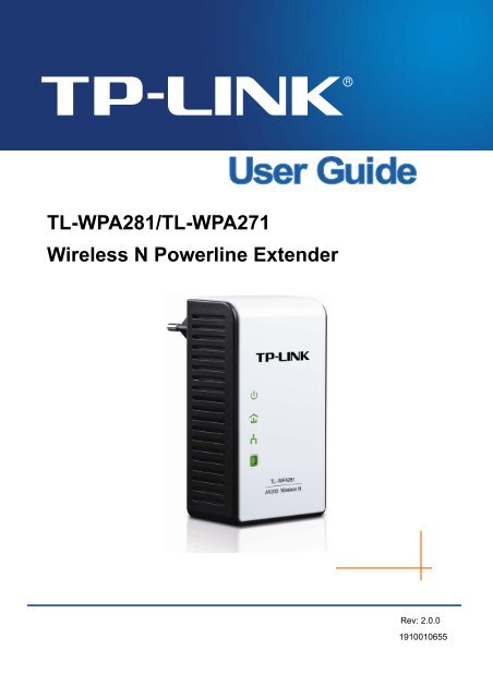
<strong>TL</strong>-WPA281/<strong>TL</strong>-<strong>WPA271</strong><br />
Wireless N Powerline Extender<br />
Rev: 2.0.0<br />
1910010655
COPYRIGHT & TRADEMARKS<br />
Specifications are subject to change without notice.<br />
is a registered trademark of<br />
<strong>TP</strong>-LINK TECHNOLOGIES CO., LTD. Other brands and product names are trademarks or registered<br />
trademarks of their respective holders.<br />
No part of the specifications may be reproduced in any form or by any means or used to make any<br />
derivative such as translation, transformation, or adaptation without permission from <strong>TP</strong>-LINK<br />
TECHNOLOGIES CO., LTD. Copyright © 2012 <strong>TP</strong>-LINK TECHNOLOGIES CO., LTD. All rights<br />
reserved.<br />
http://www.tp-link.com
FCC STATEMENT<br />
This equipment has been tested and found to comply with the limits for a Class B digital device,<br />
pursuant to part 15 of the FCC Rules. These limits are designed to provide reasonable protection<br />
against harmful interference in a residential installation. This equipment generates, uses and can radiate<br />
radio frequency energy and, if not installed and used in accordance with the instructions, may cause<br />
harmful interference to radio communications. However, there is no guarantee that interference will not<br />
occur in a particular installation. If this equipment does cause harmful interference to radio or television<br />
reception, which can be determined by turning the equipment off and on, the user is encouraged to try to<br />
correct the interference by one or more of the following measures:<br />
• Reorient or relocate the receiving antenna.<br />
• Increase the separation between the equipment and receiver.<br />
• Connect the equipment into an outlet on a circuit different from that to which the receiver is<br />
connected.<br />
• Consult the dealer or an experienced radio/ TV technician for help.<br />
This device complies with part 15 of the FCC Rules. Operation is subject to the following two conditions:<br />
1) This device may not cause harmful interference.<br />
2) This device must accept any interference received, including interference that may cause<br />
undesired operation.<br />
Any changes or modifications not expressly approved by the party responsible for compliance could void<br />
the user’s authority to operate the equipment.<br />
Note: The manufacturer is not responsible for any radio or tv interference caused by unauthorized<br />
modifications to this equipment. Such modifications could void the user’s authority to operate the<br />
equipment.<br />
FCC RF Radiation Exposure Statement<br />
This equipment complies with FCC RF radiation exposure limits set forth for an uncontrolled<br />
environment. This device and its antenna must not be co-located or operating in conjunction with any<br />
other antenna or transmitter.<br />
“To comply with FCC RF exposure compliance requirements, this grant is applicable to only Mobile<br />
Configurations. The antennas used for this transmitter must be installed to provide a separation distance<br />
of at least 20 cm from all persons and must not be co-located or operating in conjunction with any other<br />
antenna or transmitter.”<br />
CE Mark Warning<br />
This is a class B product. In a domestic environment, this product may cause radio interference, in which<br />
case the user may be required to take adequate measures.
National restrictions<br />
This device is intended for home and office use in all EU countries (and other countries following the EU<br />
directive 1999/5/EC) without any limitation except for the countries mentioned below:<br />
Country Restriction Reason/remark<br />
Bulgaria<br />
France<br />
None<br />
Outdoor use limited to 10<br />
mW e.i.r.p. within the band<br />
2454-2483.5 MHz<br />
General authorization required for outdoor use and<br />
public service<br />
Military Radiolocation use. Refarming of the 2.4 GHz<br />
band has been ongoing in recent years to allow current<br />
relaxed regulation. Full implementation planned 2012<br />
Italy<br />
Luxembourg<br />
Norway<br />
None<br />
None<br />
Implemented<br />
If used outside of own premises, general authorization is<br />
required<br />
General authorization required for network and service<br />
supply(not for spectrum)<br />
This subsection does not apply for the geographical area<br />
within a radius of 20 km from the centre of Ny-Ålesund<br />
Russian Federation None Only for indoor applications<br />
Note: Please don’t use the product outdoors in France.<br />
Продукт сертифіковано згідно с правилами системи УкрСЕПРО на відповідність вимогам<br />
нормативних документів та вимогам, що передбачені чинними законодавчими актами України.
<strong>TP</strong>-LINK TECHNOLOGIES CO., LTD<br />
DECLARATION OF CONFORMITY<br />
For the following equipment:<br />
Product Description: Wireless N Powerline Extender<br />
Model No.: <strong>TL</strong>-WPA281/<strong>TL</strong>-<strong>WPA271</strong><br />
Trademark: <strong>TP</strong>-LINK<br />
We declare under our own responsibility that the above products satisfy all the technical regulations<br />
applicable to the product within the scope of Council Directives:<br />
Directives 2004 / 108 / EC, Directives 2006 / 95 / EC, Directives 2011/65/EU<br />
The above product is in conformity with the following standards or other normative documents:<br />
EN 55022:2010<br />
EN 55024:2010<br />
EN 61000-3-2:2006+A1:2009+A2:2009<br />
EN 61000-3-3:2008<br />
EN 50412-2-1:2005<br />
EN 60950-1:2006+A11:2009+A1:2010<br />
ETSI EN 300 328 <strong>V1</strong>.7.1: 2006<br />
ETSI EN 301 489-1 <strong>V1</strong>.8.1:2008& ETSI EN 301 489-17 V2.1.1:2009<br />
The product carries the CE Mark<br />
Person is responsible for marking this declaration:<br />
Yang Hongliang<br />
Product Manager of International Business<br />
Date of issue: 2012<br />
<strong>TP</strong>-LINK TECHNOLOGIES CO., LTD.<br />
Building 24 (floors 1, 3, 4, 5), and 28 (floors 1-4) Central Science and Technology Park, Shennan<br />
Rd, Nanshan, Shenzhen, China
Important Safety Instructions<br />
1. Do not open this product or attempt to service it; it may expose you to dangerous high voltage or<br />
other risks.<br />
2. Do not operate this product near water.<br />
3. Do not place or operate this product near a radiator or a heat register.<br />
4. Do not expose this product to dampness, dust or corrosive liquids.<br />
5. Do not connect this product or disconnect it from a wall socket during a lightning or a thunderstorm<br />
6. Do not block the ventilation slots of this product, for insufficient airflow may harm it.<br />
7. Do not put anything on this product.<br />
8. Plug this product directly into a wall socket (100V~240V, 50~60Hz). Do not use an extension cord<br />
between this product and the AC power source.<br />
9. When plugging this product into a wall socket, make sure that the electrical socket is not damaged,<br />
and that there is no gas leakage.<br />
10. Place the connecting cables properly so that people won’t stumble or walk on it.<br />
11. This product should be operated from the type of power indicated on the marking label. If you are not<br />
sure of the type of power available, consult the qualified technician.<br />
12. Unplug this product from the mains and refer the product to qualified service personnel for the<br />
following conditions:<br />
‣ If liquid has been spilled on the product<br />
‣ If the product has been exposed to rain or water<br />
13. Unplug this product from the wall socket before cleaning. Use a damp cloth for cleaning. Do not use<br />
liquid cleaners or aerosol cleaners.<br />
14. The specification of the fuse is T2.5AL250V. To avoid damage, please do not change the fuse.<br />
15. The Operating temperature is 0 ℃ ~40 ℃ (32 ℉ ~104 ℉ ).<br />
The Storage temperature is -40 ℃ ~70℃ (-40 ℉ ~158 ℉ ).
CONTENTS<br />
Chapter 1 Introduction.......................................................................................................................... 1<br />
1.1 System Requirement ..................................................................................................................... 1<br />
1.2 Package Contents ......................................................................................................................... 1<br />
1.3 Conventions................................................................................................................................... 2<br />
Chapter 2 Hardware Connection.......................................................................................................... 3<br />
2.1 Before You Begin........................................................................................................................... 3<br />
2.2 LED Indicator................................................................................................................................. 3<br />
2.3 Physical Interface .......................................................................................................................... 4<br />
2.4 Hardware Connection.................................................................................................................... 5<br />
Chapter 3 Configure the Device........................................................................................................... 8<br />
3.1 Login.............................................................................................................................................. 8<br />
3.2 Status............................................................................................................................................. 9<br />
3.3 WPS .............................................................................................................................................11<br />
3.4 Network ....................................................................................................................................... 17<br />
3.5 Wireless....................................................................................................................................... 18<br />
3.5.1 Wireless Settings ................................................................................................................................18<br />
3.5.2 Wireless Security ................................................................................................................................20<br />
3.5.3 Wireless MAC Filtering ...................................................................................................................... 23<br />
3.5.4 Wireless Advanced............................................................................................................................. 25<br />
3.5.5 Wireless Statistics............................................................................................................................... 26<br />
3.6 Powerline..................................................................................................................................... 27<br />
3.6.1 Network Settings.................................................................................................................................27<br />
3.6.2 Station Settings ...................................................................................................................................28<br />
3.6.3 QoS Setting .........................................................................................................................................29<br />
3.7 System Tools ............................................................................................................................... 30<br />
3.7.1 Firmware Upgrade.............................................................................................................................. 31<br />
3.7.2 Factory Defaults..................................................................................................................................32<br />
3.7.3 Backup & Restore............................................................................................................................... 32<br />
3.7.4 Reboot ..................................................................................................................................................33<br />
3.7.5 Password .............................................................................................................................................33<br />
3.7.6 System Log..........................................................................................................................................34<br />
Chapter 4 Connecting to Wireless Network...................................................................................... 35<br />
4.1 In Windows 7 ............................................................................................................................... 35<br />
4.2 In Windows Vista ......................................................................................................................... 36<br />
4.3 In Windows XP ............................................................................................................................ 38<br />
Chapter 5 Pair Buttons ....................................................................................................................... 40<br />
5.1 Pair (Secure with 128 bits-AES) .................................................................................................. 40<br />
5.2 Setting Up a Powerline Network with the Pair Button .................................................................. 40<br />
5.3 Reset ........................................................................................................................................... 41<br />
Appendix A: Troubleshooting ............................................................................................................ 42<br />
Appendix B: Specifications................................................................................................................ 43
<strong>TL</strong>-WPA281/<strong>TL</strong>-<strong>WPA271</strong><br />
Wireless N Powerline Extender<br />
Chapter 1 Introduction<br />
Congratulations on your purchase of this outstanding Wireless N Powerline Extender. This device is not<br />
only a 200Mbps Powerline Ethernet Adapter which transforms your house’s existing electrical wiring into<br />
a ubiquitous networking infrastructure but also a 300Mbps/150Mbps Wireless N Access Point which<br />
creates a wireless network allowing for greater range and mobility.<br />
As a Powerline Ethernet Adapter, it uses the existing power lines installed in a home as a path to<br />
transmit digital data, voice, audio and video between devices. Simply plug this Wireless N Powerline<br />
Extender into an ordinary AC power outlet, and then your Cable/xDSL broadband connection or existing<br />
Ethernet (LAN) network can be easily extended to any other electrical outlet in any room of a house with<br />
the absence of cabling. With powerline data rates of 200Mbps, full multimedia application can easily be<br />
supported throughout the whole house.<br />
As a Wireless N Access Point, it uses IEEE 802.11n wireless technology and can transmit wireless data<br />
at the rate of up to 300Mbps/150Mbps. With multiple protection measures including SSID broadcast<br />
control, wireless LAN WEP encryption, and WiFi Protected Access (WPA2- PSK, WPA-PSK), the device<br />
delivers complete data privacy.<br />
It supports an easy, Web-based management utility. Even though you may not be familiar with the<br />
device, you can easily configure it with the help of this Guide. The adapter adds two new functions which<br />
are found to be useful.<br />
1. Connection with a new unassociated device via the Pair button.<br />
2. Reset to default settings via the Reset button.<br />
1.1 System Requirement<br />
a) At least two AC 100V ~ 240V power outlets with standard home power wiring<br />
b) A computer with the following:<br />
‣ Operating System of Windows XP, Windows Vista or Windows 7<br />
‣ Operating System with TCP/IP installed<br />
‣ Pentium III compatible processor and above<br />
‣ Ethernet LAN card installed with TCP/IP protocol<br />
‣ 64 MB RAM or more<br />
‣ 50 MB of free disk space (Minimum)<br />
‣ CD-ROM Drive<br />
1.2 Package Contents<br />
The package contains the following items:<br />
‣ One Wireless N Powerline Extender<br />
‣ One Ethernet Cable<br />
‣ One Quick Installation Guide<br />
‣ One Resource CD (including Management Utility and User Guide)<br />
If any of the above items are damaged or missing, please contact your distributor immediately.<br />
1
<strong>TL</strong>-WPA281/<strong>TL</strong>-<strong>WPA271</strong><br />
Wireless N Powerline Extender<br />
1.3 Conventions<br />
The Extender, or <strong>TL</strong>-WPA281/<strong>TL</strong>-<strong>WPA271</strong>, or device mentioned in this User Guide stands for<br />
<strong>TL</strong>-WPA281/<strong>TL</strong>-<strong>WPA271</strong> Wireless N Powerline Extender without any explanations.<br />
Parameters provided in the pictures are just references for setting up the product. They may differ from<br />
the actual situation.<br />
You can set the parameters according to your demand.<br />
Note:<br />
This User Guide is shared by <strong>TL</strong>-WPA281 and <strong>TL</strong>-<strong>WPA271</strong>. Here in this Guide we use <strong>TL</strong>-WPA281 for<br />
example.<br />
The difference between them is:<br />
‣ <strong>TL</strong>-WPA281 Wireless N Powerline Extender with wireless data rate of up to 300Mbps;<br />
‣ <strong>TL</strong>-<strong>WPA271</strong> Wireless N Powerline Extender with wireless data rate of up to 150Mbps.<br />
2
<strong>TL</strong>-WPA281/<strong>TL</strong>-<strong>WPA271</strong><br />
Wireless N Powerline Extender<br />
Chapter 2 Hardware Connection<br />
2.1 Before You Begin<br />
Please read this User Guide carefully before installing and using the equipment. The operating distance<br />
or range of your wireless connection varies significantly based on the physical placement of the<br />
Powerline Extender. Factors that can weaken signals by getting in the way of your network’s radio<br />
waves are metal appliances or obstructions, and walls. Typical ranges vary based on the types of<br />
materials and background RF (radio frequency) noise in your home or office.<br />
For best performance of your wireless network, you are suggested to place your Powerline Extender:<br />
1). Near the center of the area in which your wireless stations will operate.<br />
2). In an elevated location such as a high shelf.<br />
3). Away from the potential sources of interference, such as PCs, microwaves, and cordless phones.<br />
4). With the Antenna in the upright position.<br />
5). Away from large metal surfaces.<br />
Failure to follow these guidelines can result in significant performance degradation or inability to<br />
wirelessly connect to the Powerline Extender.<br />
Note:<br />
Take notes that this Wireless N Powerline Extender works in pairs or with another powerline adapter.<br />
You need to plug the Wireless N Powerline Extender into a power outlet; you will also need another<br />
Wireless N Powerline Extender or Powerline Ethernet Adapter connected to your Cable/xDSL<br />
broadband (Ethernet port) in order to extend your broadband connection or Internet surfing. With clean<br />
powerline, the distance between two Powerline Ethernet Adapters can reach 300 meters, but the actual<br />
distance may vary due to the environment.<br />
Section below describes the Wireless N Powerline Extender’s LED indicators, physical interface and<br />
hardware connection mechanism.<br />
2.2 LED Indicator<br />
The LED indicator displays information about the device’s status.<br />
3
<strong>TL</strong>-WPA281/<strong>TL</strong>-<strong>WPA271</strong><br />
Wireless N Powerline Extender<br />
LEDs Name Status Indication<br />
Power LED<br />
Powerline<br />
LED<br />
Ethernet LED<br />
WiFi/WPS<br />
LED<br />
2.3 Physical Interface<br />
Solid<br />
Off<br />
Solid<br />
Off<br />
Blinking<br />
Solid<br />
Off<br />
Blinking<br />
Solid<br />
Off<br />
Blinking slowly<br />
Blinking quickly<br />
There are four physical items on this device.<br />
The device is on.<br />
The device is off.<br />
The device is connected to a powerline network.<br />
The adapter isn’t connected to any powerline network.<br />
The device is transferring data.<br />
The Ethernet port is connected, but there is no data being<br />
transferred.<br />
The Ethernet port isn’t connected.<br />
The Ethernet port is transferring data.<br />
If the LED becomes solid light for 300 seconds, this<br />
indicates a successful WPS connection.<br />
The wireless function has been disabled.<br />
The device is waiting for client devices to connect to it by<br />
WPS.<br />
The wireless function has been enabled.<br />
4
<strong>TL</strong>-WPA281/<strong>TL</strong>-<strong>WPA271</strong><br />
Wireless N Powerline Extender<br />
WiFi/WPS Button<br />
Ethernet Port<br />
Pair Button<br />
Reset Button<br />
Item<br />
WiFi/WPS<br />
Ethernet<br />
Reset<br />
Pair<br />
Description<br />
Press the button for 2 seconds, the Extender will wait to be connected by WPS.<br />
Pressing the button for 5 seconds will enable or disable the wireless function.<br />
One 10/100Mbps Ethernet port connected to PC LAN card or broadband device.<br />
Use a pin to press and hold this Reset button for approximately 10 seconds, then<br />
the device will restore to factory defaults.<br />
Pair buttons are used to secure a powerline network.<br />
Note:<br />
1. If you press the Pair button for more than 10 seconds, The Extender will leave the network it is<br />
associated with and its network name assumes a random value.<br />
2. For detail information about the Reset button and Pair button, please refer to Chapter 5 Pair<br />
Buttons.<br />
2.4 Hardware Connection<br />
Please first make sure that your PC can successfully access the Internet via the Router. Then connect<br />
the powerline devices following the instructions below.<br />
Step 1: Connecting to the Internet<br />
This section describes how to connect the Powerline Extender into your existing network. Follow the<br />
procedures described below:<br />
1. Connect an Ethernet (RJ45) cable to the Ethernet port of the Powerline Extender or a compatible<br />
Powerline Adapter like <strong>TL</strong>-PA211.<br />
2. Connect the other end of the Ethernet (RJ45) cable to an available Ethernet port of your broadband<br />
Router.<br />
3. Plug the Powerline Extender or Powerline Adapter into a wall socket.<br />
5
<strong>TL</strong>-WPA281/<strong>TL</strong>-<strong>WPA271</strong><br />
Wireless N Powerline Extender<br />
4. Check and confirm the LEDs status. (The Power LED and Ethernet LED on the Powerline Extender<br />
should be ON.)<br />
The hardware connection mechanism is shown below:<br />
Note:<br />
Do not connect the Powerline Extender or Powerline Adapter to an extension lead, power strip,<br />
extension cord, or surge protector as this may degrade the network performance.<br />
Step 2: Connecting the Computer<br />
Following are the steps to properly connect the Powerline Extender to your computer:<br />
1. Connect the provided Ethernet (RJ45) cable to the Powerline Extender’s Ethernet port.<br />
2. Connect the other end of the Ethernet (RJ45) cable to you computer’s LAN port.<br />
3. Plug the Powerline Extender into a wall socket next to the computer.<br />
4. Turn on your computer.<br />
5. Check and confirm that the Power LED and Ethernet LED on the Powerline Extender are ON.<br />
The hardware connection mechanism is shown below:<br />
6
<strong>TL</strong>-WPA281/<strong>TL</strong>-<strong>WPA271</strong><br />
Wireless N Powerline Extender<br />
As soon as the powerline devices are connected following the steps above, a usable powerline network<br />
is available.<br />
7
<strong>TL</strong>-WPA281/<strong>TL</strong>-<strong>WPA271</strong><br />
Wireless N Powerline Extender<br />
Chapter 3 Configure the Device<br />
This Chapter describes how to configure your Access Point via the web-based management page. The<br />
<strong>TL</strong>-WPA281 Wireless N Powerline Extender is easy to configure and manage with the Web-based<br />
(Internet Explorer, Netscape ® Navigator, Firefox, Safari, Opera or Chrome) management page, which<br />
can be launched on any windows, Macintosh or UNIX OS with a web browser.<br />
3.1 Login<br />
1. Insert the <strong>TP</strong>-LINK Resource CD into the CD-ROM drive. The following screen will appear. Select<br />
Wireless N Powerline and then choose Management Utility from the drop-down menu.<br />
Figure 3-1 Setup Wizard<br />
2. Find the model to be configured and click Connect to log in the Web-based management utility.<br />
Figure 3-2 Management Utility<br />
8
<strong>TL</strong>-WPA281/<strong>TL</strong>-<strong>WPA271</strong><br />
Wireless N Powerline Extender<br />
Note:<br />
If another <strong>TL</strong>-WPA281 is displayed on the screen above and you cannot decide which model is the one<br />
you are configuring, please refer to the MAC address under MAC Address column. The device’s MAC<br />
address can be found on the label at the bottom of the device.<br />
3. Enter admin for the User name and Password (both in lower case letters) in the screen below. Then<br />
click OK or press Enter.<br />
Figure 3-3 Login Window<br />
Note:<br />
If the above screen does not prompt, it means that your web-browser has been set to a proxy. Go to<br />
Tools menu>Internet Options>Connections>LAN Settings, in the screen that appears, cancel the<br />
Using Proxy checkbox, and click OK to finish it.<br />
After a successful login, you can configure and manage the device. There are six main menus on the<br />
leftmost column of the Web-based management page: Status, WPS, Network, Wireless, Powerline<br />
and System Tools. Submenus will be available after clicking one of the main menus. On the right of the<br />
Web-based management page lays the detailed explanations and instructions for the corresponding<br />
page.<br />
3.2 Status<br />
The Status page displays the Powerline Extender’s current status and configuration. All information is<br />
read-only.<br />
9
<strong>TL</strong>-WPA281/<strong>TL</strong>-<strong>WPA271</strong><br />
Wireless N Powerline Extender<br />
Figure 3-4 Status<br />
‣ Firmware Version - This field displays the current firmware version of the Powerline Extender.<br />
‣ Hardware Version - This field displays the current hardware version of the Powerline Extender.<br />
‣ Powerline - This field displays the current settings or information for powerline, including the MAC<br />
address, Device Password and Network Name which can be configured on the Powerline →<br />
Network Settings page.<br />
• MAC Address - The physical address of the Powerline Extender, as seen from powerline.<br />
• Device Password - The security ID that restricts access to critical device functions.<br />
• Network Name - The name that identifies a logical network.<br />
‣ Network - The following parameters apply to the Ethernet port of the Powerline Extender. You can<br />
configure them on the Network page.<br />
• MAC Address - The physical address of the Powerline Extender's Ethernet port.<br />
• IP Address - The IP address of the Powerline Extender.<br />
• Subnet Mask - The subnet mask associated with IP address.<br />
‣ Wireless - This field displays the current settings or information for Wireless. They can be<br />
configured on the Wireless → Wireless Settings page.<br />
10
<strong>TL</strong>-WPA281/<strong>TL</strong>-<strong>WPA271</strong><br />
Wireless N Powerline Extender<br />
• Wireless Radio - Indicates whether the wireless radio feature of the Powerline Extender is<br />
enabled or disabled.<br />
• Name (SSID) - The SSID of the Powerline Extender.<br />
• Channel - The wireless channel in use.<br />
• Mode - The current wireless mode the Powerline Extender works on.<br />
• Channel Width - The bandwidth of the wireless channel.<br />
• MAC Address - The physical address of the Powerline Extender, as seen from the WLAN.<br />
‣ System Up Time - This filed displays the length of the time since the Powerline Extender was last<br />
powered on or reset.<br />
Click the Refresh button to get the latest status and settings of the Powerline Extender.<br />
3.3 WPS<br />
WPS (Wi-Fi Protected Setup) can help you quickly and securely connect to a network. This section will<br />
guide you to add a new wireless device to an existing network quickly by WPS function. Select menu<br />
WPS to load the next screen as shown in Figure 3-5.<br />
Figure 3-5 WPS<br />
‣ WPS Status - Enable or disable the WPS function here.<br />
‣ Current PIN - The current value of the Powerline Extender's PIN is displayed here. The default<br />
PIN of the Powerline Extender can be found in the User Guide or on the label at the bottom of the<br />
device.<br />
‣ Restore PIN - Restore the PIN of the device to its default.<br />
‣ Gen New PIN - Click this button, and then you can get a new random value for the device's PIN.<br />
You can ensure the network security by generating a new PIN.<br />
‣ Add device - You can add a new device to the existing network manually by clicking this button.<br />
To add a new device:<br />
If a wireless adapter supports Wi-Fi Protected Setup (WPS) or QSS (Quick Secure Setup) you can<br />
establish a wireless connection between the wireless adapter and the Powerline Extender using either<br />
Push Button Configuration (PBC) method or PIN method.<br />
Note:<br />
To build a successful connection by WPS, you should also do corresponding configuration on the new<br />
device meanwhile.<br />
For the configuration of the new device, here takes the Wireless Adapter of our company for example.<br />
11
<strong>TL</strong>-WPA281/<strong>TL</strong>-<strong>WPA271</strong><br />
Wireless N Powerline Extender<br />
I. By PBC<br />
If the wireless adapter supports Wi-Fi Protected Setup and the Push Button Configuration (PBC)<br />
method, you can add it to the network by PBC with the following two methods.<br />
Method One:<br />
Step 1: Press the WPS button on the front panel of the device for 2 seconds.<br />
Step 2: Within two minutes, press and hold the QSS button of the adapter directly for 2 or 3 seconds.<br />
(QSS, also called WPS, is used by our company on the wireless adapter.)<br />
Step 3:<br />
Wait for a while until the next screen appears. Click Finish to complete the WPS configuration.<br />
The status LED on the Powerline Extender will light green for five minutes if the device has<br />
been successfully added to the network.<br />
The WPS Configuration Screen of Wireless Adapter<br />
12
<strong>TL</strong>-WPA281/<strong>TL</strong>-<strong>WPA271</strong><br />
Wireless N Powerline Extender<br />
Method Two:<br />
Step 1: Press the WPS button on the front panel of the device for 2 seconds.<br />
Step 2: For the configuration of the wireless adapter, please choose Push the button on my access<br />
point in the configuration utility of the WPS as below, and click Next. (QSS, also called WPS, is<br />
used by our company on the wireless adapter.)<br />
The WPS Configuration Screen of Wireless Adapter<br />
Step 3: Wait for a while until the next screen appears. Click Finish to complete the WPS configuration.<br />
The status LED on the Powerline Extender will light green for five minutes if the device has<br />
been successfully added to the network.<br />
13
<strong>TL</strong>-WPA281/<strong>TL</strong>-<strong>WPA271</strong><br />
Wireless N Powerline Extender<br />
The WPS Configuration Screen of Wireless Adapter<br />
Method Three:<br />
Step 1:<br />
Keep the default WPS Status as Enabled and click the Add device button in Figure 3-5, then<br />
the following screen will appear.<br />
Figure 3-6 Add a New Device<br />
Step 2:<br />
Step 3:<br />
Choose Press the button of the new device in two minutes and click Connect.<br />
For the configuration of the wireless adapter, please choose Push the button on my access<br />
point in the configuration utility of the WPS as below, and click Next. (QSS, also called WPS,<br />
is used by our company on the wireless adapter.)<br />
14
<strong>TL</strong>-WPA281/<strong>TL</strong>-<strong>WPA271</strong><br />
Wireless N Powerline Extender<br />
The WPS Configuration Screen of Wireless Adapter<br />
Step 4:<br />
Wait for a while until the next screen appears. Click Finish to complete the WPS configuration.<br />
The status LED on the Powerline Extender will light green for five minutes if the device has<br />
been successfully added to the network.<br />
The WPS Configuration Screen of Wireless Adapter<br />
II. By PIN<br />
If the new device supports Wi-Fi Protected Setup and the PIN method, you can add it to the network by<br />
PIN with the following two methods.<br />
Method One: Enter the PIN into my Powerline Extender<br />
Step 1: Keep the default WPS Status as Enabled and click the Add device button in Figure 3-5, then<br />
the following screen will appear.<br />
15
<strong>TL</strong>-WPA281/<strong>TL</strong>-<strong>WPA271</strong><br />
Wireless N Powerline Extender<br />
Figure 3-7 Add a New Device<br />
Step 2: Choose Enter the new device's PIN and enter the PIN code (take 16952898 for example) of<br />
the wireless adapter in the field after PIN as shown in the figure above. Then click Connect.<br />
Note:<br />
The PIN code of the adapter is always displayed on the WPS configuration screen as shown in the<br />
following figure.<br />
Step 3: For the configuration of the wireless adapter, please choose Enter a PIN into my access point<br />
or a registrar in the configuration utility of the WPS as below, and click Next. (QSS, also called<br />
WPS, is used by our company on the wireless adapter.)<br />
Note:<br />
The WPS Configuration Screen of Wireless Adapter<br />
In this example, the default PIN code of this adapter is 16952898 as the above figure shows.<br />
Method Two: Enter the PIN from my Powerline Extender<br />
Step 1: Get the Current PIN code of the Powerline Extender in Figure 3-5 (Each Powerline Extender<br />
has its unique PIN code. Here takes the PIN code 12345670 of this device for example).<br />
Step 2: For the configuration of the wireless adapter, please choose Enter a PIN from my access<br />
point in the configuration utility of the WPS as below, and enter the PIN code of the Extender<br />
into the field after Access Point PIN. Then click Next. (QSS, also called WPS, is used by our<br />
company on the wireless adapter.)<br />
16
<strong>TL</strong>-WPA281/<strong>TL</strong>-<strong>WPA271</strong><br />
Wireless N Powerline Extender<br />
The WPS Configuration Screen of Wireless Adapter<br />
Note:<br />
The default PIN code of the Powerline Extender can be found on its label or on its WPS configuration<br />
page as shown in Figure 3-5.<br />
You will see the following screen when the new device has successfully connected to the network.<br />
Figure 3-8 Successfully Added a New Device<br />
Note:<br />
a. The WPS LED on the Powerline Extender will light green for five minutes if the device has been<br />
successfully added to the network.<br />
b. The WPS function cannot be configured if the Wireless function of the Powerline Extender is<br />
disabled. Please make sure the wireless function is enabled before configuring the WPS.<br />
3.4 Network<br />
You can configure the IP parameters of the Powerline Extender on this page.<br />
Figure 3-9 Network<br />
17
<strong>TL</strong>-WPA281/<strong>TL</strong>-<strong>WPA271</strong><br />
Wireless N Powerline Extender<br />
‣ MAC Address - The physical address of the Powerline Extender's Ethernet port. The value can not<br />
be changed.<br />
‣ IP Address - Enter the IP address of the Powerline Extender in dotted-decimal notation (factory<br />
default setting is 192.168.1.1).<br />
‣ Subnet Mask - An address code that determines the size of the network. Usually it is<br />
255.255.255.0.<br />
Click the Save button to save your settings.<br />
Note:<br />
If you change the IP address, you must use the new IP address to log in to the Powerline Extender.<br />
3.5 Wireless<br />
The Wireless option, improving functionality and performance for wireless network, can help you make<br />
the Powerline Extender an ideal solution for your wireless network. Here you can create a wireless local<br />
area network just through a few settings. Wireless Settings is used for the configuration of some basic<br />
parameters of the Powerline Extender. Wireless Security provides three different security types to<br />
secure your data and thus providing greater security for your wireless network. MAC filtering allows you<br />
to control the access of wireless stations to the Powerline Extender. Wireless Advanced allows you to<br />
configure some advanced parameters for the Powerline Extender. Wireless statistics enables you to get<br />
detailed information about the current connected wireless stations.<br />
There are five submenus under the Wireless menu (shown in Figure 3-10): Wireless Settings,<br />
Wireless Security, Wireless MAC Filtering, Wireless Advanced and Wireless Statistics. Click any<br />
of them and you will be able to configure the corresponding function. The detailed explanations for each<br />
submenu are provided below.<br />
3.5.1 Wireless Settings<br />
Figure 3-10 Wireless menu<br />
Selecting Wireless > Wireless Settings will enable you to configure the basic settings for your wireless<br />
network on the screen below (Figure 3-11).<br />
18
<strong>TL</strong>-WPA281/<strong>TL</strong>-<strong>WPA271</strong><br />
Wireless N Powerline Extender<br />
Figure 3-11 Wireless Settings<br />
‣ SSID (Set Service Identifier) - Identifies your wireless network name. Enter a value of up to 32<br />
characters. The same Name (SSID) must be assigned to all wireless devices in your network. The<br />
default SSID is <strong>TP</strong>-LINK_XXXXXX (XXXXXX indicates the last six unique characters of each<br />
device’s MAC address). This value is case-sensitive. For example, TEST is not the same as test.<br />
‣ Region - Select your region from the pull-down list. This field specifies the region where the<br />
wireless function of the Powerline Extender can be used. It may be illegal to use the wireless<br />
function of the Powerline Extender in a region other than one of those specified in this filed. If your<br />
country or region is not listed, please contact your local government agency for assistance.<br />
When you select your local region from the pull-down list, click the Save button, then the Note<br />
Dialog appears. Click OK.<br />
Note Dialog<br />
‣ Channel - This field determines which operating frequency will be used. It is not necessary to<br />
change the wireless channel unless you notice interference problems with another nearby access<br />
point. If you select Auto, then the Powerline Extender will choose the best channel automatically.<br />
‣ Mode - Select the desired wireless mode. The options are:<br />
• 11b only - Only 802.11b wireless stations can connect to the device.<br />
• 11g only - Only 802.11g wireless stations can connect to the device.<br />
• 11n only - Only 802.11n wireless stations can connect to the device.<br />
19
<strong>TL</strong>-WPA281/<strong>TL</strong>-<strong>WPA271</strong><br />
Wireless N Powerline Extender<br />
• 11bg mixed - Both 802.11b and 802.11g wireless stations can connect to the device.<br />
• 11bgn mixed - All 802.11b, 802.11g and 802.11n wireless stations can connect to the device.<br />
If all of the wireless devices connected with the Powerline Extender can connect in the same<br />
transmission mode (eg. 802.11b), you can choose the Only mode (eg. 11b only). If you have some<br />
devices that use different transmission modes, choose the appropriate Mixed mode.<br />
‣ Channel Width - Determines the channel width to be used. It is unnecessary to change the default<br />
value unless required.<br />
‣ Max Tx Rate - Specifies the maximum transmit rate of the device through this field.<br />
‣ Enable Wireless Powerline Extender Radio - The wireless radio of the Powerline Extender can<br />
be enabled or disabled to allow or deny wireless stations to access. If it is enabled, the wireless<br />
stations will be able to access the Powerline Extender; otherwise, wireless stations will not be able<br />
to access the Powerline Extender.<br />
‣ Enable SSID Broadcast - Selecting this check box will allow the device to broadcast its name<br />
(SSID) on the air. If it’s allowed, when wireless clients survey the local area for wireless networks<br />
to associate with, they will detect the SSID broadcast by the device.<br />
Note:<br />
To apply any settings you have altered on the page, please click the Save button, and then you will be<br />
reminded to reboot the device.<br />
3.5.2 Wireless Security<br />
Selecting Wireless > Wireless Security will enable you to configure wireless security for your wireless<br />
network to protect your data from intruders. The Powerline Extender provides three security types: WEP,<br />
WPA/WPA2 and WPA-PSK/WPA2-PSK. Wireless security can be set on the following screen shown as<br />
Figure 3-12.<br />
20
<strong>TL</strong>-WPA281/<strong>TL</strong>-<strong>WPA271</strong><br />
Wireless N Powerline Extender<br />
Figure 3-12 Wireless Security<br />
‣ Disable Security - Check this radio button to disable wireless security. If disabled, the wireless<br />
stations will be able to connect this device without encryption. It is strongly recommended that you<br />
choose one of the security types to enable security.<br />
‣ WEP - Select 802.11 WEP security.<br />
Figure 3-13 WEP<br />
• Type - You can select one of following types.<br />
<br />
<br />
<br />
Automatic - Select Shared Key or Open System authentication type automatically based<br />
on the wireless station's capability and request.<br />
Shared Key - Select 802.11 Shared Key authentication type.<br />
Open System - Select 802.11 Open System authentication.<br />
21
<strong>TL</strong>-WPA281/<strong>TL</strong>-<strong>WPA271</strong><br />
Wireless N Powerline Extender<br />
• WEP Key Format - You can select ASCII or Hexadecimal format. ASCII format stands for any<br />
combination of keyboard characters in the specified length. Hexadecimal format stands for any<br />
combination of hexadecimal digits (0-9, a-f, A-F) in the specified length.<br />
• WEP Key - Select which of the four keys will be used and enter the matching WEP key<br />
information for your network in the selected key radio button. These values must be identical on<br />
all wireless stations in your network.<br />
• Key Type - You can select the WEP key length (64-bit, or 128-bit) for encryption. "Disabled"<br />
means this WEP key entry is invalid.<br />
<br />
<br />
For 64-bit encryption - You can enter 10 hexadecimal digits (any combination of 0-9, a-f,<br />
A-F, zero key is not permitted) or 5 ASCII characters.<br />
For 128-bit encryption - You can enter 26 hexadecimal digits (any combination of 0-9, a-f,<br />
A-F, zero key is not permitted) or 13 ASCII characters.<br />
Note:<br />
If you do not set the key, the wireless security function is still disabled even if you have selected Shared<br />
Key as Authentication Type.<br />
‣ WPA/WPA2 - Select WPA/WPA2 based on Radius Server.<br />
Figure 3-14 WPA/WPA2<br />
• Version - You can select one of following versions.<br />
<br />
<br />
Automatic - Select WPA or WPA2 automatically based on the wireless station's capability<br />
and request.<br />
WPA - Wi-Fi Protected Access.<br />
WPA2 - WPA version 2.<br />
• Encryption - You can select either Automatic, TKIP or AES.<br />
• Radius Server IP - Enter the IP address of the Radius Server.<br />
• Radius Port - Enter the port used by radius service.<br />
• Radius Password - Enter the password for the Radius Server.<br />
• Group Key Update Period - Specify the group key update interval in seconds. The value can<br />
be either 0 or at least 30. Enter 0 to disable the update.<br />
‣ WPA-PSK/ WPA2-PSK - Select WPA based on pre-shared key.<br />
22
<strong>TL</strong>-WPA281/<strong>TL</strong>-<strong>WPA271</strong><br />
Wireless N Powerline Extender<br />
Figure 3-15 WPA-PSK/WPA2-PSK<br />
• Version - You can select one of following versions.<br />
<br />
<br />
<br />
Automatic - Select WPA-PSK or WPA2-PSK automatically based on the wireless station's<br />
capability and request.<br />
WPA-PSK - Pre-shared key of WPA.<br />
WPA2-PSK - Pre-shared key of WPA2.<br />
• Encryption - When you select WPA-PSK or WPA2-PSK for Authentication Type, you can<br />
select either Automatic, TKIP or AES as Encryption.<br />
• PSK Passphrase - Enter a passphrase here.<br />
• Group Key Update Period - Specify the group key update interval in seconds. The value can<br />
be either 0 or at least 30. Enter 0 to disable the update.<br />
Be sure to click the Save button to save your settings on this page.<br />
Note:<br />
You will be reminded to reboot the device after clicking the Save button.<br />
3.5.3 Wireless MAC Filtering<br />
Selecting Wireless > Wireless MAC Filtering will allow you to set up some filtering rules to control<br />
wireless stations accessing the device, which depends on the station’s MAC address on the following<br />
screen as shown in Figure 3-16.<br />
Figure 3-16 Wireless MAC Filtering<br />
‣ Wireless MAC Filtering - Click the Enable button to enable the Wireless MAC Address Filtering.<br />
The default setting is disabled.<br />
23
<strong>TL</strong>-WPA281/<strong>TL</strong>-<strong>WPA271</strong><br />
Wireless N Powerline Extender<br />
To Add a Wireless MAC Address filtering entry, click the Add New… button. The “Add or Modify<br />
Wireless MAC Address Filtering entry" page will appear, shown in Figure 3-17.<br />
Figure 3-17 Add or Modify Wireless MAC Address Filtering entry<br />
‣ MAC Address - Enter the wireless station's MAC address that you want to control.<br />
‣ Description - Give a simple description of the wireless station.<br />
‣ Status - Select a status for this entry, either Enabled or Disabled.<br />
To set up an entry, follow these instructions:<br />
First, you must decide whether the unspecified wireless stations can access the device or not. If you<br />
desire that the unspecified wireless stations can access the device, please select the radio button Allow<br />
the stations not specified by any enabled entries in the list to access, otherwise, select the radio<br />
button Deny the stations not specified by any enabled entries in the list to access.<br />
To add a MAC Address Filtering entry, follow these instructions:<br />
1. Enter the appropriate MAC Address into the MAC Address field. The format of the MAC Address is<br />
XX-XX-XX-XX-XX-XX (X is any hexadecimal digit). For example: 00-0A-EB-B0-00-0B.<br />
2. Enter a simple description of the wireless station in the Description field. For example: wireless<br />
station A.<br />
3. Select Enabled or Disabled for this entry on the Status pull-down list.<br />
4. Click the Save button to save this entry.<br />
To add additional entries, repeat steps 1-4.<br />
To modify or delete an existing entry:<br />
1. Click the Modify in the entry you want to modify. If you want to delete the entry, click the Delete.<br />
2. Modify the information.<br />
3. Click the Save button.<br />
Click the Enable All button to make all entries enabled<br />
Click the Disabled All button to make all entries disabled.<br />
24
<strong>TL</strong>-WPA281/<strong>TL</strong>-<strong>WPA271</strong><br />
Wireless N Powerline Extender<br />
Click the Delete All button to delete all entries<br />
Click the Next button to go to the next page and click the Previous button to return to the previous page.<br />
For example: If you desire that the wireless station A with MAC address 00-0A-EB-00- 07-BE is able to<br />
access the device, while all other wireless stations cannot access the device, you should configure the<br />
Wireless MAC Address Filtering list by following these steps:<br />
1. Click the Enable button to enable this function.<br />
2. Select the radio button: Deny the stations not specified by any enabled entries in the list to<br />
access for Filtering Rules.<br />
3. Delete all or disable all entries if there are any entries already.<br />
4. Click the Add New... button and enter the MAC address 00-0A-EB-00-07-BE in the MAC Address<br />
field, enter Wireless Station A in the Description field and select Enabled in the Status pull-down<br />
list. Click the Save button.<br />
The filtering rules that configured should be similar to the following list:<br />
Note:<br />
If you enable the function and select Deny the stations not specified by any enabled entries in the<br />
list to access for Filtering Rules but there isn’t any enabled entry in the list, thus, no wireless stations<br />
can access the device.<br />
3.5.4 Wireless Advanced<br />
Selecting Wireless > Wireless Advanced will allow you to do some advanced settings for the device in<br />
the following screen shown in Figure 3-18. As the configuration for each operation mode is almost the<br />
same, we take Access Point mode for example here.<br />
Figure 3-18 Wireless Advanced<br />
25
<strong>TL</strong>-WPA281/<strong>TL</strong>-<strong>WPA271</strong><br />
Wireless N Powerline Extender<br />
‣ Transmit Power - Specifies the transmit power of the device. You can select High, Middle or Low<br />
based on your need. High is the default setting and is recommended.<br />
‣ Beacon Interval - Specifies a value between 40-1000 milliseconds. The beacons are the packets<br />
sent by the device to synchronize a wireless network. Beacon Interval value determines the time<br />
interval of the beacons. The default value is 100.<br />
‣ RTS Threshold - Specifies the RTS (Request to Send) Threshold. If the packet is larger than the<br />
specified RTS Threshold size, the device will send RTS frames to a particular receiving station and<br />
negotiate the sending of a data frame. The default value is 2346.<br />
‣ Fragmentation Threshold - This value is the maximum size determining whether packets will be<br />
fragmented. Setting the Fragmentation Threshold too low may result in poor network performance<br />
since excessive packets. 2346 is the default setting and is recommended.<br />
‣ DTIM Interval - Determines the interval of the Delivery Traffic Indication Message (DTIM). You can<br />
specify the value between 1-255 Beacon Intervals. The default value is 1, which indicates the<br />
DTIM Interval is the same as Beacon Interval.<br />
‣ Enable WMM - WMM function can guarantee the packets with high- priority messages being<br />
transmitted preferentially. It is strongly recommended that this function be enabled.<br />
‣ Enable Short GI - This function is recommended for it will increase the data capacity by reducing<br />
the guard interval time.<br />
‣ Enable AP Isolation - Isolates all connected wireless stations so that wireless stations cannot<br />
access each other through WLAN. This function will be disabled if WDS/Bridge is enabled.<br />
Note:<br />
If you are not familiar with the setting items on this page, it's strongly recommended that you keep the<br />
provided default values; otherwise, it may result in low wireless network performance.<br />
3.5.5 Wireless Statistics<br />
Selecting Wireless > Wireless Statistics will allow you to see the wireless transmission information in<br />
the following screen shown in Figure 3-19. This page shows MAC Address, Current Status, Received<br />
Packets and Sent Packets for each connected wireless station.<br />
Figure 3-19 Statistics of the device attached wireless stations<br />
‣ MAC Address - Shows the connected wireless station's MAC address.<br />
‣ Current Status - The connected wireless station's running status, one of STA-AUTH / STA-ASSOC<br />
/ STA-JOINED / WPA / WPA-PSK / WPA2 / WPA2-PSK / AP-UP / AP-DOWN / Disconnected.<br />
26
<strong>TL</strong>-WPA281/<strong>TL</strong>-<strong>WPA271</strong><br />
Wireless N Powerline Extender<br />
‣ Received Packets - Packets received by the station.<br />
‣ Sent Packets - Packets sent by the station.<br />
You cannot change any of the values on this page. To update this page and to show the current<br />
connected wireless stations, click the Refresh button.<br />
If the numbers of connected wireless stations go beyond one page, click the Next button to go to the<br />
next page and click the Previous button to return to the previous page.<br />
Note:<br />
This page will be refreshed automatically every 5 seconds.<br />
3.6 Powerline<br />
There are three submenus under the Powerline menu (shown in Figure 3-10): Network Settings,<br />
Station Settings and QoS Setting. Click any of them, and you will be able to configure the<br />
corresponding function. The detailed explanations for each submenu are provided below.<br />
3.6.1 Network Settings<br />
Figure 3-20 Wireless menu<br />
Selecting Powerline > Network Settings, and you can configure the network name of the Powerline<br />
Extender or all the stations in current network on this page.<br />
Figure 3-21 Network Settings<br />
‣ MAC Address - The physical address of the Powerline Extender, as seen from the powerline. The<br />
value can not be changed.<br />
‣ Device Password - The password of the Powerline Extender. The value can not be changed.<br />
‣ Network Name - Enter the network name (factory default - HomePlugAV).<br />
Click the Default button to enter the default network name.<br />
Click the Set Local button to set the Powerline Extender.<br />
Click the Set All button to set all stations which entered the correct passwords in current network,<br />
including the Powerline Extender.<br />
27
<strong>TL</strong>-WPA281/<strong>TL</strong>-<strong>WPA271</strong><br />
Wireless N Powerline Extender<br />
Note:<br />
If you set all stations network name, the remote ones which power off or entered the wrong password<br />
will not take effect.<br />
3.6.2 Station Settings<br />
The Station Settings page shows remote stations in current network and allows you to enter, modify or<br />
delete the password and name for each station.<br />
Figure 3-22 Station Settings<br />
‣ MAC Address - The remote station's MAC address. The value can not be changed.<br />
‣ Device Password - The security ID of remote station.<br />
‣ Device Name - The name used for identifing a station.<br />
To add or modify a station entry, click the Add or Modify button in operation column and following these<br />
instructions:<br />
1. Enter the station password in Device Password field. The format of the password is<br />
XXXX-XXXX-XXXX-XXXX (X is any character). For example, RLXL-BYPI-MZBO-OPAB.<br />
2. Enter a name you want to give the station in the Device Name field or leave it empty. For<br />
example, Station A.<br />
3. Click the Save button to save this entry.<br />
To add or modify another entries, repeat steps 1~3.<br />
Figure 3-23 Add or Modify PLC Station entry<br />
Click the Delete button in the operation column to delete a station entry.<br />
28
<strong>TL</strong>-WPA281/<strong>TL</strong>-<strong>WPA271</strong><br />
Wireless N Powerline Extender<br />
Click the Add New... button to add a station into current network. The steps are the same as adding a<br />
station entry.<br />
Figure 3-24 Add a new station<br />
Click the Refresh button to update the current connected stations.<br />
Click the Next button to go to the next page and click the Previous button to return to the previous<br />
page.<br />
Note:<br />
You can do Add or Modify operation only when the remote station is connected. If the remote station<br />
which you entered the password is power off or leave the current network, you can only do Delete<br />
operation.<br />
3.6.3 QoS Setting<br />
You can configure the QoS parameters of the Powerline Extender on this page.<br />
29
<strong>TL</strong>-WPA281/<strong>TL</strong>-<strong>WPA271</strong><br />
Wireless N Powerline Extender<br />
Figure 3-25 QoS Setttings<br />
‣ Simple Application Mapping - The group allows you to choose what type of traffic with the highest<br />
user priority you will use your local device for by pitching on one of the following four radios.<br />
• Internet - The Internet Application Mapping be use to Internet server.<br />
• Online Game - The Online Game Application Mapping be use to Online Game server.<br />
• Audio or Video - The Audio or Video Application Mapping be use to Audio or Video server.<br />
• Voice over IP - The Voice over IP Application Mapping be use to Voice over IP server.<br />
‣ Advanced Priority Mapping: The group sets VLAN priority and TOS priority to CAP mapping and<br />
other priority.<br />
• VLAN Tages - Host frames can be priority classified based on VLAN CoS bits. Each<br />
combination of the CoS bits can be independently assigned to a priority queue.<br />
• TOS Bits - Classification can be based on TOS priority bits in the same manner as the VLAN<br />
CoS bits.<br />
• Unicast Priority - Unicast frames are those destined to a unique MAC addresses. These<br />
frames to CAP1 by default.<br />
• Mcast Priority - Multicast frames not managed by IGMP and broadcast frames such as ARP<br />
frames are transmitted at the specified priority, default is CAP1.<br />
30
<strong>TL</strong>-WPA281/<strong>TL</strong>-<strong>WPA271</strong><br />
Wireless N Powerline Extender<br />
• IGMP Priority - IGMP frames are defined by the Internet Group Management Protocol and<br />
represent management messages passed between various network infrastructure<br />
components.As a management protocol, these frames are by default classified at the highest<br />
CAP3 by default.<br />
• AV Stream Priority - AV Stream is placed in the specified priority queue, default is CAP2.<br />
Note:<br />
1. CAP3 is the highest priority while CAP0 is the lowest priority.CAP3 is used for the delivery of voice<br />
and urgent MMEs and control messages such as IGMP and MLD,CAP2 is used for the delivery of<br />
video and non urgent MMEs, CAP0 and CAP1 are used for delivery of best effort data.<br />
2. If both VLAN and TOS are enabled and a frame is found that contains both, VLAN Tags will<br />
override TOS Bits.<br />
Click the Save button to save your settings.<br />
3.7 System Tools<br />
System Tools option helps you to optimize the configuration of your device. You can upgrade the<br />
Powerline Extender to the latest version of firmware as well as backup or restore the device’s<br />
configuration files. It’s suggested that you change the default password to a more secure one because it<br />
controls access to the device’s web-based management page. Besides, you can find out what<br />
happened to the system in System Log.<br />
There are six submenus under the System Tools menu (shown as Figure 3-26): Firmware Upgrade,<br />
Factory Defaults, Backup & Restore, Reboot, Password and System Log. Clicking any of them will<br />
enable you to configure the corresponding function. The detailed explanations for each submenu are<br />
provided below.<br />
3.7.1 Firmware Upgrade<br />
Figure 3-26 The System Tools menu<br />
Selecting System Tools > Firmware Upgrade allows you to upgrade the latest version of firmware for<br />
the device on the screen shown in Figure 3-27.<br />
31
<strong>TL</strong>-WPA281/<strong>TL</strong>-<strong>WPA271</strong><br />
Wireless N Powerline Extender<br />
Figure 3-27 Firmware Upgrade<br />
New firmware versions are posted at http://www.tp-link.com and can be downloaded for free.<br />
‣ Firmware Version - Here displays the current firmware version.<br />
‣ Hardware Version - Here displays the current hardware version. The hardware version of the<br />
upgrade file must accord with the current hardware version.<br />
Note:<br />
1 There is no need to upgrade the firmware unless the new firmware has a new feature you want to<br />
use. However, when experiencing problems caused by the device itself, you can try to upgrade the<br />
firmware.<br />
2 Before upgrading the device’s firmware, you should write down some of your customized settings to<br />
avoid losing important configuration settings of device.<br />
To upgrade the device's firmware, follow these instructions:<br />
1. Download a more recent firmware upgrade file from the <strong>TP</strong>-LINK website (http://www.tp-link.com).<br />
2. Enter the path name or click Browse… to select the downloaded file on the computer into the File<br />
blank.<br />
3. Click Upgrade.<br />
4. The Powerline Extender will reboot while the upgrading has been finished.<br />
Note:<br />
The firmware version must correspond to the hardware. The upgrade process takes a few moments and<br />
the Powerline Extender restarts automatically when the upgrade is complete. It is important to keep<br />
power applied during the entire process. Loss of power during the upgrade could damage the Powerline<br />
Extender.<br />
32
<strong>TL</strong>-WPA281/<strong>TL</strong>-<strong>WPA271</strong><br />
Wireless N Powerline Extender<br />
3.7.2 Factory Defaults<br />
Selecting System Tools > Factory Defaults allows you to restore the factory default settings for the<br />
device on the screen shown in Figure 3-28.<br />
Figure 3-28 Restore Factory Defaults<br />
Click Restore to reset all configuration settings to their default values.<br />
• Default User Name: admin<br />
• Default Password: admin<br />
• Default IP Address: 192.168.1.1<br />
• Default Subnet Mask: 255.255.255.0<br />
Note:<br />
Any settings you have saved will be lost when the default settings are restored.<br />
3.7.3 Backup & Restore<br />
Selecting System Tools > Backup & Restore allows you to save all configuration settings to your local<br />
computer as a file or restore the device's configuration on the screen shown in Figure 3-29.<br />
Figure 3-29 Save or Restore the Configuration<br />
Click Backup to save all configuration settings to your local computer as a file.<br />
To restore the device's configuration, follow these instructions:<br />
• Click Browse… to find the configuration file which you want to restore.<br />
• Click Restore to update the configuration with the file whose path is the one you have input or<br />
selected in the blank.<br />
Note:<br />
1. The current configuration will be covered with the uploading configuration file.<br />
2. Wrong process will lead the device unmanaged.<br />
3. The restoring process lasts for about 20 seconds and restarts automatically. Do not power off the<br />
33
<strong>TL</strong>-WPA281/<strong>TL</strong>-<strong>WPA271</strong><br />
Wireless N Powerline Extender<br />
device during the process to avoid any damage.<br />
3.7.4 Reboot<br />
Selecting System Tools > Reboot allows you to reboot the device on the screen shown in Figure 3-30.<br />
Click the Reboot button to reboot the device.<br />
Figure 3-30 Reboot the device<br />
Some settings of the device will take effect only after rebooting, which include:<br />
• Change the Powerline Extender's IP Address (system will reboot automatically).<br />
• Change the Wireless configurations.<br />
• Upgrade the firmware of the Powerline Extender (system will reboot automatically).<br />
• Restore the Powerline Extender's settings to the factory defaults (system will reboot<br />
automatically).<br />
• Update the configuration with the file (system will reboot automatically).<br />
3.7.5 Password<br />
Selecting System Tools > Password allows you to change the factory default user name and password<br />
of the device on the screen shown in Figure 3-31.<br />
Figure 3-31 Password<br />
It is strongly recommended that you change the factory default user name and password of the device.<br />
All users who try to access the device's web-based management page or Quick Setup will be prompted<br />
for the device's user name and password.<br />
Note:<br />
The new user name and password must not exceed 14 characters in length and must not include any<br />
34
<strong>TL</strong>-WPA281/<strong>TL</strong>-<strong>WPA271</strong><br />
Wireless N Powerline Extender<br />
spaces. Enter the new Password again to confirm it.<br />
Click Save when finished.<br />
Click Clear All to clear all.<br />
3.7.6 System Log<br />
Selecting System Tools > System Log allows you to query the Logs of the device on the screen shown<br />
in Figure 3-32.<br />
Figure 3-32 System Log<br />
The device can keep logs of all traffic. You can query the logs to find what happened to the device.<br />
Click the Refresh button to show the latest log list.<br />
Click the Clear All button to clear all logs.<br />
35
<strong>TL</strong>-WPA281/<strong>TL</strong>-<strong>WPA271</strong><br />
Wireless N Powerline Extender<br />
Chapter 4 Connecting to Wireless Network<br />
4.1 In Windows 7<br />
Windows 7 users may use the built-in wireless utility. Follow the steps below.<br />
1. Left-click the wireless icon in your system tray (lower-right corner). The utility will display any<br />
available wireless networks in your area. Select the wireless network (displayed using the SSID) to<br />
be connected and then click Connect.<br />
Figure 4-1<br />
2. If the network you would like to connect is security-enabled, enter the same security key or<br />
passphrase that is on your router; or push the WPS button on the router or access point (You will be<br />
prompted to push the button on the window if WPS function is supported as shown in the figure<br />
below). If the network to be connected is not secure, the connection will be built without entering a<br />
key.<br />
36
<strong>TL</strong>-WPA281/<strong>TL</strong>-<strong>WPA271</strong><br />
Wireless N Powerline Extender<br />
Figure 4-2<br />
3. You have joined the home network and can surf the Internet now.<br />
4.2 In Windows Vista<br />
Figure 4-3<br />
Windows Vista users may use the built-in wireless utility. Follow the steps below.<br />
1. Open the wireless utility by right-clicking on the wireless computer icon in your system tray as<br />
shown in the figure below. Select Connect to a network.<br />
37
<strong>TL</strong>-WPA281/<strong>TL</strong>-<strong>WPA271</strong><br />
Wireless N Powerline Extender<br />
Figure 4-4<br />
2. The utility will display any available wireless networks in your area. Select the wireless network you<br />
would like to connect and then click Connect.<br />
Figure 4-5<br />
3. If the network you would like to connect is security-enabled, enter the same security key or<br />
passphrase that is on your router. If the network to be connected is not secure, the connection will<br />
be built without entering a key.<br />
38
<strong>TL</strong>-WPA281/<strong>TL</strong>-<strong>WPA271</strong><br />
Wireless N Powerline Extender<br />
Figure 4-6<br />
4. You have joined the home network and can surf the Internet now. Click close to finish the<br />
connection.<br />
4.3 In Windows XP<br />
Figure 4-7<br />
Windows XP users may use the built-in wireless utility. Follow the steps below.<br />
1. Right-click on the wireless computer icon in your system tray (lower-right corner). Select View<br />
Available Wireless Networks.<br />
39
<strong>TL</strong>-WPA281/<strong>TL</strong>-<strong>WPA271</strong><br />
Wireless N Powerline Extender<br />
Figure 4-8<br />
2. The utility will display any available wireless networks in your area. Click on a network (displayed<br />
using the SSID) and click the Connect button.<br />
Figure 4-9<br />
3. If the network is security-enabled, you will be prompted to enter the key as shown below. If not, you<br />
will connect to the network directly without entering a key.<br />
Figure 4-10<br />
40
<strong>TL</strong>-WPA281/<strong>TL</strong>-<strong>WPA271</strong><br />
Wireless N Powerline Extender<br />
Chapter 5 Pair Buttons<br />
5.1 Pair (Secure with 128 bits-AES)<br />
The Homeplug AV standard uses 128-bit AES (Advanced Encryption Standard) to safely transmit data<br />
between powerline dvices. For the powerline devices to communicate with each other, they all need to<br />
use the same Network Membership Key (NMK). Otherwise, they cannot unscramble the encrypted data<br />
sent in the powerline network.<br />
The Pair button allows you to set up a secure powerline connection with other HomePlug AV compliant<br />
powerline devices which also support the Pair feature. Here takes <strong>TP</strong>-LINK powerline devices for<br />
example (PA211 for device A and C, WPA281 for device B).<br />
5.2 Setting Up a Powerline Network with the Pair Button<br />
You can connect a number of devices on a powerline network, but you can use the Pair button on only<br />
two devices at a time.<br />
Create a Powerline network using the Pair button:<br />
Step 1. Press and hold the Pair button of Powerline device A <strong>TL</strong>-PA211 for 3 to 8 seconds, the Power<br />
LED will start flashing.<br />
Step 2. Press and hold the Pair button of Powerline device B <strong>TL</strong>-WPA281 for 1 second, the Power LED<br />
will start flashing.<br />
(This must be done within 120 seconds after pressing the Pair button of Powerline device A.)<br />
Step 3. Wait for about 60 seconds while your Powerline device A and B are connecting. The Power<br />
LED on both devices will stop flashing and become solid light when the connection is made.<br />
41
<strong>TL</strong>-WPA281/<strong>TL</strong>-<strong>WPA271</strong><br />
Wireless N Powerline Extender<br />
Join an existing Powerline Network:<br />
Powerline device A and Powerline device B form a HomeplugAV Network, and Powerline device C<br />
wants to join this network.<br />
Step 1.<br />
Step 2.<br />
Press and hold the Pair button on Powerline device C <strong>TL</strong>-PA211 for 3 to 8 seconds.<br />
Press and hold the Pair button on Powerline device A/B for 1 second/3 to 8 seconds.<br />
(This step must be taken within 120 seconds after step 1 is finished.)<br />
Step 3. Wait for about 60 seconds while your Powerline devices are connecting. The Power LED on<br />
Powerline device A/B and C will stop flashing and become solid light when the connection is<br />
made.<br />
Note:<br />
The sequence of Step 1 and Step 2 can be exchanged.<br />
Leave an existing Powerline Network:<br />
As the figure above shows, Powerline device A, B and C have formed a HomeplugAV Network. The user<br />
wants to remove one device (Powerline adapter C) from this network.<br />
Step 1. Press and hold the Pair button on Powerline device C for at least 10 seconds. Powerline<br />
device C will reset and restart.<br />
Step 2. Wait for the reset to complete.<br />
5.3 Reset<br />
To reset the Powerline device:<br />
Press and hold the Reset button for about 10 seconds, and then release the button. You will see all<br />
LEDs begin to flash. At this moment, the default settings have been restored.<br />
Be careful, don’t power off when the device is in reset process.<br />
42
<strong>TL</strong>-WPA281/<strong>TL</strong>-<strong>WPA271</strong><br />
Wireless N Powerline Extender<br />
Appendix A: Troubleshooting<br />
The Troubleshooting provides answers to common problems regarding the Powerline Ethernet Adapter.<br />
1. The Power LED does not light up.<br />
Ans. Check the following:<br />
1. Make sure that the Powerline Extender is properly plugged into a power outlet.<br />
2. Make sure the power outlet is active (working) by plugging another electric device into it.<br />
3. Re-plug the Powerline Extender to the power outlet.<br />
4. If the Power LED still fails to light up, contact your local dealer for technical support.<br />
2. The Ethernet LED does not light up.<br />
Ans. Check the following:<br />
1. Make sure that the Ethernet cable (RJ-45) is properly connected to the Powerline Extender’s<br />
Ethernet port and the other end of the Ethernet cable (RJ-45) is properly connected to the<br />
computer LAN card or to your Cable/xDSL Ethernet port.<br />
2. Make sure your computer LAN card is properly installed and configured.<br />
3. Make sure your Cable/xDSL broadband access is working and configured correctly.<br />
4. Contact your local dealer for technical support if the Ethernet LED still fails to light up after the<br />
above procedures.<br />
3. Powerline LED does not light up.<br />
Ans. Check the following:<br />
1. Double-click to enable the Management Utility and click the “Rescan” tab. The Management<br />
Utility will automatically detect all other Powerline Extender on your powerline network.<br />
2. Try to plug a Powerline Ethernet Adapter into a nearby power outlet and check whether the<br />
Powerline LED lights up or not.<br />
3. Make sure that the device is plugged into a wall socket instead of a power strip,<br />
4. Follow the method in “5.2 Setting Up a Powerline Network with the Pair Button” to establish the<br />
connection again.<br />
5. Reset the device to its factory default values.<br />
6. Contact your local dealer for technical support if the Powerline LED still fails to light up after the<br />
above procedures.<br />
43
<strong>TL</strong>-WPA281/<strong>TL</strong>-<strong>WPA271</strong><br />
Wireless N Powerline Extender<br />
Appendix B: Specifications<br />
General<br />
Standards<br />
Modulation Technology<br />
Data Rate<br />
Range<br />
LEDs<br />
Interface<br />
Encryption<br />
HomePlug AV, IEEE802.3, IEEE802.3u<br />
OFDM, 1024/256/64/16/8-QAM, QPSK, BPSK and ROBO<br />
200Mbps for powerline<br />
300Mbps for wireless<br />
300 meters in house<br />
Power, Powerline, Ethernet, WiFi/WPS<br />
1 Ethernet LAN Port<br />
128-bit AES<br />
Physical and Environment<br />
Operating Temperature 0℃~40℃ (32℉~104℉)<br />
Operating Humidity<br />
10%~90%RH, Non-condensing<br />
44


