development of a vision system for ship hull ... - ePrints@USM
development of a vision system for ship hull ... - ePrints@USM
development of a vision system for ship hull ... - ePrints@USM
You also want an ePaper? Increase the reach of your titles
YUMPU automatically turns print PDFs into web optimized ePapers that Google loves.
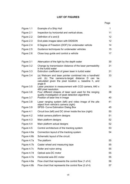
LIST OF FIGURESPageFigure 1.1 Example <strong>of</strong> a Ship Hull 1Figure 2.1 Inspection by horizontal and vertical slices. 11Figure 2.2 Definition <strong>of</strong> α and β 12Figure 2.3 End plate images taken with DIDSON 12Figure 2.4 6 Degree <strong>of</strong> Freedom (DOF) <strong>for</strong> underwater vehicle 14Figure 2.5 Guidance techniques <strong>for</strong> underwater vehicles 15Figure 2.6 Close loop guide and control a vehicle 17Figure 3.1 Attenuation <strong>of</strong> the light by the depth water 30Figure 3.2 Change by transmission distance <strong>of</strong> the laser permeability 31in the turbid waterFigure 3.3 Extinction coefficient <strong>of</strong> green laser in turbid water 31Figure 3.4 (a) Webcam and laser pointer combined into a handheld 33unit. (b) The camera-to-target distance D can becalculated given the pixel location u, baseline h, andangle θFigure 3.5 Laser precision in measurement with CCD camera, 640 x 34480 pixel resolution.Figure 3.6 Four different shapes <strong>of</strong> laser spot used <strong>for</strong> the ranging 38quality investigation <strong>of</strong> peak detection algorithmsFigure 3.7 Position <strong>of</strong> laser line in image 40Figure 3.8 Laser ranging <strong>system</strong> (left) and video image <strong>of</strong> the pile 41object from vehicle’s camera (right)Figure 3.9 SPSS- Curve Estimation Dialog Box 45Figure 4.1 Circuit box (left) and DC driver inside the box (right) 50Figure 4.2 Initial camera plat<strong>for</strong>m designs 51Figure 4.3 Main plat<strong>for</strong>m designs 52Figure 4.4 Main plat<strong>for</strong>m actual designs 52Figure 4.5 Control architecture <strong>of</strong> the tracking <strong>system</strong> 53Figure 4.6a Connection layout <strong>of</strong> the tracking <strong>system</strong> 54Figure 4.6bSchematic layout <strong>of</strong> the circuit.Figure 4.7a The plat<strong>for</strong>m 55Figure 4.7b Caster wheel and measuring tape 55Figure 4.7c Roller and nylon string 55Figure 4.7d Optical axis-DC motor 55Figure 4.7e Horizontal axis-DC motor 55Figure 4.8a Flow chart that represents the control flow (1 <strong>of</strong> 4) 56Figure 4.8b Flow chart that represents the control flow (2 <strong>of</strong> 4) 57viii


