The FEE Server Control Engine of the ALICE-TRD - Westfälische ...
The FEE Server Control Engine of the ALICE-TRD - Westfälische ...
The FEE Server Control Engine of the ALICE-TRD - Westfälische ...

Create successful ePaper yourself
Turn your PDF publications into a flip-book with our unique Google optimized e-Paper software.
4 <strong>The</strong> <strong>ALICE</strong> Transition Radiation Detector<br />
filter <strong>the</strong> data. Each MCM is capable to read out 18 pads every 100 ns. Second <strong>the</strong> MCMs<br />
calculate tracklets. A tracklet is a line which parameterizes <strong>the</strong> path <strong>of</strong> a particle through<br />
<strong>the</strong> chamber. <strong>The</strong> tracklet information are shipped to <strong>the</strong> GTU. <strong>The</strong> GTU uses <strong>the</strong> tracklet<br />
parameters to reconstruct <strong>the</strong> path <strong>of</strong> <strong>the</strong> particles inside <strong>the</strong> <strong>TRD</strong>. Based on <strong>the</strong> track<br />
information one can define various trigger conditions.<br />
One MCM contains two different chips (see figure 4.8). <strong>The</strong> first one is a pure analog<br />
chip with 18 shaping preamplifiers (PASA) and <strong>the</strong> second one (TRAP chip) contains<br />
ADCs and <strong>the</strong> complete digital part <strong>of</strong> <strong>the</strong> MCM. <strong>The</strong> chips are connected via chip-tochip<br />
bonding.<br />
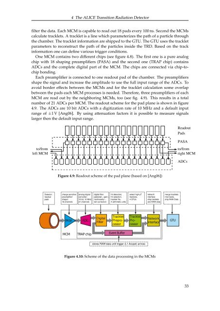
Each preamplifier is connected to one readout pad <strong>of</strong> <strong>the</strong> chamber. <strong>The</strong> preamplifiers<br />
shape <strong>the</strong> signal and increase <strong>the</strong> amplitude to use <strong>the</strong> full input range <strong>of</strong> <strong>the</strong> ADCs. To<br />
avoid border effects between <strong>the</strong> MCMs and for <strong>the</strong> tracklet calculation some overlap<br />
between <strong>the</strong> pads each MCM processes is needed. <strong>The</strong>refore, three preamplifiers <strong>of</strong> each<br />
MCM are read out by <strong>the</strong> neighboring MCMs, too (see fig. 4.9). This results in a total<br />
number <strong>of</strong> 21 ADCs per MCM. <strong>The</strong> readout scheme for <strong>the</strong> pad plane is shown in figure<br />
4.9. <strong>The</strong> ADCs are 10 bit ADCs with a digitization rate <strong>of</strong> 10 MHz and a default input<br />
range <strong>of</strong> ±1 V [Ang06]. By using attenuation factors it is possible to measure signals<br />
larger <strong>the</strong>n <strong>the</strong> default input range.<br />
to/from<br />
left MCM<br />
Detector:<br />
readout<br />
pads<br />
Figure 4.9: Readout scheme <strong>of</strong> <strong>the</strong> pad plane (based on [Ang06])<br />
charge sensitive<br />
preamplifier/<br />
shaper:<br />
18 channels<br />
<strong>TRD</strong> ADC<br />
PASA<br />
MCM<br />
analog digital<br />
converter:<br />
10 bit, 10 MHz<br />
21 channels<br />
TRAP chip<br />
digital filter:<br />
pedestal−, gain−,<br />
nonlinearity−,<br />
tail−correction<br />
Filter<br />
hit detection,<br />
hit selection,<br />
tracklet fits,<br />
4 arithmetic units<br />
cessor cessor<br />
Event Buffer<br />
select high pT<br />
tracklets,<br />
4 CPUs<br />
stores RAW data until trigger (L1 Accpet) arrives<br />
network<br />
interface:<br />
ship tracklets<br />
and RAW data<br />
Interface<br />
Figure 4.10: Scheme <strong>of</strong> <strong>the</strong> data processing in <strong>the</strong> MCMs<br />
merge tracklets<br />
into tracks,<br />
ship RAW Data<br />
GTU<br />
Readout<br />
Pads<br />
PASA<br />
to/from<br />
right MCM<br />
ADCs<br />
33