The FEE Server Control Engine of the ALICE-TRD - Westfälische ...
The FEE Server Control Engine of the ALICE-TRD - Westfälische ...
The FEE Server Control Engine of the ALICE-TRD - Westfälische ...

You also want an ePaper? Increase the reach of your titles
YUMPU automatically turns print PDFs into web optimized ePapers that Google loves.
5 <strong>The</strong> <strong>FEE</strong><strong>Server</strong> <strong>Control</strong> <strong>Engine</strong><br />
municate with <strong>the</strong> MCMs, power control routines, and a logging system. <strong>The</strong> trdCE contains<br />
all high level functions like a finite state machine, handling <strong>of</strong> incoming commands<br />
from <strong>the</strong> <strong>FEE</strong><strong>Server</strong> core, and classes for hardware tests. <strong>The</strong> main reason for splitting<br />
<strong>the</strong> control engine in two libraries is flexibility. On <strong>the</strong> DCS Board not only <strong>the</strong> <strong>FEE</strong><strong>Server</strong><br />
is installed. Many o<strong>the</strong>r tools are installed, too. <strong>The</strong>y are mainly used for debugging and<br />
testing. Nearly all <strong>of</strong> <strong>the</strong>se tools need hardware access but no complex control logic. By<br />
separating <strong>the</strong> basic functionality from <strong>the</strong> control logic, <strong>the</strong> tools can use <strong>the</strong> comfortable<br />
hardware interface provided by lib<strong>TRD</strong> without having to use <strong>the</strong> quite complex control<br />
logic in <strong>the</strong> trdCE.<br />
command execution thread<br />
Tests<br />
ORI system<br />
incomming<br />
Configuration<br />
Finite State<br />
Machine<br />
Configuration<br />
Handling<br />
Command<br />
execution<br />
SCSN Bus<br />
system<br />
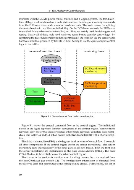
Figure 5.1: General control flow in <strong>the</strong> control engine<br />
monitoring thread<br />
DCS board sensors<br />
monitoring<br />
MCM temperature<br />
monitoring<br />
Figure 5.1 shows <strong>the</strong> general command flow in <strong>the</strong> control engine. <strong>The</strong> individual<br />
blocks in <strong>the</strong> figure represent different subsystems in <strong>the</strong> control engine. Some <strong>of</strong> <strong>the</strong>m<br />
represent only one or two classes whereas o<strong>the</strong>r blocks represent complete class hierarchies.<br />
<strong>The</strong> tables C.2 and C.1 list all classes in <strong>the</strong> trdCE and lib<strong>TRD</strong> with a short description.<br />
<strong>The</strong> finite state machine (FSM) is <strong>the</strong> highest level in terms <strong>of</strong> control flow. It controls<br />
all o<strong>the</strong>r components <strong>of</strong> <strong>the</strong> control engine except <strong>the</strong> sensor monitoring. <strong>The</strong> sensor<br />
monitoring runs independently <strong>of</strong> <strong>the</strong> o<strong>the</strong>r parts in its own thread. Both <strong>the</strong> FSM and<br />
<strong>the</strong> sensor monitoring are implemented in <strong>the</strong> class CEStateMachine (trdCE). <strong>The</strong> class<br />
CEStateMachine is <strong>the</strong> central class <strong>of</strong> <strong>the</strong> whole control engine.<br />
<strong>The</strong> classes in <strong>the</strong> section for configuration handling process <strong>the</strong> data received from<br />
<strong>the</strong> InterComLayer (see section 4.4). <strong>The</strong> configuration information is extracted from<br />
<strong>the</strong> received data and distributed to <strong>the</strong> corresponding classes. Fur<strong>the</strong>rmore, <strong>the</strong> list <strong>of</strong><br />
50