INSTALLATION MANUAL - Jergens Inc.
INSTALLATION MANUAL - Jergens Inc.
INSTALLATION MANUAL - Jergens Inc.

You also want an ePaper? Increase the reach of your titles
YUMPU automatically turns print PDFs into web optimized ePapers that Google loves.
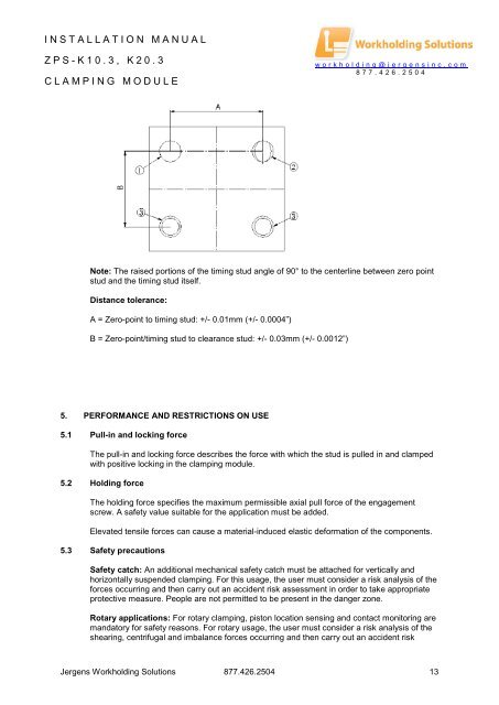
<strong>INSTALLATION</strong> <strong>MANUAL</strong>ZPS- K 10.3, K20.3CLAMPING MODULEworkholding@jergensinc.com877.426.2504Note: The raised portions of the timing stud angle of 90° to the centerline between zero pointstud and the timing stud itself.Distance tolerance:A = Zero-point to timing stud: +/- 0.01mm (+/- 0.0004”)B = Zero-point/timing stud to clearance stud: +/- 0.03mm (+/- 0.0012”)5. PERFORMANCE AND RESTRICTIONS ON USE5.1 Pull-in and locking forceThe pull-in and locking force describes the force with which the stud is pulled in and clampedwith positive locking in the clamping module.5.2 Holding forceThe holding force specifies the maximum permissible axial pull force of the engagementscrew. A safety value suitable for the application must be added.Elevated tensile forces can cause a material-induced elastic deformation of the components.5.3 Safety precautionsSafety catch: An additional mechanical safety catch must be attached for vertically andhorizontally suspended clamping. For this usage, the user must consider a risk analysis of theforces occurring and then carry out an accident risk assessment in order to take appropriateprotective measure. People are not permitted to be present in the danger zone.Rotary applications: For rotary clamping, piston location sensing and contact monitoring aremandatory for safety reasons. For rotary usage, the user must consider a risk analysis of theshearing, centrifugal and imbalance forces occurring and then carry out an accident risk<strong>Jergens</strong> Workholding Solutions 877.426.2504 13