INSTALLATION MANUAL - Jergens Inc.
INSTALLATION MANUAL - Jergens Inc.
INSTALLATION MANUAL - Jergens Inc.

Create successful ePaper yourself
Turn your PDF publications into a flip-book with our unique Google optimized e-Paper software.
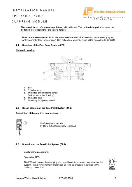
<strong>INSTALLATION</strong> <strong>MANUAL</strong>ZPS- K 10.3, K20.3CLAMPING MODULEworkholding@jergensinc.com877.426.2504The lateral force refers to zero point and slit pull stud. The undersized pull stud must notbe taken into account for the lateral forces.Note on the compressed air in the pneumatic version: Prepared with service unit, (dry air,water separator filter, vapour oiler). Use only oils of viscosity class VG32 according to ISO34482.1 Structure of the Zero Point System (ZPS)Hydraulic version1. Ball2. Cylinder screw3. Threaded pin as forcing screw(Not shown in the drawing)4. Threaded stud5. Assembly tool pre-mounted2.2 Circuit diagram of the Zero Point System (ZPS)Description of the required connections:1 = Open pneumatically3 = Blow-out pneumatically (optional)32.3 Operation of the Zero Point System (ZPS)Unclamping procedure:Pressurize ZPS.The ZPS will release the clamping stud, enabling it to be moved in and out of thesystem. The ZPS will remain unclamped as long as pressure is applied to theunclamp connection.<strong>Jergens</strong> Workholding Solutions 877.426.2504 7