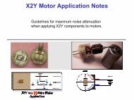
RF Filtering for Audio Amplifier Circuits
RF Filtering for Audio Amplifier Circuits
RF Filtering for Audio Amplifier Circuits

You also want an ePaper? Increase the reach of your titles
YUMPU automatically turns print PDFs into web optimized ePapers that Google loves.
<strong>RF</strong> <strong>Filtering</strong> <strong>for</strong> <strong>Audio</strong> <strong>Amplifier</strong> <strong>Circuits</strong>Is the DC Resistance of Your <strong>RF</strong> Filter Affecting TheOverall Power Output of Your <strong>Audio</strong> <strong>Amplifier</strong>?IntroductionToday, as more EMC regulations are imposed by governments, or selfimposedby industry, the need <strong>for</strong> cost effective filtering <strong>for</strong> audio amplifiercircuits is more important than ever. <strong>Audio</strong> amplifiers are used ineverything from car and home stereos to portable CD devices and MP3players. Any device that outputs sound to a speaker requires an audioamplifier and their use has increased dramatically along with the growingnumbers of consumer electronic devices.Changes in the electromagnetic interference (EMI) filter technologymanufactured by the passive component industry, combined withpressures to keep consumer electronics low cost, have altered the waythat audio amplifier circuits are filtered. What may have been overlookedas these changes occurred was the DC resistance added to the circuit asdesigners moved from a standard through-hole type ceramic capacitor tothe multilayer chip capacitor (MLCC) feedthru device. Prohibitive costs <strong>for</strong>the through-hole type capacitors and the frequency limitations of standardMLCC capacitors used <strong>for</strong> bypassing have <strong>for</strong>ced engineers to use thenewer chip feedthru components to bridge the price/per<strong>for</strong>mance gap.This application note will show how to use a single MLCC component withadvanced X2Y® Technology in bypass to improve audio amplifier outputper<strong>for</strong>mance by removing the DC resistance (and resulting voltage drop) inthe circuit and to lower overall system cost <strong>for</strong> EMI filtering.Past Filter Methods <strong>for</strong> Car <strong>Audio</strong>In the past, many in the automotive industry used ceramic through-holecapacitors to filter the audio amplifier in car radios. These popular devicesprovided high insertion loss with no effect on the power output of the audioamplifier because wire was fed through a hole in the center of the device,which was mounted to a grounded plate (Fig 1). As DC current travelingthrough the wire passed through the filter device, EMI (<strong>RF</strong>) noise wasshunted to a circuit ground reference.Application Note11192001-2-1
SchematicFig 1. Standard “through-hole” capacitorsConsumer and OEM (Original Equipment Manufacturer) price pressuresthen <strong>for</strong>ced the car audio industry to look to alternative, more cost effectivemethods to filter the same application.One popular solution that has emerged is the chip feedthru capacitor.Although both capacitors are called “feedthru”, the method by whichcurrent is fed through the two devices differs dramatically. The chipfeedthru stacks electrode plates internally and the DC current is fedthrough the component electrodes and the EMI noise is shunted to aground reference (Fig 2). The device must carry the DC current of thecircuit and shunt <strong>RF</strong> current to ground.SchematicFig 2. Chip “feedthru” capacitors give resistance to the DC current in acircuitApplication Note11192001-2-1
Costs are reduced in many ways. Component cost is lower. There is noneed <strong>for</strong> a mounting plate <strong>for</strong> the multilayer chip feedthru, which can besurface mounted on the PC board. Labor costs are lowered through theuse of automated pick and place machines during production. At asubstantial systems savings over its predecessor, the MLCC feedthruseems a natural replacement.DC ResistanceWhen current is fed through a chip feedthru device, there is a DCresistance associated with the component that reduces the amount ofpower output that was intended from the audio amplifier. This is not justtrue <strong>for</strong> a chip feedthru capacitor, but it is also true <strong>for</strong> any filter componentthat offers DC resistance to the circuit.The DC resistance of a typical ceramic chip feedthru is approximately < 0.6Ω <strong>for</strong> 0805 to 1206 and ” Ω <strong>for</strong> a 1608 size chip ferrite bead device(both rated <strong>for</strong> 300mA current). The Power Formula in Fig 3 describes therelationship of power to resistance. As DC current travels through theresistance of the filter component, power is dissipated that is otherwiseintended <strong>for</strong> the circuit, as shown in the examples (Fig 4)Example: Power FormulaBridged-output amplifier Pd max Equation(National Semiconductor LM4862 Boomer)Pd max = 4(V dd ) 2 / 2π 2 R L = 2(V dd ) 2 / π 2 R LFig 3.Power EquationExample 1): <strong>Amplifier</strong> Without Filter DC ResistanceLM 4862:Vdd = 3V, R L = 8ΩPd max = 4(V dd ) 2 / 2π 2 R L = 4(3) 2 / 2π 2 (8 Ω) = 228mWExample 2): <strong>Audio</strong> <strong>Amplifier</strong> And Filter With DC ResistanceLM 4862:Vdd = 3V, R filter = Typical 0.4Ω per filterR L ′ = R L +R filter = 8Ω + (0.4Ω + 0.4Ω) = 8.8ΩPd max = 4(V dd ) 2 / 2π 2 R L ′ = 4(3) 2 / 2π 2 (8.8Ω) = 207.2mWFig 4. Examples ComparisonsApplication Note11192001-2-1
Note: Adding a 0.4Ω DC filter resistance per side (Fig 5) will cause a lossof output power. 228mW -207.2mW = 20.8mW (9.12% loss of outputpower).-Feed Thru Chip(Typ. DC = 0.4Ω)+R L = 8 Ω-Av = -1Feed Thru Chip(Typ. DC = 0.4Ω)+V ddFig 5. Example circuit showing feedthru capacitors.Overall circuit power loss can be significant when multiple resistive devicesare used throughout a design. After calculating the reduced power outputof the amp because of the higher load impedance, you can then calculatethe % of output power loss to the speaker:Speaker Output power = (Speaker Resistance/ Total Resistance) x TotalOutput Power = (8/8.8) x 207.2mW = 188.36mW% of Power loss to Speaker = [1-(Speaker output Power with filter / TotalOutput Power without filter)} x 100 = (188.36mW / 228mW) x 100 = 17.5 %loss of power to speakerAnother factor affected by the DC resistance is damping of theloudspeaker, which affects the sound quality of the bass.Damping Factor is calculated by the following <strong>for</strong>mula:Damping = ( R ls + R out )/R outR ls = loudspeaker resistance,R out = amplifier output resistance/impedance.Application Note11192001-2-1
<strong>Audio</strong> enthusiasts are often tuned to the sound quality associated withbass. When resistance is added to the R out , it decreases the dampingfactor. A high series resistance and hence a low damping factor will give a‘boomy’ bass, in contrast with a "tense" sounding bass <strong>for</strong> a high dampingfactor.X2Y Bypass FilterWhen using an X2Y bypass device there is no new DC resistance addedto the circuit over the trace or wire resistance. A single component isplaced in bypass between the two lines and the two center groundterminations of the component are attached to the circuit ground reference,offering no DC resistance or power loss to the amplifier circuit (Fig 6).X2YFig 6. The X2Y bypass capacitor gives no DC resistance and is lowimpedance to <strong>RF</strong> noise.-+X2Y• •R L = 8 Ω-Av = -1+V ddFig 7. Example circuit showing X2Y Bypass capacitors.Example 3) <strong>Amplifier</strong> with X2Y FilterSince the X2Y chip filter is in bypass (Fig 6,7), the DC resistance in thecircuit is 0. Hence the bridged-output amplifier power is the same as theexample shown earlier without a filter in the circuit.Pd max = 4(V dd ) 2 / 2π 2 R L = 4(3) 2 / 2π 2 (8 Ω) = 228mWApplication Note11192001-2-1
Other advantages to using a single X2Y as opposed to two or more chipfeedthru caps are:qqqqOne X2Y is needed versus two or more resistive devices, dependingon the applicationBetter balance, ” FDSDFLWDQFH WROHUDQFH EHWZHHQ HDFK LQWHUQDOline to ground YEqual aging and temperature tracking because of the singlecomponent package.Broader Insertion Loss Characteristics with X2YPortable <strong>Audio</strong> DevicesIn consumer electronic devices, where smaller, better, cheaper is desired,chip feedthru devices are used extensively. A typical MP3 portable musicdevice may use as many as 10 devices <strong>for</strong> filtering the different internalcomponents such as audio amplifiers, ASIC devices, digital to analogsignal converters, etc. (Fig 8).HeadphonesJACKRGndL<strong>Audio</strong><strong>Amplifier</strong>Digital toAnalogConverterICMemoryStickDevice MemoryFig 8.Typical MP 3 player, source Murata Manufacturing C0.,LtdStereo headphone jacks are another ideal application <strong>for</strong> X2Y bypass filterdevices. Standard components would require one component per line (Fig9). Although there is a new device available to filter all three lines at once,it adds series resistance to the circuit.Application Note11192001-2-1
Right SpeakerGNDLeft SpeakerorRight SpeakerGNDLeft SpeakerFig 9. Standard components with DC resistanceA single X2Y component can be used in the same application by placingthe end terminations of the X2Y device on the right and left speakers andthe center ground terminations of the component are placed on the groundof the jack (Fig 10).Right SpeakerA+GNDLeft SpeakerG2BG1-Right InputSpeakerA+To GNDG2Left OutputSpeakerFig 10. Example placements of an X2Y bypass capacitorBG1-For mounting X2Y components, use a single continuous mounting padunder the G1 and G2 terminations and a minimum of two vias to ensure aparallel connection to the board plane (Fig 11). Proper grounding andattachment of X2Y is shown in the application note at this link: Grounding.Land PatternsPerspectives of mounted componentTUVABBoard SurfaceGround Pl aneViaViaViaYWAViaG1X2YG2ViaBSide ViewABoard SurfaceGround Pl aneZFront ViewFigure 10. Pad and via layoutApplication Note11192001-2-1
The chart in Fig 11 below compares the different attributes of someselected components.Filter DevicesEIASizeDC RatedCurrentDCResistancePerLine/DeviceCircuitPowerLoss ?DevicesRequiredCostO603-2220Bypass,No LimitNone None One Low/MediumO805Feedthru,300mAYes,0.6 OhmsYesMono two,Stereo threeLow/Medium1206 Feedthru,300mAYes,0.6 OhmsYesMono two,Stereo threeLow/Medium1806Feedthru,2AYes,0.04 OhmsYesMono two,Stereo threeMedium2220Feedthru,6AYes,0.01 OhmsYesMono two,Stereo threeHigh2506Feedthru,2AYes,0.04 OhmsYesMono two,Stereo threeHigh1206Feedthru,6AYes,0.01 OhmsYesMono two,Stereo threeHigh1206Feedthru,100mAYes,0.40 OhmsYes One HighFig 11. Comparison ChartConclusionUsing the X2Y bypass capacitor <strong>for</strong> filtering audio amplifiers will result inno power loss because of DC resistance. Power loss is inherent in thedesign of series feedthru chip components and can degrade circuitper<strong>for</strong>mance. X2Y will function equally well in amplifier circuits where thespeakers are fed power differentially. These and other circuits will beshown in future versions of this application note and posted periodically inthe resource library section of the X2Y website.Application Note11192001-2-1
Application Note Contributors:James P. Muccioli, X2Y Attenuators,LLCDavid J. Anthony, X2Y Attenuators,LLCAnthony A. Anthony, X2Y Attenuators,LLCBart Bouma, Phycomp The Netherlands B.V.More in<strong>for</strong>mation about X2Y-capacitors can be accessed at this link:Phycomp ComponentsSubject Line: X2Y Application Note CommentsIn<strong>for</strong>mation and suggestions furnished in this and other documents by X2Y Attenuators, LLC. isbelieved to be reliable and accurate. X2Y Attenuators, LLC assumes no responsibility <strong>for</strong> its use.X2Y® is a registered name. All other brand or product names mentioned in this document aretrademark or registered trademarks of their respective holders. These notes are subject tochange without notice.Application Note11192001-2-1