High Voltage 05, 5G and REDLE K-S Series - Lemo
High Voltage 05, 5G and REDLE K-S Series - Lemo
High Voltage 05, 5G and REDLE K-S Series - Lemo

Create successful ePaper yourself
Turn your PDF publications into a flip-book with our unique Google optimized e-Paper software.
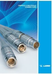
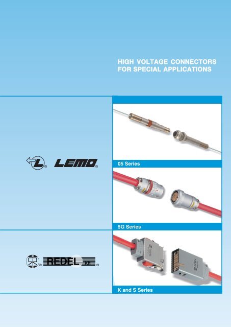
HIGH VOLTAGE CONNECTORSFOR SPECIAL APPLICATIONS®®<strong>05</strong> <strong>Series</strong><strong>5G</strong> <strong>Series</strong>®REDEL Kft ®K <strong>and</strong> S <strong>Series</strong>
No reproduction or use without express permission of editorial or pictorial content, in any manner.LEMO reserve the right at all times to modify <strong>and</strong> improve specifications without any notification.
® ®<strong>05</strong> <strong>Series</strong> Connectors<strong>High</strong> voltage connectors of the new <strong>05</strong> miniature serieshave been specifically developed to meet the requirementsof experimental nuclear research programme.The <strong>05</strong> series contains a miniature HV 12kV d.c. (testvoltage) contacts. This crimp contact is removable fromthe shell <strong>and</strong> is inserted in a PEEK insulator.The actual mating is provided by the LEMO Push-Pullsystem, renowned for its reliability worldwide <strong>and</strong> a redsafety nut to secure the connection.The compact design of these connectors makes themideal for applications where minimal mass <strong>and</strong> spacesaving are critical factors.InterconnectionsStraight plugFixed socketFFRPESLEMO’s Push-Pull Self-Latching Connecting SystemThis self-latching system is renowned worldwide for its easy <strong>and</strong> quick mating <strong>and</strong> unmating features. It provides absolutesecurity against vibration, shock or pull on the cable, <strong>and</strong> facilitates operation in a very limited space.The LEMO self-latching system allows the connectorto be mated by simply pushing the plug axially into thesocket.Once firmly latched, connection cannot be broken bypulling on the cable or any other component part otherthan the outer release sleeve.When required, the connector is disengaged by asingle axial pull on the outer release sleeve. This firstdisengages the latches <strong>and</strong> then withdraws the plugfrom the socket.For added security a safety nut (shown in red) canprevent disengagement by blocking the motion of theouter release sleeve.1
® ®Part Section Showing Internal ComponentsConnector1234567Fixed socketshellcrimp back endhexagonal nutconical nutinsulatorHV female contactcrimp ferrule7 2 1 5 6 3 48 6 5 1 3 2 4 712345678Straight plugouter shelllatch sleevesafety nutcrimp back endinsulatorHV male contactcrimp ferruleearthing crownHV ContactMale contact2 3 1 41 32Female contact1234male contactinsulatorclipssealing gl<strong>and</strong>123female contactinsulatorclipsTechnical characteristicsMechanical <strong>and</strong> climaticalElectrical characteristicsCharacteristicValueSt<strong>and</strong>ardCharacteristic Value St<strong>and</strong>ardContact retention forceWorking temperatureMechanical lifeClimatic classRadiation resistance40 N IEC 6<strong>05</strong>12-8 test 15a-20 °C to +125°C> 200 cycles IEC 6<strong>05</strong>12-5 test 9a20/125/21 IEC 60068-1> 10 6 GyTest voltage d.c. 1)Rated currentContact resistanceScreen resistanceInsulation resistance12 kV (1 min.) IEC 6<strong>05</strong>12-2 test 4a4 A IEC 6<strong>05</strong>12-3 test 5a≤ 8 mΩ IEC 6<strong>05</strong>12-2 test 2a≤150 mΩ IEC 6<strong>05</strong>12-2 test 2f≥ 10 12 Ω IEC 6<strong>05</strong>12-2 test 3aNote:1) specific assembly instructions shall be respected. (see page 6 <strong>and</strong> 7)Materials <strong>and</strong> Treatment – ConnectorContactComponentOutershell + crimpendSafety nutEarthing crownLatch sleeveHex <strong>and</strong> conical nutInsulatorCrimp ferruleSurface treatmentMaterial (st<strong>and</strong>ard)(µm)NiAluminium (AA 6012) 5Aluminium (AA 6012) Anodized redAluminium special 5Aluminium special 5Aluminium (AA 6012) Anodized naturalPEEK –Aluminium (AA 6012) 5ComponentMale contactFemale contactContact clipsInsulatorSealing gl<strong>and</strong>Surface treatmentMaterial (st<strong>and</strong>ard)(µm)Cu Ni AuBrass (UNS C38500) 0.5 3 1.0Bronze (UNS C54400) 0.5 3 1.5Cu-Be (QQ-C-530) –PEEK –Silicone PVMQ –2
® ®ModelsFFRStraight plug for cable crimping,with safety nutPart NumberCablegroup29.842FFR.<strong>05</strong>.403.LLAE141FFR.<strong>05</strong>.403.LLAE14212ø 6PESFixed socket, with two nuts, for cable crimping42S 5.7S 82.5Part NumberPES.<strong>05</strong>.403.LLLE141PES.<strong>05</strong>.403.LLLE142Cablegroup12M6.5x0.6ø 8.5ø 9.28.5 max.S 7Recomm<strong>and</strong>ed high voltage cablesCable groupManufacturerPart NumberCERN TypeConstruction <strong>and</strong> dimensionsConductor Dielectric Screen SheathConstr. Mat. ø Mat. ø Mat. Mat. øCoronascreen1ABBNK - 45/94HTC 50-1-1CuSn Polyolefine7x0.17 CuSn 0.51 PE solid 1.516x4x0.13.3yes2HABIA31789-004-001HFI 150 mini coax Mono Cu 0.16 HFI150 0.5Drain 2x0.1+ HFI150 1.15Alu polyesterno3
® ®AccessoriesFFA-ERA <strong>High</strong> <strong>Voltage</strong> ContactsContact Part NumberMale contact Female contactCablegroupL(mm)LmaleFFA.<strong>05</strong>.403.ZLA1FFA.<strong>05</strong>.403.ZLA2ERA.<strong>05</strong>.403.ZLL1ERA.<strong>05</strong>.403.ZLL21246femaleGMA Heatshrink tubeShall be ordered separatelyLø D min.Part numberGMA.30.010.STGMA.15.010.STCablegroup1+22NameSupplierProduct referenceRAYCHEM ® RNF 3000 3/1RAYCHEM ® RNF 3000 1.5/0.5øD L(mm) (mm)3.0 131.5 9Note: for cable group 2, the two heatshrink tubes are necessary● Material: Polyolefin transparent10FFS Crimp ferruleModel 1ø 4.1Part numberCablegroupModel10FFS.<strong>05</strong>.160.PMFFS.<strong>05</strong>.161.PM1212Model 2ø 1.4● Material: Aluminium alloy (AA6012) nickel plated7M 6.5 x 0.6 2.<strong>5G</strong>EC Conical nutPart numberø 8.<strong>5G</strong>EC.<strong>05</strong>.241.PT● Material: Aluminium alloy (AA 6012) natural anodized.8M 6.5 x 0.6 2GEA Hexagonal nutsPart number9.2GEA.<strong>05</strong>.241.PT● Material: Aluminium alloy (AA 6012) natural anodized.4
® ®Tooling37DCH Spanner for conical nut39.7Part NumberDCH.91.113.9TNø 11● Material: Blackened steel.DCFExtraction tools for HV contactsPart NumberAutomatic modelDCF.91.133.5LTDPHCrimping tool with die <strong>and</strong> positionerPart NumberApplicationsCablegroupMarking on dieDPH.99.0<strong>05</strong>.2KDPH.99.060.11KDPH.99.065.11Kshieldcentre contactcentre contact1-212DPH.91.0<strong>05</strong>.2KDPH.91.001.16KDPK.91.001.16KDPNDies <strong>and</strong> positionerPart NumberApplicationsCablegroupMarking on dieDPN.99.0<strong>05</strong>.2KDPN.99.060.11KDPN.99.065.11Kshieldcentre contactcentre contact1-212DPH.91.0<strong>05</strong>.2KDPH.91.001.16KDPK.91.001.16K● Dies material: Blackened steelPanel cut-out10 min.ø 6.6+ 0.1<strong>05</strong>.8+ 0.10Recommended mounting nut torque: 0.8 Nm.5
® ®Termination Instructions Cable Group 1534FFR1534PES9 ±0.2 3.5 ±0.21. Strip the cable according to the given dimensions,remove carefully the cable corona screen, making surethat the cable dielectric is not damaged. Remove alsothe aluminium foil <strong>and</strong> the textile tape.Clean the dielectric with isopropylic alcool.Dimensions in mm.334443 ±0.2 1Apply laquerCrimpAApply laquer3112. Place the crimp ferrule ➀ on the cable. Widen completelythe shield braid <strong>and</strong> fold it back over the jacket.Introduce the cable center conductor into the HVcontact ➃ until the contact end rests against the dielectric<strong>and</strong> the conductor is visible through the contact inspectionhole. Crimp with the LEMO crimping toolDPH.99.060.11K. Cover the crimp section of thecontact <strong>and</strong> the Peek end of the HV contact with a layerof insulating laquer. Let the laquer dry, approx.15 min.Note: We recomm<strong>and</strong> the laquer Urethanref: Cellpack n° 9121103. Slide the heatshrink tube ➂ over the HV contact until itrests against the contact insulator.One end of the heatshrink tube shall be located at theposition A of the HV contact insulator. Shrink the tube.ShrinkA4 3Shrink514. Fully introduce the HV contact into the connector shell➄. Check that the contact is correctly located <strong>and</strong>remains in position when given a gentle pull. Place thecable shield braid str<strong>and</strong> over the shell crimp back end,cut the length of braid in excess.5155. Slide the crimp ferrule over the cable shield until itrests against the connector shell. Crimp with theLEMO crimping tool DPH.99.0<strong>05</strong>.2K.5CrimpCrimp6
® ®Termination Instructions Cable Group 2534 2FFR1534 2PES14 ±0.210 ±0.23 ±0.221. Strip the cable according to the given dimensions, cutthe aluminium foil making sure that the dielectric is notdamaged. Do not damage the 2 drain wires.Fold the drain wires back over the outer jacket <strong>and</strong>slide over the small heatshrink tube ➁.Clean the dielectric with isopropylic alcool.Dimensions in mm.Apply laquer3 42 1AApply laquerBCrimp3 4 2 1Shrink4 3 Shrink 1A4 3 12. Place the crimp ferrule ➀ introducing first the small diameteron the cable. Introduce the cable centerconductor <strong>and</strong> a part of the dielectric into the HVcontact ➃ until the conductor is fully visible through thecontact inspection hole. Crimp with the LEMO crimpingtool DPH.99.065.11K. Cover the crimp section of thecontact <strong>and</strong> a short length of the dielectric with a layerof insulating laquer. Let the laquer dry, approx. 15 min.Note: We recomm<strong>and</strong> the laquer Urethanref: Cellpack n° 912110Slide the heatskrink tube ➁ over the HV contact until itrests against the contact insulator at the position B.Shrink the tube. Cover the Peek end of the HV contact<strong>and</strong> the first heatshrink tube with a layer of the insulatinglaquer. Let the laquer dry, approx. 15 min.3. Slide the heatshrink tube ➂ over the HV contact until itrests against the contact insulator.One end of the heatshrink tube shall be located at theposition A of the HV contact insulator. Shrink the tube.Shrink543 14. Fully introduce the HV contact into the connector shell➄. Check that the contact is correctly located <strong>and</strong>remains in position when given a gentle pull. Place the 2drain wire around the shell crimp back end.5A4 3 155. Slide the crimp ferrule over the cable shield until itrests against the connector shell. Crimp with theLEMO crimping tool DPH.99.0<strong>05</strong>.2K.5CrimpCrimp7
® ®<strong>5G</strong> <strong>Series</strong> Connectors<strong>High</strong> voltage cylindrical connectors of the new <strong>5G</strong> serieshave been specifically developed to meet the requirementsof the “ATLAS” experimental nuclear research programmeat the CERN.The <strong>5G</strong> series contains 50 miniature HV 12kV d.c. (testvoltage) contacts. These crimp contacts are removablefrom the shell <strong>and</strong> are inserted in a PEEK insulator. Thesame HV contacts are used in the <strong>05</strong> series.The actual mating is provided by the LEMO Push-Pullsystem, renowned for its reliability worldwide <strong>and</strong> a redsafety nut to secure the connection.Two keying alternative (code R or W) are available.The compact design of these connectors makes themideal for applications where minimal mass <strong>and</strong> spacesaving are critical factors.InterconnectionsStraight plugFixed socketDANGERDANGERFGPHLEMO’s Push-Pull Self-Latching Connecting SystemThis self-latching system is renowned worldwide for its easy <strong>and</strong> quick mating <strong>and</strong> unmating features. It provides absolutesecurity against vibration, shock or pull on the cable, <strong>and</strong> facilitates operation in a very limited space.DANGERDANGERThe LEMO self-latching system allows the connectorto be mated by simply pushing the plug axially into thesocket.Once firmly latched, connection cannot be broken bypulling on the cable or any other component part otherthan the outer release sleeve.When required, the connector is disengaged by asingle axial pull on the outer release sleeve. This firstdisengages the latches <strong>and</strong> then withdraws the plugfrom the socket.For added security a safety nut (shown in red) canprevent disengagement by blocking the motion of theouter release sleeve.8
® ®Part Section Showing Internal ComponentsConnector7 8 4 1 2 3 5 6 10 98 2 7 1 3 4 6 5DANGERDANGERFixed socketStraight plug12345outer shellearthing crownretaining ringclamp collet nutround nut678910conical nutadapter w. cable colletkeyed mid-pieceinsulatorHV male contact1234outer shelllatch sleevesafety nutclamp collet nut5678adapter w. cable colletkeyed mid-pieceinsulatorHV female contactHV ContactMale contact2 3 1 41 32Female contact1234male contactinsulatorclipssealing gl<strong>and</strong>123female contactinsulatorclipsTechnical characteristicsMechanical <strong>and</strong> climaticalElectrical characteristicsCharacteristicValueSt<strong>and</strong>ardCharacteristic Value St<strong>and</strong>ardContact retention forceWorking temperatureMechanical lifeClimatic classRadiation resistance40 N IEC 6<strong>05</strong>12-8 test 15a-20 °C to +125°C> 100 cycles IEC 6<strong>05</strong>12-5 test 9a20/125/21 IEC 60068-1>10 6 GyTest voltage d.c. 1)Rated currentContact resistanceScreen resistanceInsulation resistance12 kV (1 min.) IEC 6<strong>05</strong>12-2 test 4a4 A IEC 6<strong>05</strong>12-3 test 5a≤ 8 mΩ IEC 6<strong>05</strong>12-2 test 2a≤150 mΩ IEC 6<strong>05</strong>12-2 test 2f≥ 10 12 Ω IEC 6<strong>05</strong>12-2 test 3aNote: 1) specific assembly instructions shall be respected.Materials <strong>and</strong> Treatment – ConnectorContactComponentOutershell + collet nutSafety nutEarthing crownLatch sleeveRound <strong>and</strong> conical nutInsulatorOther metallic piecesMaterial (st<strong>and</strong>ard)Aluminium (AA 6012)Aluminium (AA 6012)Surface treatment(µm)NiAnodized naturalAnodized redAluminium special 5Aluminium special 5Aluminium (AA 6012) Anodized naturalPEEK –AluminiumAnodized naturalComponentMale contactFemale contactContact clipsInsulatorSealing gl<strong>and</strong>Surface treatmentMaterial (st<strong>and</strong>ard)(µm)Cu Ni AuBrass (UNS C38500) 0.5 3 1.0Bronze (UNS C54400) 0.5 3 1.5Cu-Be (QQ-C-530) –PEEK –Silicone PVMQ –9
® ®Alignment key <strong>and</strong> polarized keying systemαβRef.DotColourAngleα β γ δPlugHV contact typeSocketγδ●●Ryellow110° 1<strong>05</strong>° 25° 35°malefemaleFront view of a socket●●Wred95° 115° 20° 30°femalemaleModelsFG●Straight plug with keys (code R or W),cable clamp-collet <strong>and</strong> safety nut67Part NumberCable GroupCable ø14.0 min.16.5 max.DANGER52ø 35FGR.<strong>5G</strong>.450.LLAY5T1FGR.<strong>5G</strong>.450.LLAY5T2FGW.<strong>5G</strong>.450.LLLY5T1FGW.<strong>5G</strong>.450.LLLY5T21212S 30S 31PH●Fixed socket with keys (code R or W),cable clamp-collet, 2 nuts fixing(back panel mounting)~64.7S 37Part NumberCable Groupø 35Cable ø14.0 min.16.5 max.DANGER5 max.5ø 41PHR.<strong>5G</strong>.450.LLLY5T1PHR.<strong>5G</strong>.450.LLLY5T2PHW.<strong>5G</strong>.450.LLAY5T1PHW.<strong>5G</strong>.450.LLAY5T21212S 30S 31S 33.5Recomm<strong>and</strong>ed high voltage cablesCable groupManufacturerPart NumberCERN TypeType/Nb. ofconductorConstruction <strong>and</strong> dimensionsConductor Dielectric Screen SheathConstr. Mat. ø Mat. ø Mat. Mat. øCoronascreen1SILISOLCEPMB -56x0.12 mm 2Multi/56CuSn7x0.15 CuSn 0.45 PE 1.5+ AluSilic 14.5no1ABBNK - 45/94HTC 50-1-1Mono/17x0.17 CuSn 0.51 PE solid 1.5CuSn Polyolefine3.316x4x0.1yes2HABIA31789-004-001HFI 150 minicoaxMono/1Drain 2x0.1Mono Cu 0.16 HFI150 0.5 + HFI150 1.15 noAlu polyester10
® ®AccessoriesFFA-ERA HV ContactsContact Part NumberMale contact Female contactCablegroupL(mm)LmaleFFA.<strong>05</strong>.403.ZLA1FFA.<strong>05</strong>.403.ZLA2ERA.<strong>05</strong>.403.ZLL1ERA.<strong>05</strong>.403.ZLL21246femaleGMA Heatshrink tubeShall be ordered separatelyLø D min.Part numberGMA.30.010.STGMA.15.010.STCablegroup1+22NameSupplierProduct referenceRAYCHEM ® RNF 3000 3/1RAYCHEM ® RNF 3000 1.5/0.5øD L(mm) (mm)3.0 131.5 9Note: for cable group 2, the two heatshrink tubes are necessary● Material: Polyolefin transparent37M 35 x 1<strong>5G</strong>EC Conical nutPart numberø 41GEC.<strong>5G</strong>.240.PT● Material: Aluminium alloy (AA6012) natural anodizedø 40M 35 x 18GEB Round nutPart numberGEB.<strong>5G</strong>.240.PT● Material: Aluminium alloy (AA6012) natural anodizedFGG Extension piece36Part Numberø 27.9ø 29FGG.<strong>5G</strong>.815.PNNote: allows an extension of the plug or the socket to make cable stripping<strong>and</strong> mounting easier when weight <strong>and</strong> size are not critical● Material: Aluminium alloy (AA6012) natural anodized11
® ®Tooling90DCH Spanner for conical nut81.5Part NumberDCH.91.418.0TNø 45● Material: Blackened steel.54DCPSet of flat spanners for collet nuts <strong>and</strong> round nuts31.130.13.5Part NumberDCP.91.0<strong>05</strong>.TN160● Material: Blackened steel.DCFExtraction tools for HV contactsPart NumberAutomatic modelDCF.91.133.5LTDPHCrimping tool with die <strong>and</strong> positionerPart NumberApplicationsCablegroupMarking on dieDPH.99.0<strong>05</strong>.2KDPH.99.060.11KDPH.99.065.11Kshieldcentre contactcentre contact1-212DPH.91.0<strong>05</strong>.2KDPH.91.001.16KDPK.91.001.16KNote: DPN Dies <strong>and</strong> positioner: See <strong>05</strong> series data sheet.Panel cut-out42 min.ø 35.2 + 0.1033.5+ 0.10Recommended mounting nut torque: 7 Nm.12
® ®Termination Instructions Cable Group 1 (multi HT cable)7534FG•617534PH•2245001. Strip the cable according to the given dimensions.A 500 mm length is necessary to give enough flexibilityto the cable.Remove first the outer jacket <strong>and</strong> the screen then thedielectric of each individual high-voltage conductor,making sure that the cable dielectric is not damaged.3.5 ±0.2 1Dimensions in mm.55552. Slide 2 pieces of 55mm heat-shrink tubing, (not supplied)of the correct size, the clamp collet nut ➀ <strong>and</strong>the adapter with cable collet ➁ on the cable.23344AApply laquerCrimpCrimp3. For each individual high-voltage conductor install aHV contact as follow:3.1 Introduce the cable center conductor into the HVcontact ➃ until the conductor end rests against thedielectric <strong>and</strong> the conductor is visible through thecontact inspection hole. Crimp with the LEMO crimpingtool DPH.99.060.11K. Cover the crimp section ofthe contact <strong>and</strong> the Peek end of the HV contact witha layer of insulating laquer. Let the laquer dry,approx. 15 min.Note: We recomm<strong>and</strong> the laquer Urethanref: Cellpack n° 912110Apply laquer43Shrink3.2 Slide the heatshrink tube ➂ over the HV contact untilit rests against the contact insulator.One end of the heatshrink tube shall be located at theposition A of the HV contact insulator. Shrink thetube.A43Shrink13
® ®554. Fully introduce the HV contacts into the insulator ➄.– The short insulator shall be fitted with the femaleHV contacts.– The long insulator shall be fitted with the maleHV contacts.Check that the contacts are correctly located <strong>and</strong>remains in position when given a gentle pull.soldersolder6ground wire L = 130 mmground wire L = 130 mm5. Install a ground wire (not supplied) as follow:5.1 Wrap a tin copper wire 0.5 mm 2 over a 6 mm lengthof the cable screen <strong>and</strong> hold the ground wire asshown. Then solder.Solder an earthing washer with a 3.5 mm hole on theother side.625ShrinkShrink5.2 Cover the end of the cable screen with the first heatshrinktube <strong>and</strong> the end of the cable jacket with thesecond heat-shrink tube, then shrink.555525ShrinkShrink55556266. Push the adapter with cable collet ➁ forward over thecable until the insulator locate into the groove on theadapter.Then fit the keyed mid-piece ➅ onto the insulator,make sure that the key of the insulator is correctlylocated into the key of the mid-piece.27 17 17. Next slide the connector shell ➆ over the insulatorassembly making sure that the key on the keyed midpiece goes into the key-way (under the colorpoint/inside the shell).– Note that the HV contact type shall be respecteddepending upon the keying code as indicated onpage 10.Screw the collet nut ➀ <strong>and</strong> tighten to the maximumtorque value of 4 Nm.Tight the two screws of the adapter <strong>and</strong> in betweenon an appropriate manner the washer of the groundwire.14
REDEL KftElektronikaK <strong>and</strong> S <strong>Series</strong> Connectors<strong>High</strong> voltage rectangular connectors of the new K <strong>and</strong> Sseries have been specially developed to meet therequirements of the “ATLAS” experimental nuclearresearch programme at the CERN.The K series contains 22 miniature HV contacts (12kVd.c. test voltage).The S series contains 51 miniature HV contacts (12kVd.c. test voltage). These crimp contacts are removablefrom the shell <strong>and</strong> are inserted in a PEEK insulator. Themating is assured by guide pins <strong>and</strong> sleeves. Two redsliding tabs secure the connection by locking a pair oflevers to a bracket mounted on the housing. The rectangulardesign of these connectors makes them ideal forapplications where space saving is critical; for exampleon narrow panels.INTERCONNECTIONStraight socketFixed socketStraight plugREDELKRG.H22REDELKLG.H22REDELKAG.H22KR/SRKL/SLKA/SASELF-LATCHING1CONNECTING SYSTEM31REDELKLG.H22REDELKAG.H223REDELKLG.H22REDELKAG.H221The REDEL Self-Latching connecting system allows the connectorsto be mated by simply pushing the plug axially into the socketThe connectors are disengaged by pressing down on the latchlevers <strong>and</strong> then withdrawing the plug from the socket12REDELKLG.H22REDELKAG.H224REDELKLG.H22REDELKAG.H22Once latched, connection cannot be broken by pulling on thecable or any other component part2ALIGNMENT KEYFor added security two red tabs can be slid forward, locking thelatch levers in place.24Code GCode A2REDELKRG.H22REDELKLG.H22REDELKAG.H22REDELKRA.H22REDELKLA.H22REDELKAA.H22KRG/SRG KLG/SLGKAG/SAG KRA/SRA KLA/SLAKAA/SAAModification 08.<strong>05</strong>15
REDEL KftPART SECTION SHOWING INTERNAL COMPONENTSConnectorRectangular plugRectangular socket12345678outer shellinsulatorHV male contactmale guide pinthreaded insertcable clampearthing insertearthing tag7 6 81.H225 23 476 5 3 2 8 4 1 9 11 10KAG1234567891011outer shelllatch leverlocking clipsecurity tabinsulatorHV female contactfemale guide pinthreaded insertcable clampearthing insertearthing tagHV ContactMale contact2 3 1 41 32Female contact1234male contactinsulatorclipssealing gl<strong>and</strong>123female contactinsulatorclipsTECHNICAL CHARACTERISTICSMechanical <strong>and</strong> climaticalElectrical characteristicsCharacteristicValueSt<strong>and</strong>ardCharacteristic Value St<strong>and</strong>ardContact retention forceWorking temperatureMechanical lifeClimatic classRadiation resistance40 N IEC 6<strong>05</strong>12-8 test 15a-20 °C to +125°C> 100 cycles IEC 6<strong>05</strong>12-5 test 9a20/125/21 IEC 60068-1> 10 6 GyTest voltage d.c. 1)Rated currentContact resistanceScreen resistanceInsulation resistance9/12 kV (1 min.) IEC 6<strong>05</strong>12-2 test 4a4 A IEC 6<strong>05</strong>12-3 test 5a≤ 8 mΩ IEC 6<strong>05</strong>12-2 test 2a≤150 mΩ IEC 6<strong>05</strong>12-2 test 2f≥ 10 12 Ω IEC 6<strong>05</strong>12-2 test 3aNote: 1) specific assembly instructions shall be respected.9 kV dc apply to the pair KA●/KL● <strong>and</strong> SA●/SL●.12 kV dc apply to the pair KA●/KR● <strong>and</strong> SA●/SR●.Materials <strong>and</strong> Treatment – ConnectorContactComponentOutershellLatching mechanismInsulatorcable clampOther met. piecesOther plastic piecesMaterial (st<strong>and</strong>ard)Surface treatment(µm)NiAluminium 5Bronze 5PEEK –PSU –Stainless Steel –PSU –ComponentMale contactFemale contactContact clipsInsulatorSealing gl<strong>and</strong>Surface treatmentMaterial (st<strong>and</strong>ard) (µm)Cu Ni AuBrass (UNS C38500) 0.5 3 1.0Bronze (UNS C54400) 0.5 3 1.5Cu-Be (QQ-C-530) –PEEK –Silicone PVMQ –16 Modification 08.<strong>05</strong>
REDEL KftMODELSK series (22 contacts)KA●Straight plug with key (code G or A)<strong>and</strong> cable collet161671116121722Cable ø6 mm min.9.5 mm max.REDELKAG.H2268.543.4Part NumberKAG.H22.LLZBGKAA.H22.LLZBGKAG.H22.LLLB1GKAA.H22.LLAB1GKAG.H22.LLLB2GKAA.H22.LLAB2GCable Groupno contact12ContactTypefemalemalefemalemalefemalemaleMarkingblackredblackredblackred46.6KL●Fixed socket with key (code G or A),two screw fixing1623Part NumberCable GroupContactTypeMarking1 177 12REDELKLG.H2233.437.4KLG.H22.LLZGKLA.H22.LLZGKLG.H22.LLA1GKLA.H22.LLL1GKLG.H22.LLA2GKLA.H22.LLL2Gno contact12malefemalemalefemalemalefemaleblackredblackredblackred11 166 2236KR●Straight socket with key (code G or A)<strong>and</strong> cable collet1 177 1211 166 22Cable ø6 mm min.9.5 mm max.69.6REDELKRG.H2233.4 1637.4Part NumberKRG.H22.LLZBGKRA.H22.LLZBGKRG.H22.LLAB1GKRA.H22.LLLB1GKRG.H22.LLAB2GKRA.H22.LLLB2GCable Groupno contact12ContactTypemalefemalemalefemalemalefemaleMarkingblackredblackredblackredModification 08.<strong>05</strong>17
REDEL KftMODELSS series (51 contacts)SA●Straight plug with key (code G or A)<strong>and</strong> cable collet19.63040 2151 11Cable ø7.5 mm min.12.5 mm max.REDELSAG.H5175.553Part NumberSAG.H51.LLZBGSAA.H51.LLZBGSAG.H51.LLLB1GSAA.H51.LLAB1GSAG.H51.LLLB2GSAA.H51.LLAB2GCable Groupno contact12ContactTypefemalemalefemalemalefemalemaleMarkingblackredblackredblackred41 131 122253.6SL●Fixed socket with key (code G or A),two screw fixing14112 3122REDELSLG.H512319.64347Part NumberSLG.H51.LLZGSLA.H51.LLZGSLG.H51.LLA1GSLA.H51.LLL1GSLG.H51.LLA2GSLA.H51.LLL2GCable Groupno contact12ContactTypemalefemalemalefemalemalefemaleMarkingblackredblackredblackred3021 4011 5136SR●Straight socket with key (code G or A)<strong>and</strong> cable collet19.676.6Part NumberCable GroupContactTypeMarking14112 3122Cable ø7.5 mm min.12.5 mm max.REDELSRG.H514347SRG.H51.LLZBGSRA.H51.LLZBGSRG.H51.LLAB1GSRA.H51.LLLB1GSRG.H51.LLAB2GSRA.H51.LLLB2Gno contact12malefemalemalefemalemalefemaleblackredblackredblackred3021 4011 5118 Modification 08.<strong>05</strong>
REDEL KftACCESSORIESFFA-ERA<strong>High</strong> <strong>Voltage</strong> ContactsLmaleContact Part NumberMale contact Female contactFFA.<strong>05</strong>.403.ZLA1FFA.<strong>05</strong>.403.ZLA2ERA.<strong>05</strong>.403.ZLL1ERA.<strong>05</strong>.403.ZLL2Cablegroup12L(mm)46femaleGMAHeatshrink tubeShall be ordered separatelyLø D min.Part numberGMA.30.010.STGMA.15.010.STCablegroup12NameSupplierProduct referenceRAYCHEM ® RNF 3000 3/1RAYCHEM ® RNF 3000 1.5/0.5øDL3.0 131.5 9Note: for cable group 2, the two heatshrink tubes are necessary● Material: Polyolefine transparentTOOLINGø 5.5ø 16ø 5.5DCTAssembly tool for guide pinsPart Number120DCT.91.551.0LADCFExtraction tools for HV contactsPart NumberAutomatic modelDCF.91.133.5LTDPHCrimping tool with die <strong>and</strong> positionerPart NumberApplicationsCablegroupMarkingon dieDPH.99.0<strong>05</strong>.2KDPH.99.060.11KDPH.99.065.11Kshieldcentre contactcentre contact1-212DPH.91.0<strong>05</strong>.2KDPH.91.001.16KDPK.91.001.16KDPNDies <strong>and</strong> positionnerPart NumberApplicationsCablegroupMarkingon dieDPN.99.0<strong>05</strong>.2KDPN.99.060.11KDPN.99.065.11Kshieldcentre contactcentre contact1-212DPH.91.0<strong>05</strong>.2KDPH.91.001.16KDPK.91.001.16K● Dies material: Blackened steelModification 08.<strong>05</strong>19
REDEL KftPANEL CUT-OUTK seriesS seriesR 2.9ø 3.2R 2.9ø 3.221.823.831.333.411.815RECOMMANDED CABLESCablegroupManufacturerPart NumberCERN TypeType/Nb. ofconductorConstruction <strong>and</strong> dimensionsConductor Dielectric Screen SheathConstr. Mat. ø Mat. ø Mat. Mat. øCoronascreen1SILISOLCEPMB -56x0.12 mm 2Multi/56CuSn7x0.15 CuSn 0.45 PE 1.5 + Alu Silic 14.5no1ABBNK - 45/94HTC 50-1-1Mono/17x0.17 CuSn 0.51 PE solid 1.5CuSn Polyolefine3.316x4x0.1yes2HABIA31789-004-001HFI 150 minicoaxMono/1Drain 2x0.1Mono Cu 0.16 HFI150 0.5 + HFI150 1.15 noAlu polyesterEARTHING CONTACTUsually, some H.V. contacts are used to connect earthing from the cable shield to the instrument panel.For such earthing connection it is also possible to use L.V. crimp contacts. With a crimp barrel of 1,4 mm,these contacts can be used with wires AWG 18-20.Connector modelsContacttypeContactpart numberCrimphole ØAWGrangePositionerpart numberSelectorpositionCrimp toolpart numberKAG-KLA-KRA-SAG-SLA-SRAKAA-KLG-KRG-SAA-SLG-SRGKAG-KLA-KRA-SAG-SLA-SRAKAA-KLG-KRG-SAA-SLG-SRGmalefemalemalefemaleKAG.565.ZZCEGG.3B.665.ZZMKAG.567.ZZCEGG.3B.667.ZZM1.4 mm1.4 mm0.8 mm0.8 mm18-2018-2022-24-2622-24-26DCE.91.132.BVCDCE.91.133.BVMDCE.91.132.BVCDCE.91.133.BVM8 - 78 - 76 - 5 - 56 - 5 - 5DPC.91.701.V 1)Note: 1) according to specification MIL-C-22520/7-01Termination instructionsRefer to <strong>05</strong> series (page 6 & 7) for each individual H.V. contacts20 Modification 08.<strong>05</strong>
Headquarter, Ecublens Switzerl<strong>and</strong>■ AUSTRALIAJOHN BARRY GROUP Pty. LtdUnit 1, 706 Mowbray RoadLane Cove, NSW 2066Tel: (+61 2) 93 55 23 80Fax: (+61 2) 93 55 23 81lemo@johnbarry.com.au● AUSTRIALEMO Elektronik GesmbHLemböckgasse 49/E6-31230 WienTel: (+43 1) 914 23 20 0Fax: (+43 1) 914 23 20 11sales@lemo.at■ BRAZILRAIMECK Industria e Comércio LtdaRua Dr. S. Lappetina Russo, 1104753-110 São Paulo - SP BrasilTel: (+55 11) 55 24 58 21Fax: (+55 11) 55 24 58 21raimeck@raimeck.com.br■ CANADABIRDE Marketing Inc111 Esna Park Drive, Unit 1,Markham, Ontario L3R 1H2Tel: (+1 9<strong>05</strong>) 477 77 22Fax: (+1 9<strong>05</strong>) 477 78 13toronto@birde.ca● CHINALEMO Trading (Shanghai) Co., LtdLEMO Electronics (Shanghai) Co., Ltd5th Floor, Block 6, City of ELITE,1000 Jinhai Road, PudongShanghai, China 201206Tel: (+86 21) 5899 7721Fax: (+86 21) 5899 7727cn.sales@lemo.com■ CZECH REPUBLICMECHATRONIC SPOL. s.r.o.Kloknerova 9, 148 00 Praha 4Tel: (+420 2) 679 13973Fax: (+420 2) 679 13973mechatronic@volny.cz● DENMARKLEMO DENMARK A/SGammel Mosevej 462820 GentofteTel: (+45) 45 20 44 00Fax: (+45) 45 20 44 01info-dk@lemo.com● FRANCELEMO France Sàrl24/28, avenue Graham BellBâtiment Balthus 4Bussy Saint Georges77607 Marne la Vallée Cedex 3Tel: (+33 1) 60 94 60 94Fax: (+33 1) 60 94 60 90info-fr@lemo.com● GERMANYLEMO Elektronik GmbHHanns-Schwindt-Str. 681829 MünchenTel: (+49 89) 42 77 03Fax: (+49 89) 420 21 92info@lemo.de■ GREECECALAVITIS S.A.11, Antinoros Street116 34 AthensTel: (+30 210) 7248 144Fax: (+30 210) 7291 613technical@calavitis.gr● HONG KONGLEMO Hong Kong LtdUnit 1207, 12/F, Corporation Square,8 Lam Lok Street, Kowloon Bay,Kowloon - Hong KongTel: (+852) 21 74 04 68Fax: (+852) 21 74 04 92hk.sales@lemo.com● HUNGARYREDEL Elektronika KftNagysándor József u. 6-121201 BudapestTel: (+36 1) 421 47 10Fax: (+36 1) 421 47 57redelemo@lemo.hu■ INDIAPT INSTRUMENTS Pvt. Ltd204 - D, Twin ArcadeP. Box No 17436, Military Road, Marol,Andheri (East)Mumbai - 400 <strong>05</strong>9, IndiaTel: (+91 22) 2925 13 53Fax: (+91 22) 2920 18 86ptinst@vsnl.com■ ISRAELAVDOR TECHNOLOGY LTD16 Moshe Shapira St.Rishon Lezion 75704Tel : (+972 3) 952 02 22Fax :(+972 3) 962 34 20sales@avdor.com● ITALYLEMO ITALIA srlViale Lunigiana 25, 20125 MilanoTel: (+39 02) 66 71 10 46Fax: (+39 02) 66 71 10 66sales.it@lemo.com● JAPANLEMO JAPAN Ltd2-7-22, Mita,Minato-ku, Tokyo, 108-0073Tel: (+81 3) 54 46 55 10Fax: (+81 3) 54 46 55 11lemoinfo@lemo.co.jp● NETHERLAND / BELGIUMLEMO Connectors BeneluxDe Trompet 10601967 DA HeemskerkTel: (+31) 251 25 78 20Fax: (+31) 251 25 78 21info@lemo.nl■ NEW ZEALANDCONNECTOR SYSTEMSHOLDINGS Ltd5a Pacific RiseMt Wellington, Auckl<strong>and</strong>Tel: (+64 9) 580 28 00Fax: (+64 9) 580 28 80sales@connectorsystems.co.nz● NORWAY / ICELANDLEMO NORWAY A/SStanseveien 6B, 0975 OsloTel: (+47) 22 91 70 40Fax: (+47) 22 91 70 41info-no@lemo.com■ PAKISTANZEESHAN ELECTRONICS#62 Khayaban-e-JouharSector I - 10/3Islamabad 44000Tel: (+92 51) 444 99 45Fax: (+92 51) 444 99 48zain.sheikh@zeeshanelectronics.com■ POLANDSEMICON43, Zwolenska St.04-761 WarsawTel: (+48) 22 615 64 31Fax: (+48) 22 615 73 75info@semicon.com.pl■ RUSSIASCSPO Box 27, Moscow, 115551Krzhizhanovskogo str., 14, build. 3Moscow, 117218, RussiaTel: (+7 495) 223-4638 (multi-channel)(+7 495) 997-6067Fax: (+7 495) 223-4638info@lemo.ru● SINGAPORELEMO Asia Pte Ltd4 Leng Kee Road,#06-09 SiS Building,Singapore 159088Tel: (+65) 6476 0672Fax: (+65) 6474 0672sg.sales@lemo.com■ SOUTH AFRICAJAYCOR INTERNATIONAL (PTY) LtdHead Office, S<strong>and</strong>gate Park,16 Desmond Street, Eastgate Ext. 9S<strong>and</strong>ton, JohannesburgTel: +27 11 444 1039Fax: +27 11 444 1311jeff@jaycor.co.za■ SOUTH KOREASUNG SHIN I&C CO., Ltd#2-801, Lotte IT Castle, 550-1,Gasan-Dong, Geumcheon-Gu,Seoul, 153-803, KoreaTel: (+82 2) 2026 8350Fax: (+82 2) 2026 8360mail@sung-shin.com● SPAIN / PORTUGALIBERLEMO S.A.Brasil, 45, 08402 Granollers, BarcelonaTel: (+34 93) 860 44 20Fax: (+34 93) 879 10 77info-es@lemo.comMadrid OfficeAntonio López, 96, 28019 MadridTel: (+34 91) 469 99 19Fax: (+34 91) 469 99 59● SWEDEN / FINLANDLEMO Nordic ABMariehällsvägen 39A168 65 BrommaTel: (+46 8) 635 60 60Fax: (+46 8) 635 60 61info-se@lemo.com● SWITZERLANDLEMO VERKAUF AGGrundstrasse 22B6343 RotkreuzTel: (+41 41) 790 49 40Fax: (+41 41) 790 49 43ch.sales@lemo.com■ TAIWANEVERHARMONY ENTERPRISE IncP.O. Box 96-47 Taipei26, Lane 63,Tung Hwa South Rd sec. 2,Taipei, Taiwan, R.O.C.Tel: (+886 2) 27 07 00 69Fax: (+886 2) 27 02 47 23ever.harmony@msa.hinet.net■ TURKEY / GULF STATESMAK SAVUNMA LTD STIBaskent Oto Galericileri Sitesi668. SOK No 9, Ergazi - Ankara06820 TurkeyTel: (+90 312) 256 16 06Tel: (+90 312) 257 13 06Fax: (+90 312) 256 15 41sales@maksavunma.com■ UKRAINEU.B.I.Mr. Ivan BaryshnikovLayosha Gavro str., 17a,appt. 50 04211, Kiev, UkraineTel: (+380 44) 568-5765Fax: (+380 44) 568-5779info@lemo.ua● UNITED KINGDOMLEMO UK Ltd12-20 North StreetWorthingWest Sussex, BN11 1DUTel: (+44 1903) 23 45 43Fax: (+44 1903) 20 62 31lemouk@lemo.com● USALEMO USA IncP.O. Box 2408Rohnert Park, CA 94927-2408Tel: (+1 707) 578 88 11(+1 800) 444 53 66Fax: (+1 707) 578 08 69info@lemousa.comPrinted in Switzerl<strong>and</strong>, july 2000 © LEMO SAPdf updated, april 2012