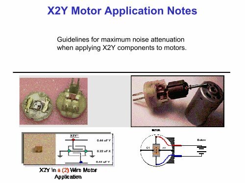
X2Y Motor Application Notes
X2Y Motor Application Notes
X2Y Motor Application Notes
- No tags were found...

Create successful ePaper yourself
Turn your PDF publications into a flip-book with our unique Google optimized e-Paper software.
<strong>X2Y</strong> <strong>Motor</strong> <strong>Application</strong> <strong>Notes</strong>GUIDELINE 1.It is important to recognize that <strong>X2Y</strong> is a bypass component. Because the chiphas side terminations, it is often confused for a feed through. <strong>X2Y</strong>’s filteringcharacteristics are maximized as a dual line bypass device.<strong>X2Y</strong>
<strong>X2Y</strong> <strong>Motor</strong> <strong>Application</strong> <strong>Notes</strong>GUIDELINE 1. (Continued)Both ground terminations of <strong>X2Y</strong>, (G1 and G2), must be attached toground for maximum noise attenuation.G1ABG2
<strong>X2Y</strong> <strong>Motor</strong> <strong>Application</strong> <strong>Notes</strong>GUIDELINE 1. (continued)These two insertion loss graphs illustrate the results of grounding <strong>X2Y</strong> properlyThis graph shows the effect of connecting justone of the ground terminations of the componentWhen two terminations are attached impedanceis lowered and the resonant frequency of thecircuit is shifted higher by 80 MHz.
<strong>X2Y</strong> <strong>Motor</strong> <strong>Application</strong> <strong>Notes</strong>GUIDELINE 2.Remove all currently used suppression.. The <strong>X2Y</strong> 0.4uF is the best value to start withfor broadband filtering.<strong>X2Y</strong> 0.4uF
<strong>X2Y</strong> <strong>Motor</strong> <strong>Application</strong> <strong>Notes</strong>GUIDELINE 3. Provide a metal or metalized motor housing. This is necessary becausewhen <strong>X2Y</strong> is attached properly to the motor housing, the housing itself is used incombination with the component as a reference to cancel the noise (antenna theory).Note: The motor itself does not need to be grounded.Plastic motor housingMetalized motor housing with plastic end capPlastic end capPlastic end capImproved
<strong>X2Y</strong> <strong>Motor</strong> <strong>Application</strong> <strong>Notes</strong>GUIDELINE 3. continuedHere is an example of a motor with a metal housing and plastic end cap.Inside the plastic end cap are metalized ground tabs that stick out andmake contact with the motor housing when the two are pushed together.The previous suppression has been removed and a single <strong>X2Y</strong> is installedbetween the power leads, then both ground terminations of the componentare soldered to the ground connections of the plastic end cap.Metal contactsMetal contactsMetal contacts
<strong>X2Y</strong> <strong>Motor</strong> <strong>Application</strong> <strong>Notes</strong>GUIDELINE 5.If possible, provide a metal or metalized end cap. This will help with containment offields that can radiate around the plastic end cap and couple back onto the lines.Note: The motor itself does not need to be grounded.Noise can couple outside the motor casewhen using a plastic end cap.A metal end cap works as a shield to contain thenoise within the motor case.Improved
<strong>X2Y</strong> <strong>Motor</strong> <strong>Application</strong> <strong>Notes</strong>GUIDELINE 5. continuedNote the improved suppression results after applying a metalized end cap.<strong>X2Y</strong> 1410 0.44uF
<strong>X2Y</strong> <strong>Motor</strong> <strong>Application</strong> <strong>Notes</strong>GUIDELINE 6.For best attachment of the <strong>X2Y</strong> component, power leads shouldexit the motor housing in close proximity to each other.ORPoor DesignImprovedImproved
<strong>X2Y</strong> <strong>Motor</strong> <strong>Application</strong> <strong>Notes</strong>GUIDELINE 7.The <strong>X2Y</strong> device is most effective when placed at the inside or outside of themetalized housing where the wires exit the motor. The <strong>X2Y</strong> componentis the last device the noise should pass through when leaving the motor.<strong>X2Y</strong><strong>X2Y</strong>Or
<strong>X2Y</strong> <strong>Motor</strong> <strong>Application</strong> <strong>Notes</strong>GUIDELINE 7. (continued)Here are the test results when guideline 7 is applied. In this example the <strong>X2Y</strong>component is placed inside of the housing and between the leads as the leadsexit the housing. Not that noise cancellation is near total as the <strong>X2Y</strong> resultsfollow the ambient in this emission test.ConductedEmissions<strong>X2Y</strong> 1410 0.44uF
<strong>X2Y</strong> <strong>Motor</strong> <strong>Application</strong> <strong>Notes</strong>GUIDELINE 8.There should be a low inductive (at high frequency) attachment of the leads tothe component terminals. Note that the traces to the component are wide (lowinductance) and then narrow down when attached to the ground terminations.Solder Braid<strong>Motor</strong> housing(-) LeadAG1B(+) LeadG2Trace is connected tomotor housing
<strong>X2Y</strong> <strong>Motor</strong> <strong>Application</strong> <strong>Notes</strong>GUIDELINE 8. (continued)“G1 & G2” on the <strong>X2Y</strong> device must be connected to the same low impedance trace.A continuous trace between the “G1 & G2” terminations of the component reducesattachment inductance. When the trace is continuous, it is in parallel to the internalground electrodes of the component and impedance to ground (or the motor case)is lowered.G1<strong>Motor</strong> housingAB(+)Lead(-)LeadG2Continuous trace for G1 & G2connection and grounding tomotor case.
<strong>X2Y</strong> <strong>Motor</strong> <strong>Application</strong> <strong>Notes</strong>GUIDLINE 8. (continued)When there are long thin leads to the G1 and G2 terminations of the <strong>X2Y</strong>component, noise is prevented from canceling on the motor case because theinductance associated with the leads is high impedance to ground (or motorcase). A general rule of thumb is to keep lead length less than ¼” long.Noise is prevented from getting toThe motor case for cancellation= NoiseAB<strong>Motor</strong> Case
<strong>X2Y</strong> <strong>Motor</strong> <strong>Application</strong> <strong>Notes</strong>GUIDLINE 8. (continued)Conversely, if the traces to the A & B terminations of the component are too longor thin, the inductance associated with the leads is a high impedance to the <strong>X2Y</strong>component. This prevents noise from getting to the component so that it can becancelled to ground or the motor case. A general rule of thumb is to keep leadlength less than ¼” long.Noise is blocked from getting to thecomponent for cancellation= NoiseG1B<strong>Motor</strong> CaseContinuous low impedance trace
<strong>X2Y</strong> <strong>Motor</strong> <strong>Application</strong> <strong>Notes</strong>GUIDLINE 9.When filter application is difficult because of lead locations or attachmentconstraints, brush card holders can offer a quick and universal solution forApplying the <strong>X2Y</strong> components.3 Brush <strong>Motor</strong> Filter, Insulated Metal ...Bottom SurfaceVIARotorTop SurfaceViaA<strong>X2Y</strong>ConnectorABBVia's<strong>X2Y</strong> FilterConnectorMountingHolesSolderVia'sConnectorInsulation<strong>X2Y</strong>Section AAVia'sViaSection BBSolder Metal SolderConductorSection AA<strong>X2Y</strong> Attenuators,LLC. 3 Brush Solid Core Carrier October 30, 2000 Issue 2 Drawing # 2131
<strong>X2Y</strong> <strong>Motor</strong> <strong>Application</strong> <strong>Notes</strong>GUIDLINE 9. (continued)Brush Card DesignTwo Speed <strong>Motor</strong> Attachment for <strong>X2Y</strong>Low SpeedGroundG1 & G2 eachConnected to Ground TraceBrush CardInsulationConductor / Trace<strong>X2Y</strong>High SpeedJumper Wire forBrush Connection.Riveted to Case GroundRiveted to Case GroundGround Trace / AreaScrew to Case Ground<strong>Motor</strong> CaseNote: (1) The "White" conductor / trace on brush card could be changed to jumper wire and then adding additionalground area as indicated above with the dashed line.2331, 2 Speed <strong>Motor</strong> with <strong>X2Y</strong> Circuit, Issue 1, 10-30-2000
<strong>X2Y</strong> <strong>Motor</strong> <strong>Application</strong> <strong>Notes</strong>GUIDLINE 9. (continued)Brush Card Design<strong>Motor</strong> Connections<strong>X2Y</strong><strong>X2Y</strong><strong>X2Y</strong>Perimeter GroundRotorBrush Cardwith Rotor PenetrationConductive MaterialBrush Cardwithout Rotor Penetration<strong>Notes</strong>:(1) Can use 1 or 2 <strong>X2Y</strong> devices as required to meet specific filtering needs.(2) Material recomendations are:A) Plated or metalized PlasticB) Insulated Metal(3) Symmetry and Balance are very important.<strong>X2Y</strong> RPatent Pending<strong>X2Y</strong> Attenuators, LLC.Drawing # 2393Brush Card IdeasIssue 0, 10-22-2000
<strong>X2Y</strong> <strong>Motor</strong> <strong>Application</strong> <strong>Notes</strong>GUIDLINE 9. (continued)Brush Card DesignHigh FrequencyFilterVIAVia's Plated Thru HolesA5000pfConnectorAA0.47ufConnectorARotorTop SurfaceInsulatorMountingHolesConductiveSurfaceBottom SurfaceLow FrequencyFilterVia'sHigh FrequencyFilter<strong>X2Y</strong>Section AAConnectorSolder or WeldBrushSection AA<strong>X2Y</strong>Low FrequencyFilter<strong>X2Y</strong> Attenuators, LLCThree Brush <strong>Motor</strong> FilterScale: NTS Drawing #2126Date:10-30-2000 Drawn by: KWMIssue: 5
<strong>X2Y</strong> <strong>Motor</strong> <strong>Application</strong> <strong>Notes</strong>GUIDLINE 9. (continued)Brush Card DesignBottom ViewProprietary <strong>X2Y</strong> DrawingInternal LayerMountingHoleVia'sConductiveTraceConductorTop ViewVia'sConductiveTraceconnectorA A A AconnectorAconnectorAMountingHoleInsulatorVia's<strong>X2Y</strong> FilterPerimeterGroundConductiveTrace<strong>X2Y</strong> FilterSide ViewNote: Preferred Connector MaterialConductive MetalCross SectionView AA<strong>X2Y</strong> Attenuators,LLC.Connector Face3 Brush Filter Carrier, multi-level PCBIssue 1October 30, 2000Drawing # 2132
<strong>X2Y</strong> <strong>Motor</strong> <strong>Application</strong> <strong>Notes</strong>Other Considerations:A 1410 0.4 u F <strong>X2Y</strong> in X7R can handle approx. 1 ½ to 2A (depending onfrequency) of RF energy before breakdown. Higher levels of RF energymay need a larger <strong>X2Y</strong> device or the RF may have to be clamped to alower level with a diode or Zener diode.<strong>X2Y</strong>
<strong>X2Y</strong> <strong>Motor</strong> <strong>Application</strong> <strong>Notes</strong>Other Considerations:It is important that there is no paint or oil when you make groundconnection to the motor case, this will produce a poor groundat high frequencies.There should be a goodclean contact for a lowimpedance high frequencyground connection
<strong>X2Y</strong> <strong>Motor</strong> <strong>Application</strong> <strong>Notes</strong>Other Considerations: Holes or slots in the motor case can radiateenergy leading to component ineffectiveness. Keep the vent holesaway from the brushes (noise source).