04. 01 Directory chapter 04 Connectors with press-in termination
04. 01 Directory chapter 04 Connectors with press-in termination
04. 01 Directory chapter 04 Connectors with press-in termination

Create successful ePaper yourself
Turn your PDF publications into a flip-book with our unique Google optimized e-Paper software.
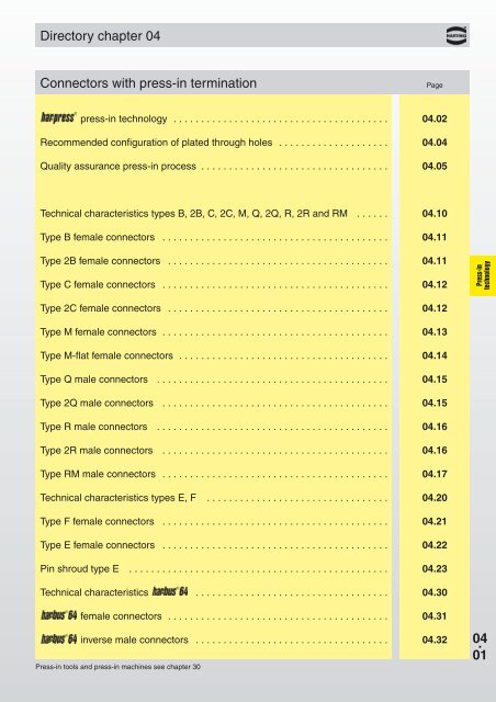
<strong>Directory</strong> <strong>chapter</strong> <strong>04</strong><br />
<strong>Connectors</strong> <strong>with</strong> <strong>press</strong>-<strong>in</strong> term<strong>in</strong>ation<br />
Page<br />
<strong>press</strong>-<strong>in</strong> technology . . . . . . . . . . . . . . . . . . . . . . . . . . . . . . . . . . . . . . . <strong><strong>04</strong>.</strong>02<br />
Recommended configuration of plated through holes . . . . . . . . . . . . . . . . . . . . <strong><strong>04</strong>.</strong><strong>04</strong><br />
Quality assurance <strong>press</strong>-<strong>in</strong> process . . . . . . . . . . . . . . . . . . . . . . . . . . . . . . . . . . <strong><strong>04</strong>.</strong>05<br />
Technical characteristics types B, 2B, C, 2C, M, Q, 2Q, R, 2R and RM . . . . . . <strong><strong>04</strong>.</strong>10<br />
Type B female connectors . . . . . . . . . . . . . . . . . . . . . . . . . . . . . . . . . . . . . . . . . <strong><strong>04</strong>.</strong>11<br />
Type 2B female connectors . . . . . . . . . . . . . . . . . . . . . . . . . . . . . . . . . . . . . . . . <strong><strong>04</strong>.</strong>11<br />
Type C female connectors . . . . . . . . . . . . . . . . . . . . . . . . . . . . . . . . . . . . . . . . . <strong><strong>04</strong>.</strong>12<br />
Press-<strong>in</strong><br />
technology<br />
Type 2C female connectors . . . . . . . . . . . . . . . . . . . . . . . . . . . . . . . . . . . . . . . . <strong><strong>04</strong>.</strong>12<br />
Type M female connectors . . . . . . . . . . . . . . . . . . . . . . . . . . . . . . . . . . . . . . . . . <strong><strong>04</strong>.</strong>13<br />
Type M-flat female connectors . . . . . . . . . . . . . . . . . . . . . . . . . . . . . . . . . . . . . . <strong><strong>04</strong>.</strong>14<br />
Type Q male connectors . . . . . . . . . . . . . . . . . . . . . . . . . . . . . . . . . . . . . . . . . . <strong><strong>04</strong>.</strong>15<br />
Type 2Q male connectors . . . . . . . . . . . . . . . . . . . . . . . . . . . . . . . . . . . . . . . . . <strong><strong>04</strong>.</strong>15<br />
Type R male connectors . . . . . . . . . . . . . . . . . . . . . . . . . . . . . . . . . . . . . . . . . . <strong><strong>04</strong>.</strong>16<br />
Type 2R male connectors . . . . . . . . . . . . . . . . . . . . . . . . . . . . . . . . . . . . . . . . . <strong><strong>04</strong>.</strong>16<br />
Type RM male connectors . . . . . . . . . . . . . . . . . . . . . . . . . . . . . . . . . . . . . . . . . <strong><strong>04</strong>.</strong>17<br />
Technical characteristics types E, F . . . . . . . . . . . . . . . . . . . . . . . . . . . . . . . . . <strong><strong>04</strong>.</strong>20<br />
Type F female connectors . . . . . . . . . . . . . . . . . . . . . . . . . . . . . . . . . . . . . . . . . <strong><strong>04</strong>.</strong>21<br />
Type E female connectors . . . . . . . . . . . . . . . . . . . . . . . . . . . . . . . . . . . . . . . . . <strong><strong>04</strong>.</strong>22<br />
P<strong>in</strong> shroud type E . . . . . . . . . . . . . . . . . . . . . . . . . . . . . . . . . . . . . . . . . . . . . . . <strong><strong>04</strong>.</strong>23<br />
Technical characteristics . . . . . . . . . . . . . . . . . . . . . . . . . . . . . . . . . . . <strong><strong>04</strong>.</strong>30<br />
female connectors . . . . . . . . . . . . . . . . . . . . . . . . . . . . . . . . . . . . . . . . <strong><strong>04</strong>.</strong>31<br />
<strong>in</strong>verse male connectors . . . . . . . . . . . . . . . . . . . . . . . . . . . . . . . . . . . <strong><strong>04</strong>.</strong>32<br />
Press-<strong>in</strong> tools and <strong>press</strong>-<strong>in</strong> mach<strong>in</strong>es see <strong>chapter</strong> 30<br />
<strong>04</strong> .<br />
<strong>01</strong>
Press-<strong>in</strong> technology<br />
Solderless term<strong>in</strong>ation for connectors has proven to<br />
be reliable for decades. Today the use of <strong>press</strong>-<strong>in</strong><br />
connectors encompasses all fields of electrical and<br />
electronical applications.<br />
Press<strong>in</strong>g of electrical components, ma<strong>in</strong>ly connectors,<br />
is characterised through the match<strong>in</strong>g of the connector<br />
p<strong>in</strong> and the plated through hole of the pcb. Whereas<br />
the desired electrical characteristics can be atta<strong>in</strong>ed<br />
relatively <strong>in</strong>dependant from the design of the <strong>press</strong>-<strong>in</strong><br />
zone, the mechanical characteristics of the <strong>press</strong>-<strong>in</strong><br />
zone are crucial for the reliable assembly of connectors<br />
where pcb's have different surfaces.<br />
bus board <strong>with</strong><br />
<strong>press</strong>-<strong>in</strong> connectors<br />
Press-<strong>in</strong><br />
technology<br />
Although the scope of requirements at the <strong>press</strong>-<strong>in</strong><br />
process is generally def<strong>in</strong>ed <strong>in</strong> time-tested specifications,<br />
the novel <strong>press</strong>-<strong>in</strong> zones should offer an optimal handl<strong>in</strong>g<br />
and a reliable term<strong>in</strong>ation. Essentially, this is guaranteed<br />
through the design of the <strong>press</strong>-<strong>in</strong> zone and the<br />
meticulous observance of tolerances. HARTING has<br />
been us<strong>in</strong>g FEM simulations for the calculation and<br />
optimisation of <strong>press</strong>-<strong>in</strong> zones for a long period of time.<br />
This expertise allows us to simulate various pcb<br />
configurations very accurate.<br />
FEM simulation<br />
of the needle eye<br />
<strong>press</strong>-<strong>in</strong> zone<br />
Phase 1<br />
The process<strong>in</strong>g of <strong>press</strong>-<strong>in</strong> connectors can be divided<br />
<strong>in</strong>to 3 phases, conta<strong>in</strong><strong>in</strong>g both mechanical and<br />
metallurgical operations:<br />
Press die<br />
(Flat rock)<br />
1. Center<strong>in</strong>g and plac<strong>in</strong>g of the term<strong>in</strong>ation p<strong>in</strong>s<br />
Insert block<br />
<strong>04</strong> .<br />
02<br />
The center<strong>in</strong>g of connectors before <strong>press</strong><strong>in</strong>g is<br />
important <strong>in</strong> order to prevent damage to the pcb<br />
and the term<strong>in</strong>ation p<strong>in</strong>s. Center<strong>in</strong>g can be<br />
omitted when connectors are <strong>press</strong>ed us<strong>in</strong>g a flat<br />
rock die.<br />
HARTING offers <strong>in</strong>sert blocks for male connectors<br />
to make the center<strong>in</strong>g of connectors unnecessary.<br />
Connector<br />
Multilayer<br />
pcb
Press-<strong>in</strong> technology<br />
2. Press<strong>in</strong>g <strong>in</strong> the p<strong>in</strong>s<br />
Phase 2<br />
In the <strong>press</strong>-<strong>in</strong> process the <strong>in</strong>sertion force is<br />
cont<strong>in</strong>uously transformed <strong>in</strong>to com<strong>press</strong>ion force.<br />
The result<strong>in</strong>g friction frees the contact<strong>in</strong>g bars of<br />
<strong>in</strong>sulat<strong>in</strong>g films. Superfluous plat<strong>in</strong>g (t<strong>in</strong>) is<br />
transferred <strong>with</strong><strong>in</strong> the plated through hole. A gastight<br />
connection of fresh non-oxidised metal<br />
surfaces is obta<strong>in</strong>ed.<br />
3. Obta<strong>in</strong><strong>in</strong>g the f<strong>in</strong>al position<br />
The <strong>press</strong>-<strong>in</strong> operation should be term<strong>in</strong>ated as<br />
soon as the connector obta<strong>in</strong>s its f<strong>in</strong>al position on<br />
the pcb to avoid unnecessary com<strong>press</strong>ive stress.<br />
The <strong>press</strong>-<strong>in</strong> mach<strong>in</strong>es of HARTING feature<br />
automatic term<strong>in</strong>ation of the <strong>press</strong>-<strong>in</strong> operation<br />
<strong>in</strong>dependant of pcb thickness and surface<br />
properties.<br />
Phase 3<br />
Press-<strong>in</strong><br />
technology<br />
The entire dynamic <strong>press</strong>-<strong>in</strong> process is characterised<br />
through changes of the <strong>press</strong>-<strong>in</strong> force that can be<br />
statistically evaluated. HARTING records the changes<br />
of force <strong>with</strong> the help of special software. This is an<br />
important step towards permanent process control and<br />
documented manufactur<strong>in</strong>g data.<br />
The -zone is based on the <strong>in</strong>dustry renowned<br />
needle eye technology. Its special design allows for<br />
compensation of tolerances of pcb surface properties<br />
(eg. superfluous t<strong>in</strong> plat<strong>in</strong>g). The excessive material is<br />
displaced <strong>with</strong><strong>in</strong> the plated through hole, whereby a<br />
gas-tight and corrosion resistant electrical connection<br />
is assured.<br />
Diameter<br />
plated through hole<br />
1.09 mm<br />
(max.)<br />
M 29:1<br />
II<br />
I<br />
M 58:1<br />
Diameter<br />
plated through hole<br />
0.99-1.00 mm<br />
(nom<strong>in</strong>al)<br />
M 29:1<br />
II<br />
I<br />
M 58:1<br />
Diameter<br />
plated through hole<br />
0.92-0.94 mm<br />
(m<strong>in</strong>.)<br />
M 29:1<br />
II<br />
I<br />
M 58:1<br />
II<br />
II<br />
II<br />
M 58:1<br />
M 58:1<br />
M 58:1<br />
I<br />
I<br />
I<br />
Cross section of a pcb 2.4 mm thick <strong>with</strong> various hole diameters<br />
<strong>04</strong> .<br />
03
Recommended configuration of plated through holes<br />
Due to the high deformation resistance and resilience of<br />
contacts, they can be easily and repeatedly<br />
removed <strong>in</strong> case of repairs <strong>with</strong>out impairment to their<br />
function<strong>in</strong>g.<br />
is extremely versatile and offers a reliable<br />
electrical contact, therefore it is especially well suited<br />
for applications <strong>with</strong> these surfaces.<br />
Please contact us for detailed test reports.<br />
chem. Sn<br />
Benefits of the <strong>press</strong>-<strong>in</strong> technology<br />
l Thermal shocks associated <strong>with</strong> the solder<strong>in</strong>g<br />
process and the risk of the board malfunction are<br />
avoided.<br />
pure Cu<br />
Pd<br />
Au<br />
Ag<br />
Press-<strong>in</strong><br />
technology<br />
l No need for the subsequent clean<strong>in</strong>g of the<br />
assembled pcb’s<br />
l Additional wrap connections are made possible by<br />
us<strong>in</strong>g connectors <strong>with</strong> long p<strong>in</strong>s<br />
l Unlimited and efficient process<strong>in</strong>g of partially goldplated<br />
p<strong>in</strong>s for rear I/O - manual solder<strong>in</strong>g is no<br />
longer necessary!<br />
Recommended configuration of plated through<br />
holes<br />
In addition to the hot-air-level (HAL) pcb surfaces are<br />
gett<strong>in</strong>g more important. Due to their different properties,<br />
such as mechanical strength and coefficient<br />
of friction we recommend the follow<strong>in</strong>g configuration<br />
of pcb through holes.<br />
Sketch:<br />
<strong>press</strong>-<strong>in</strong> zone<br />
<strong>in</strong> plated through hole<br />
T<strong>in</strong>-lead plated Hole 1.15 ±0.025 mm<br />
PCB Cu m<strong>in</strong>. 25 µm<br />
(HAL) Sn max. 15 µm<br />
acc. EN 60 352-5 Plated hole 0.94-1.09 mm<br />
Drilled hole<br />
Chemical Hole 1.15 ±0.025 mm<br />
t<strong>in</strong>-plated PCB Cu m<strong>in</strong>. 25 µm<br />
Sn m<strong>in</strong>. 0.8 µm<br />
Plated hole<br />
1.00-1.10 mm<br />
Au / Ni plated PCB Hole 1.15 ±0.025 mm<br />
Cu m<strong>in</strong>. 25 µm<br />
Ni 3-7 µm<br />
Au 0.05-0.12 µm<br />
Plated hole<br />
1.00-1.10 mm<br />
Silver plated PCB Hole 1.15 ±0.025 mm<br />
Cu m<strong>in</strong>. 25 µm<br />
Ag 0.1-0.3 µm<br />
Plated hole<br />
1.00-1.10 mm<br />
Cu<br />
<strong>04</strong> .<br />
<strong>04</strong><br />
OSP Hole 1.15 ±0.025 mm<br />
copper plated PCB Cu m<strong>in</strong>. 25 µm<br />
Plated hole<br />
1.00-1.10 mm<br />
PCB board thickness: ≥ 1,6 mm<br />
pcb holes<br />
for <strong>press</strong>-<strong>in</strong><br />
process <strong>in</strong> acc.<br />
to EN 60 352-5<br />
Sn<br />
Plated through hole
Quality assurance <strong>press</strong>-<strong>in</strong> process<br />
Quality control of the <strong>press</strong>-<strong>in</strong> term<strong>in</strong>ation<br />
The <strong>press</strong>-<strong>in</strong> force correlates <strong>with</strong> the diameter of the<br />
plated through hole and <strong>with</strong> the friction coefficient of<br />
the surface; therefore it can be used for a cont<strong>in</strong>uous<br />
monitor<strong>in</strong>g of the process.<br />
The retention force, as an <strong>in</strong>direct measure of the<br />
normal force, serves to qualify the process or random<br />
tests<br />
Press-<strong>in</strong> force / retemtion force per p<strong>in</strong> (<strong>in</strong> N)<br />
pcb thickness: 1.6 mm to 3.2 mm<br />
Plat<strong>in</strong>g of the <strong>press</strong>-<strong>in</strong> zone: Sn<br />
Plat<strong>in</strong>g of the hole:<br />
Sn<br />
m<strong>in</strong>./max. retention force<br />
m<strong>in</strong>./max. <strong>press</strong>-<strong>in</strong> force<br />
Press-<strong>in</strong><br />
technology<br />
Hole diameter (mm)<br />
Typical <strong>press</strong>-<strong>in</strong> and retention forces for the har·<strong>press</strong><br />
The automatic <strong>press</strong>-<strong>in</strong> mach<strong>in</strong>es of HARTING feature<br />
a graphical user <strong>in</strong>terface for monitor<strong>in</strong>g the process<br />
and the quality of the <strong>press</strong>-<strong>in</strong> term<strong>in</strong>ation (see <strong>chapter</strong><br />
30).<br />
HARTING assists you <strong>with</strong> the most advanced quality<br />
assurance methods beyond the usual scope.<br />
X-ray photo of a <strong>press</strong>ed-<strong>in</strong> connector<br />
<strong>04</strong> .<br />
05
Technical characteristics<br />
Types<br />
B, 2B, C, 2C, M, Q, 2Q, R, 2R and RM<br />
Press-<strong>in</strong><br />
technology<br />
Number of contacts 32-96<br />
Contact spac<strong>in</strong>g (mm) 2.54<br />
Work<strong>in</strong>g current<br />
2 A max.<br />
see current carry<strong>in</strong>g capacity chart<br />
Clearance<br />
≥ 1.2 mm<br />
Creepage<br />
≥ 1.2 mm<br />
Work<strong>in</strong>g voltage<br />
The work<strong>in</strong>g voltage also depends accord<strong>in</strong>g to the safety<br />
on the clearance and creepage regulations of the equipment<br />
dimensions of the pcb itself and Explanations see <strong>chapter</strong> 00<br />
the associated wir<strong>in</strong>g<br />
Test voltage U r.m.s.<br />
1 kV<br />
Contact resistance<br />
≤ 15 mΩ<br />
Insulation resistance<br />
≥ 10 12 Ω<br />
Temperature range – 40 °C … + 105 °C<br />
The upper temperature is<br />
limited by the property of the<br />
pcb material<br />
Current carry<strong>in</strong>g capacity<br />
The current carry<strong>in</strong>g capacity is limited by maximum temperature of<br />
materials for <strong>in</strong>serts and contacts <strong>in</strong>clud<strong>in</strong>g term<strong>in</strong>als. The current<br />
capacity curve is valid for cont<strong>in</strong>uous, non <strong>in</strong>terrupted current loaded<br />
contacts of connectors when simultaneous power on all contacts is<br />
given, <strong>with</strong>out exceed<strong>in</strong>g the maximum temperature.<br />
Control and test procedures accord<strong>in</strong>g to DIN IEC 60 512<br />
Work<strong>in</strong>g current<br />
Ambient temperature<br />
Electrical term<strong>in</strong>ation<br />
Male and female connectors<br />
Diameter of pcb plated through holes<br />
pcb thickness<br />
Recommended pcb holes for<br />
<strong>press</strong>-<strong>in</strong> process <strong>in</strong> acc. to EN 60 352-5 2)<br />
Compliant <strong>press</strong>-<strong>in</strong><br />
term<strong>in</strong>ations<br />
0.94-1.09 mm<br />
≥ 1.6 mm<br />
Insertion and <strong>with</strong>drawal force<br />
32pol. ≤ 30 N<br />
48pol. ≤ 45 N<br />
64pol. ≤ 60 N<br />
96pol. ≤ 90 N<br />
Materials<br />
Mould<strong>in</strong>gs<br />
Contacts<br />
Contact surface<br />
Contact zone<br />
Press-<strong>in</strong> zone<br />
Wrap zone<br />
<strong>with</strong> selectively gold plated<br />
wrap posts<br />
Thermoplastic res<strong>in</strong>,<br />
glass-fibre filled, UL 94-V0<br />
Copper alloy<br />
plated accord<strong>in</strong>g to<br />
performance level 1)<br />
t<strong>in</strong>ned<br />
t<strong>in</strong>ned<br />
wrap zone: t<strong>in</strong>ned<br />
<strong>in</strong>terface zone: gold plated<br />
accord<strong>in</strong>g to<br />
performance level 3<br />
<strong>04</strong> .<br />
10<br />
1)<br />
Explanation of performance levels see <strong>chapter</strong> 00<br />
2)<br />
for details see page <strong><strong>04</strong>.</strong><strong>04</strong><br />
Mat<strong>in</strong>g conditions see <strong>chapter</strong> 00<br />
Tool<strong>in</strong>g see <strong>chapter</strong> 30
DIN 41 612 · Types B and 2B<br />
Number of contacts<br />
64, 32<br />
Female connectors<br />
Number Contact<br />
Identification of contacts arrangement<br />
Female connector<br />
<strong>with</strong> <strong>press</strong>-<strong>in</strong> term<strong>in</strong>ations<br />
Part No. Performance levels accord<strong>in</strong>g to DIN 41 612. Explanation <strong>chapter</strong> 00<br />
3 2 1<br />
5.3 mm<br />
Type B<br />
64 Performance level 3 09 02 264 6850<br />
on request<br />
Performance level 1<br />
on request<br />
Type 2B<br />
32 09 22 232 6850<br />
Press-<strong>in</strong><br />
technology<br />
Dimensions<br />
row<br />
position<br />
b c d e<br />
Type B 31 x 2.54 (= 78.74) 90 ± 0.1 85.0 – 0.2 94.9 ± 0.1<br />
Type 2B 15 x 2.54 (= 38.1 ) 50 ± 0.1 44.4 – 0.2 54.9 ± 0.1<br />
Board drill<strong>in</strong>gs<br />
Mount<strong>in</strong>g side<br />
all holes<br />
X<br />
position<br />
row<br />
Other contact arrangements on request<br />
1)<br />
refer to recommended configuration of pcb holes, see page <strong><strong>04</strong>.</strong><strong>04</strong><br />
Dimensions <strong>in</strong> mm<br />
<strong>04</strong> .<br />
11
DIN 41 612 · Types C and 2C<br />
Number of contacts<br />
96, 64,<br />
48, 32<br />
Female connectors<br />
Identification<br />
Female connector<br />
Type C<br />
<strong>with</strong> <strong>press</strong>-<strong>in</strong> term<strong>in</strong>ations<br />
4.5 mm<br />
Number Contact<br />
of contacts arrangement<br />
Part No. Performance levels accord<strong>in</strong>g to DIN 41 612. Explanation <strong>chapter</strong> 00<br />
3 2 1<br />
96 09 03 296 7850 09 03 296 6850 09 03 296 2850<br />
64 09 03 264 7850 09 03 264 6850 09 03 264 2850<br />
32 09 03 232 7850 09 03 232 6850 09 03 232 2850<br />
Press-<strong>in</strong><br />
technology<br />
13.2 mm<br />
96<br />
64<br />
09 03 296 6851<br />
l09 03 296 6861 l<br />
09 03 264 6851<br />
l09 03 264 6861 l<br />
17 mm<br />
96<br />
09 03 296 6852<br />
l09 03 296 6862 l<br />
Female connector<br />
Type 2C<br />
<strong>with</strong> <strong>press</strong>-<strong>in</strong> term<strong>in</strong>ations<br />
4.5 mm<br />
48 09 23 248 6850<br />
Dimensions<br />
row<br />
position<br />
a b c d e f g<br />
Type C 4.5 31 90 85.0 94.9 0.3 0.75<br />
Type C 13.2 31 90 85.0 94.9 0.6 0.60<br />
Type C 17.0 31 90 85.0 94.9 0.6 0.60<br />
Type 2C 4.5 15 50 44.4 54.9 0.3 0.75<br />
Board drill<strong>in</strong>gs<br />
Mount<strong>in</strong>g side<br />
all holes<br />
row<br />
<strong>04</strong> .<br />
12<br />
l<br />
Wrap posts for <strong>in</strong>terfac<strong>in</strong>g selectively gold plated (performance level 3)<br />
Other contact arrangements on request<br />
1)<br />
refer to recommended configuration of pcb holes, see page <strong><strong>04</strong>.</strong><strong>04</strong><br />
position<br />
Dimensions <strong>in</strong> mm
DIN 41 612 · Type M<br />
Number of contacts<br />
78+2, 60+4<br />
42+6, 24+8<br />
Female connectors<br />
Number Contact<br />
Identification of contacts arrangement<br />
Female connector<br />
<strong>with</strong> <strong>press</strong>-<strong>in</strong> term<strong>in</strong>ations<br />
Part No. Performance levels accord<strong>in</strong>g to DIN 41 612. Explanation <strong>chapter</strong> 00<br />
3 2 1<br />
78 + 2 09 03 278 6850<br />
4.5 mm<br />
60 + 4 09 03 260 6850<br />
Performance level 3<br />
on request<br />
42 + 6 09 03 242 6850<br />
Performance level 1<br />
on request<br />
Dimensions<br />
24 + 8 09 03 224 6850<br />
Press-<strong>in</strong><br />
technology<br />
row<br />
position<br />
Panel cut out<br />
Order high current, high voltage, coaxial and<br />
fibre optic contacts separately, see <strong>chapter</strong> <strong>01</strong><br />
Contact arrangement<br />
view from term<strong>in</strong>ation side<br />
Board drill<strong>in</strong>gs<br />
Mount<strong>in</strong>g side<br />
all holes<br />
position<br />
row<br />
Other contact arrangements on request<br />
1)<br />
refer to recommended configuration of pcb holes, see page <strong><strong>04</strong>.</strong><strong>04</strong><br />
Type<br />
c<br />
78 + 2 25 x 2.54 = 63.50<br />
60 + 4 19 x 2.54 = 48.26<br />
42 + 6 13 x 2.54 = 33.02<br />
24 + 8 7 x 2.54 = 17.78<br />
Dimensions<br />
<strong>in</strong> mm<br />
<strong>04</strong> .<br />
13
DIN 41 612 · complementary type M-flat<br />
Number of contacts<br />
78+2, 60+4<br />
42+6, 24+8<br />
Female connectors<br />
Number Contact<br />
Identification of contacts arrangement<br />
Female connector<br />
<strong>with</strong> <strong>press</strong>-<strong>in</strong> term<strong>in</strong>ations<br />
Part No. Performance levels accord<strong>in</strong>g to DIN 41 612. Explanation <strong>chapter</strong> 00<br />
3 2 1<br />
78 + 2 09 03 278 6830<br />
4.5 mm<br />
60 + 4<br />
Performance level 3<br />
09 03 260 6830<br />
on request<br />
42 + 6 09 03 242 6830<br />
Performance level 1<br />
on request<br />
Press-<strong>in</strong><br />
technology<br />
High current female contact<br />
<strong>with</strong> <strong>press</strong>-<strong>in</strong> term<strong>in</strong>ation<br />
24 + 8 09 03 224 6830<br />
40 A<br />
09 03 000 6250<br />
Dimensions<br />
row<br />
position<br />
Order high current, high voltage, coaxial and<br />
fibre optic contacts separately, see <strong>chapter</strong> <strong>01</strong><br />
Panel cut out<br />
Contact arrangement<br />
view from term<strong>in</strong>ation side<br />
all holes<br />
Board drill<strong>in</strong>gs<br />
Mount<strong>in</strong>g side<br />
position<br />
<strong>04</strong> .<br />
14<br />
Other contact arrangements on request<br />
1)<br />
refer to recommended configuration of pcb holes, see page <strong><strong>04</strong>.</strong><strong>04</strong><br />
row<br />
Type<br />
c<br />
78 + 2 25 x 2.54 = 63.50<br />
60 + 4 19 x 2.54 = 48.26<br />
42 + 6 13 x 2.54 = 33.02<br />
24 + 8 7 x 2.54 = 17.78<br />
Dimensions<br />
<strong>in</strong> mm
DIN 41 612 · Type Q<br />
DIN 41 612 · complementary type 2Q<br />
Number of contacts<br />
64, 32<br />
Male connectors<br />
Identification<br />
Male connector<br />
Type Q<br />
<strong>with</strong> <strong>press</strong>-<strong>in</strong> term<strong>in</strong>ations<br />
Number Contact<br />
of contacts arrangement<br />
Part No. Performance levels accord<strong>in</strong>g to DIN 41 612. Explanation <strong>chapter</strong> 00<br />
3 2 1<br />
5.0 mm<br />
64 09 72 164 79<strong>04</strong> 09 72 164 69<strong>04</strong><br />
62 + 2 s 09 72 164 7954 09 72 164 6954<br />
13 mm<br />
Male connector<br />
Type 2Q<br />
<strong>with</strong> <strong>press</strong>-<strong>in</strong> term<strong>in</strong>ations<br />
64<br />
09 72 164 7985 09 72 164 6985<br />
l09 72 164 7974 l l 09 72 164 6974 l<br />
62 + 2 s 09 72 164 7995 09 72 164 6995<br />
performance level 1<br />
or special<br />
gold plat<strong>in</strong>g<br />
on request<br />
Press-<strong>in</strong><br />
technology<br />
5.0 mm<br />
32 09 27 132 79<strong>04</strong> 09 27 132 69<strong>04</strong><br />
30 + 2 s 09 27 132 7954 09 27 132 6954<br />
13 mm<br />
32 09 27 132 7985 09 27 132 6985<br />
30 + 2 s 09 27 132 7995 09 27 132 6995<br />
Dimensions<br />
Type Q<br />
Type 2Q<br />
row<br />
a<br />
5<br />
13<br />
row<br />
a<br />
5<br />
13<br />
position<br />
position<br />
Board drill<strong>in</strong>gs<br />
Mount<strong>in</strong>g side<br />
all holes<br />
position<br />
all holes<br />
position<br />
row<br />
row<br />
s<br />
Male connectors <strong>with</strong> 2 lead<strong>in</strong>g contacts (0.8 mm) pos. a1 and a32/a16<br />
l<br />
Wrap posts for <strong>in</strong>terfac<strong>in</strong>g selectively gold plated (performance level 3)<br />
1)<br />
refer to recommended configuration of pcb holes, see page <strong><strong>04</strong>.</strong><strong>04</strong><br />
Dimensions<br />
<strong>in</strong> mm<br />
Other contact arrangements as<br />
well <strong>with</strong> lagg<strong>in</strong>g p<strong>in</strong>s on request<br />
<strong>04</strong> .<br />
15
DIN 41 612 · Type R<br />
DIN 41 612 · complementary type 2R<br />
Number of contacts<br />
96, 64,<br />
48, 32<br />
Male connectors<br />
Identification<br />
Male connector<br />
Type R<br />
<strong>with</strong> <strong>press</strong>-<strong>in</strong> term<strong>in</strong>ations<br />
Number Contact<br />
of contacts arrangement<br />
Part No. Performance levels accord<strong>in</strong>g to DIN 41 612. Explanation <strong>chapter</strong> 00<br />
3 2 1<br />
5.0 mm<br />
96 09 73 196 79<strong>04</strong> 09 73 196 69<strong>04</strong><br />
94 + 2 s 09 73 196 7954 09 73 196 6954<br />
64 09 73 164 79<strong>04</strong> 09 73 164 69<strong>04</strong><br />
Press-<strong>in</strong><br />
technology<br />
13 mm<br />
96<br />
09 73 196 7985 09 73 196 6985<br />
l09 73 196 7974 l l 09 73 196 6974 l<br />
94 + 2 s 09 73 196 7995 09 73 196 6995<br />
performance level 1<br />
Male connector<br />
Type 2R<br />
<strong>with</strong> <strong>press</strong>-<strong>in</strong> term<strong>in</strong>ations<br />
64<br />
09 73 164 7985 09 73 164 6985<br />
l09 73 164 7974 l l 09 73 164 6974 l<br />
or special<br />
gold plat<strong>in</strong>g<br />
on request<br />
5.0 mm<br />
48 09 28 148 79<strong>04</strong> 09 28 148 69<strong>04</strong><br />
46 + 2 s 09 28 148 7954 09 28 148 6954<br />
32 09 28 132 79<strong>04</strong> 09 28 132 69<strong>04</strong><br />
13 mm<br />
48 09 28 148 7985 09 28 148 6985<br />
46 + 2 s 09 28 148 7995 09 28 148 6995<br />
Dimensions<br />
32 09 28 132 7985 09 28 132 6985<br />
Type R A-B<br />
Type 2R<br />
A-B<br />
row a<br />
5<br />
13<br />
position<br />
row<br />
position<br />
a<br />
5<br />
13<br />
Board drill<strong>in</strong>gs<br />
Mount<strong>in</strong>g side<br />
position<br />
all holes<br />
position<br />
all holes<br />
<strong>04</strong> .<br />
16<br />
row<br />
s<br />
Male connectors <strong>with</strong> 2 lead<strong>in</strong>g contacts (0.8 mm) pos. a1 and a32/a16<br />
l<br />
Wrap posts for <strong>in</strong>terfac<strong>in</strong>g selectively gold plated (performance level 3)<br />
1)<br />
refer to recommended configuration of pcb holes, see page <strong><strong>04</strong>.</strong><strong>04</strong><br />
row<br />
Dimensions <strong>in</strong> mm<br />
Other contact arrangements also<br />
<strong>with</strong> lagg<strong>in</strong>g p<strong>in</strong>s on request
DIN 41 612 · complementary type RM<br />
Number of contacts<br />
96, 64<br />
Male connectors<br />
Identification<br />
Male connector<br />
<strong>with</strong> <strong>press</strong>-<strong>in</strong> term<strong>in</strong>ations<br />
Number Contact<br />
of contacts arrangement<br />
Part No. Performance levels accord<strong>in</strong>g to DIN 41 612. Explanation <strong>chapter</strong> 00<br />
3 2 1<br />
5.0 mm<br />
13 mm<br />
96 performance level 3 performance level 2 09 79 196 2950<br />
or special<br />
or special<br />
64<br />
gold plat<strong>in</strong>g<br />
gold plat<strong>in</strong>g<br />
09 79 164 2950<br />
on request<br />
on request<br />
96 * 09 79 196 2961*<br />
Press-<strong>in</strong><br />
technology<br />
Dimensions<br />
A-B<br />
a<br />
5<br />
13<br />
row<br />
position<br />
Board drill<strong>in</strong>gs<br />
Mount<strong>in</strong>g side<br />
position<br />
all holes<br />
row<br />
* Wrap posts for <strong>in</strong>terfac<strong>in</strong>g selectively gold plated (performance level 2)<br />
1)<br />
refer to recommended configuration of pcb holes, see page <strong><strong>04</strong>.</strong><strong>04</strong><br />
Dimensions <strong>in</strong> mm<br />
Other contact arrangements on request<br />
<strong>04</strong> .<br />
17
Technical characteristics<br />
Types E and F<br />
Press-<strong>in</strong><br />
technology<br />
Number of contacts 32, 48<br />
Contact spac<strong>in</strong>g (mm) 5.08<br />
Work<strong>in</strong>g current<br />
see current carry<strong>in</strong>g capacity chart<br />
Clearance<br />
Creepage<br />
6 A max. for un<strong>press</strong>ed<br />
connectors*<br />
≥ 1.6 mm<br />
≥ 3.0 mm<br />
Work<strong>in</strong>g voltage<br />
The work<strong>in</strong>g voltage also depends accord<strong>in</strong>g to the safety<br />
on the clearance and creepage regulations of the equipment<br />
dimensions of the pcb itself and Explanations see <strong>chapter</strong> 00<br />
the associated wir<strong>in</strong>g<br />
Test voltage U r.m.s.<br />
1.55 kV<br />
Contact resistance<br />
≤ 15 mΩ<br />
Insulation resistance<br />
≥ 10 12 Ω<br />
Temperature range – 40 °C … + 105 °C<br />
The upper temperature is<br />
limited by the property of the<br />
pcb material<br />
Current carry<strong>in</strong>g capacity<br />
The current carry<strong>in</strong>g capacity is limited by maximum temperature of<br />
materials for <strong>in</strong>serts and contacts <strong>in</strong>clud<strong>in</strong>g term<strong>in</strong>als. The current<br />
capacity curve is valid for cont<strong>in</strong>uous, non <strong>in</strong>terrupted current loaded<br />
contacts of connectors when simultaneous power on all contacts is<br />
given, <strong>with</strong>out exceed<strong>in</strong>g the maximum temperature.<br />
Control and test procedures accord<strong>in</strong>g to DIN IEC 60 512<br />
Work<strong>in</strong>g current<br />
Ambient temperature<br />
Electrical term<strong>in</strong>ation<br />
Female connectors<br />
Diameter of pcb plated through holes<br />
pcb thickness<br />
Recommended pcb holes for<br />
<strong>press</strong>-<strong>in</strong> process <strong>in</strong> acc. EN 60 352-5 1)<br />
Compliant <strong>press</strong>-<strong>in</strong><br />
term<strong>in</strong>ations<br />
0.94-1.09 mm<br />
≥ 1.6 mm<br />
Insertion and <strong>with</strong>drawal force<br />
32pol. ≤ 50 N<br />
48pol. ≤ 75 N<br />
Materials<br />
Mould<strong>in</strong>gs<br />
Contacts<br />
Contact surface<br />
Contact zone<br />
Press-<strong>in</strong> zone<br />
Wrap zone<br />
<strong>with</strong> selectively gold plated<br />
wrap posts<br />
Thermoplastic res<strong>in</strong>,<br />
glass-fibre filled, UL 94-V0<br />
Copper alloy<br />
plated accord<strong>in</strong>g to<br />
performance level 2)<br />
t<strong>in</strong>ned<br />
t<strong>in</strong>ned<br />
wrap zone: t<strong>in</strong>ned<br />
<strong>in</strong>terface zone: gold plated<br />
accord<strong>in</strong>g to<br />
performance level 3<br />
<strong>04</strong> .<br />
20<br />
1)<br />
Details see page <strong><strong>04</strong>.</strong><strong>04</strong><br />
2)<br />
Explanation of performance levels see <strong>chapter</strong> 00<br />
Mat<strong>in</strong>g conditions see <strong>chapter</strong> 00<br />
* Is limited by the property of the pbc material to 4 A max. if the connector is <strong>press</strong>ed-<strong>in</strong>.<br />
Tool<strong>in</strong>g see <strong>chapter</strong> 30
DIN 41 612 · Type F<br />
Number of contacts<br />
48, 32<br />
Female connectors<br />
Identification<br />
Female connector<br />
“low profile“<br />
<strong>with</strong> <strong>press</strong>-<strong>in</strong> term<strong>in</strong>ations<br />
5.5 mm<br />
Number Contact<br />
of contacts arrangement<br />
Part No. Performance levels accord<strong>in</strong>g to DIN 41 612. Explanation <strong>chapter</strong> 00<br />
3 2 1<br />
48 09 06 248 7832 09 06 248 6832<br />
32 09 06 232 7832 09 06 232 6832<br />
Female connector<br />
“low profile“<br />
<strong>with</strong> <strong>press</strong>-<strong>in</strong> term<strong>in</strong>ations<br />
32 09 06 232 7892 09 06 232 6892<br />
48 09 06 248 7837 09 06 248 6837<br />
performance level 1<br />
or special<br />
gold plat<strong>in</strong>g<br />
on request<br />
Press-<strong>in</strong><br />
technology<br />
13 mm<br />
32 09 06 232 7837 09 06 232 6837<br />
32 09 06 232 7897 09 06 232 6897<br />
Dimensions<br />
a<br />
5.5<br />
13.0<br />
Board drill<strong>in</strong>gs<br />
Mount<strong>in</strong>g side<br />
all holes<br />
Selectively or fully gold plated wrap posts on request<br />
Other contact arrangements on request<br />
1)<br />
refer to recommended configuration of pcb holes, see page <strong><strong>04</strong>.</strong><strong>04</strong><br />
Dimensions <strong>in</strong> mm<br />
<strong>04</strong> .<br />
21
DIN 41 612 · Type E<br />
Number of contacts<br />
48<br />
Female connectors<br />
Identification<br />
Female connector<br />
<strong>with</strong> <strong>press</strong>-<strong>in</strong> term<strong>in</strong>ations<br />
Number Contact<br />
of contacts arrangement<br />
Part No. Performance levels accord<strong>in</strong>g to DIN 41 612. Explanation <strong>chapter</strong> 00<br />
3 2 1<br />
11.5 mm<br />
48 09 05 248 7851 09 05 248 6851 09 05 248 2851<br />
Press-<strong>in</strong><br />
technology<br />
Dimensions<br />
Press-<strong>in</strong> connection accord<strong>in</strong>g to DIN 41 611 part 5 for pcb<br />
hole diameter (metallised)<br />
Panel cut out<br />
Contact arrangement<br />
view from term<strong>in</strong>ation side<br />
Board drill<strong>in</strong>gs<br />
Mount<strong>in</strong>g side<br />
<strong>04</strong> .<br />
22<br />
VG versions on request<br />
1)<br />
refer to recommended configuration of pcb holes, see page <strong><strong>04</strong>.</strong><strong>04</strong><br />
Dimensions <strong>in</strong> mm
P<strong>in</strong> shroud<br />
Number of contacts<br />
48<br />
II<br />
I<br />
P<strong>in</strong> shrouds<br />
Number<br />
Contact<br />
Identification of contacts arrangement Part No.<br />
P<strong>in</strong> shrouds<br />
pcb thickness (+ 0.2 / – 0.3 mm)<br />
I<br />
II<br />
I<br />
II<br />
<strong>with</strong> fix<strong>in</strong>g brackets 09 05 000 9924 2.8<br />
<strong>with</strong>out fix<strong>in</strong>g brackets<br />
09 05 000 9914 2.8<br />
48 a, c, e<br />
<strong>with</strong> fix<strong>in</strong>g brackets 09 05 000 9922 3.4<br />
<strong>with</strong>out fix<strong>in</strong>g brackets 09 05 000 9912 3.4<br />
Press-<strong>in</strong><br />
technology<br />
Dimensions<br />
row<br />
position<br />
area for friction fit<br />
to <strong>in</strong>terface p<strong>in</strong>s<br />
pcb thickness<br />
X<br />
2.8 (+ 0.2 / – 0.3) 3.6 – 0.1<br />
3.4 (+ 0.2 / – 0.3) 3.0 – 0.1<br />
Dimensions <strong>in</strong> mm<br />
<strong>04</strong> .<br />
23
Technical characteristics accord<strong>in</strong>g to IEC 61076-4-113<br />
Press-<strong>in</strong><br />
technology<br />
Number of contacts 160<br />
Contact spac<strong>in</strong>g (mm) 2.54<br />
Work<strong>in</strong>g current 1 A at 70 °C<br />
and all contacts<br />
are loaded<br />
see current carry<strong>in</strong>g capacity chart<br />
Clearance and creepage distances*<br />
distance <strong>in</strong> mm<br />
m<strong>in</strong>imal clearance and creepage distance 1)<br />
rows a, b, c rows z, d<br />
between two rows<br />
clearance 1.2 1.2<br />
creepage 1.2 1.2<br />
between two contacts clearance 1.2 1.0<br />
(<strong>in</strong> a row) creepage 1.2 1.0<br />
1)<br />
valid for mated and unmated connectors<br />
Work<strong>in</strong>g voltage<br />
The work<strong>in</strong>g voltage also depends accord<strong>in</strong>g to the safety<br />
on the clearance and creepage regulations of the equipment<br />
dimensions of the pcb itself and Explanations see <strong>chapter</strong> 00<br />
the associated wir<strong>in</strong>g<br />
Test voltage U r.m.s.<br />
1 kV<br />
Contact resistance<br />
rows a, b, c<br />
≤ 20 mΩ<br />
rows z, d<br />
≤ 30 mΩ<br />
Insulation resistance ≥ 10 10 Ω acc. to IEC 60512-2<br />
Current carry<strong>in</strong>g capacity<br />
The current carry<strong>in</strong>g capacity is limited by maximum temperature of<br />
materials for <strong>in</strong>serts and contacts <strong>in</strong>clud<strong>in</strong>g term<strong>in</strong>als. The current<br />
capacity curve is valid for cont<strong>in</strong>uous, non <strong>in</strong>terrupted current loaded<br />
contacts of connectors when simultaneous power on all contacts is<br />
given, <strong>with</strong>out exceed<strong>in</strong>g the maximum temperature.<br />
Control and test procedures accord<strong>in</strong>g to DIN IEC 60 512<br />
Work<strong>in</strong>g current<br />
Ambient temperature<br />
Temperature range – 55 °C … + 125 °C<br />
Electrical term<strong>in</strong>ation<br />
Male and female connectors<br />
Diameter of pcb plated through holes<br />
pcb thickness<br />
Recommended pcb holes for<br />
<strong>press</strong>-<strong>in</strong> process acc. to EN 60 352-5 2)<br />
Compliant <strong>press</strong>-<strong>in</strong><br />
term<strong>in</strong>ations<br />
0.94 - 1.09 mm<br />
≥ 1.6 mm<br />
Insertion and <strong>with</strong>drawal force<br />
≤ 160 N<br />
Materials<br />
Mould<strong>in</strong>gs<br />
(LCP),<br />
Contacts<br />
Contact surface<br />
l Liquid Cristal Polymer<br />
for female connectors,<br />
UL 94-V0<br />
l Thermoplastic res<strong>in</strong>,<br />
glass-fibre filled, for<br />
male connectors, UL 94-V0<br />
Copper alloy<br />
Contact zone:<br />
selectively plated 3)<br />
Press-<strong>in</strong> zone:<br />
t<strong>in</strong>ned<br />
selectively plated 3) similar<br />
to the performance level of<br />
the contact zone<br />
<strong>04</strong> .<br />
30<br />
2)<br />
Details see page <strong><strong>04</strong>.</strong><strong>04</strong><br />
3)<br />
Explanation of performance levels see <strong>chapter</strong> 00<br />
* for har-bus ® 64 <strong>in</strong>verse male connectors see <strong>chapter</strong> 06<br />
Tool<strong>in</strong>g see <strong>chapter</strong> 30
· IEC 61 076-4-113<br />
Number of contacts<br />
160<br />
Female connectors<br />
Identification<br />
Female connectors, straight<br />
<strong>with</strong> <strong>press</strong>-<strong>in</strong> term<strong>in</strong>ations<br />
Number of contacts Contact arrangement<br />
Part No. Performance levels accord<strong>in</strong>g to DIN 41 612<br />
Explanation <strong>chapter</strong> 00<br />
2 1<br />
<strong>with</strong> 4.5 / 5 mm* 160 z, a, b, c, d 02 02 160 22<strong>01</strong> 02 02 160 12<strong>01</strong><br />
fix<strong>in</strong>g flange 17 mm* 160 z, a, b, c, d 02 02 160 23<strong>01</strong> 02 02 160 13<strong>01</strong><br />
<strong>with</strong>out 5 mm* 160 z, a, b, c, d 02 02 160 2202 02 02 160 1202<br />
fix<strong>in</strong>g flange 17 mm* 160 z, a, b, c, d 02 02 160 2302 02 02 160 1302<br />
Dimensions<br />
Press-<strong>in</strong><br />
technology<br />
row<br />
position<br />
Board drill<strong>in</strong>gs<br />
Mount<strong>in</strong>g side<br />
Part number<br />
z<br />
Dimension “X” for row<br />
a b c d<br />
02 02 160 22<strong>01</strong> / 02 02 160 12<strong>01</strong> 5.0 4.5 4.5 4.5 5.0<br />
02 02 160 23<strong>01</strong> / 02 02 160 2302 17.0 17.0 17.0 17.0 17.0<br />
02 02 160 2202 / 02 02 160 1202 5.0 5.0 5.0 5.0 5.0<br />
02 02 160 2302 / 02 02 160 1302 17.0 17.0 17.0 17.0 17.0<br />
all holes<br />
position<br />
row<br />
Tool<strong>in</strong>g see <strong>chapter</strong> 30<br />
Additional components see <strong>chapter</strong> 06<br />
* selectively gold-plated<br />
Dimensions <strong>in</strong> mm<br />
<strong>04</strong> .<br />
31
<strong>in</strong>verse · complementary to IEC 61 076-4-113<br />
Number of contacts<br />
160<br />
Male connectors<br />
Identification<br />
Male connectors, straight<br />
<strong>with</strong> <strong>press</strong>-<strong>in</strong> term<strong>in</strong>ations<br />
Number of contacts Contact arrangement<br />
Part No. Performance levels accord<strong>in</strong>g to DIN 41 612<br />
Explanation <strong>chapter</strong> 00<br />
2 1<br />
160 z, a, b, c, d 02 08 160 26<strong>01</strong> 02 08 160 16<strong>01</strong><br />
Press-<strong>in</strong><br />
technology<br />
Dimensions<br />
row<br />
position<br />
Board drill<strong>in</strong>gs<br />
Mount<strong>in</strong>g side<br />
all holes<br />
position<br />
row<br />
<strong>04</strong> .<br />
32<br />
Additional components see <strong>chapter</strong> 06<br />
Tool<strong>in</strong>g see <strong>chapter</strong> 30<br />
Dimensions <strong>in</strong> mm