Electrolytic Capacitor Product Specification VC TYPE CZ SERIES ...
Electrolytic Capacitor Product Specification VC TYPE CZ SERIES ...
Electrolytic Capacitor Product Specification VC TYPE CZ SERIES ...

You also want an ePaper? Increase the reach of your titles
YUMPU automatically turns print PDFs into web optimized ePapers that Google loves.
<strong>Electrolytic</strong> <strong>Capacitor</strong> <strong>Product</strong> <strong>Specification</strong><br />
<strong>VC</strong> <strong>TYPE</strong> <strong>CZ</strong> <strong>SERIES</strong> Page No<br />
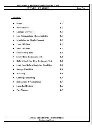
Contents<br />
P.1<br />
P.1<br />
P.2<br />
P.2<br />
P.3<br />
P.4~P.7<br />
P.8<br />
P.8<br />
P.9-P.10<br />
P.11<br />
P.12~P.13<br />
P.14~P.18<br />
P.19~P.20<br />
<br />
YAGEO CORPORATION<br />
Engineering Dept..
1. Scope<br />
<strong>Electrolytic</strong> <strong>Capacitor</strong> <strong>Product</strong> <strong>Specification</strong><br />
<strong>VC</strong> <strong>TYPE</strong> <strong>CZ</strong> <strong>SERIES</strong> 1<br />
Fixed capacitors for use in electronic equipment, Surface Mount Type Aluminum electrolytic<br />
capacitors With non-solid electrolyte.<br />
2. Parts Number<br />
C Z 0 1 6 M 0 0 1 0 R S B - 0405<br />
<br />
Series Name Voltage Code CapacitanDV CapacitanDV Code Package Life Size Case<br />
Voltage Code :<br />
Volt<br />
6.3 10 16 25 35 50<br />
age<br />
Code 006 010 016 025 035 050<br />
Capacitance code :<br />
ToleranDV Code Code Code Code<br />
Capacitance 1.0 2.2 3.3 4.7 6.8 10 22 33<br />
Code 1R00 2R20 3R30 4R70 6R80 0010 0022 0033<br />
Capacitance 47 68 100 220 330 470 1000<br />
Code 0047 0068 0100 0220 0330 0470 1000<br />
Life Code :<br />
Size Code:<br />
S 1000hrs DØ 4 5 6.3 8 8 10<br />
Capacitance Tolerance :<br />
M ±20%<br />
K ±10%<br />
W -5%~+20%<br />
Size Code B C D E F G<br />
YAGEO ELECTRONIC CORPORATION<br />
Engineering Dept..
<strong>Electrolytic</strong> <strong>Capacitor</strong> <strong>Product</strong> <strong>Specification</strong><br />
<strong>VC</strong> <strong>TYPE</strong> <strong>CZ</strong> <strong>SERIES</strong> 2<br />
3.Standard rating<br />
NO Item Ratings<br />
1<br />
Category Temperature<br />
Range<br />
- 40 ~ + 105<br />
2<br />
Rated Working Voltage<br />
Range<br />
6.3 ~ 50 V.DC<br />
3 Capacitance Range 0.1 ~ 220F (120Hz 20)<br />
4 Capacitance Tolerance ± 20 % (120Hz 20)<br />
5<br />
Surge Voltage (V.D.C) R.V 6.3 10 16 25 35 50 63 100<br />
S.V 8 13 20 32 44 63 79 125<br />
4 .Dimensions and Appearance<br />
The Ceiling Indication<br />
(-)<br />
Negative polarity<br />
marking<br />
不 <br />
No marking for the<br />
bi-polar<br />
<br />
Rated<br />
Voltage<br />
量<br />
Capacitance (µF)<br />
列 <br />
Series<br />
Identification<br />
<br />
DATE CODE<br />
1<br />
50 Z<br />
202<br />
Size Code D L A H I W P K<br />
B 4.0 5.4 4.3 5.5 max 1.8 0.65± 0.1 1.0<br />
+0.15<br />
0.35 -0.20<br />
C 5.0 5.4 5.3 6.5 max 2.2 0.65± 0.1 1.5<br />
+0.15<br />
0.35 -0.20<br />
D 6.3 5.4 6.6 7.8 max 2.6 0.65± 0.1 2.2<br />
+0.15<br />
0.35 -0.20<br />
E 8.0 6.2 8.3 9.5 max 3.4 0.65± 0.1 2.2<br />
+0.15<br />
0.35 -0.20<br />
F 8.0 10.2 8.3 10.0 max 3.4 0.90± 0.2 3.1 0.70±0.20<br />
[mm]<br />
G 10.0 10.2 10.3 12.0max 3.5 0.90± 0.2 4.6 0.70±0.20<br />
YAGEO ELECTRONIC CORPORATION<br />
Engineering Dept..
5.Constructions<br />
5-1. Inside Construction<br />
<strong>Electrolytic</strong> <strong>Capacitor</strong> <strong>Product</strong> <strong>Specification</strong><br />
<strong>VC</strong> <strong>TYPE</strong> <strong>CZ</strong> <strong>SERIES</strong> 3<br />
IIR/<br />
RE<br />
<br />
Iso<br />
but<br />
ylen<br />
e<br />
Iso<br />
pre<br />
1 Terminal<br />
ne Rubber / Resin Cure<br />
Parts Materials Parts Materials<br />
Tinned Copper-Clad<br />
Steel wire<br />
5 Separator Manila hemp<br />
2 Isolator Thermo-plastic Resin 6 Anode Foil High Purity Aluminum Foil<br />
3 Aluminum Can Aluminum 7 Cathode Foil Aluminum Foil<br />
4 Sealing Rubber (IIR/RE) 8 Electrolyte <br />
YAGEO ELECTRONIC CORPORATION<br />
Engineering Dept..
<strong>Electrolytic</strong> <strong>Capacitor</strong> <strong>Product</strong> <strong>Specification</strong><br />
<strong>VC</strong> <strong>TYPE</strong> <strong>CZ</strong> <strong>SERIES</strong> 4<br />
6. Performance Characteristics<br />
1<br />
Item Performance Characteristics Test<br />
Leakage<br />
Current<br />
2 Capacitance<br />
3<br />
4<br />
Chara<br />
cteristics<br />
at<br />
High and<br />
Low temperature<br />
Tangent of<br />
Loss<br />
Angie<br />
(tan )<br />
5 Surge<br />
Ste<br />
p<br />
2<br />
Ste<br />
p<br />
4<br />
l=0.01CV or 3A whichever is the<br />
greater.<br />
ILeakage current<br />
CNominal Capacitance<br />
VRated voltage<br />
Within the specified capacitance<br />
tolerance<br />
Series Resistor<br />
Applied Voltage<br />
Measuring<br />
1000±100 Ω<br />
Rated voltage<br />
After 2 minutes<br />
Measuring Frequency 120Hz ± 20%<br />
Measuring Circuit Equivalent series circuit<br />
Measuring Voltage 0.5 ~2.0V.DC<br />
(0.5 V for A.C)<br />
Less than the table l value of page 9 Measuring Frequency 120Hz ± 20 %<br />
Impedance Ratio<br />
Less than the table 2 value of page 9<br />
ratio against step 1.<br />
Leakage Current.<br />
500% of the value of item 6.1<br />
Capacitance Change:<br />
Within ±25% of the value in step 1.<br />
Tangent of Loss Angle (tanδ):<br />
the value of item 6.3.<br />
Leakage Current :<br />
the value of item 6.1.<br />
Capacitance Change:<br />
Within±15% of initial measured value.<br />
Tangent of Loss Angle (tanδ ):<br />
the value of item 6.3.<br />
Appearance:<br />
No significant change can be observed.<br />
Measuring Circuit<br />
Measuring Voltage<br />
Equivalent series circuit<br />
0.5 ~2.0V.DC<br />
(0.5 V for A.C )<br />
Step Test Temperature( ) Time<br />
1 20±2<br />
2<br />
Lower category<br />
temperature ±3<br />
30min.<br />
3 20±2 10~15min.<br />
4<br />
Upper category<br />
temperature ±2<br />
30min.<br />
5 20 ± 2 10~15min.<br />
Impedance should be measured 120Hz ± 10%<br />
Test temperature : 15~35<br />
100±50<br />
Series Protective Resistance : C<br />
R: Protective resistance(k)<br />
C: Capacitance(F )<br />
Test voltage : Surge voltage item 3.5<br />
Applied voltage : 1000 cycles of 30±5 sec<br />
'ON and 5 min30sec”OFF “ .<br />
YAGEO ELECTRONIC CORPORATION<br />
Engineering Dept..
<strong>Electrolytic</strong> <strong>Capacitor</strong> <strong>Product</strong> <strong>Specification</strong><br />
<strong>VC</strong> <strong>TYPE</strong> <strong>CZ</strong> <strong>SERIES</strong> 5<br />
NO Item Performance Characteristics Test<br />
7 Vibration Capacitance<br />
During test measured value shall be<br />
stabilized.(Measured several times<br />
within 30min before completion of<br />
test)<br />
Appearance:<br />
No significant change can be observed.<br />
Capacitance change :<br />
Within ±5% of initial measured value.<br />
Frequency : 10~55Hz (1 minute per cycle)<br />
Total amplitudes : 1.5mm<br />
Direction and duration of vibration :<br />
It is done in the XYZ axis direction<br />
for 2 hours each . with a total of 6 hours.<br />
8 Solder ability More than 95% of the terminal surface<br />
shall be covered with new solder.<br />
Exclude the cross-section of<br />
cutting lead edge<br />
9 Resistance to<br />
Soldering heat<br />
Solder Type:H60A,H60 or H63A (JIS Z3282)<br />
Solder Temperature :235 ±5<br />
Immersing Time :2 ±0.5 sec<br />
Immersing Depth :Dip the terminals for<br />
Approx<br />
0.5~1 mm thick<br />
Flux : Approx 25% rosin (JIS K5902) in<br />
Ethanol(JIS K8101)<br />
Leakage current :<br />
After reflow soldering (item 9 page 13)<br />
the value of item 6.1<br />
The capacitor shall be left at room temperature<br />
Capacitance change :<br />
for before measurement<br />
Within ±15% of initial measured value.<br />
Tangent of Loss Angle (tanδ) :<br />
the value of item 6.3<br />
Appearance :<br />
No significant change can be observed.<br />
10 Solvent<br />
Resistance of the Marking<br />
11 Damp Heat<br />
(steady state)<br />
There shall be no damage end legibly<br />
marked.<br />
marking can be deciphered easily.<br />
Class of Reagent : Isopropyl Alcohol<br />
(JIS K8034) or superior.<br />
Test Temperature :20~25<br />
Immersing time: 30±5 sec<br />
Leakage current :<br />
Test Temperature :40±2<br />
the value of item 6.1<br />
Relative Humidity :90~95%<br />
Capacitance change :<br />
Test Duration :240±8 hours<br />
Within ±5% of initial measured value.<br />
Tangent of Loss Angle (tanδ) :<br />
After subjected to the test. ,the capacitors shall<br />
120% the value of item 6.3 be left for 2 hours at room temperature and<br />
Appearance :<br />
room humidity prior to the measurement.<br />
No significant change can be observed.<br />
YAGEO ELECTRONIC CORPORATION<br />
Engineering Dept..
<strong>Electrolytic</strong> <strong>Capacitor</strong> <strong>Product</strong> <strong>Specification</strong><br />
<strong>VC</strong> <strong>TYPE</strong> <strong>CZ</strong> <strong>SERIES</strong> 6<br />
NO Item Performance Characteristics Test<br />
12 Pressure Relief Pressure relief shall be operated without A.C. Current Method<br />
( Size code any hazardous expulsion or emission of<br />
“ G ”only flame<br />
No emission of gas after 30minutes of<br />
the voltage application also meets the<br />
specification.<br />
Applied Voltage :<br />
A.C. voltage equals to R.V. × 0.7 or<br />
250V(rms) whichever is smaller<br />
Capacitance(F) D.C. Resistance ()<br />
1<br />
1000 100<br />
1 10 100 10<br />
10 100 10 1<br />
100 1000 1 0.1<br />
1000 10000 0.1 .01<br />
10000<br />
When capacitance is over 10000F ,the value<br />
of series resistance equals to the half of the tested<br />
capacitor’s impedance.<br />
Reverse Voltage Method<br />
Nominal Diamether (mm)<br />
D.C. Current (A)<br />
22.4 1 (const)<br />
22.4 10 (const)<br />
YAGEO ELECTRONIC CORPORATION<br />
Engineering Dept..
13 Endurance<br />
<strong>Electrolytic</strong> <strong>Capacitor</strong> <strong>Product</strong> <strong>Specification</strong><br />
<strong>VC</strong> <strong>TYPE</strong> <strong>CZ</strong> <strong>SERIES</strong> 7<br />
NO Item Performance Characteristics Test<br />
Leakage current :<br />
the value of item 6.1<br />
Capacitance change :<br />
Within ±20% of initial measured value.<br />
Ø34 R.V & expanded capacitance range<br />
of 6.3 R.V: ±30%<br />
Tangent of Loss Angle (tanδ) :<br />
200% of the value of item 6.3<br />
Appearance :<br />
No significant change can be observed.<br />
(Ø 3.4R.V. expanded capacitance range )<br />
Test Temperature105±2<br />
Test Duration 1000 (+48) hours<br />
Applied VoltageRated voltage<br />
(Size Code “B ~ G ” )<br />
Test Temperature105 ±2<br />
Test Duration1000 (+72) hours<br />
Applied VoltageRated voltage<br />
After subjected to the test, the capacitors shall<br />
be left at room temperature and room humidity<br />
for 2 hours prior to the measurement<br />
14 Shelf Life<br />
Leakage current :<br />
the value of item 6.1<br />
Capacitance change :<br />
Within ±20% of initial measured value.<br />
Ø34 R.V & expanded capacitance range<br />
of 6.3 R.V: ±30%<br />
Tangent of Loss Angle (tanδ) :<br />
200% of the value of item 6.3<br />
Appearance :<br />
No significant change can be observed.<br />
Test Temperature105±2<br />
Test Duration 1000 (+48) hours<br />
After subjected to the test D.C .rated<br />
voltage shall be applied to the capacitors for<br />
30 minutes as post-test treatment after left<br />
at the room temperature and humidity<br />
for 2 hours prior to the measurement<br />
YAGEO ELECTRONIC CORPORATION<br />
Engineering Dept..
<strong>Electrolytic</strong> <strong>Capacitor</strong> <strong>Product</strong> <strong>Specification</strong><br />
<strong>VC</strong> <strong>TYPE</strong> <strong>CZ</strong> <strong>SERIES</strong> 8<br />
7. Marking<br />
Marking Color : BLACK<br />
(1) Following items shall be marked on the body of <strong>Capacitor</strong><br />
a) Rated Voltage<br />
b) Capacitance<br />
c) Series<br />
d) Date Code<br />
(2) On the Taping Reel<br />
a) Rated VoltageCapacitance<br />
b) MESSRS<br />
c) Part Number<br />
d) Packing Quantity<br />
e) LOT NO<br />
8.Other<br />
Unless otherwise specified, the product shall conform to JIS-C-5140<br />
Table 1. Tangent of Loss Angle [tan]<br />
R.V (V.DC) 6.3 10 16 25 35 50<br />
tan MAX 0.26 0.22 0.16 0.14 0.12 0.12<br />
Table 2. Characteristics at high and low temperature Impedance ratio (at 120Hz)<br />
R.V (V.DC) 6.3 10 16 25 35 50<br />
Z(-25) / Z(20) 2 2 2 2 2 2<br />
Z(-40) / Z(20) 3 3 3 3 3 3<br />
Table 3. Frequency Correction Factor of Rated Ripple Current<br />
Frequency ( Hz )<br />
50 60 120 1k 10k~<br />
coefficient 0.70 0.70 1.0 1.3 1.7<br />
YAGEO ELECTRONIC CORPORATION<br />
Engineering Dept..
<strong>Electrolytic</strong> <strong>Capacitor</strong> <strong>Product</strong> <strong>Specification</strong><br />
<strong>VC</strong> <strong>TYPE</strong> <strong>CZ</strong> <strong>SERIES</strong> 9<br />
9. Reflow Soldering Temperature Profile<br />
After the capacitor is subjected to the specified reflow soldering .(see the temperature profile below), it shall meet the<br />
Condition stated in the page 6, item No 9<br />
Reflow soldering condition<br />
The temperature shall be measured with thermal couple ( type K , Ø 0.1mm ) which shall be placed and fixed on the<br />
top of capacitor body .<br />
Maximum Permissible Reflow Soldering Temperature Profile<br />
YAGEO ELECTRONIC CORPORATION<br />
Engineering Dept..
<strong>Electrolytic</strong> <strong>Capacitor</strong> <strong>Product</strong> <strong>Specification</strong><br />
<strong>VC</strong> <strong>TYPE</strong> <strong>CZ</strong> <strong>SERIES</strong> 10<br />
■ The reflow profile is factory’s specified.<br />
YAGEO ELECTRONIC CORPORATION<br />
Engineering Dept..
<strong>Electrolytic</strong> <strong>Capacitor</strong> <strong>Product</strong> <strong>Specification</strong><br />
<strong>VC</strong> <strong>TYPE</strong> <strong>CZ</strong> <strong>SERIES</strong> 11<br />
10. Taping<br />
10.1 Carrier Tape [mm]<br />
CASE SIZE (∅D mm) W A B P1 F t2<br />
A ∅ 3 12.0 3.4 3.4 8.0 5.5 5.8<br />
B ∅ 4 12.0 4.7 4.7 8.0 5.5 5.8<br />
C ∅ 5 12.0 5.7 5.7 12.0 5.5 5.8<br />
D ∅ 6.3 16.0 7.0 7.0 12.0 7.5 5.8<br />
E ∅ 8×6.2 16.0 8.7 8.7 12.0 7.5 6.8<br />
F ∅ 8×10.2 24.0 8.7 8.7 16.0 11.5 11.0<br />
G ∅ 10×10.2 24.0 10.7 10.7 16.0 11.5 11.0<br />
[mm]<br />
10.2 Reel [mm]<br />
[mm]<br />
Size Code A B C D E F G<br />
W1 14 14 14 18 18 26 26<br />
W2 18 18 18 22 22 30 30<br />
YAGEO ELECTRONIC CORPORATION<br />
Engineering Dept..
<strong>Electrolytic</strong> <strong>Capacitor</strong> <strong>Product</strong> <strong>Specification</strong><br />
<strong>VC</strong> <strong>TYPE</strong> <strong>CZ</strong> <strong>SERIES</strong> 12<br />
11. Details of Carrier Tape<br />
(1)<br />
a. Last reeling empty part of carrier tape shall be more than 10 cm.<br />
b. Leader part of seal tape shall be more than20 cm.<br />
c. First reeling Empty part of carrier tape shall be more than 10 cm.<br />
d. Adhesive tape fixing the end of the leader part shall be approx 10 cm.<br />
(2) Deviation between carrier tape and seal tape<br />
a. Deviation between carrier tape and seal tape shall be less than 0.5 mm.<br />
b .Seal tape shall not cover on the feeding holes more than 0.75 mm.<br />
12. Adhesion Test<br />
Reasonable pulling strength : 0.1 ~ 0.7 N<br />
Pulling speed : 300mm / min<br />
YAGEO ELECTRONIC CORPORATION<br />
Engineering Dept..
<strong>Electrolytic</strong> <strong>Capacitor</strong> <strong>Product</strong> <strong>Specification</strong><br />
<strong>VC</strong> <strong>TYPE</strong> <strong>CZ</strong> <strong>SERIES</strong> 13<br />
13. Packing Style<br />
(1) Carrier tape shall be reeled inside. (seal tape shall be outside)<br />
(2)End of the tape shall be inside to the reel physically as shown in the below figure and leader part of<br />
Seal tape shall not be attached.<br />
14. Dimensions of Outer Carton Box<br />
Dimensions of outer carton box are subject to change without Notice for adjustment to Reel Size.<br />
Inside carton box<br />
Size<br />
A B C D E F G<br />
Code<br />
h 97 97 97 117 117 97 97<br />
Outer carton box<br />
[mm]<br />
Size<br />
A B C D E F G<br />
Code<br />
h 218 218 218 261 261 218 218<br />
15. Packaging Quantity<br />
Size Code ∅ D x L<br />
One Reel<br />
(pcs)<br />
Inside carton box<br />
(reel/Inside carton box)<br />
Outer carton box<br />
(reel/Outer carton box)<br />
A 3x5.4 2000 5 10 20000<br />
B 4x5.4 2000 5 10 20000<br />
C 5x5.4 1000 5 10 10000<br />
D 6.3x5.4 1000 5 10 10000<br />
E 8x6.2 1000 5 10 10000<br />
F 8x10.2 500 3 6 3000<br />
G 10x10.2 500 3 6 3000<br />
Total Quantity<br />
(pcs)<br />
YAGEO ELECTRONIC CORPORATION<br />
Engineering Dept..
<strong>Electrolytic</strong> <strong>Capacitor</strong> <strong>Product</strong> <strong>Specification</strong><br />
<strong>VC</strong> <strong>TYPE</strong> <strong>CZ</strong> <strong>SERIES</strong> 14<br />
1. Circuit Design<br />
1.1 Operating Temperature and Frequency<br />
Electrical parameters for electrolytic capacitors are normally specified at 20temperature and 120 Hz frequency.<br />
These parameters vary with changes in temperature and frequency. Circuit designers should take these changes<br />
into in to consideration<br />
(1) Effects of operating temperature on electrical parameters.<br />
a) At higher temperature. Leakage current and capacitance increase while equivalent series resistance (ESR) decreases.<br />
b) At lower temperature. Leakage current and capacitance decreases while equivalent series resistance (ESR) increase.<br />
(2) Effects of frequency on electrical parameters.<br />
a) At higher frequency. Capacitance and impedance decrease while tanincreases.<br />
b) At lower frequency. Heat generated by ripple current will rise due to an increase in equivalent series<br />
(ESR).resistance<br />
1.2 Operating Temperature and Life Expectancy<br />
(1) Expected life is affected by operating temperature. Generally , each 10 reduction in temperature will double the<br />
expected life. Use capacitors at the lowest possible temperature below the upper category temperature.<br />
(2) If operating temperatures exceed the upper category limit , rapid deterioration of electrical parameter will occur and<br />
irreversible damage will result.<br />
Check for the maximum capacitor operating temperatures including ambient temperature , internal capacitor<br />
temperature rise due to ripple current , and the effects of radiated heat from power transistor ,IC’s or resistors.<br />
Avoid placing components , which could conduct heat to the capacitor from the back side of the circuit board.<br />
(3) The formula for calculating expected life at lower operating temperatures is as follows;<br />
T1T2<br />
10<br />
L2 L1 X 2<br />
L1Guaranteed life (h) at temperature ,T1<br />
L2Expected life (h) at temperature ,T2<br />
T1Upper category temperature ()<br />
T2Actual operating temperature , ambient temperature +temperature rise due to ripple current heating ()<br />
1.3 Common Application Conditions to Avoid<br />
The following misapplication load conditions will cause rapid deterioration of a capacitor’s electrical parameters.<br />
In addition , rapid heating and gas generation within the capacitor can occur , causing the pressure relief vent to<br />
operate and resultant leakage of electrolyte. Under extreme conditions, explosion and fire ignition could result.<br />
The leaked electrolyte is combustible and electrically conductive.<br />
(1) Reverse Voltage<br />
DC capacitors have polarity. Verify correct polarity before insertion. For circuit with changing or uncertain<br />
polarity , use DC bipolar capacitors. DC bipolar capacitors are not suitable for use in AC circuits.<br />
(2) Charge / Discharge Applications<br />
Standard capacitors are not suitable for use in repeating charge / discharge applications. For charge / discharge<br />
applications , consult us with your actual application condition.<br />
(3) Over Voltage<br />
Do not apply voltages exceeding the maximum specified rated voltage. Voltages up to the surge voltage rating are<br />
acceptable for short periods of time. Ensure that the sum of the DC voltage and the superimposed AC ripple<br />
voltage does not exceed the rated voltage.<br />
YAGEO ELECTRONIC CORPORATION<br />
Engineering Dept..
<strong>Electrolytic</strong> <strong>Capacitor</strong> <strong>Product</strong> <strong>Specification</strong><br />
<strong>VC</strong> <strong>TYPE</strong> <strong>CZ</strong> <strong>SERIES</strong> 15<br />
(4) Ripple Current<br />
Do not apply ripple current exceeding the maximum specified value. For high ripple current applications , use a<br />
capacitor designed for high ripple currents. In addition , consult us if the applied ripple current is to be higher than<br />
the maximum specified value. Ensure that rated ripple currents that superimposed on low DC bias voltages do not<br />
cause reverse voltage conditions.<br />
1.4 Using Two or More <strong>Capacitor</strong>s in Series on Parallel<br />
(1) <strong>Capacitor</strong>s Connected in parallel<br />
The circuit resistance can closely approximate the series resistance of the capacitor , causing an imbalance of<br />
ripple current loads within the capacitors. Careful wring methods can minimize the possible application of an<br />
excessive ripple current to a capacitor.<br />
(2) <strong>Capacitor</strong>s Connected in Series<br />
Differences in normal DC leakage current among capacitors can cause voltage imbalances.. The use of voltage<br />
divider shunt resistors with consideration to leakage currents can prevent capacitor voltage imbalance.<br />
1.5 <strong>Capacitor</strong> Mounting Considerations<br />
(1) Double-Sided Circuit Boards<br />
Avoid wiring pattern runs , which pass between the mounted capacitor and the circuit board.<br />
(2) Land / Pad Pattern<br />
The circuit board land / pad pattern size for chip capacitor is specified in the following table.<br />
[mm]<br />
Size / a b C<br />
dimensio<br />
n<br />
B (∅4) 1.0 2.5 1.6<br />
C (∅5) 1.5 2.8 1.6<br />
D (∅6.3) 1.8 3.2 1.6<br />
E (∅8x6.2) 2.2 4.0 1.6<br />
F (∅8x10.2) 3.1 4.0 2.0<br />
G (∅10x10.2) 4.6 4.1 2.0<br />
(3) Clearance for Case Mounted Pressure Relief<br />
capacitors with case mounted pressure relief require sufficient clearance to allow for proper pressure relief<br />
operation.<br />
The minimum clearance are dependent on capacitor diameters as follows.( ∅10mm)<br />
(4) Wiring Near the Pressure Relief<br />
Avoid locating high voltage or high current wiring or circuit board paths above pressure relief. Flammable ,<br />
high temperature gas that exceeds 100 may be released which could dissolve the wire insulation and ignite.<br />
(5) Circuit Board Patterns Under the <strong>Capacitor</strong><br />
Avoid circuit board runs under the capacitor , as an electrical short can occur due to an electrolyte leakage.<br />
1.6 Electrical Isolation of the capacitor<br />
Completely isolate the capacitor as follows.<br />
Between the cathode and the case and between the anode terminal and other circuit paths.<br />
1.7 <strong>Capacitor</strong> Sleeve<br />
The laminate coating is intended for marking and identification purposes and is not meant to electrically insulate the<br />
capacitor.<br />
YAGEO ELECTRONIC CORPORATION<br />
Engineering Dept..
<strong>Electrolytic</strong> <strong>Capacitor</strong> <strong>Product</strong> <strong>Specification</strong><br />
<strong>VC</strong> <strong>TYPE</strong> <strong>CZ</strong> <strong>SERIES</strong> 16<br />
2. <strong>Capacitor</strong> Handling Techniques<br />
2.1 Considerations Before Using<br />
(1) <strong>Capacitor</strong> have a finite life. Do not reuse or recycle capacitors from used equipment.<br />
(2) Transient recovery voltage may be generated in the capacitor due to dielectric absorption. If required , this voltage<br />
can be discharged with a resistor with a value of about 1 K.<br />
(3) <strong>Capacitor</strong>s stored for a long period of time may exhibit an increase in leakage current. This can be corrected by<br />
gradually applying rated voltage in series with a resistor of approximately 1 K.<br />
(4) If capacitors are dropped , they can be damaged mechanically or electrically. Avoid using dropped capacitors.<br />
(5) Dented or crushed capacitors should not be used. The seal integrity can be damaged and loss of electrolyte /<br />
shortened life can result.<br />
2.2 <strong>Capacitor</strong> Insertion<br />
(1) Verify the correct capacitance and rated voltage of the capacitor.<br />
(2) Verify the correct polarity of the capacitor before insertion.<br />
(3) Verify the correct hole spacing and land pattern size before insertion to avoid stress on the terminals.<br />
(4) For chip type capacitors , excessive mounting pressure can cause high leakage current , short circuit , or<br />
disconnection.<br />
2.3 Manual Soldering<br />
(1) Observe temperature and time soldering specifications or do not exceed temperatures of 300for 3 seconds<br />
or less.<br />
(2) If a soldered capacitor must be removed and reinserted , avoid excessive stress on the capacitor leads..<br />
(3) Avoid physical contacts between the tip of the soldering iron and capacitors to prevent or capacitor failure<br />
2.4 Reflow Soldering<br />
(1) For reflow , use a thermal conduction system such as infrared radiation (IR) or hot blast.<br />
Vapor heat transfer system (VPS) are not recommended.<br />
(2) Observe proper soldering conditions (temperature , time , etc.).Do not exceed the specified limits.<br />
(3) Reflow should be performed one time. Consult us for additional reflow restrictions.<br />
The temperature on <strong>Capacitor</strong> top shall be measured by using thermal couple that is fixed firmly by epoxy glue.<br />
2.5 <strong>Capacitor</strong> Handling after Soldering<br />
(1) Avoid moving the capacitor after soldering to prevent excessive stress on the lead wires where they enter the seal.<br />
(2) Do not use the capacitor as a handle when moving the circuit board assembly.<br />
(3) Avoid striking the capacitor after assembly to prevent failure due to excessive shock.<br />
YAGEO ELECTRONIC CORPORATION<br />
Engineering Dept..
<strong>Electrolytic</strong> <strong>Capacitor</strong> <strong>Product</strong> <strong>Specification</strong><br />
<strong>VC</strong> <strong>TYPE</strong> <strong>CZ</strong> <strong>SERIES</strong> 17<br />
2.6 Circuit Board Cleaning<br />
(1) Circuit boards can be immersed or ultrasonically cleaned using suitable cleaning solvents for up to 5 minutes and up<br />
to 60 maximum temperatures. The boards should be thoroughly rinsed and dried.<br />
The use of ozone depleting cleaning agents is not recommended for the purpose of protecting our environment.<br />
(2) Avoid using the following solvent groups unless specifically allowed for in the specification.<br />
․Halogenated cleaning solventsexcept for solvent resistant capacitor types. halogenated solvent can permeate the<br />
seal and cause internal capacitor corrosion and failure. For solvent resistant capacitors , carefully follow the<br />
temperature and time requirements based on the specification . 1-1-1 trichloroethane should never be used on any<br />
aluminum electrolytic capacitor.<br />
․Alkaline solvent<br />
․Petroleum based solvents<br />
․Xylene<br />
․Acetone<br />
could react and dissolve the aluminum case.<br />
deterioration of the rubber seal could result.<br />
deterioration of the rubber seal could result.<br />
removal of the ink markings on the vinyl sleeve could result.<br />
(3) A thorough drying after cleaning is required to remove residual cleaning solvent that may be trapped between the<br />
capacitor and the circuit board. Avoid drying temperatures , which exceed the upper category temperature of the<br />
capacitor..<br />
(4) Monitor the contamination levels of the cleaning solvents during use in terms of electrical conductivity , PH ,specific<br />
gravity or water content. Chlorine levels can rise with contamination and adversely affect the performance of the<br />
capacitor.<br />
Please consult us if you are not certain about acceptable cleaning solvents or cleaning methods..<br />
2.7 Mount Adhesives and Coating Agents<br />
When using mounting adhesives or coating agents to control humidity. Avoid using materials containing<br />
halogenated solvents. Also , avoid the use of chloroprene based polymers.<br />
After applying adhesives or coating , dry thoroughly to prevent residual solvent from being trapped between the<br />
capacitor and the circuit board.<br />
3.Precautions for using capacitors<br />
3.1 Environmental Conditions<br />
<strong>Capacitor</strong>s should not be stored or used in the following environments.<br />
(1) Exposure to temperature above the upper category or below the lower category temperature of the capacitor.<br />
(2) Direct contact with water , salt , or oil.<br />
(3) High humidity conditions where eater could condense on the capacitor.<br />
(4) Exposure to toxic gases such as hydrogen sulfide , sulfuric acid , chlorine , chlorine compound , bromine ,<br />
bromine compound or ammonia.<br />
(5) Exposure to ozone , radiations ,or ultraviolet rays.<br />
(6) Vibration and shock conditions exceeding specified requirements.<br />
YAGEO ELECTRONIC CORPORATION<br />
Engineering Dept..
<strong>Electrolytic</strong> <strong>Capacitor</strong> <strong>Product</strong> <strong>Specification</strong><br />
<strong>VC</strong> <strong>TYPE</strong> <strong>CZ</strong> <strong>SERIES</strong> 18<br />
3.2 Electrical Procedures<br />
(1) Avoid touching the terminals of a capacitor as a possible electric shock could result. The exposed aluminum<br />
case is not insulated and could also cause electric shock if touched.<br />
(2) Avoid short circuiting the area between the capacitor terminals with conductive materials including liquids<br />
such as acids or alkaline solutions.<br />
4. Emergency Procedures<br />
(1) If the pressure relief of the capacitor operates , immediately turn off the equipment and disconnect from the<br />
power source. This will minimize additional damage caused by the vaporizing electrolyte.<br />
(2) Avoid contact with the escaping electrolyte gas , which can exceed 100 temperature.<br />
If electrolyte or gas enters the eye , immediately flush the eye with large amounts of water.<br />
If electrolyte or gas is ingested by mouth , gargle with water.<br />
If electrolyte contacts the skin , wash with soap and water.<br />
5. Long Term Storage<br />
Leakage current of a capacitor increases with long storage times. The aluminum oxide film deteriorates as a<br />
function of temperature and time. If used without reconditioning , an abnormally high current will be required to<br />
restore the oxide film.<br />
This current surge could cause the circuit or the capacitor to fail.<br />
After one year. A capacitor should be reconditioned by applying the rated voltage in series with a 1000,<br />
current limiting resistor for a time period of 30 minutes.<br />
5.1 Environmental Conditions<br />
(1) Exposure to temperature above the upper category or below the lower category temperature of the capacitor.<br />
(2) Direct contact with water , salt , or oil.<br />
(3) High humidity conditions where eater could condense on the capacitor.<br />
(4) Exposure to toxic gases such as hydrogen sulfide , sulfuric acid , chlorine , nitric acid chlorine compound ,<br />
bromine ,bromine compound or ammonia.<br />
(5) Exposure to ozone , radiations ,or ultraviolet rays.<br />
(6) Vibration and shock conditions exceeding specified requirements.<br />
6. <strong>Capacitor</strong> Disposal<br />
When disposing of capacitors , use one of the following methods.<br />
(1) Incinerate after crushing the capacitor or puncturing the can wall (to prevent explosion due to internal<br />
pressure rise)<br />
(2) Dispose of as solid waste.<br />
YAGEO ELECTRONIC CORPORATION<br />
Engineering Dept..
Parts lists<br />
Size<br />
Code<br />
<strong>Electrolytic</strong> <strong>Capacitor</strong> <strong>Product</strong> <strong>Specification</strong><br />
<strong>VC</strong> <strong>TYPE</strong> <strong>CZ</strong> <strong>SERIES</strong> 19<br />
Rated Ripple<br />
Part N0<br />
Tangent of Loss Current mA<br />
R.V Cap<br />
Angle<br />
r.m.s<br />
V.DC (F)<br />
(tan) MAX (100KHz 105)<br />
MAX<br />
B <strong>CZ</strong>004M4R70RSB-0405 4 4.7 0.35 60 4.0<br />
B <strong>CZ</strong>004M6R80RSB-0405 4 6.8 0.35 60 4.0<br />
B <strong>CZ</strong>004M0010RSB-0405 4 10 0.35 60 4.0<br />
B <strong>CZ</strong>004M0022RSB-0405 4 22 0.35 60 4.0<br />
B <strong>CZ</strong>004M0033RSB-0405 4 33 0.35 60 4.0<br />
B <strong>CZ</strong>004M0047RSB-0405 4 47 0.35 60 4.0<br />
B <strong>CZ</strong>004M0068RSB-0405 4 68 0.35 60 4.0<br />
C <strong>CZ</strong>004M0100RSC-0505 4 100 0.35 95 3.0<br />
D <strong>CZ</strong>004M0150RSD-0605 4 150 0.35 140 2.6<br />
D <strong>CZ</strong>004M0220RSD-0605 4 220 0.35 140 2.6<br />
Z()(max)<br />
100KHz,20C<br />
B <strong>CZ</strong>006M0022RSB-0405 6.3 22 0.26 60 4.0<br />
C <strong>CZ</strong>006M0033RSC-0505 6.3 33 0.26 95 2.6<br />
C <strong>CZ</strong>006M0047RSC-0505 6.3 47 0.26 95 2.6<br />
D <strong>CZ</strong>006M0068RSD-0605 6.3 68 0.26 140 1.3<br />
D <strong>CZ</strong>006M0100RSD-0605 6.3 100 0.26 140 1.3<br />
E <strong>CZ</strong>006M0150RSE-0806 6.3 150 0.35 230 0.8<br />
E <strong>CZ</strong>006M0220RSE-0806 6.3 220 0.35 230 0.8<br />
F <strong>CZ</strong>006M0330RSF-0810 6.3 330 0.35 450 0.5<br />
G <strong>CZ</strong>006M0470RSG-1010 6.3 470 0.35 670 0.3<br />
G <strong>CZ</strong>006M1000RSG-1010 6.3 1000 0.35 670 0.3<br />
B <strong>CZ</strong>010M0010RSB-0405 10 10 0.22 60 4.0<br />
C <strong>CZ</strong>010M0022RSC-0505 10 22 0.22 95 2.6<br />
C <strong>CZ</strong>010M0033RSC-0505 10 33 0.22 95 2.6<br />
D <strong>CZ</strong>010M0047RSD-0605 10 47 0.22 95 1.3<br />
D <strong>CZ</strong>010M0068RSD-0605 10 68 0.22 140 1.3<br />
D <strong>CZ</strong>010M0100RSD-0605 10 100 0.22 140 1.3<br />
E <strong>CZ</strong>010M0150RSE-0806 10 150 0.26 230 0.8<br />
E <strong>CZ</strong>010M0220RSE-0806 10 220 0.26 230 0.8<br />
F <strong>CZ</strong>010M0330RSF-0810 10 330 0.26 450 0.5<br />
G <strong>CZ</strong>010M0470RSG-1010 10 470 0.26 670 0.3<br />
G <strong>CZ</strong>010M1000RSG-1010 10 1000 0.26 670 0.3<br />
B <strong>CZ</strong>016M4R70RSB-0405 16 4.7 0.16 60 4.0<br />
B <strong>CZ</strong>016M6R80RSB-0405 16 6.8 0.16 60 4.0<br />
B <strong>CZ</strong>016M0010RSB-0405 16 10 0.16 60 4.0<br />
C <strong>CZ</strong>016M0022RSC-0505 16 22 0.16 95 2.6<br />
C <strong>CZ</strong>016M0033RSC-0505 16 33 0.16 95 2.6<br />
D <strong>CZ</strong>016M0047RSD-0605 16 47 0.16 140 1.3<br />
E <strong>CZ</strong>016M0068RSE-0806 16 68 0.20 230 0.8<br />
E <strong>CZ</strong>016M0100RSE-0806 16 100 0.20 230 0.8<br />
G <strong>CZ</strong>016M0150RSG-1010 16 150 0.20 450 0.5<br />
G <strong>CZ</strong>016M0220RSG-1010 16 220 0.20 450 0.5<br />
YAGEO ELECTRONIC CORPORATION<br />
Engineering Dept..
Parts lists<br />
Size<br />
Code<br />
<strong>Electrolytic</strong> <strong>Capacitor</strong> <strong>Product</strong> <strong>Specification</strong><br />
<strong>VC</strong> <strong>TYPE</strong> <strong>CZ</strong> <strong>SERIES</strong> 20<br />
Rated Ripple<br />
Part N0<br />
Tangent of Loss Current mA<br />
R.V Cap<br />
Angle<br />
r.m.s<br />
V.DC (F)<br />
(tan) MAX (100KHz 105)<br />
MAX<br />
G <strong>CZ</strong>016M0330RSG-1010 16 330 0.20 670 0.3<br />
G <strong>CZ</strong>016M0470RSG-1010 16 470 0.20 670 0.3<br />
Z()(max)<br />
100KHz,20C<br />
B <strong>CZ</strong>025M4R70RSB-0405 25 4.7 0.14 60 4.0<br />
B <strong>CZ</strong>025M6R80RSB-0405 25 6.8 0.14 60 4.0<br />
C <strong>CZ</strong>025M0010RSC-0505 25 10 0.14 95 2.6<br />
D <strong>CZ</strong>025M0022RSD-0605 25 22 0.14 140 1.3<br />
D <strong>CZ</strong>025M0033RSD-0605 25 33 0.14 140 1.3<br />
D <strong>CZ</strong>025M0047RSD-0605 25 47 0.14 140 1.3<br />
F <strong>CZ</strong>025M0068RSF-0810 25 68 0.16 450 0.5<br />
F <strong>CZ</strong>025M0100RSF-0810 25 100 0.16 450 0.5<br />
G <strong>CZ</strong>025M0150RSG-1010 25 150 0.16 670 0.3<br />
G <strong>CZ</strong>025M0220RSG-1010 25 220 0.16 670 0.3<br />
B <strong>CZ</strong>035M1R00RSB-0405 35 1 0.12 60 4.0<br />
B <strong>CZ</strong>035M2R20RSB-0405 35 2.2 0.12 60 4.0<br />
B <strong>CZ</strong>035M3R30RSB-0405 35 3.3 0.12 60 4.0<br />
B <strong>CZ</strong>035M4R70RSB-0405 35 4.7 0.12 60 4.0<br />
C <strong>CZ</strong>035M6R80RSC-0505 35 6.8 0.12 95 2.6<br />
C <strong>CZ</strong>035M0010RSC-0505 35 10 0.12 95 2.6<br />
D <strong>CZ</strong>035M0022RSD-0605 35 22 0.12 140 1.3<br />
E <strong>CZ</strong>035M0033RSE-0806 35 33 0.14 230 0.8<br />
H <strong>CZ</strong>035M0047RSH-0607 35 47 0.14 200 1.0<br />
E <strong>CZ</strong>035M0047RSE-0806 35 47 0.14 230 0.8<br />
F <strong>CZ</strong>035M0068RSF-0810 35 68 0.14 450 0.5<br />
G <strong>CZ</strong>035M0100RSG-1010 35 100 0.14 670 0.3<br />
G <strong>CZ</strong>035M0150ESG-1010 35 150 0.14 670 0.3<br />
G <strong>CZ</strong>035M0220RSG-1010 35 220 0.14 670 0.3<br />
B <strong>CZ</strong>050M0R10RSB-0405 50 0.1 0.12 60 5.0<br />
B <strong>CZ</strong>050M0R22RSB-0405 50 0.22 0.12 60 5.0<br />
B <strong>CZ</strong>050M0R33RSB-0405 50 0.33 0.12 60 5.0<br />
B <strong>CZ</strong>050M0R47RSB-0405 50 0.47 0.12 60 5.0<br />
B <strong>CZ</strong>050M1R00RSB-0405 50 1 0.12 60 5.0<br />
B <strong>CZ</strong>050M2R20RSB-0405 50 2.2 0.12 60 5.0<br />
B <strong>CZ</strong>050M3R30RSB-0405 50 3.3 0.12 60 5.0<br />
C <strong>CZ</strong>050M4R70RSC-0505 50 4.7 0.12 95 4.0<br />
D <strong>CZ</strong>050M6R80RSD-0605 50 6.8 0.12 140 2.6<br />
D <strong>CZ</strong>050M0010RSD-0605 50 10 0.12 140 2.6<br />
E <strong>CZ</strong>050M0022RSE-0806 50 22 0.12 230 1.3<br />
F <strong>CZ</strong>050M0033RSF-0810 50 33 0.12 300 1.1<br />
G <strong>CZ</strong>050M0047RSG-1010 50 47 0.12 670 0.8<br />
G <strong>CZ</strong>050M0068RSG-1010 50 68 0.12 670 0.8<br />
G <strong>CZ</strong>050M0100RSG-1010 50 100 0.12 670 0.8<br />
YAGEO ELECTRONIC CORPORATION<br />
Engineering Dept..
Yageo Corporation<br />
3F, 233-1, Pao Chiao Rd.,<br />
Hsin Tien, Taipei, Taiwn<br />
Tel: 886.2.2917.7555<br />
Fax: 886.2.2917.3789