Electrolytic Capacitor Product Specification VC TYPE CZ SERIES ...
Electrolytic Capacitor Product Specification VC TYPE CZ SERIES ...
Electrolytic Capacitor Product Specification VC TYPE CZ SERIES ...

You also want an ePaper? Increase the reach of your titles
YUMPU automatically turns print PDFs into web optimized ePapers that Google loves.
<strong>Electrolytic</strong> <strong>Capacitor</strong> <strong>Product</strong> <strong>Specification</strong><br />
<strong>VC</strong> <strong>TYPE</strong> <strong>CZ</strong> <strong>SERIES</strong> 15<br />
(4) Ripple Current<br />
Do not apply ripple current exceeding the maximum specified value. For high ripple current applications , use a<br />
capacitor designed for high ripple currents. In addition , consult us if the applied ripple current is to be higher than<br />
the maximum specified value. Ensure that rated ripple currents that superimposed on low DC bias voltages do not<br />
cause reverse voltage conditions.<br />
1.4 Using Two or More <strong>Capacitor</strong>s in Series on Parallel<br />
(1) <strong>Capacitor</strong>s Connected in parallel<br />
The circuit resistance can closely approximate the series resistance of the capacitor , causing an imbalance of<br />
ripple current loads within the capacitors. Careful wring methods can minimize the possible application of an<br />
excessive ripple current to a capacitor.<br />
(2) <strong>Capacitor</strong>s Connected in Series<br />
Differences in normal DC leakage current among capacitors can cause voltage imbalances.. The use of voltage<br />
divider shunt resistors with consideration to leakage currents can prevent capacitor voltage imbalance.<br />
1.5 <strong>Capacitor</strong> Mounting Considerations<br />
(1) Double-Sided Circuit Boards<br />
Avoid wiring pattern runs , which pass between the mounted capacitor and the circuit board.<br />
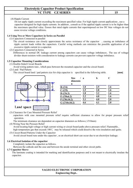
(2) Land / Pad Pattern<br />
The circuit board land / pad pattern size for chip capacitor is specified in the following table.<br />
[mm]<br />
Size / a b C<br />
dimensio<br />
n<br />
B (∅4) 1.0 2.5 1.6<br />
C (∅5) 1.5 2.8 1.6<br />
D (∅6.3) 1.8 3.2 1.6<br />
E (∅8x6.2) 2.2 4.0 1.6<br />
F (∅8x10.2) 3.1 4.0 2.0<br />
G (∅10x10.2) 4.6 4.1 2.0<br />
(3) Clearance for Case Mounted Pressure Relief<br />
capacitors with case mounted pressure relief require sufficient clearance to allow for proper pressure relief<br />
operation.<br />
The minimum clearance are dependent on capacitor diameters as follows.( ∅10mm)<br />
(4) Wiring Near the Pressure Relief<br />
Avoid locating high voltage or high current wiring or circuit board paths above pressure relief. Flammable ,<br />
high temperature gas that exceeds 100 may be released which could dissolve the wire insulation and ignite.<br />
(5) Circuit Board Patterns Under the <strong>Capacitor</strong><br />
Avoid circuit board runs under the capacitor , as an electrical short can occur due to an electrolyte leakage.<br />
1.6 Electrical Isolation of the capacitor<br />
Completely isolate the capacitor as follows.<br />
Between the cathode and the case and between the anode terminal and other circuit paths.<br />
1.7 <strong>Capacitor</strong> Sleeve<br />
The laminate coating is intended for marking and identification purposes and is not meant to electrically insulate the<br />
capacitor.<br />
YAGEO ELECTRONIC CORPORATION<br />
Engineering Dept..