ODU MAC
ODU MAC
ODU MAC

You also want an ePaper? Increase the reach of your titles
YUMPU automatically turns print PDFs into web optimized ePapers that Google loves.
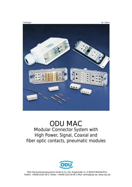
Catalogue No. 1004-d<strong>ODU</strong> <strong>MAC</strong>Modular Connector System withHigh Power, Signal, Coaxial andfiber optic contacts, pneumatic modules<strong>ODU</strong> Steckverbindungssysteme GmbH & Co. KG, Pregelstraße 11, D-84453 Mühldorf/InnTelefon: +49/86 31/61 56-0, Telefax: +49/86 31/61 56 49, E-Mail: zentral@odu.de, www.odu.de
<strong>ODU</strong> <strong>MAC</strong>ContentsPage<strong>ODU</strong> <strong>MAC</strong> Product Description 4<strong>ODU</strong>-Springwire Contact Principle 5<strong>ODU</strong> <strong>MAC</strong> Modules: Insulation Bodies, Contacts, Technical Data 8 - 29<strong>ODU</strong> <strong>MAC</strong> Aluminum Frame 30 - 34<strong>ODU</strong> <strong>MAC</strong> DIN Housing 35 - 45<strong>ODU</strong> <strong>MAC</strong> Crimp Tools 46 - 55Technical Information 56 - 59<strong>ODU</strong> <strong>MAC</strong> Application Examples 60 - 63Technical Article 64 - 71<strong>ODU</strong> Steckverbindungssysteme GmbH & Co. KG, Pregelstr. 11, D-84453 Mühldorf/Inn, Tel. +49/86 31/61 56-0, Fax +49/86 31/61 56 49, www.odu.de Page 3
<strong>ODU</strong> <strong>MAC</strong>Product description:The <strong>ODU</strong> <strong>MAC</strong> connector system consists of a variety of customizable rugged frames, plastic insulationbodies (modules) with many of insert patterns, and crimpable, removable contacts for high currents (power),low currents (signal), and RF-signals. Modules can be arranged in different patterns in the frame accordingto application. Unit spacing is 2.54 mm (.100") or a multiple thereof. Guide pins and guide bushingsprevent misconnections and provide easy alignment for accurate mating.<strong>ODU</strong> <strong>MAC</strong> in Alu FrameThis frame has two end pieces and two rails withguiding and mounting hardware. The socket part(receptacle) is generally fixed while the pin part(plug) is typically mounted floating. This frame canaccept between 3 to 60 units with a width of 2.54mm each. For example, if 10 position modulesare used, a connector with max. 600 AWG 22contacts can be assembled.<strong>ODU</strong> <strong>MAC</strong> in DIN Housingwith Locking Latch<strong>ODU</strong> <strong>MAC</strong> in DIN housing with locking latch isavailable in four sizes. Size I accepts 10 modules(2.54 mm ea.) while Size IV accommodates up to34 models (2.54 mm ea.). Size IV can have max.340 contacts AWG 22.<strong>ODU</strong> <strong>MAC</strong> in DIN Housingwith Locking SpindleTo make the standard DIN housing with lockinglatch more user-friendly, a quick connect-disconnectlocking spindle was developed. As an option,the DIN housings are offered with a precisionlocking spindle. The locking spindle provides verysmooth locking and unlocking of the connectorwith a single twist.The locking spindle system is especially designedfor high number of connects and disconnects. Theprecision of the spindle allows more than 5,000mating cycles.Page 4<strong>ODU</strong> Steckverbindungssysteme GmbH & Co. KG, Pregelstr. 11, D-84453 Mühldorf/Inn, Tel. +49/86 31/61 56-0, Fax +49/86 31/61 56 49, www.odu.de
<strong>ODU</strong> <strong>MAC</strong>The Concept of Springtac SpringwireContacts.The springwire contact is the invention of Otto Dunkel.The Figure shows a Springtac socket and solid pin.The socket has a multitude of preformed springwires.The springwires are parallel to the plugging direction.They form a flexible cage, with one end fixed at thebottom of the socket, the other end free to move.The springwires are independent from each other andmake contact with the surface of the pin.This arrangement creates in the mated condition analmost constant normal pressure over the entire contactsurface of the pin. A springwire socket for a 1.02 mmdia. (AWG 20) pin has about 19 springwires. Thenumber of springwires increases with the size of thecontact. This results in many contact points betweenpin and socket, creating a large contact area for excellentcurrent transmission. Springtac contacts are availablefrom 0.6 mm dia. to more than 50 mm dia. Theycan be supplied with solder, crimp, or threaded studtermination.Contact retention in a connector insulation body is viamilitary-style contact clips.The outstanding advantages of <strong>ODU</strong> Springtaccontacts are:❏❏❏❏❏❏❏Very high contact reliabilityLow contact resistanceHigh current carrying capabilityHigh resistance to vibrationLow mating and demating forceHigh number of mating cyclesLong service lifeKontaktdrahtOberflächenveredelungBuchsenwandBerührungsflächeKontaktstift<strong>ODU</strong> Steckverbindungssysteme GmbH & Co. KG, Pregelstr. 11, D-84453 Mühldorf/Inn, Tel. +49/86 31/61 56-0, Fax +49/86 31/61 56 49, www.odu.de Page 5
<strong>ODU</strong> <strong>MAC</strong>The ModulesThe insulation bodies (modules) are presently availablein 23 different versions (sizes as well as number ofcontacts per module). Figure beside shows a fewexamples. Insulation bodies are made of glass-filledthermoplastic polyester, UL-94 0 rated. Unit widthof a module is 2.54 mm. Modules come in multiplesof unit width.The crimped contacts snap into the cavities from therear and can be removed in seconds with standardcontact removal tools. The modules are locked into theconnector frame with locking ridges in grooves.Contact Retentionthe Clip PrincipleClipFigure beside shows a contact inside a module.Contacts are inserted from the rear. Retentionclips snap over the shoulder of the contact andhold the contact in place. Removal of thecontacts is very simple with the use of standardcontact removal tools. Although this type ofretention clips andinsulation bodies require expensive precisionproduction methods, the military-style contactretention system is a very desirable approach tocontact retention. It offers significant advantagesover fixed contacts. Higher operating voltagesfor each module can be achieved by leavingadjacentcontact cavities empty.Page 6<strong>ODU</strong> Steckverbindungssysteme GmbH & Co. KG, Pregelstr. 11, D-84453 Mühldorf/Inn, Tel. +49/86 31/61 56-0, Fax +49/86 31/61 56 49, www.odu.de
<strong>ODU</strong> <strong>MAC</strong>For your notes<strong>ODU</strong> Steckverbindungssysteme GmbH & Co. KG, Pregelstr. 11, D-84453 Mühldorf/Inn, Tel. +49/86 31/61 56-0, Fax +49/86 31/61 56 49, www.odu.de Page 7
ModulesModule, 10 Positionsfor turned contactsSpacer (Blank)(Dummy Module)Current Information acc. VDE 1)Reference Voltage: 50 V 20 VRated Surge Voltage: 1500 V 1500 VDegree of Pollution: 2 3Current Information acc. MIL 2)Reference Voltage:500 VTest Voltage:1500 VTotal Mating Force (Average): 7,7 N (27 oz.)/ModuleTotal Demating Force (Average): 7,1 N (25 oz.)/ModuleContact Diameter: 0,76 mm (.030”)Contact Finish:Materials:Insulation Body:Contact Body:Contact Spring:Operating Temperature:0,75 µm Au over 1,25 µm Ni(30 µ” Au over 50 µ” Ni)Glass-filled thermoplastic(Polyester), UL-94 V0 ratedCU-AloyCuBe-40 ºC up to +125ºCIsolierkörper Module, 10 Positions 10polig Zwischenstück Spacer (Blank)Dummy Blindpfropfen ContactPlugging Steckseite Direction1910,12,542,54(1 Unit)8(by (bei solder-in Einlöttechnik) version)2,54(1 (1 Unit) Einheit)= 22,86 =3030XRemoval Einstellmaß Tool I für8-Punkt-QuetschzangeRemoval Tool ICurrent load only for single contacts. For multiplecontacts derate acc. to VDE 0298.Insulation BodySpacerRemoval Tool IRemoval Tool IIPin Contact*Grd. Pin Contact*Socket Contact*Pin ContactGrd. Pin ContactSocket ContactPin ContactGrd. Pin ContactSocket ContactDummy Contact* Non magnetic on requestPart Number.611 122 110 923 000611 122 111 923 000087 170 361 000 000087 611 001 001 000180 361 000 307 000180 381 000 307 000170 361 700 207 000180 540 000 307 000180 570 000 307 000170 540 700 207 000180 850 000 307 000180 851 000 307 000170 850 700 207 000021 341 123 300 000TerminationAWG/mm2AWG 22AWG 22AWG 22AWG 24/28AWG 24/28AWG 24/28PCBSolder PinØ 0,76max. Current(A)5,05,05,01,51,51,55,05,05,0Crimp Instructions see page 46/47ContactResistance (mΩ)average3,83,83,83,83,83,83,83,83,8Removal Tool II1) see page 562) see page 59Page 8<strong>ODU</strong> Steckverbindungssysteme GmbH & Co. KG, Pregelstr. 11, D-84453 Mühldorf/Inn, Tel. +49/86 31/61 56-0, Fax +49/86 31/61 56 49, www.odu.de
ModulesModule, 10 Positionsfor stamped contactsCurrent Information acc. VDE 1)Reference Voltage: 32 V 10 VRated Surge Voltage: 1500 V 1500 VDegree of Pollution: 2 3Current Information acc. MIL 2)Reference Voltage:450 VTest Voltage:1350 VSocketStiftTotal Mating Force (Average): 7,4 N (26 oz.)/ModuleTotal Demating Force (Average): 6,5 N (23 oz.)/ModuleContact Diameter: 0,7 mm (.028”)Contact Finish on termination area: 3 µm Sn (120 µ” Sn)Contact Finish on contact area: 0,75 µm Au (30 µ” Au)Materials:Insulation Body:Glass-filled thermoplastic(Polyester), UL-94 V0 ratedContact: CuSn 6Operating Temperature:-40 ºC up to +125ºCModule, Isolierkörper 10 Positions 10poligSocket Buchse (Crimp (Crimpausführung)termination)Isolierkörper Module, 10 Positions 10poligStift Pin (Crimpausführung)termination)Zwischenstück Spacer20,511,510,12,5422,862,541 Einheit (1 Unit)302,54(1 (1 Einheit) Unit)3,2 ±0,320,5Ø 0,7BuchseSocketS0,70,7 StiftPin S0,70,718,1 17Ø 0,72,541 (1 Einheit Unit)Insulation Body Socket (Crimp)Insulation Body Pin (Crimp)Insulation Body Socket (Print)SpacerPin ContactSocket ContactPin ContactSocket ContactPart Number.610 158 110 923 000611 158 110 923 000610 158 010 923 000611 122 111 923 000186 080 103 535 1..*176 082 103 535 1..*186 080 103 535 2..*176 082 103 535 2..*TerminationAWG/mm226/2826/2822/2422/24max. Current(A)3,53,54,54,5ContactResistance (mΩ)average3,83,83,83,8Contacts not removeable1) see page 562) see page 59* Packaging units for Crimpversion.51 = 500 pcs on tape.52 = 900 pcs on tape.54 = 5 000 pcs on tape.55 = 10 000 pcs on tape.50 = 20 000 pcs on tapeCrimp Instructions see page 46/47The 10 position modules with turned andstamped contacts are not mating compatible.<strong>ODU</strong> Steckverbindungssysteme GmbH & Co. KG, Pregelstr. 11, D-84453 Mühldorf/Inn, Tel. +49/86 31/61 56-0, Fax +49/86 31/61 56 49, www.odu.de Page 9
ModulesModule, for Print, Wire Wrap Terminationand IDC-connectors10 Positions6 PositionsCurrent Information acc. VDE 1)Reference Voltage: 50 V 20 VRated Surge Voltage: 1500 V 1500 VDegree of Pollution: 2 3Current Information acc. MIL 2)Reference Voltage:500 VTest Voltage:1500 VTotal Mating Force (Average): 7,7 N (27 oz.)/ModuleTotal Demating Force (Average): 7,1 N (25 oz.)/ModuleContact Diameter: 0,76 mm (.030”)Contact Finish:Materials:Insulation Body:0,75 µm Au over 1,25 µm Ni(30 µ” Au over 50 µ” Ni)Glass-filled thermoplastic(Polyester), UL-94 V0 ratedContact Body:CU-AloyContact Spring:CuBeOperating Temperature: -20 ºC up to +105 ºCPin Insert22,862,54Ø 0,64 Ø 0,649152,542,54(1 Unit)Socket Insert= 22,86 =308 150,64 0,64Pin InsertSocket Insert10 Positions611 146 010 923 000610 146 010 923 0006 Positions611 146 006 923 000610 146 006 923 000Print••Terminationfor IDCconnectors••WireWrap–•1) see page 562) see page 59Page 10<strong>ODU</strong> Steckverbindungssysteme GmbH & Co. KG, Pregelstr. 11, D-84453 Mühldorf/Inn, Tel. +49/86 31/61 56-0, Fax +49/86 31/61 56 49, www.odu.de
ModulesModule 6 PositionsSpacer (Blank)(Dummy Module)Current Information acc. VDE 1)Reference Voltage: 200 V 63 VRated Surge Voltage: 2500 V 2500 VDegree of Pollution: 2 3Current Information acc. MIL 2)Reference Voltage:850 VTest Voltage:2550 VTotal Mating Force (Average): 6,5 N (23 oz.)/ModuleTotal Demating Force (Average): 6,0 N (22 oz.)/ModuleContact Diameter: 1,02 mm (.040”)Contact Finish:Materials:Insulation Body:Contact Body:Contact Spring:0,75 µm Au over 1,25 µm Ni(30 µ” Au over 50 µ” Ni)Glass-filled thermoplastic(Polyester), UL-94 V0 ratedCU-AloyCuBeOperating Temperature:-40°C up to +125°CModule, 6 Positions Spacer (Blank) Dummy ContactPlugging Steckseite Direction1910,13,815,08(2 Units8(by (bei solder-in Einlöttechnik) version)5,08(2 Units)= 19,05 =30Current load only for single contacts. For multiple contactsderate acc. to VDE 0298.30XRemoval Tool IEinstellmaß für8-Punkt-QuetschzangeInsulation BodySpacerRemoval Tool IRemoval Tool IIPin Contact*Grd. Pin Contact*Socket Contact*Pin ContactGrd. Pin ContactSocket ContactPin ContactGrd. Pin ContactSocket ContactDummy ContactPart Number.611 123 106 923 000611 123 111 923 000087 170 362 000 000087 611 001 001 000180 362 000 307 000180 382 000 307 000170 362 700 207 000180 544 000 307 000180 574 000 307 000170 544 700 207 000180 818 000 307 000180 819 000 307 000170 818 700 207 000021 341 124 300 000TerminationAWG/mm2AWG 20/22AWG 20/22AWG 20/22AWG 24/28AWG 24/28AWG 24/28PCBSolder PinØ 1,0max. Current(A)6,06,06,02,02,02,06,06,06,0ContactResistance (mΩ)average2,12,12,12,12,12,12,12,12,1Removal Tool II1) see page 562) see page 59Crimp Instructions see page 46/47* Non magnetic on request<strong>ODU</strong> Steckverbindungssysteme GmbH & Co. KG, Pregelstr. 11, D-84453 Mühldorf/Inn, Tel. +49/86 31/61 56-0, Fax +49/86 31/61 56 49, www.odu.de Page 11
ModulesModule 14 PositionsSpacer (Blank)(Dummy module)Current Information acc. VDE 1)Reference Voltage: 160 V 32 VRated Surge Voltage: 2500 V 2500 VDegree of Pollution: 2 3Current Information acc. MIL 2)Reference Voltage:950 VTest Voltage:2850 VTotal Mating Force (Average): 14,2 N (51 oz.)/ModuleTotal Demating Force (Average): 13,5 N (49 oz.)/ModuleContact Diameter: 1,02 mm (.040”)Contact Finish:0,75 µm Au over 1,25 µm Ni(30 µ” Au over 50 µ” Ni)Materials:Insulation Body:Glass-filled thermoplastic(Polyester), UL-94 V0 ratedContact Body:CU-AloyContact Spring:CuBeOperating Temperature: -40°C up to +125°CModule, Isolierkörper 14 Positions 14polig Zwischenstück BlindpfropfenPlugging Steckseite DirectionSpacer (Blank)Dummy Contact1910,13,53,657,62(3 Units)8(by (bei solder-in Einlöttechnik) versions)7,62(3 Units)X= 21,9 =3030Einstellmaß für8-Punkt-QuetschzangeRemoval Tool ICurrent load only for single contacts.For multiple contacts derate acc. to VDE 0298.Insulation BodySpacerRemoval Tool IRemoval Tool IIPin Contact*Grd. Pin Contact*Socket Contact*Pin ContactGrd. Pin ContactSocket ContactPin ContactGrd. Pin ContactSocket ContactDummy ContactPart Number.611 130 114 923 000611 130 111 923 000087 170 362 000 000087 611 001 001 000180 362 000 307 000180 382 000 307 000170 362 700 207 000180 544 000 307 000180 574 000 307 000170 544 700 207 000180 818 000 307 000180 819 000 307 000170 818 700 207 000021 341 124 300 000TerminationAWG/mm2AWG 20/22AWG 20/22AWG 20/22AWG 24/28AWG 24/28AWG 24/28PCBSolder PinØ 1,02max. Current(A)6,06,06,02,02,02,06,06,06,0ContactResistance (mΩ)average2,12,12,12,12,12,12,12,12,1Removal Tool II1) see page 562) see page 59Crimp Instructions see page 46/47* Non magnetic on requestPage 12<strong>ODU</strong> Steckverbindungssysteme GmbH & Co. KG, Pregelstr. 11, D-84453 Mühldorf/Inn, Tel. +49/86 31/61 56-0, Fax +49/86 31/61 56 49, www.odu.de
ModulesModule 5 PositionsSpacer (Blank)(Dummy module)Current Information acc. VDE 1)Reference Voltage: 250 V 40 VRated Surge Voltage: 2500 V 2500 VDegree of Pollution: 2 3Current Information acc. MIL 2)Reference Voltage:750 VTest Voltage:2250 VTotal Mating Force (Average): 10,2 N (37 oz.)/ModuleTotal Demating Force (Average): 8,5 N (31 oz.)/ModuleContact Diameter: 1,5 mm (.059”)Contact Finish:Contact Body:0,75 µm Au over 1,25 µm Ni(30 µ” Au over 50 µ” Ni)Contact Springs:6 µm Ag (240 µ” Ag)Materials:Insulation Body:Glass-filled thermoplastic(Polyester), UL-94 V0 ratedContact Body:CU-AloyContact Spring:CuSnOperating Temperature: -40°C up to +125°CModule, Isolierkörper 5 Positions 5polig Zwischenstück BlindpfropfenPlugging Steckseite DirectionSpacer (Blank)Dummy Contact1912,15,085,08(2 Units)8(by (bei solder-in Einlöttechnik) version)5,08(2 Units)= 20,32 =3030Removal Tool XIEinstellmaß für8-Punkt-QuetschzangeCurrent load only for single contacts.For multiple contacts derate acc. to VDE 0298.Insulation Body 5poligSpacerRemoval Tool IRemoval Tool IIPin Contact*Grd. Pin Contact*Socket Contact*Pin ContactGrd. Pin ContactSocket ContactPin ContactGrd. Pin ContactSocket ContactPin ContactGrd. Pin ContactSocket ContactPin ContactGrd. Pin ContactSocket ContactPin ContactGrd. Pin ContactSocket ContactDummy ContactPart Number.611 124 105 923 000611 124 111 923 000087 170 137 000 000087 611 001 001 000180 363 000 307 000180 383 000 307 000170 363 700 201 000180 543 000 307 000180 573 000 307 000170 543 700 201 000180 545 000 307 000180 575 000 307 000170 545 700 201 000180 541 000 307 000180 571 000 307 000170 541 700 201 000180 857 000 307 000180 856 000 307 000170 857 700 201 000180 539 000 307 000180 569 000 307 000170 539 700 201 000021 341 125 300 000TerminationAWG/mm 21,5 mm 21,5 mm 21,5 mm 2AWG 16AWG 16AWG 161 mm 21 mm 21 mm 2AWG 20/22AWG 20AWG 20/22AWG 24/28AWG 24/28AWG 24/28PCBSolder PinØ 1,5max. Current(A)18,018,018,015,015,015,013,013,013,07,57,57,52,02,02,018,018,018,0ContactResistance (mΩ)average0,950,950,950,950,950,950,950,950,950,950,950,950,950,950,950,950,950,95Removal Tool II1) see page 562) see page 59Crimp Instructions see page 46/47* Non magnetic on request<strong>ODU</strong> Steckverbindungssysteme GmbH & Co. KG, Pregelstr. 11, D-84453 Mühldorf/Inn, Tel. +49/86 31/61 56-0, Fax +49/86 31/61 56 49, www.odu.de Page 13
ModulesModule 4 PositionsModule, 4 PositionsPlugging Steckseite DirectionSpacer (Blank)(Dummy module)Current Information acc. VDE 1)Reference Voltage: 320 V 160 VRated Surge Voltage: 2500 V 2500 VDegree of Pollution: 2 3Current Information acc. MIL 2)Reference Voltage:1100 VTest Voltage:3300 VTotal Mating Force (Average): 19,5 N (70 oz.)/ModuleTotal Demating Force (Average): 17,0 N (61 oz.)/ModuleContact Diameter: 2,41 mm (.095”)Contact Finish:6 µm Ag (240 µ” Ag)Materials:Insulation Body:Glass-filled thermoplastic(Polyester), UL-94 V0 ratedContact Body:CU-AloyContact Spring:CuSnOperating Temperature: -40°C up to +125°CSpacer (Blank)Dummy Contact1912,16,357,62(3 Units)8(by (bei solder-in Einlöttechnik) version)7,62(3 Units)= 19,05 =3030Removal Tool ICurrent load only for single contacts.For multiple contacts derate acc. to VDE 0298.other contact Ø on requestInsulation Body 4poligSpacerRemoval Tool IRemoval Tool IIPin ContactGrd. Pin ContactSocket ContactPin Contact*Grd. Pin Contact*Socket Contact*Pin ContactGrd. Pin ContactSocket ContactPin ContactGrd. Pin ContactSocket ContactPin ContactGrd. Pin ContactSocket ContactPin ContactGrd. Pin ContactSocket ContactDummy Contact* Non magnetic on requestPart Number.611 126 104 923 000611 126 111 923 000087 170 365 000 000087 611 001 001 000180 365 000 301 000180 385 000 301 000170 365 100 201 000180 910 000 301 000180 911 000 301 000170 910 100 201 000182 607 000 301 000182 604 000 301 000172 604 100 201 000182 606 000 301 000182 603 000 301 000172 603 100 201 000182 608 000 301 000182 605 000 301 000172 605 100 201 000180 820 000 301 000180 821 000 301 000170 820 100 201 000021 341 127 300 000TerminationAWG/mm 2AWG 12AWG 12AWG 122,5 mm 22,5 mm 22,5 mm 21,5 mm 21,5 mm 21,5 mm 21,0 mm 21,0 mm 21,0 mm 2AWG 20/22AWG 20/22AWG 20/22PCBSolder PinØ 2,4max. Current(A)23,023,023,023,023,023,018,018,018,013,013,013,07,57,57,523,023,023,0ContactResistance (mΩ)average0,410,410,411,001,001,001,001,001,001,001,001,001,001,001,000,410,410,41Removal Tool II1) see page 562) see page 59Crimp Instructions see page 46/47Page 14<strong>ODU</strong> Steckverbindungssysteme GmbH & Co. KG, Pregelstr. 11, D-84453 Mühldorf/Inn, Tel. +49/86 31/61 56-0, Fax +49/86 31/61 56 49, www.odu.de
ModulesModule 3 PositionsSpacer (Blank)(Dummy module)Current Information acc. VDE 1)Reference Voltage: 250 V 100 VRated Surge Voltage: 2500 V 2500 VDegree of Pollution: 2 3Current Information acc. MIL 2)Reference Voltage:1200 VTest Voltage:3600 VTotal Mating Force (Average): 18,5 N (67 oz.)/ModuleTotal Demating Force (Average): 16,0 N (58 oz.)/ModuleContact Diameter: 3,0 mm (.118”)Contact Finish:6 µm Ag (240 µ” Ag)Materials:Insulation Body:Glass-filled thermoplastic(Polyester), UL-94 V0 ratedContact Body:CU-AloyContact Spring:CuSnOperating Temperature: -40°C up to +125°CModule, 3 PositionsPlugging Steckseite DirectionSpacer (Blank)Dummy Contact1912,17,627,62(3 Units)7,62(3 Units)= 15,24 =3030Removal Tool ICurrent load only for single contacts.For multiple contacts derate acc. to VDE 0298.other contact Ø on requestRemoval Tool IIInsulation Body 3poligSpacerRemoval Tool IRemoval Tool IIPin ContactGrd. Pin ContactSocket ContactPin ContactGrd. Pin ContactSocket ContactPin ContactGrd. Pin ContactSocket ContactPin ContactGrd. Pin ContactSocket ContactPin ContactGrd. Pin ContactSocket ContactDummy ContactPart Number.611 127 103 923 000611 127 111 923 000087 170 136 000 000087 611 001 001 000180 366 000 301 000180 386 000 301 000172 366 100 201 000180 546 000 301 000180 576 000 301 000170 546 100 201 000182 582 000 301 000182 583 000 301 000172 582 100 201 000182 584 000 301 000182 585 000 301 000172 584 100 201 000182 586 000 301 000182 587 000 301 000172 586 100 201 000021 341 128 300 000Terminationmm24,0 mm 24,0 mm 24,0 mm 22,5 mm 22,5 mm 22,5 mm 21,5 mm 21,5 mm 21,5 mm 21,0 mm 21,0 mm 21,0 mm 2AWG 20/22AWG 20/22AWG 20/22max. Current(A)3030302626261818181313137.57.57.5ContactResistance (mΩ)average0,300,300,300,300,300,301,001,001,001,001,001,001,001,001,001) see page 562) see page 59Crimp Instructions see page 46/47<strong>ODU</strong> Steckverbindungssysteme GmbH & Co. KG, Pregelstr. 11, D-84453 Mühldorf/Inn, Tel. +49/86 31/61 56-0, Fax +49/86 31/61 56 49, www.odu.de Page 15
ModulesModule 3 PositionsSpacer (Blank)(Dummy Module)Current Information acc. VDE 1)Reference Voltage: 250 V 160 VRated Surge Voltage: 2500 V 2500 VDegree of Pollution: 2 3Current Information acc. MIL 2)Reference Voltage:1250 VTest Voltage:3750 VTotal Mating Force (Average): 18,5 N (67 oz.)/ModuleTotal Demating Force (Average): 16,0 N (58 oz.)/ModuleContact Diameter: 4,0 mm (.157”)Contact Finish:6 µm Ag (240 µ” Ag)Materials:Insulation Body:Glass-filled thermoplastic(Polyester), UL-94 V0 ratedContact Body:CU-AloyContact Spring:CuSnOperating Temperature: -40°C up to +125°CModule, 3 PositionsPlugging Steckseite DirectionSpacer (Blank)Dummy Contact318,8912,7(5 Units)12,7(5 Units)17= 17,78 =3030Removal Tool ICurrent load only for single contacts.For multiple contacts derate acc. to VDE 0298.Removal Tool IIInsulation Body 3poligSpacerRemoval Tool IRemoval Tool IIPin ContactGrd. Pin ContactSocket ContactDummy ContactPart Number.611 128 103 923 000611 128 111 923 000087 170 367 000 000087 611 001 001 000180 367 000 301 000180 387 000 301 000170 367 100 201 000021 341 129 923 000Terminationmm 2max. Current(A)6,0 mm 2 406,0 mm 26,0 mm 24040ContactResistance (mΩ)average0,280,280,281) see page 562) see page 59Crimp Instructions see page 46/47Page 16<strong>ODU</strong> Steckverbindungssysteme GmbH & Co. KG, Pregelstr. 11, D-84453 Mühldorf/Inn, Tel. +49/86 31/61 56-0, Fax +49/86 31/61 56 49, www.odu.de
ModulesModule 2 PositionsSpacer (Blank)(Dummy Module)Current Information acc. VDE 1)Reference Voltage: 250 V 160 VRated Surge Voltage: 2500 V 2500 VDegree of Pollution: 2 3Current Information acc. MIL 2)Reference Voltage:1250 VTest Voltage:3750 VTotal Mating Force (Average): 22,0 N (79 oz.)/ModuleTotal Demating Force (Average): 18,0 N (65 oz.)/ModuleContact Diameter: 5,0 mm (.197”)Contact Finish:6 µm Ag (240 µ” Ag)Materials:Insulation Body:Glass-filled thermoplastic(Polyester), UL-94 V0 ratedContact Body:CU-AloyContact Spring:CuSnOperating Temperature: -40°C up to +125°CModule, 2 PositionsPlugging Steckseite DirectionSpacer (Blank)Dummy Contact12,7(5 Units)12,7(5 Units)311712,73030Removal Tool ICurrent load only for single contacts.For multiple contacts derate acc. to VDE 0298.Removal Tool IIInsulation Body 2poligSpacerRemoval Tool IPin ContactGrd. Pin ContactSocket ContactPin ContactGrd. Pin ContactSocket ContactDummy ContactPart Number.611 129 102 923 000611 129 111 923 000087 170 391 000 000180 490 000 301 000180 491 000 301 000170 490 100 201 000180 369 000 301 000180 389 000 301 000170 369 100 201 000021 341 130 923 000Terminationmm 2max. Current(A)10,0 mm 2 6010,0 mm 2 6010,0 mm 2 604,0 mm 2 344,0 mm 24,0 mm 23434ContactResistance (mΩ)average0,210,210,210,210,210,211) see page 562) see page 59Crimp Instructions see page 46/47<strong>ODU</strong> Steckverbindungssysteme GmbH & Co. KG, Pregelstr. 11, D-84453 Mühldorf/Inn, Tel. +49/86 31/61 56-0, Fax +49/86 31/61 56 49, www.odu.de Page 17
ModulesModule 4 Positionsfor high voltage contactsSocketModuleSocket, 4 PositionsPinModulePin, 4 PositionsCurrent Information acc. VDE 1)Reference Voltage: 2500 V 1000 VRated Surge Voltage: 10000 V 8000 VDegree of Pollution: 2 3Current Information acc. MIL 2)Reference Voltage:2500 VTest Voltage:7500 VTotal Mating Force (Average): 10,2 N (36 oz.)/ModuleTotal Demating Force (Average): 8,5 N (30 oz.)/ModuleContact Diameter: 1,5 mm (.039”)Contact Finish:0,75 µm Au over 1,25 µm Ni(30 µ” Au over 50 µ” Ni)Materials:Insulation Body:Glass-filled thermoplastic(Polyester), UL-94 V0 ratedContact Body:CU-AloyContact Spring:CuSnOperating Temperature: -40°C up to +125°C30,230,2 6Spacer (Blank)12,16,218,6Insulation Body (Socket)Insulation Body (Pin)SpacerRemoval Tool IRemoval Tool IIPin Contact*Grd. Pin Contact*Socket Contact*Pin ContactGrd. Pin ContactSocket ContactPin ContactGrd. Pin ContactSocket ContactPin ContactGrd. Pin ContactSocket ContactPin ContactGrd. Pin ContactSocket ContactPin ContactGrd. Pin ContactSocket ContactDummy Contact* Non magnetic on request7,62(3 3 Units) EinheitenPart Number.610 159 104 923 000611 159 104 923 000611 126 111 923 000087 170 137 000 000087 611 001 001 000180 363 000 307 000180 383 000 307 000170 363 700 201 000180 543 000 307 000180 573 000 307 000170 543 700 201 000180 545 000 307 000180 575 000 307 000170 545 700 201 000180 541 000 307 000180 571 000 307 000170 541 700 201 000180 857 000 307 000180 856 000 307 000170 857 700 201 000180 539 000 307 000180 569 000 307 000170 539 700 201 000021 341 125 300 0006,2TerminationAWG/mm 21,5 mm 21,5 mm 21,5 mm 2AWG 16AWG 16AWG 161 mm 21 mm 21 mm 2AWG 20/22AWG 20AWG 20/22AWG 24/28AWG 24/28AWG 24/28PCBSolder-PinØ 1,518,6max. Current(A)18,018,018,015,015,015,013,013,013,07,57,57,52,02,02,018,018,018,07,62(3 Units) 3 EinheitenContactResistance (mΩ)average0,950,950,950,950,950,950,950,950,950,950,950,950,950,950,950,950,950,9530Dummy Contact7,62(3 Units) 3 EinheitenRemoval Tool IRemoval Tool II1) see page 562) see page 59Crimp Instructions see page 46/47Page 18<strong>ODU</strong> Steckverbindungssysteme GmbH & Co. KG, Pregelstr. 11, D-84453 Mühldorf/Inn, Tel. +49/86 31/61 56-0, Fax +49/86 31/61 56 49, www.odu.de
ModulesModule 4 Positionsfor 50 Ω Coax-Contactsnon magnetic with the clip principleFrequency range:Current Information acc. MIL 2)Reference Voltage:Test Voltage:Insulation resistance:Total Mating Force (Average):Total Demating Force (Average):Materials:Insulation Body:Contact Body:Contact Spring-center contact:Contact Spring-outer contactContact Finish:Pin, center contact:Pin, outer contact:Socket, center contact:Socket, outer contact:Operating Temperature:0-1,2 GHz350 V1050 V>100 G Ω17 N (60 oz.)/Module14 N (49 oz.)/ModuleGlass-filled thermoplastic(Polyester), UL-94 V0 ratedCU-AloyCuSnCuBe0,8 µm Au over 2 µm white bronze(32 µ” Au over 50 µ” white bronze)-40°C up to +125°CModule, 4 PositionsSpacer (Blank)Insertion Loss1912,10-0,0519,056,35Strip off length22,577,623 (3 Einheiten Units)30Removal Tool I7,623 Einheiten (3 Units)VSWR * S21 in dB-0,1-0,15-0,2-0,250 0,25 0,5 0,75 1 1,25 1,5Frequency in GHzVSWR *1,41,31,2Removal Tool II1,1PinSocket10 0,25 0,5 0,75 1 1,25 1,5Ø 4,612,1 8,312,130,9 22,6Ø 3Ø 4,6Frequency in GHz*Voltage standing wave ratioInsulation BodySpacerRemoval Tool IRemoval Tool IIPin Contact straightPin Contact straightSocket Contact straightSocket Contact straightPart Number611 149 104 923 000611 126 111 923 000087 170 365 000 000087 611 001 001 000122 120 001 257 000122 120 003 257 000122 120 002 257 000122 120 004 257 000Cableimpedance (Ω)50505050CableRG178 / RG196RG174 / RG188 / RG316(75 Ω: RG179, RG187)RG178, RG196RG174 / RG188 / RG316(75 Ω: RG179, RG187)2) see page 59Crimp DiesPart Number082 000 039 101 000082 000 039 102 000082 000 039 101 000082 000 039 102 000Crimp Instructions see page 46/47<strong>ODU</strong> Steckverbindungssysteme GmbH & Co. KG, Pregelstr. 11, D-84453 Mühldorf/Inn, Tel. +49/86 31/61 56-0, Fax +49/86 31/61 56 49, www.odu.de Page 19
ModulesModule 2 Positionsfor 50 Ω Coax-Contactsin the clip principleModule, Pin and Socket, 2 PositionsPlugging Steckseite Direction3011,82412,7(5 Units)Frequency range:0-2,5 GHzCurrent Information acc. MIL 2)Reference Voltage:400 VTest Voltage:1200 VInsulation resistance:>100 G ΩTotal Mating Force (Average): 9 N (32 oz.)/ModuleTotal Demating Force (Average): 7,5 N (26 oz.)/ModuleMaterials:Insulation Body:Glass-filled thermoplastic(Polyester), UL-94 V0 ratedContact Body:Cu-AloyContact Spring:CuSnContact Finish:Pin, center contact:0,75 µm Au over 1,25 µm Ni(30 µ” Au over 50 µ” Ni)Pin, outer contact:6 µm Ni (240 µ” Ni)Socket, center contact: Springs 0,75 µm Au over 1,25 µm Ni(30 µ” Au over 50 µ” Ni)Socket, outer contact: Springs 0,75 µm Au over 1,25 µm Ni(30 µ” Au over 50 µ” Ni)Operating Temperature: -40°C up to +125°CStrip off length22,57Cable terminationHigh frequency characteristics of the 50 Ω Coaxial ContactsVSWR S21 in dB0,0-0,1-0,2-0,3Insertion Loss-0,40,0 1,0 2,0 3,0Frequency in GHz1,81,61,4VSWR *1,2Center contact solderedOuter contact soldered or crimpedInsulation BodySpacerDummy ContactRemoval ToolPin Contact straightPin Contact straightPin Contact straightPin Contact straightPin Contact straightSocket Contact straightSocket Contact straightSocket Contact straightSocket Contact straightSocket Contact straightCrimp tool for EMI Sleeve2) see page 59Removal ToolPart Number.611 152 102 923 000611 129 111 923 000021 341 177 300 000087 170 391 000 000122 346 001 207 000122 346 003 207 000122 346 005 207 000122 346 007 207 000122 346 009 207 000122 346 002 207 000122 346 004 207 000122 346 006 207 000122 346 008 207 000122 346 010 207 000080 000 039 000 000CableImpedance (Ω)50505050505050505050CableRG178 / RG196RG174 / RG188 / RG 316RG122 (2YCY 0.4/2.5-75 Ω)RG58RG223RG178 / RG196RG174 / RG188 / RG 316RG122 (2YCY 0.4/2.5-75 Ω)RG58RG2231,00,0 1,0 2,0 3,0Frequency in GHz*Voltage standing wave ratioCrimp DiesPart Number082 000 039 101 000082 000 039 102 000082 000 039 104 000082 000 039 106 000082 000 039 106 000082 000 039 101 000082 000 039 102 000082 000 039 104 000082 000 039 106 000082 000 039 106 000Page 20<strong>ODU</strong> Steckverbindungssysteme GmbH & Co. KG, Pregelstr. 11, D-84453 Mühldorf/Inn, Tel. +49/86 31/61 56-0, Fax +49/86 31/61 56 49, www.odu.de
ModulesModule 2 Positionsfor 50 Ω Coax-Contactsin the clip principle - SMA TerminationModule, Pin and Socket, 2 PositionsPlugging Steckseite DirectionFrequency range:0-9 GHzCurrent Information acc. MIL 2)Reference Voltage:350 VTest Voltage:1050 VInsulation resistance:>100 G ΩTotal Mating Force (Average): 9 N (32 oz.)/ModuleTotal Demating Force (Average): 7,5 N (26 oz.)/ModuleMaterials:Insulation Body:Glass-filled thermoplastic(Polyester), UL-94 V0 ratedContact Body:Cu-AloyContact Spring:CuSnContact Finish:Pin, center contact:0,75 µm Au over 1,25 µm Ni(30 µ” Au over 50 µ” Ni)Pin, outer contact:6 µm Ni (240 µ” Ni)Socket, center contact: Springs 0,75 µm Au over 1,25 µm Ni(30 µ” Au over 50 µ” Ni)Socket, outer contact: Springs 0,75 µm Au over 1,25 µm Ni(30 µ” Au over 50 µ” Ni)Operating Temperature: -40°C up to +125°C0High frequency characteristics of the 50 Ω Coaxial ContactsInsertion Loss-0,0512,72411,830SMA-Termination(5 Units)VSWR S21 in dB-0,1-0,15-0,20 1 2 3 4 5 6 7 8 9 10Frequency in GHzVSWR *1,41,31,21,1Removal Tool10 1 2 3 4 5 6 7 8 9 10Frequency in GHz*Voltage standing wave ratioInsulation BodySpacerDummy ContactRemoval ToolPin Contact straightSocket Contact straightPart Number611 152 102 923 000611 129 111 923 000021 341 177 300 000087 122 349 000 000122 349 001 207 000122 349 002 207 000TerminationStyleSMAS<strong>MAC</strong>ableImpedance (Ω)50502) see page 59<strong>ODU</strong> Steckverbindungssysteme GmbH & Co. KG, Pregelstr. 11, D-84453 Mühldorf/Inn, Tel. +49/86 31/61 56-0, Fax +49/86 31/61 56 49, www.odu.de Page 21
ModulesModule 2 Positionsfor 50 Ω Coax-Contactsin the clip principle - high voltageFrequency range:Current Information acc. MIL 2)Reference Voltage:Test Voltage:Insulation resistance:Total Mating Force (Average):Total Demating Force (Average):Materials:Insulation Body:Contact:Surface:Operating Temperature:0 - 0,25 GHz850 V2600 V>100 G Ω9 N (32 oz.)/Module7,5 N(26 oz.)/ModuleGlass-filled thermoplastic(Polyester), UL-94 V0 ratedCU-Aloy2 µm white bronze + 0,8 µm Au(80 µ” white bronze + 32 µ” Au)-40°C up to +125°CModule, Pin and Socket, 2 Positions0,0High frequency characteristics of the 50 Ω Coaxial ContactsInsertion LossPlugging Steckseite Direction-0,13011,82412,7(5 Units)Removal ToolStrip off lengthVSWR S21 in dB-0,2-0,3-0,40,0 0,1 0,2 0,3 0,4 0,5Frequency in GHz1,81,61,4VSWR *51,29,52PinØ 6,5Ø 9,5Ø 9,512,9 8,812,938,2 29,4Socket1,00,0 0,1 0,2 0,3 0,4 0,5Frequency in GHz*Voltage standing wave ratioCenter contact - solderedOuter contact - soldered or crimpedInsulation Body 2 PositionsSpacerDummy contactRemoval ToolPin Contact*Pin Contact*Pin Contact*Socket Contact*Socket Contact*Socket Contact** Contacts non magneticPart Number611 155 102 923 000611 129 111 923 000021 341 177 300 000087 170 391 000 000122 126 001 257 000122 126 003 257 000122 126 009 257 000122 126 002 257 000122 126 004 257 000122 126 010 257 0002) see page 59Coax CableRG178 / RG196RG174 / RG188 / RG 316RG223RG178 / RG196RG174 / RG188 / RG 316RG223Page 22<strong>ODU</strong> Steckverbindungssysteme GmbH & Co. KG, Pregelstr. 11, D-84453 Mühldorf/Inn, Tel. +49/86 31/61 56-0, Fax +49/86 31/61 56 49, www.odu.de
ModulesModule 2 Positionsfor 50 Ω Coax-Contacts(old version)*Module, Pin and Socket, 2 PositionsPlugging Steckseite DirectionFrequency range:0-2,5 GHzCurrent Information acc. MIL 2)Reference Voltage:400 VTest Voltage:1200 VInsulation resistance:>100 G ΩTotal Mating Force (Average): 9 N (32 oz.)/ModuleTotal Demating Force (Average): 7,5 N (26 oz.)/ModuleMaterials:Insulation Body:Glass-filled thermoplastic(Polyester), UL-94 V0 ratedContact Body:Cu-AloyContact Spring:CuSnContact Finish:Pin, center contact:0,75 µm Au over 1,25 µm Ni(30 µ” Au over 50 µ” Ni)Pin, outer contact:6 µm Ni (240 µ” Ni)Socket, center contact: Springs 0,75 µm Au over 1,25 µm Ni(30 µ” Au over 50 µ” Ni)Socket, outer contact: Springs 0,75 µm Au over 1,25 µm Ni(30 µ” Au over 50 µ” Ni)Operating Temperature: -40°C up to +125°C13High frequency characteristics of the 50 Ω Coaxial Contacts0,0Insertion Loss-0,111,830Strip off length22,5712,7(5 Units)Cable terminationVSWR S21 in dB-0,2-0,3-0,40,0 1,0 2,0 3,0Frequency in GHzVSWR **1,81,61,41,21,00,0 1,0 2,0 3,0Frequency in GHzinner conductor solderedouter conductor soldered or crimped* only for replacement** Voltage standing wave ratioInsulation Body 2poligPin Contact straightPin Contact straightPin Contact straightPin Contact straightSocket Contact straightSocket Contact straightSocket Contact straightSocket Contact straightCrimp Tool for EMI Sleeve2) see page 59Part Number.611 141 102 923 000122 331 001 207 000122 333 001 207 000122 335 001 207 000122 337 001 207 000122 331 002 207 000122 333 002 207 000122 335 002 207 000122 337 002 207 000080 000 039 000 000CableImpedance (Ω)5050505050505050Cable (Examples)RG178 / RG196RG174 / RG188 / RG316RG 122 (2YCY 0,4/2,5 -75 Ω)RG58RG178 / RG196RG174 / RG188 / RG316RG 122 (2YCY 0,4/2,5 -75 Ω)RG58Crimp DiesPart Number082 000 039 101 000082 000 039 102 000082 000 039 104 000082 000 039 106 000082 000 039 101 000082 000 039 102 000082 000 039 104 000082 000 039 106 000<strong>ODU</strong> Steckverbindungssysteme GmbH & Co. KG, Pregelstr. 11, D-84453 Mühldorf/Inn, Tel. +49/86 31/61 56-0, Fax +49/86 31/61 56 49, www.odu.de Page 23
ModulesModule 2 Positionsfor 75 Ω Coax-Contacts in the clipprincipleModule, Pin and Socket, 2 PositionsFrequency range:0-2GHzCurrent Information acc. MIL 2)Reference Voltage:475 VTest Voltage:1425 VInsulation resistance:>100 G ΩTotal Mating Force (Average): 9 N (32 oz.)/ModuleTotal Demating Force (Average): 7,5 N (26 oz.)/ModuleMaterials:Insulation Body:Glass-filled thermoplastic(Polyester), UL-94 V0 ratedContact Body:Cu-AloyContact Spring:CuSnContact Finish:Pin, center contact:0,75 µm Au over 1,25 µm Ni(30 µ” Au over 50 µ” Ni)Pin, outer contact:6 µm Ni (240 µ” Ni)Socket, center contact: Springs 0,75 µm Au over 1,25 µm Ni(30 µ” Au over 50 µ” Ni)Socket, outer contact: Springs 0,75 µm Au over 1,25 µm Ni(30 µ” Au over 50 µ” Ni)Operating Temperature: -40°C up to +125°C24High frequency characteristics of the 75 Ω Coaxial Contacts0.00Insertion Loss-0.0512,7(5 Units)11,8 ± 0,0330Strip off length22,5Removal ToolCable terminationVSWR S21 in dB-0.10-0.15-0.200.0 0.5 1.0 1.5 2.0 2.5 3.01.51.41.31.2Frequency in GHzVSWR*71.11.00.0 0.5 1.0 1.5 2.0 2.5 3.0Frequency in GHzinner conductor solderedouter conductor soldered or crimped*Voltage standing wave ratioInsulation BodySpacerDummy ContactRemoval ToolPin Contact straightPin Contact straightPin Contact straightSocket Contact straightSocket Contact straightSocket Contact straightCrimp tool for EMI SleevePart Number.611 155 102 923 000611 129 111 923 000021 341 179 923 000087 170 391 000 000122 348 003 207 000122 348 007 207 000122 348 009 207 000122 348 004 207 000122 348 008 207 000122 348 010 207 000080 000 039 000 000CableImpedance (Ω)757575757575RG179 / RG187G 03233 (H+S)RG59RG179 / RG187G 03233 (H+S)RG59Cable (Examples)Crimp DiesPart Number082 000 039 102 000082 000 039 106 000082 000 039 109 000082 000 039 102 000082 000 039 106 000082 000 039 109 0002) see page 59Page 24<strong>ODU</strong> Steckverbindungssysteme GmbH & Co. KG, Pregelstr. 11, D-84453 Mühldorf/Inn, Tel. +49/86 31/61 56-0, Fax +49/86 31/61 56 49, www.odu.de
Module for 75 Ω Coax-Contacts(old version)*Frequency range:0-500 MHzCurrent Information acc. MIL 2)Reference Voltage:650 VTest Voltage:1950 VInsulation resistance:Total Mating Force (Average):>100 G Ω36 N (130 oz.) (2 Positions)/Module18 N (65 oz.) (1 Position)/ModuleTotal Demating Force (Average): 30 N (108 oz.) (2 Positions)/Module15 N (54 oz.) (1 Position)/ModuleMaterials:Insulation Body:Contact Body:Contact Spring:Contact Finish:Pin, center contact:Pin, outer contact:Socket, center contact:Socket, outer contact:Operating Temperature:Glass-filled thermoplastic(Polyester), UL-94 V0 ratedCU-AloyCuSn6 µm Ag (240 µ” Ag)6 µm Ni (240 µ” Ni)Body 6 µm Ag (240 µ” Ag), Springs blankBody 6 µm Ni (240 µ” Ni), Springs blank-40°C up to +125°CgPluggingSteckseiteDirection PluggingSteckseiteDirection Plugging Steckseite Direction131313High frequency characteristicsof the 50 Ω Coaxial ContactsInsertion Loss18,6440,64(16 Units)18,6440,64(16 Units)10,53020,32(8 Units)S21 in dB10,510,53030Termination Style:Frequency in GHzVSWR**VSWR177941.7.52.5202072ModulesSocket Module, 2 Pos. Pin Module, 2 Pos. Module, 1 Pos.(Pin and Socket)2. 3.4.2.5Frequency in GHz207.5* only for replacement** Voltage standing wave ratioSocket Module, 2 PositionsPin Module, 2 PositionsModule (Socket & Pin) 1 PositionPin ContactPin ContactPin ContactPin ContactSocket ContactSocket ContactSocket ContactSocket ContactAssembly A ToolA2) see page A59Part Number.610 140 102 923 000611 140 102 923 000611 142 101 923 000122 039 001 201 000122 039 003 201 0006122 039 006 201 122 038 003 201 0002.5122 039 002 200 000122 039 004 200 000122 039 007 200 000122 038 004 200 000122 098 101 704 000AAA9TerminationStyle9162 92.5 34612.5234CableImpedance (Ω)<strong>ODU</strong> Steckverbindungssysteme GmbH & Co. KG, Pregelstr. 11, D-84453 Mühldorf/Inn, Tel. +49/86 31/61 56-0, Fax +49/86 31/61 56 49, www.odu.de Page 257575757575757575CableRG 59RG 59RG 179RG 59RG 59RG 59RG 179RG 59
ModulesModule for compressed air valveTube Ø max. 4 mmMaterials:Insulation Body:Compressed Air Valve:Air Pressure:Operating Temperature:Glass-filled thermoplastic(Polyester), UL-94 V0 ratedCU-Aloy – blankshut off max. 4 barnot shut off max. 6 bar-40°C up to +125°CFlowrate (l/min)10090807060504030201000.1 0.2 0.3 0.4 0.5 0.6 0.7 0.8 0.9 1.0Drop of pressure (bar)Module, Pin and Socket,2 PositionsPlugging Steckseite DirectionPlug sleeve (Pin)Coupling plug (Socket)1313 1312,711,8 ± 0,03(5 Units)For different kind of termination:30AAXI TerminationII Terminationboth side “shut off version” on requestSocket Module, 2 PositionsPlug Sleeve (not shut off)Plug Sleeve (not shut off)Plug Sleeve (not shut off)Coupling Plug (not shut off)Coupling Plug (not shut off)Coupling Plug (not shut off)Plug sleeve (shut off)Coupling Plug (shut off)Coupling Plug (shut off)Coupling Plug (shut off)Part Number.611 141 102 923 000196 023 001 300 000196 024 001 300 000196 025 001 300 000196 023 003 300 000196 024 003 300 000196 025 003 300 000196 025 014 300 000196 023 002 300 000196 024 002 300 000196 025 012 300 000Size AØ34M534M5M534M5Size X8,510,5-8,510,5--8,510,5-TerminationI IIXXXXXXXXXXPage 26<strong>ODU</strong> Steckverbindungssysteme GmbH & Co. KG, Pregelstr. 11, D-84453 Mühldorf/Inn, Tel. +49/86 31/61 56-0, Fax +49/86 31/61 56 49, www.odu.de
ModulesModule for compressed air valveTube Ø max. 6 mmMaterials:Insulation Body:Glass-filled thermoplastic(Polyester) UL-94 V0 ratedCompressed Air Valve: Cu-AlloyContact Finish:blankAir Pressure:shut off max. 4 barnot shut off max. 6 barOperating Temperature: -40°C up to 125°CSocket Module, 2 Pos.Pin Module, 2 Pos.Module, 1 Pos.(Pin and Socket)Plugging Steckseite Direction Plugging Steckseite Direction Plugging Steckseite Direction18,6440,64(16 Units)13131318,6440,64(16 Units)10,520,32(8 Units)3010,510,53030Coupplin plugPlug sleeveX13 13 XFlowrate (l/min)both side “shut off version” on requestDrop of pressure (bar)Socket Module, 2 PositionsPin Module, 2 PositionsModule (Socket & Pin) 1 PositionPlug Sleeve (not shut off)Plug Sleeve (not shut off)Coupling Plug (not shut off)Coupling Plug (not shut off)Coupling Plug (shut off)Coupling Plug (shut off)Part Number.610 140 102 923 000611 140 102 923 000611 142 101 923 000196 001 001 300 000196 002 001 300 000196 001 003 300 000196 002 003 300 000196 001 002 300 000196 002 002 300 000Size AØ464646Size X1517,51517,51517,5<strong>ODU</strong> Steckverbindungssysteme GmbH & Co. KG, Pregelstr. 11, D-84453 Mühldorf/Inn, Tel. +49/86 31/61 56-0, Fax +49/86 31/61 56 49, www.odu.de Page 27
ModulesModule 2 Positions for Fiber OpticContacts for 1 mm POF (Polymer-Optical-Fiber) with 2.2 / 2.3 mmouter diameterInsertion loss:typical:during livetime:1.5dB at 670nm< 2dB at 670nmMating cycles: > 100.000Total Mating Force (Average): 12N (44 oz.)Materials:Insulation Body:Glass-filled thermoplastic(Polyester) UL-94 V0Fiber Optical Contact:Cu-Ni-Zn AlloyType of Optical Fiber:Polymer-Optical-Fiber(POF) 980/1000 or 980/1550Fiber fastening:ClampingTemperature range:standard Fiber:-40°C/+85°Chigh Temperature fiber:-40°C/+115°CModule, Pin and Socket, 2 PositionsPlugging Steckseite Direction12,713(5 Units)11,8 ± 0,0330Ø 8,55Ø 6Ø APin3 10,810,8(26,2)SocketØ 6 Ø AØ 8,55(28,9)Assembly:Please ask for the assembly instruction.Part Number.Maß AModule, 2 Positions 611 141 102 923 000Socket 980/1000 µm 196 501 001 901 000 1,05Plug 980/1000 µm 196 501 002 901 000 1,02Socket 980/1550 µm (MOST standard) 196 502 001 901 000 1,60Plug 980/1550 µm (MOST standard) 196 502 002 901 000 1,60Tool for cable-stripping 598 501 001 000 000Wrench/Spanner 4,5 mm 598 501 002 000 000Wrench/box spanner 8 mm 598 501 003 000 000Polish-device for jack 598 501 004 000 000Spare blades 598 501 005 000 000Polish-device for plug 598 501 007 000 000Sandpaper 1000 598 501 008 000 000Polishfleece 598 501 009 000 000Polish for acrylic glass 598 501 005 000 000Fiber optical contact for glass fiber on requestPage 28<strong>ODU</strong> Steckverbindungssysteme GmbH & Co. KG, Pregelstr. 11, D-84453 Mühldorf/Inn, Tel. +49/86 31/61 56-0, Fax +49/86 31/61 56 49, www.odu.de
ø 9ø 9ModulesModule for multiposition, shielded implementation(Application in Bussystems)We get data rates from up to 400 Mbit/saccording to IEEE 1394-1995.with our inserts.The application in the following systemsincludes this module:● Profibus● Interbus● P-Net● CAN-Bus11,812,7 13(5 Units)In-Line Receptacleca. 22,5 13Plug13 ca. 151223/4Part Numbers:Basis Parts:Insulation body: 611 148 102 923 000Cable housing cpl.: 653 001 001 304 000Plug housing cpl.: 653 001 002 304 000Inserts cpl. – Solder-in VersionInserts Polbilder30212553/45 5 5MontageanweisungAssemblyDarstellung: Steckerteil2 2-polig Positions 3 Positions 3-polig 44-polig Positions 5 Positions 5-polig 66-polig Positions 7 7-polig PositionsPos.2pol.3pol.4pol.5pol.6pol.7pol.ContactØ0,90,90,70,70,50,5Applicationcross sectionAWG 22AWG 22AWG 26AWG 26AWG 28AWG 28Rated voltageRated impulse voltageDegree of Pollution up toVDE 11032V/2KV/3100V/2 KV/210V/1,5KV/332V/1,5KV/210V/1,5KV/332V/1,5KV/210V/1,5KV/332V/1,5KV/210V/1,5KV/332V/1,5KV/210V/1,5KV/332V/1,5KV/2Test Voltage Versionacc. to VDE 0627875 VAC StBu875 VAC StBu875 VACStBuSt750 VACBuSt750 VACBuSt750 VACBuInsert cpl.Part number700 849 720 002 200700 749 720 002 200700 849 720 003 200700 749 720 003 200700 848 720 004 200700 748 720 004 200700 848 720 005 200700 748 720 005 200700 841 720 006 200700 741 720 006 200700 841 720 007 200700 741 720 007 200Only Inserts -Crimp termination(on request)5Assembly SetStrip off lenghtCabel Ø1,5-2,0 mm2,0-2,5 mm2,5-3,0 mm3,0-3,5 mm3,5-4,0 mm4,0-4,5 mm4,5-5,0 mmPart number653 001 001 304 020653 001 001 304 025653 001 001 304 030653 001 001 304 035653 001 001 304 040653 001 001 304 045653 001 001 304 050ContactØ0,50,70,9Solder term.L A S7 2 2,57 2 2,57 2 2,5ASingle conductor EinzeladerInsulation IsolierungLSKabel CableSchirm Shielding<strong>ODU</strong> Steckverbindungssysteme GmbH & Co. KG, Pregelstr. 11, D-84453 Mühldorf/Inn, Tel. +49/86 31/61 56-0, Fax +49/86 31/61 56 49, www.odu.de Page 29
Aluminum Frame<strong>ODU</strong> <strong>MAC</strong>-S Aluminum FrameStandard versionStift Pin ØØ 5Ø 4Ø 3Ø 2,41Ø 2Ø 1,5Ø 1,02Ø 0,76L *)8L16L *) = bei First-Make Einsatz Ground eines Pinvoreilenden Erdstiftes21 max.10210L *)L1Socket Contact Buchsen ØFrame for Sockets, without Guide PinsØ 0,76Ø 1,02Ø 1,5Ø 2Ø 2,41Ø 3Ø 4Ø 5Frame for Pin Contacts, with Guide PinsCenter Mittelstück Piece mit withCenter Mittelstück Piece mit withVerriegelungsmöglichkeitLocking ModuleVerriegelungsmöglichkeitLocking ModuleEndstück Piece links Left (On Endstück rechts Endstück linksEndstück rechtsauf Anfrage Request)Piece Right Piece Left (On auf Anfrage Request)Piece Right3737Ø 4,3Ø 8,55,55,58,5 z15 l8,5 z15 lLLPart Numbers for Frame PartsPlease assemble the part numbers as follows:XFührungsstifteGuide Pins(nur (only zur for Eigenzentrierung)selfcntering)Ø 4,33,5Centering Zentrierbuchse Socketaxiales free Spiel: space: 0,2 0,2radiales free Spiel: space: 0,6 0,6(parts (Teile werden are delivered loseloose) mitgeliefert)x = Number of ModulesSize l = x · y + z (l max. = 152,5 mm for 60 Units)y = Width of Modules; Size L = l + 30z = Center Module = 12.7 mm (.500") (optional)Order Example:Frame with guide pins with l = 127.1 mm has 50 units at 2.54 mm each.( X = Length of guide pins)611 020 050 600 000; X = 10611 021 050 600 000; X = 12,5611 050 050 600 000; X = 10 with labeling611 025 050 600 000; X = 21 locking spindleFrame without guide pins with l = 127,1 mm has 50 units at 2.54 mm each.610 020 050 600 000611 050 050 600 000 ( with labeling)Individual frame parts are available on request.Page 30<strong>ODU</strong> Steckverbindungssysteme GmbH & Co. KG, Pregelstr. 11, D-84453 Mühldorf/Inn, Tel. +49/86 31/61 56-0, Fax +49/86 31/61 56 49, www.odu.de
Aluminum FrameAlignment Requirements between Surface B and Surface Sfor Standard versionThe values are for connectors in mated condition and are determined by the float in the guide bushings.B<strong>ODU</strong>-<strong>MAC</strong> Socket Part (Fixed)Mounted on surface Bwithout float.Guide Pin for S into BSCylinder head screwGuide Bushing:Axial Float: ± 0,1 mmRadial Float: ± 0,6 mmPins only forself-guidingof <strong>ODU</strong>-<strong>MAC</strong><strong>ODU</strong>-<strong>MAC</strong> Pin Part (Plug)mounted with Guide Bushing(floating) onto surface S<strong>ODU</strong> Steckverbindungssysteme GmbH & Co. KG, Pregelstr. 11, D-84453 Mühldorf/Inn, Tel. +49/86 31/61 56-0, Fax +49/86 31/61 56 49, www.odu.de Page 31
Aluminum Frame<strong>ODU</strong> <strong>MAC</strong>-L Aluminum FrameSpecial Design with longer guide pins and -bushesfor higher mating cycles and bigger radial offset.Panel Cut-Out6(Number of Units at x 2,54 +34) +0,2-0max. R334 +1Mounting areaM4Guide PlaneContact Plane37A B C D E F G H I K381820 8Axial tolerances 0.4 mm, Radial tolerances ± 1.2 mmApplication ExampleL + 46Pin Frame (Plug)Frame for Sockets (Receptacle)Part Number.611 009 0XX 600 000610 009 0XX 600 000Additional Ordering InformationDim. L = Numbers of units x 2.54.XX = Denotes number of units32 Keying Positions possible - please requestPage 32<strong>ODU</strong> Steckverbindungssysteme GmbH & Co. KG, Pregelstr. 11, D-84453 Mühldorf/Inn, Tel. +49/86 31/61 56-0, Fax +49/86 31/61 56 49, www.odu.de
Aluminum Frame<strong>ODU</strong> <strong>MAC</strong>-M Frame for Pins (Plug)for reduced layoutØ 3,2371010 -0,1LL + 13Part Number.Pin Frame (Plug) 611 017 0XX 600 000Dim. L = Number of units x 2.54,XX = Denotes number of unitsAdditional Ordering Information<strong>ODU</strong> <strong>MAC</strong>-M Frame for Sockets (Receptacle)for reduced layout37Ø 3,210LL + 13Part Number.Frame for Sockets(Receptacle) 610 017 0XX 600 000Dim. L = Number of units x 2.54 mmXX = Denotes number of unitsAdditional Ordering Information<strong>ODU</strong> Steckverbindungssysteme GmbH & Co. KG, Pregelstr. 11, D-84453 Mühldorf/Inn, Tel. +49/86 31/61 56-0, Fax +49/86 31/61 56 49, www.odu.de Page 33
<strong>ODU</strong> <strong>MAC</strong>For your notes:Page 34<strong>ODU</strong> Steckverbindungssysteme GmbH & Co. KG, Pregelstr. 11, D-84453 Mühldorf/Inn, Tel. +49/86 31/61 56-0, Fax +49/86 31/61 56 49, www.odu.de
<strong>ODU</strong> <strong>MAC</strong>For your informationWe have modified the <strong>ODU</strong> <strong>MAC</strong> DIN frames and, in particular, improved the stability. For this reason, thesheet steel that had been used previously has been replaced with aluminum.The new solid sockets do not fit on the "old" DIN pin frames (that means that, in this case, there is nobackward compatibility). You can continue to purchase the "old" version of the frame from us.You will find a catalog excerpt of the old versions with the corresponding order numbers in the Internetat: www.odu.de ➜Download Center ➜ <strong>MAC</strong> ➜ Catalogue excerpt old version (sheet steel frame).I NEW<strong>ODU</strong> <strong>MAC</strong> in DIN housing (white) with solid frameII OLD<strong>ODU</strong> <strong>MAC</strong> in DIN housing with steel sheet frameFemale part „old“(steel sheet frame)Female part „new“(solid frame)Male part „old“(steel sheet frame)✔✘Male Part „new“(solid frame)✔✔<strong>ODU</strong> Steckverbindungssysteme GmbH & Co. KG, Pregelstr. 11, D-84453 Mühldorf/Inn, Tel. +49/86 31/61 56-0, Fax +49/86 31/61 56 49, www.odu.de Page 35
Solid Frame<strong>ODU</strong>-<strong>MAC</strong> frame for DIN housingwith grounding terminationNEW18 10 7,534,527CBAM3Coding forms see page 37Sockets (Receptacle) in Panel-Mounted orBox-Mounted BasePins (Plug) in Cable HoodDelivery without modulesSizePart Number.for socket framePart Number.for pin framemax. Unitsá 2,54 mm<strong>ODU</strong> <strong>MAC</strong>Dim. ADim. BDim. C1234610 190 000 600 000610 191 000 600 000610 192 000 600 000610 193 000 600 000611 190 000 600 000611 191 000 600 000611 192 000 600 000611 193 000 600 00010162434516484,5111445777,510425,540,861,186,5Housings see page 38-44Page 36<strong>ODU</strong> Steckverbindungssysteme GmbH & Co. KG, Pregelstr. 11, D-84453 Mühldorf/Inn, Tel. +49/86 31/61 56-0, Fax +49/86 31/61 56 49, www.odu.de
DIN HousingCoding forms for solid frame in DIN housing(Page 36)Code: 1Code: 2Code: 3Code: 4Pin-frameSocket-framePin-frameSocket-framePin-frameSocket-framePin-frameSocket-frameCode: 5Code: 6Code: 7Code: 8Pin-frameSocket-framePin-frameSocket-framePin-frameSocket-framePin-frameSocket-frameCode: 9Code: 10Code: 11Code: 12Pin-frameSocket-framePin-frameSocket-framePin-frameSocket-framePin-frameSocket-frameCode: 13Code: 14Code: 15Code: 16Pin-frameSocket-framePin-frameSocket-framePin-frameSocket-framePin-frameSocket-frameCoding on special order!Replace the cylinder head screw with the coding socket or coding pinFramePinCodingSocket611 19. 000 600 000610 19. 000 600 000<strong>ODU</strong> Steckverbindungssysteme GmbH & Co. KG, Pregelstr. 11, D-84453 Mühldorf/Inn, Tel. +49/86 31/61 56-0, Fax +49/86 31/61 56 49, www.odu.de Page 37
DIN Housing<strong>ODU</strong> <strong>MAC</strong> DIN HousingPanel-Mounted Base including lever locking(standard colour of housing: grey)NEW28,5C1BAØ 4,5M4BM3R427323235 +14,543 EPanel Cut-OutD +1SizePart Number.Panel-Mounted BaseDim. ADim. B Dim. C Dim. DDim. ECover on request!1234490 130 400 644 000491 130 400 644 000492 130 400 644 000493 130 400 644 000445777.510470831031308093113140486082108ca. 25ca. 35ca. 35ca. 35Page 38<strong>ODU</strong> Steckverbindungssysteme GmbH & Co. KG, Pregelstr. 11, D-84453 Mühldorf/Inn, Tel. +49/86 31/61 56-0, Fax +49/86 31/61 56 49, www.odu.de
DIN Housing<strong>ODU</strong> <strong>MAC</strong> DIN HousingCable Hood - with straight or right angled exit for lever lockingNEWStraight exitPgPart Number AdapterAdapter(is included)ExitMM25 x 1,5M32 x 1,5with adapterExit PGPG 21PG 29Part number921 000 006 000 254921 000 006 000 255MRight angled exitPgMCCAdapter(is included)BAM32743Cable gland see page 43.GrößePart NumberCable HoodRight angled exitPart NumberCable HoodStraight exitDim. ADim. B Dim. C ExitMExitPG112234490 414 450 644 000490 415 450 644 000491 414 450 644 000491 415 450 644 000492 415 450 644 000493 415 450 644 000490 214 450 644 000490 215 450 644 000491 214 450 644 000491 215 450 644 000492 215 450 644 000493 215 450 644 0004444575777,51046060737393,5120487050707678M 25 x 1,5M 32 x 1,5M 25 x 1,5M 32 x 1,5M 32 x 1,5M 32 x 1,5212921292929<strong>ODU</strong> Steckverbindungssysteme GmbH & Co. KG, Pregelstr. 11, D-84453 Mühldorf/Inn, Tel. +49/86 31/61 56-0, Fax +49/86 31/61 56 49, www.odu.de Page 39
DIN Housing<strong>ODU</strong> <strong>MAC</strong> DIN HousingBox-Mounted Base including lever-lockingNEWDummy plug(is included)Adapter(is included)MMCBA275PgDFHØ 5,5M3EPart Number AdapterExitMM32 x 1,5with adapterexit PGPG 29Part number921 000 006 000 255Cover on requestSizePart numberBox-Mounted BaseDim. ADim. BDim. CDim. DDim. EDim. FDim. HExitMExitPG1234490 133 450 644 000491 133 450 644 000492 133 450 644 000493 133 450 644 000445777,51047082105132829411714473,573,576,578,54545454557575757ca. 22ca. 30ca. 30ca. 30M 32 x 1,5M 32 x 1,5M 32 x 1,5M 32 x 1,529292929Page 40<strong>ODU</strong> Steckverbindungssysteme GmbH & Co. KG, Pregelstr. 11, D-84453 Mühldorf/Inn, Tel. +49/86 31/61 56-0, Fax +49/86 31/61 56 49, www.odu.de
R4DIN Housing<strong>ODU</strong> <strong>MAC</strong> DIN housingfor Spindle LockingNEWPart number adapter18MPgExitMM25 x 1,5M32 x 1,5with adapterexit PGPG 21PG 29Part number921 000 006 000 254921 000 006 000 255AAdapter(is included)Cable hood29,5Panel-Mounted BaseCBM4Panel Cut-OutCØ 4,5323235 +1X1 X1 x Einheiten x UnitsX2 x Einheiten UnitsD +1White housingCable gland see page 43.SizePart Number.Cable hood incl. adapterPart Number.Panel Mounted BaseDim.ADim.BDim.CDim.DX1X2ExitMwith adapterExit PGSpindlehead2234613 091 513 653 003613 091 514 653 003613 092 514 653 003613 093 514 653 003612 091 010 653 000612 091 010 653 000612 092 010 653 000612 093 010 653 00050707678737393,5120838310313060608210866101555914M 25 x 1,5M 32 x 1,5M 32 x 1,5M 32 x 1,5PG 21PG 29PG 29PG 29whiteGrey housingSizePart Number.Cable hood incl. adapterPart Number.Panel Mounted BaseDim.ADim.BDim.CDim.DX1X2ExitMwith adapterExit PGSpindlehead2234613 091 513 644 008613 091 514 644 008613 092 514 644 008613 093 514 644 008612 091 010 644 000612 091 010 644 000612 092 010 644 000612 093 010 644 00050707678737393,5120838310313060608210866101555914M 25 x 1,5M 32 x 1,5M 32 x 1,5M 32 x 1,5PG 21PG 29PG 29PG 29black<strong>ODU</strong> Steckverbindungssysteme GmbH & Co. KG, Pregelstr. 11, D-84453 Mühldorf/Inn, Tel. +49/86 31/61 56-0, Fax +49/86 31/61 56 49, www.odu.de Page 41
DIN Housing<strong>ODU</strong>-<strong>MAC</strong> Spindle Locking System, Version 1For Sockets (Receptacle) in Panel- or Box-Mounted Base and Pins (Plug) in Cable Hood.NEWCenter ModuleLocking SpindleSpace requirement: 5 units (5 x 2,54 mm)Version 1Size234Center Module forPanel or Box Mounted Base614 090 001 304 000614 090 001 304 000614 090 001 304 000Locking Spindlein Cable Hood615 091 003 200 000615 091 001 200 000615 092 001 200 000<strong>ODU</strong>-<strong>MAC</strong> Spindle Locking System, Version 2For Pins (Plug) in Panel- or Box-Mounted Base and Sockets (receptacle) in Cable HoodCenter ModuleLocking SpindleVersion 2Size234Center Module forPanel or Box Mounted Base614 090 002 304 000614 090 002 304 000614 090 002 304 000Locking Spindlein Cable Hood615 091 004 200 000615 091 002 200 000615 092 002 200 000Page 42<strong>ODU</strong> Steckverbindungssysteme GmbH & Co. KG, Pregelstr. 11, D-84453 Mühldorf/Inn, Tel. +49/86 31/61 56-0, Fax +49/86 31/61 56 49, www.odu.de
DIN HousingCable gland for DIN housing(according to EN 50262)NEUTemperature: -40 °C up to +100 °CProtection class:IP 68 up to 5 barWidth across flat: M25 x 1,5: 30M32 x 1,5: 36Starting torque:M25 x 1,5: 8 NmM32 x 1,5: 10 NmColour: white (RAL 7035)Cable-Ø6.0 - 13.09.0 - 17.0Part numberM 25 x 1.5027 825 060 130 003027 825 090 170 003Cable-Ø7.0 - 15.011.0 - 21.0Part numberM 32 x 1.5027 832 070 150 003027 832 110 210 003Colour: gray (RAL 7001)Cable-Ø6.0 - 13.09.0 - 17.0Part numberM 25 x 1.5027 825 060 130 007027 825 090 170 007Cable-Ø7.0 - 15.011.0 - 21.0Part numberM 32 x 1.5027 832 070 150 007027 832 110 210 007<strong>ODU</strong> Steckverbindungssysteme GmbH & Co. KG, Pregelstr. 11, D-84453 Mühldorf/Inn, Tel. +49/86 31/61 56-0, Fax +49/86 31/61 56 49, www.odu.de Page 43
DIN HousingEMV housing(on request)Application examples:Application on demageable interfaces which must beopposed to electromagnetic fields.Versions:• electric conductible surface• internal sealing• Housing made out of Aluminium-Pressure Casting-Alloy• Operating temperature: -40°C up to + 125°CPage 44<strong>ODU</strong> Steckverbindungssysteme GmbH & Co. KG, Pregelstr. 11, D-84453 Mühldorf/Inn, Tel. +49/86 31/61 56-0, Fax +49/86 31/61 56 49, www.odu.de
<strong>ODU</strong> <strong>MAC</strong>For your notes:<strong>ODU</strong> Steckverbindungssysteme GmbH & Co. KG, Pregelstr. 11, D-84453 Mühldorf/Inn, Tel. +49/86 31/61 56-0, Fax +49/86 31/61 56 49, www.odu.de Page 45
Crimp ToolsCrimp InstructionsTermination cross section Contact-AWG mm 2 Ø24/2826/2822/242220/22181614120,08/0,250,380,38/0,5011,52,546100,761,021,50,70,70,761,021,52,4131,52,4131,51,52,4132,412,4133545Strip-off lenght8 pt. Crimp tool 8 pt. Crimp tool 8 pt. Crimp tool 8 pt. Crimp tool080 000 014 000 000Gauge ØContact holder>0,65 0,65 0,90 1,1 1.40 1,40 1,60 0,65 0,65 0,90 1,1 1,40 1.40 1,60
Crimp Tools6 pt. Crimp tool 6 pt. Crimp tool080 000 026 000 000Crimp diesHand crimp tool(stamped contacts)080 000 040 000 000Hand crimp tool forspool (stampedcontacts)080 000 041 000 000Termination cross section Contact-AWG mm 2 Ø24/280,08/0,250,761,021,5080 000 040 000 000080 000 041 000 00026/280,7080 000 040 000 000080 000 041 000 00022/240,7220,380,7620/220,38/0,501,021,52,4131811,52,413161,5141,51,52,413080 000 012 000 000122,412,52,413080 000 011 000 000080 000 011 000 000080 000 026 110 00046103545<strong>ODU</strong> Steckverbindungssysteme GmbH & Co. KG, Pregelstr. 11, D-84453 Mühldorf/Inn, Tel. +49/86 31/61 56-0, Fax +49/86 31/61 56 49, www.odu.de Page 47
Crimp ToolsCrimp Tools and Contact PreparationCrimping creates an easy, reliable, corrosion-free, and long-term connection between conductor and contact.It requires little skill and can be performed by non-experts.Crimping causes cold-flow of the conductor and contact material creating a gas-tight connectionbetween contact and conductor. A stiffening of the conductor at the connection, as it is possiblewith soldering, can not occur. Crimping can be performed on very small or very large conductor cross sections.For smaller cross sections (0.5 - 2.5 mm 2 ) an industry-standard 8-point crimp tool is used. Largercross sections require a hexagonal crimp press. For very large cross section the crimp procedure hasto be done in several steps to assure good cold-flow of the conductor material and to avoid a brittle connection.8-Crimp Tool. Adjustable for cross section from 0.08 - 0.5 mm 2 (AWG28 - AWG20)Table for adjustment and Contact holder = positioner - see page 46/47Order Number: 080 000 037 000 0008-Crimp Tool. Adjustable for cross section from 0.38 - 2.5 mm 2 (AWG22 - AWG12)Table for adjustment and Contact holder = positioner - see page 46/47Order Number: 080 000 038 000 000Crimp Instruction (for above tools)Correct crimp position will be attained by use of different Positioner.By rotating the selector knob to selected number you will get the correctcrimp connection.The crimp tool has an internal ratchet which opens only after completingthe crimp process.Page 48<strong>ODU</strong> Steckverbindungssysteme GmbH & Co. KG, Pregelstr. 11, D-84453 Mühldorf/Inn, Tel. +49/86 31/61 56-0, Fax +49/86 31/61 56 49, www.odu.de
Crimp Tools8-Crimp Tool. Adjustable for cross section from 0.08 - 2.5 mm 2 (AWG28 - AWG12)Gauge on request.Table for adjustment and Contact holder = positioner - see page 46/47The crimp tool has an internal ratchet which opens only after completing the crimpprocess.Order Number: 080 000 014 000 0008-Crimp Tool with pneumatic activation.Adjustable for cross section from 0.08 - 2.5 mm 2 (AWG28 - AWG12)Gauge on request.Table for adjustment and Contact holder = positioner - see page 36/37Order Number: 080 000 032 000 000Crimp Instruction (for above tools)How to set the crimp tool according to the cable cross-section1. Close crimp tool completely and keep it closed.2. Adjust the tool so that the smaller gauge-pin just fits through the hole but notso the bigger one. In order to achieve that you have to adjust the tool with theadjustment bolt. After the tool is set properly you have to secure it with thefastening screw in order to avoid a misadjustment by accident.3. Check the proper setting after a while by use of both gauge-pins.<strong>ODU</strong> Steckverbindungssysteme GmbH & Co. KG, Pregelstr. 11, D-84453 Mühldorf/Inn, Tel. +49/86 31/61 56-0, Fax +49/86 31/61 56 49, www.odu.de Page 49
Crimp ToolsHexagonal Crimp Tool for AWG 12, 4.0-6.0 mm 2 cross sections,with locking system (ratchet).For cross section AWG12: Order Number 080 000 012 000 000For cross section 4,0 - 6,0 mm 2 : Order Number 080 000 011 000 000Hydraulic Crimp Tool for cross sections 10 mm 2 to with safety valve for automaticrelease when correct pressure is reached.Order Number - Crimp tool: 080 000 026 000 000Crimp die: 080 000 026 110 000Crimp Instruction (for above tools)How to set the crimp tool according to the cable cross-section1. Before use insert the proper crimp jaws open the retainer claws bypressing the locking belt.2. Now put the crimp jaws on the fixing pins, close the retainer claws andlock them.3. Build up the hydraulic pressure by pumping the grip until you hear a“click”.4. The crimp process is finished now and you can open the tool with theset-back trigger and the crimp part will be released.Page 50<strong>ODU</strong> Steckverbindungssysteme GmbH & Co. KG, Pregelstr. 11, D-84453 Mühldorf/Inn, Tel. +49/86 31/61 56-0, Fax +49/86 31/61 56 49, www.odu.de
Crimp-ToolsHexagonal Crimp Tool for coax contacts, with locking system (ratchet).Order Number: 080 000 039 000 000Crimp tools for stamped contactsHand crimp tool for single contactsHere Single Contacts are inserted into the tong manually and are crimped.Order Number: 080 000 040 000 000Hand crimp tool with spoolThe hand crimping tool feeds the contact on a tape and the contactsare separated automatically during the crimping process. Contacts aremoved forward by hand operation.Order Number: 080 000 041 000 000<strong>ODU</strong> Steckverbindungssysteme GmbH & Co. KG, Pregelstr. 11, D-84453 Mühldorf/Inn, Tel. +49/86 31/61 56-0, Fax +49/86 31/61 56 49, www.odu.de Page 51
Crimp ToolsStripper-Crimper for automatic crimpingTo order by:Fa. SchäferWerkzeug- und Sondermaschinen GmbHDr.-Alfred-Weckesser-Straße 6D-76669 Bad Schönborn-La.Phone: 0 72 53 / 94 21-0Fax: 0 72 53 / 94 21-94Internet: www.schaefer-werkzeugbau.comeMail: info@schaefer-werkzeugbau.comPage 52<strong>ODU</strong> Steckverbindungssysteme GmbH & Co. KG, Pregelstr. 11, D-84453 Mühldorf/Inn, Tel. +49/86 31/61 56-0, Fax +49/86 31/61 56 49, www.odu.de
Crimp InstructionsAdjustment of the Crimp Tongs 080.000.037.000.000 and 080.000.038.000.000(see page 48)Required Tools:PositionierCrimp Tong (Typ 037)1. Fasten the Positionier on the Crimp TongPlease fasten the Positionier under consideration ofthe guiding into the tong037: Therby push the positionier down and turn itright at the same time.038: You don’t have to do this with this tong.037: To fix the positionier in this position, you haveto use the attached safety pin.038: Here you have to fix the positionier with someattached allen screw and the suitable spanner.2. Adjust of the Crimp Tong for the cable cross sectionPlease turn the adjustment wheel onto the right position.If the adjustment is done, so please fix the wheel with theattached safety pin.Now the tong is ready adjusted. You can start with thecrimp process<strong>ODU</strong> Steckverbindungssysteme GmbH & Co. KG, Pregelstr. 11, D-84453 Mühldorf/Inn, Tel. +49/86 31/61 56-0, Fax +49/86 31/61 56 49, www.odu.de Page 53
Crimp InstructionsAdjustment of the Crimp Tong 080.000.014.000.000(see page 49)Required Tools:Crimp Tong (Type 014)SpannerPositionierGauge Pins1. Fasten the Positionier on the Crimp TongPlease insert the positionier into the tong.Attention: The positionier is labled with a "S"(=Socket) on the one, and with a "P" (=Pin) on theother side. So if your contact is a socket, so pleaseinsert the S-face into the tong. If your contact is a pin,so please insert the P-face into the tong.Now you have to insure the positionier with a clamp.Fix the clamp with the screw driver.2. Adjustment of the Crimp Tong for the cable cross sectionAt first you have to loose the securing nut of thesetscrew. Therefore please use the attached spanner.With turning on the setscrew you can adjust the cablecross section. Therfore you have to close the crimp tongcompletely.With the gauge pins you have to prove the cable crosssection. If the smaller gauge pin fit trough the hole in thecrimp dies, and the bigger one not, the the tong is readyadjusted. Please insure the adjustment with the securingnut.Now you can start with the crimp process.Page 54<strong>ODU</strong> Steckverbindungssysteme GmbH & Co. KG, Pregelstr. 11, D-84453 Mühldorf/Inn, Tel. +49/86 31/61 56-0, Fax +49/86 31/61 56 49, www.odu.de
Technical InformationCrimp TerminationAccording to DIN IEC 352Pull-out forces diagram of a crimp terminationaccording to the wire cross-section(Extract of DIN 352 – part 2)Wire Cross-section in mm 2Example: For a 2.5 mm 2 wire a minimum pull-out force of appr. 320 N is required<strong>ODU</strong> Steckverbindungssysteme GmbH & Co. KG, Pregelstr. 11, D-84453 Mühldorf/Inn, Tel. +49/86 31/61 56-0, Fax +49/86 31/61 56 49, www.odu.de Page 55
Technical InformationExplanations of voltage information in compliance with VDEStandards applied:DIN EN 60664-1 (VDE 0110 – Part 1)DIN EN 61984 (VDE 0627)General information: :A connector cannot be chosen by taking into consideration only functionality, number of contacts and current or voltagecharacteristics. The consideration of the place where it will be used and the installation conditions that prevail there areessential. Depending on the installation conditions and local conditions, the connector can be used in different voltageand current ranges, according to the standardization.All voltage information listed in this catalog refers to use of insulators in <strong>ODU</strong> <strong>MAC</strong> DIN solid frames or <strong>ODU</strong> <strong>MAC</strong> aluminumframes.The most important influencing quantities and the electrical characteristics tuned to them are explained in more detail inthe following. If you have further questions, we would happy to provide support.The following texts and tables are excerpts from the specified standards. The originals, DIN EN 60664-1 from Nov. 2003and DIN EN 61984 from Sep. 2002, remain authoritative for all technical information given.Overvoltage categoryUsing the overvoltage category, the necessary rated surge voltage is defined according to Table 1 and the nominal voltageused. The particular overvoltage category for the device, depending on the installation location, is selected according tothe criteria listed below.• Overvoltage category I:Devices for connection to electric circuits in which measures have been taken to limit transient overvoltages to a suitablelow level.For example: Connectors for the power supply of computer hardware that is permanentlyconnected to a power pack with electronic overvoltage limiting.• Overvoltage category II:VDevices that consume energy and that are supplied from the fixed wiring system.For example: Household appliances, portable tools and similar devices• Overvoltage category III:Devices in fixed wiring systems and for those cases in which particular demands are placed on the reliability and availabilityof the devices.For example: Switches in fixed wiring systems and devices for industrial use with permanentconnection to the fixed wiring system.• Overvoltage category IV:Devices for use at the wiring system connecting point.For example: Electric meters and primary overvoltage protective devicesNominal voltage of theelectric power supply systemaccording to IEC 60038, in VThree-phase-system230/400 277/480400/6901000Single-phase-systemwith midpoint120-240Voltage line to neutralderived from nominalvoltages a.c. or d.c. upto and includingV501001503006001000I330500800150025004000Rated impulse voltageVOvervoltage categoryII5008001500250040006000III80015002500400060008000IV1500250040006000800012000Page 56<strong>ODU</strong> Steckverbindungssysteme GmbH & Co. KG, Pregelstr. 11, D-84453 Mühldorf/Inn, Tel. +49/86 31/61 56-0, Fax +49/86 31/61 56 49, www.odu.de
Technical InformationPollution degree:Combined with moisture, any pollution that may arise can influence the insulating property on the surface of the connector.For defining the different rated values, a pollution degree must be selected for the device, according to the criterialisted below.For a connector with a degree of protection of at least IP 54 (to IEC 60529), the insulating parts inside the encapsulationmay be measured for a lower pollution degree according to the standard. This also applies to inserted connectors wherethe encapsulation is ensured by the connector housing and that are detached only for testing and maintenance purposes.• Pollution degree 1:There is either no pollution or only dry, non-conductive pollution; the pollution has no influence.For example: Measuring instruments and hardware in computer systems• Pollution degree 2:Only non-conductive pollution occurs.Transient conductivity caused by dewfall must be expected occasionally, however.For example: Devices in laboratories and in living areas and sales and other commercial areas..• Pollution degree 3:Conductive pollution occurs or dry, non-conductive pollution that becomes conductive because of dewfall must beexpected.For example: Devices in industrial, commercial and agricultural operations,unheated storage areas and workshops.• Pollution degree 4:Continuous conductivity occurs, caused by conductive dust, rain or wetness.For example: Devices in open-air plants and on construction machinesOperating voltage (VDE: rated voltage)The level of a voltage that is specified by the manufacturer for a component, device or piece of equipment and to whichthe operating and performance parameters apply.The rated voltage depends on the connector's insulating material group and the respective creepage distances betweenthe separate contacts, according to the specified pollution degree.By using empty modules and by differing the positioning of the contacts in the insulators, it is possible to influence therated voltage considerably.(Devices are permitted to have more than one value for the rated voltage or to have a range of rated voltages).Nominal voltage:A suitable rounded voltage level, which is specified for a device by the manufacturer for labeling or identification.In these explanations, the term nominal voltage is used for the value of the output voltage specified by the power companyor the manufacturer of the voltage source for classification of the overvoltage category.Rated impulse voltageValue of the impulse test voltage that is specified by the manufacturer for a device or a part thereof and that indicates thedefined staying power of its accompanying insulation against transient (short-term, lasting a few milliseconds) overvoltages.The impulse test voltage here is the highest level of the impulse voltage of a defined shape and polarity that is notpermitted to lead to any insulation disruptive discharge under defined conditions.The rated impulse voltage depends on the clearance distance between the separate contacts, according to the specifiedpollution degree.By using empty modules and by differing the positioning of the contacts in the insulators, it is possible to influence therated impulse voltage considerably.Impulse test voltage/power-frequency test voltageHighest value of the impulse voltage of a defined shape and polarity that is not permitted to lead to any insulation disruptivedischarge or sparkover under defined conditions.Clearance distance:Shortest distance between two conductive parts, through the air.<strong>ODU</strong> Steckverbindungssysteme GmbH & Co. KG, Pregelstr. 11, D-84453 Mühldorf/Inn, Tel. +49/86 31/61 56-0, Fax +49/86 31/61 56 49, www.odu.de Page 57
Technical InformationCreepage distance:Shortest distance between two conductive parts, along the surface of an insulating material. (The creepage distance isinfluenced by the pollution degree used).Test Voltage:The connector’s electric strength is tested to the standard according to the specified rated impulse voltage by applying thetest voltage (impulse test voltage or power-frequency test voltage according to Table 2) over a defined time period.Table 2Test voltagesRated impulse voltageImpulse test voltagePower frequence test voltagekV0,50,81,52,546812up to 2000 m0,50,81,52,546812kV (1,2/50 µs)Sea level0,550,911,752,954,87,39,814,8kV (50/60 Hz)A interpolation of the rated impulse voltage is acceptable, if the testing laboratory ist between sea level and 2000 m.0,370,500,841,392,213,314,266,60Page 58<strong>ODU</strong> Steckverbindungssysteme GmbH & Co. KG, Pregelstr. 11, D-84453 Mühldorf/Inn, Tel. +49/86 31/61 56-0, Fax +49/86 31/61 56 49, www.odu.de
Technical InformationExplanations of voltage information in compliance with MIL:Standards applied:SAE AS 13441-method 3001.1MIL-Std 1344-method 3001IEC 60512-2, Test 4aGeneral information:The values according to SAE AS 13441-method 3001.1 correspond to those of MIL-Std 1344- method 3001. The specifiedvalues were determined in accordance with IEC 60512-2, Test 4a.Each insert was tested when inserted, whereby the test voltage was applied to the male insert.All tests were conducted at normal room climate and are valid to an altitude of 2000 meters.If there are deviations, the reduction factors according to the relevant standards should be taken into consideration.Test Voltage:The test voltage is defined as 75% of the disruptive discharge voltage established according to the standard.➜ Test Voltage = disruptive discharge voltage x 0,75Operating voltage:According to the standard, the operating voltage is defined as 1/3 of the established test voltage.➜Operating voltage = disruptive discharge voltage x 0,75 x 0.33Please note:For some applications, the safety requirements for electric devices are very strict with regard to the operating voltage. Inthese cases, the operating voltage is correspondingly defined according to the clearance and creepage distances betweenexposed parts. When making a selection for these connectors, please contact us and tell us the safety standard with whichthe product must comply.<strong>ODU</strong> Steckverbindungssysteme GmbH & Co. KG, Pregelstr. 11, D-84453 Mühldorf/Inn, Tel. +49/86 31/61 56-0, Fax +49/86 31/61 56 49, www.odu.de Page 59
ApplicationsTestsystem for AirbusBefore being built into an aeroplane,every single electrical component of anaeroplane must be thoroughly tested.This company develops and builds testand simulation systems for the aviationindustrie.<strong>ODU</strong> <strong>MAC</strong> handles the signal distributionin the test simulation system (for controlcomputers) that was developed for thethe new Airbus A340/600. Around 3,500signals pass through the <strong>ODU</strong> connectors.Such a system has 30 <strong>ODU</strong> <strong>MAC</strong> connectors!SHORTINFO!• <strong>ODU</strong> <strong>MAC</strong> in DIN housing• Size 2 and 4• Spindle locking• Signal and Power contactsPage 60<strong>ODU</strong> Steckverbindungssysteme GmbH & Co. KG, Pregelstr. 11, D-84453 Mühldorf/Inn, Tel. +49/86 31/61 56-0, Fax +49/86 31/61 56 49, www.odu.de
Applications<strong>ODU</strong> <strong>MAC</strong> Assembly RobotsThe fast-change system, allows fastreconfiguration of the basic system withproduct neutral components and interfacewith product-specific workstation. Thisinnovative approach results in about 1/3of the cost savings and significant increasedflexibility in fabrication. The <strong>ODU</strong><strong>MAC</strong> in the aluminium frame is used asan electropneumatic I/O interface. The<strong>ODU</strong> <strong>MAC</strong> in DIN housing is installed onthe handling and supply modules on theupper assembly level. It is worth mentioningthat the <strong>ODU</strong> <strong>MAC</strong> is used here toits full capability with fiberoptic contacts,compressed-air couplings, power, signaland coax contacts.!SHORTINFO!• <strong>ODU</strong> <strong>MAC</strong> in DIN housing• Locking Latch• Pneumatic-, Signal- andPowercontacts• <strong>ODU</strong> <strong>MAC</strong> in Alu frame• Pneumatic-, Signal- andfiber optic contacts<strong>ODU</strong> Steckverbindungssysteme GmbH & Co. KG, Pregelstr. 11, D-84453 Mühldorf/Inn, Tel. +49/86 31/61 56-0, Fax +49/86 31/61 56 49, www.odu.de Page 61
ApplicationsOP of the futureFor the first time, the surgical team usingthis system can control all functionswhich are necessary in the working environementwithin the sterile area.All important image informations(e.g. X-Ray) can be displayed on themonitor.This System will allow to connect operatingrooms in a network – worldwide.!SHORTINFO!• <strong>ODU</strong> <strong>MAC</strong> in DIN housing - white• Spindle locking• Signal- and coax contactsPage 62<strong>ODU</strong> Steckverbindungssysteme GmbH & Co. KG, Pregelstr. 11, D-84453 Mühldorf/Inn, Tel. +49/86 31/61 56-0, Fax +49/86 31/61 56 49, www.odu.de
Applications <strong>ODU</strong> <strong>MAC</strong><strong>ODU</strong> <strong>MAC</strong> in Aluminium Frame,mixed contact configuration in „Quick-Change Head Technology“for extremely high mating cycles - mating part exchangeableSocket (Receptacle)Pin (Plug)Pin (Plug)Contact sidein mating condition<strong>ODU</strong> Steckverbindungssysteme GmbH & Co. KG, Pregelstr. 11, D-84453 Mühldorf/Inn, Tel. +49/86 31/61 56-0, Fax +49/86 31/61 56 49, www.odu.de Page 63
Technical ArticleConnection during the testing of mass-produced electronic articlesCar radios, video recorders, mobile telephones, fuel injection pumps, motor controllers, printers,printed circuit boards, video screens, frequency converters, microwave ovens, ABS systems,automobile motors, electric scales:all of these products are produced in large-scale manufacturing and must be tested.This requires that the products (test pieces) be connected and attached to a test computer.The test requires:1. connection to the product and,2. in most cases, an interface (a connector) between the test piece and the computer.<strong>ODU</strong> has developed special products that are being used worldwide for both tasks.1. Connection to the productLet´s take as an example a through-hole plated printed circuit board: it has a huge number of solderingpoints, i.e., contact points. It can be effectively connected using spring-loaded pins (pogo pins). Thepins are usually attached to so-called needle beds, which naturally appear different for different printedcircuit board geometries (layouts).Connection of printed circuit boardswith spring-loaded pins on needle bed.Figure 1Let´s take as an additional example a product from the automobile electronics field, for example,a motor controller. These products usually have flat pins as contacts (for example, 0.8 x 2.8 mm).The connection could be done using appropriate mating connectors (sockets), as used in seriesproduction. But the problem here is that the socket contacts of the mating connectors for the seriesusually have only a very limited lifetime.Page 64<strong>ODU</strong> Steckverbindungssysteme GmbH & Co. KG, Pregelstr. 11, D-84453 Mühldorf/Inn, Tel. +49/86 31/61 56-0, Fax +49/86 31/61 56 49, www.odu.de
Technical ArticleAfter 500 or at most 1000 insertion/withdrawal cycles, the failure probability rises sharply. A remedyfor this is to use special test adaptors with special springwire flat contacts, such as <strong>ODU</strong> has developed.These contacts tolerate several hundred thousand insertion/withdrawal cycles with a very high degreeof reliability.<strong>ODU</strong> springwire socket for the connectionof flat contacts (for example, 0.8 x 2.8 mm).The socket permit many hundred thousandinsertion /withdrawal cycles.Figure 2Likewise, <strong>ODU</strong> has developed special springwire contacts for very high insertion /withdrawal cycles forsquare pins (for example, 0.64 x 0.64) and for round pins (for Ø from 0.7 to over 10 mm).<strong>ODU</strong> springwire sockets for the connectionof round contacts (from Ø= 0.7 to over 10 mm)and square contacts (for example, 0.64 x 0.64).Under ideal conditions, over 1 million insertion/withdrawal cycles are possible.Figure 32. The interfaceBasically, it is possible to connect the product and insert the values directly into the test computer. Howeverit can very quickly be seen that it´s expedient to provide an interface (a connector) between the testpiece and the computer. This can be explained by an example.Example: Testing car radios – an absolutely typical case!Carrier rack for test line with test piece (car radio)and <strong>ODU</strong>-<strong>MAC</strong> (socket part)Figure 4<strong>ODU</strong> Steckverbindungssysteme GmbH & Co. KG, Pregelstr. 11, D-84453 Mühldorf/Inn, Tel. +49/86 31/61 56-0, Fax +49/86 31/61 56 49, www.odu.de Page 65
Technical ArticleIn Figure 4 one sees a carrier rack with an interface connector (<strong>ODU</strong>-<strong>MAC</strong>) permanently mounted on it,a car radio and 2 adaptor cables, which produce the connection from the car radio to the <strong>ODU</strong>-<strong>MAC</strong>.The adaptor cables are permanently connected to the <strong>ODU</strong>-<strong>MAC</strong> while on the side of the car radio theyare freshly inserted for every test piece. The interface connector (<strong>ODU</strong>-<strong>MAC</strong>) is then docked within theframework of the test step in the test line so that the signals can be transmitted over the matingconnector to the computer side and can then be processed in the computer.Total Guiding<strong>ODU</strong>-<strong>MAC</strong>Pin Part Socket PartTest line with racks for multiple testing.Docking system with total guiding and <strong>ODU</strong>-<strong>MAC</strong>with guiding for the connector.Figure 5In this case the adapter connenctors are worked with every tested radio. Especially high demandsare placed on the <strong>ODU</strong>-<strong>MAC</strong>: the connector on the computer side is worked at least 10,000 timesfor 10,000 radios per day, and proportionately more in the case of multiple tests. This means at leastapproximately 3 million insertion/withdrawal cycles a year! In addition, in this case the <strong>ODU</strong>-<strong>MAC</strong>must be equipped with power contacts, signal contacts and high frequency (HF) contacts with 75 Ωcharacteristic impedance.Here one can – rightfully – ask the question: why provide an expensive interface connectorwhen the adaptor cable connector still has to be plugged in – usually manually – anyway?There are different, mutually independent reasons for this:- Program changeMultiple test on the same test piece (Figure 5)Without interface connectors, the adaptor cables would have to be repeatedly plugged by hand,which would mean multiple time required and also that the adaptor connector would wear out earlier.The high number of insertion/withdrawal cycles is shifted to the <strong>ODU</strong>-<strong>MAC</strong>, which issuitable for this.- Better utilization of the expensive test computersThe attachment of the adaptor cable is often truly time-consuming since several different connectorsmust be multiply plugged – mostly by hand. So it is expedient to plug the adaptor cable to the racksin a decentralized manner at a great distance from the test computer and then to run the racks quicklythrough the test line.Page 66<strong>ODU</strong> Steckverbindungssysteme GmbH & Co. KG, Pregelstr. 11, D-84453 Mühldorf/Inn, Tel. +49/86 31/61 56-0, Fax +49/86 31/61 56 49, www.odu.de
Technical Article- Buffer stockThis reason is closely related to the one above. With decentralized preperation, the adaptor cables canbe plugged in the 2 nd and 3 rd shift, for example, while the test line and test computer run only duringthe main shift under the presence of the permanent staff.In the following, the use of interface connectors in the case of program changes and for additional examplesis explained.Program changeExample: Testing printed circuit boardsLet´s assume that a factory produces the different printed circuit boards Nr. 1, 2 and 3. Then it needs theneedle beds Nr. 1, 2 and 3 as adapters for the connecting the printed cicuit boards. In order to connectneedle bed Nr. 1 with the test computer, the interface Nr. 1 is provided, for needle bed Nr. 2 the interfaceNr. 2, etc.It´s expedient to execute the mating connector on the computer side in such a way that it covers interfaces1, 2 and 3.Connection of different printed circuit boardswith different needle beds and uniform interfaceon test computer for program change.Abbildung 6<strong>ODU</strong> Steckverbindungssysteme GmbH & Co. KG, Pregelstr. 11, D-84453 Mühldorf/Inn, Tel. +49/86 31/61 56-0, Fax +49/86 31/61 56 49, www.odu.de Page 67
Technical ArticleIn practice, it happens that a special test machine is used, for example, through which the printed circuitboards run on a conveyor.Figure 7Testing of printed cicuit boards for ICCT and function testThe printed circuit boards are thereby pressed against the needle bed from above during a short conveyorstop and the signals run over the interface connector to the computer. If the production program is changedevery week, for example, then the interface connector is worked at least once every week.The demands on the <strong>ODU</strong>-<strong>MAC</strong>´s insertion/withdrawal cycles are not very great here, because the insertion/withdrawalcycles accumulate on the spring-loaded pins on the needle bed. On the other hand,the <strong>ODU</strong>-<strong>MAC</strong>, under certain circumstances, must have a very high number of poles (certainly severalhundred).As the interface connector for such applications, the <strong>ODU</strong>-<strong>MAC</strong>, developed by <strong>ODU</strong>, has gained acceptanceall around the world.<strong>ODU</strong>-<strong>MAC</strong> – the modularly attachableconnector system which can be strungtogether.Figure 8Example: Testing mobile telephonesIn principle, everything is the same as for the testing of auto radios, which was outlined above. The differencesare: the connection of the mobile telephones doesn´t take place over adaptor cables but insteadover their outer connectors in connection beds and 4 telephones are always tested simultaneously.Docking station for testing 4 mobile telephones(demo model). The 4 coaxial contacts for50 Ω (4 GHz), the 4 x 10 signal contacts andthe 4 x 2 power contacts can be seen.Abbildung 9Page 68<strong>ODU</strong> Steckverbindungssysteme GmbH & Co. KG, Pregelstr. 11, D-84453 Mühldorf/Inn, Tel. +49/86 31/61 56-0, Fax +49/86 31/61 56 49, www.odu.de
Technical ArticleExample: Testing electric motors in a testing standHere the racks don´t run along a conveyor, but instead are mounted in a test stand and are pushed backand forth in the test stand. As is the case for the mobile telephones, the adaptor cables are replaced bydirect connection on the rack.High voltage testing (3 kV) of electricmotors. The adapter cable is replacedby direct connection to the rack.Figure 10Example: Climate and temperature testFigure 11 shows transport wagon with 2 x 9 frames for the seating of 18 racks, each with a test piece.Each rack has an <strong>ODU</strong>-<strong>MAC</strong>; the 18 <strong>ODU</strong>-<strong>MAC</strong> mating connectors can be seen in the transport wagon.The 18 racks with the test pieces are plugged in the wagon by hand and the wagon is driven in to theclimatic chamber.The signal and power contacts are joined together and guided out of the climatic chamber.They are joined together in one <strong>ODU</strong>-<strong>MAC</strong> connector in double DIN housing.Climatic test of frequencyconverters.Abbildung 11<strong>ODU</strong> Steckverbindungssysteme GmbH & Co. KG, Pregelstr. 11, D-84453 Mühldorf/Inn, Tel. +49/86 31/61 56-0, Fax +49/86 31/61 56 49, www.odu.de Page 69
Technical ArticleExample: Testing injection ventsThe opening and closing of injection vents is today increasingly controlled electrically using magneticvents. These magnetic vents have flat contacts. Here the <strong>ODU</strong> springwire flat socket has proven itself forthe adapting, and the <strong>ODU</strong>-<strong>MAC</strong> has also proven itself as an interface connector. Otherwise the conditionsare as described above for the car radio.Testing injection ventsfor diesel motors.Figure 12Remarks about the interface connector <strong>ODU</strong>-<strong>MAC</strong>In Figure 8, the modularly-built connector <strong>ODU</strong>-<strong>MAC</strong> can be recognized: a pin part and a socket part,each made up of an aluminium frame and the module, i.e., the insulating body with the contacts. Thealuminium frame is made of an end piece, 2 rails and an end piece. The total length of the assembly canbe freely selected up to approximately 25 cm: power contacts, signal contacts, HF contacts up to 4 GHz,fiber optic contacts, pneumatic elements. All together, over 50 different modules are available. Thecontacts are supplied for crimp, solder and print connection.All contacts are assembled according to the <strong>ODU</strong> springwire principle and allow many hundred thousandor even a million insertion/withdrawal cycles. In addition, they offer constant contact resistance – which isvery important in test situations – and an extremely high degree of contact reliability.For docking tasks, <strong>ODU</strong>-<strong>MAC</strong> is set into aluminium frames as described above. In addition, <strong>ODU</strong>-<strong>MAC</strong> isoffered in DIN housing for manual connection with locking system.Remarks about the installation of interface connectors and docking systemsSpecial attention should be given to the guiding system. The guide pins and sockets of the <strong>ODU</strong>-<strong>MAC</strong> serveexlusively to guide the connector! The guiding system when docking (between the docking systemand the rack) must take place separately!The standard version of the <strong>ODU</strong>-<strong>MAC</strong> is intended for a floating mounting of +/- 0.6 mm. This means thatthe docking system guide must be selected so that the tolerance lies under +/- 0.6 mm. One possible solutionfor a docking system with a built-in <strong>ODU</strong>-<strong>MAC</strong> can be seen in Figure 13.Page 70<strong>ODU</strong> Steckverbindungssysteme GmbH & Co. KG, Pregelstr. 11, D-84453 Mühldorf/Inn, Tel. +49/86 31/61 56-0, Fax +49/86 31/61 56 49, www.odu.de
Technical ArticleDocking system with totalguiding and <strong>ODU</strong>-<strong>MAC</strong>.Figure 13Under some circumstance, several hundred racks are in circulation in test lines. These are usually dockedto only a few docking stations in order to produce the connection to the test computer. If 100 racks arein circulation and if every rack is docked to 2 test stations, the result is that the <strong>ODU</strong>-<strong>MAC</strong> on the computerside carries out 50 times as many insertion /withdrawal cycles as the <strong>ODU</strong>-<strong>MAC</strong> on the racks. It isrecommended to provide the pin parts on the racks and the socket parts on the docking station, becausethe socket parts permit approximately 10 times as many insertion/withdrawal cycles as the pin parts.Additionally, they are more expensive.As a rule, the working of docking systems in test lines is done using pneumatic cylinders. Although the<strong>ODU</strong> springwire contacts have low insertion and withdrawal forces, large forces can still result in thecase of connectors with a large number of poles; under certain circumstances the forces are greaterthan 100 N. The theoretically required insertion force according to the catalogue should be raised bya safety factor of three for the layout of the device doing the working.Some remarks about the profitability. References.Test equipment is expensive. The costs must be seen in connection with the use. In no case shouldcosts be saved on the connection!In addition to the costs for the test computers, the test equipment /line and the docking system must betaken into consideration. In addition to the costs for the adaptation, costs for the interface connector<strong>ODU</strong>-<strong>MAC</strong> arise as well as, under some circumstances, considerable costs for their mass production.On the other hand it needs to be taken into consideration that not only insufficiently tested productscan lead to failure and dissatisfaction. In addition, bad test equipment leads time and time again to errormessages, especially due to bad connection.Under some circumstances, flawless products are rejected. This can lead to entire factories being broughtto a standstill.Some of the customers who have chosen the adaptor contact from <strong>ODU</strong> and the <strong>ODU</strong>-<strong>MAC</strong> are: Alcatel,Bosch, Daimler-Chrysler, Ericsson, Matsushita, Mitsubishi, Nokia, Oki, Philips, Samsung, Siemens, Sony,Wabco.Approximately 100 million mobile telephones alone are currently being tested with <strong>ODU</strong>-<strong>MAC</strong> everyyear!In addition to testing situations, <strong>ODU</strong>-<strong>MAC</strong> is being used in machine construction (pick and place machines,automatic assembly machines) and in medical technology, among other applications.Documentation is available in German, English, French, Japanese and Korean.<strong>ODU</strong> Steckverbindungssysteme GmbH & Co. KG, Pregelstr. 11, D-84453 Mühldorf/Inn, Tel. +49/86 31/61 56-0, Fax +49/86 31/61 56 49, www.odu.de Page 71
<strong>ODU</strong>’s headquarters andfactory are located inMühldorf, at the river Inn,approximately 50 miles eastof Munich, at the foothillsof the Bavarian Alps.Bild der Stadt Mühldorf am InnMühldorf, an idyllicsmall town with its typicalInn-Salzach architecture.Steckverbindungssysteme<strong>ODU</strong> Steckverbindungssysteme GmbH & Co. KGOtto Dunkel GmbH<strong>ODU</strong> FranceTéléphone: 01.39.35.46.90Télécopie: 01.39.35.46.91E-Mail:jean-nicolas.vikelas@odu.fr<strong>ODU</strong> UK Ltd.Tel. 01509 266 433Fax 01509 266 777E-Mail:sales@odu-uk.co.uk<strong>ODU</strong> Scandinavia ABTel. +46/176-1 82 61Fax +46/176-1 82 62E-Mail:peter.biloch@odu.seWerr. 04/04Pregelstraße 11 · D-84453 Mühldorf/InnPhone +49/86 31/61 56-0Fax +49/86 31/61 56 49Internet: http://www.odu.deE-Mail: zentral@odu.de<strong>ODU</strong> USA Inc.Tel. 805.484.0540Fax 805.484.7458E-Mail:ralf.eberlein@odu-usa.comhttp://www.odu-usa.com<strong>ODU</strong> (Shanghai)Int. Trading Co. LtdTel. +86/21-5834 78 28Fax +86/21-5834 44 39E-Mail:oduchina@odu.com.cnhttp://www.odu-china.com<strong>ODU</strong> (Shanghai) ConnectorsManufacturing Co. LtdTel. +86/21-5834 78 28Fax +86/21-5834 44 39E-Mail:markus.bernhuber@odu.com.cnhttp://www.odu-china.com