04. 01 Directory chapter 04 Connectors with press-in termination
04. 01 Directory chapter 04 Connectors with press-in termination
04. 01 Directory chapter 04 Connectors with press-in termination

You also want an ePaper? Increase the reach of your titles
YUMPU automatically turns print PDFs into web optimized ePapers that Google loves.
Technical characteristics<br />
Types<br />
B, 2B, C, 2C, M, Q, 2Q, R, 2R and RM<br />
Press-<strong>in</strong><br />
technology<br />
Number of contacts 32-96<br />
Contact spac<strong>in</strong>g (mm) 2.54<br />
Work<strong>in</strong>g current<br />
2 A max.<br />
see current carry<strong>in</strong>g capacity chart<br />
Clearance<br />
≥ 1.2 mm<br />
Creepage<br />
≥ 1.2 mm<br />
Work<strong>in</strong>g voltage<br />
The work<strong>in</strong>g voltage also depends accord<strong>in</strong>g to the safety<br />
on the clearance and creepage regulations of the equipment<br />
dimensions of the pcb itself and Explanations see <strong>chapter</strong> 00<br />
the associated wir<strong>in</strong>g<br />
Test voltage U r.m.s.<br />
1 kV<br />
Contact resistance<br />
≤ 15 mΩ<br />
Insulation resistance<br />
≥ 10 12 Ω<br />
Temperature range – 40 °C … + 105 °C<br />
The upper temperature is<br />
limited by the property of the<br />
pcb material<br />
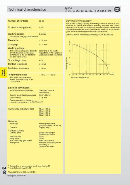
Current carry<strong>in</strong>g capacity<br />
The current carry<strong>in</strong>g capacity is limited by maximum temperature of<br />
materials for <strong>in</strong>serts and contacts <strong>in</strong>clud<strong>in</strong>g term<strong>in</strong>als. The current<br />
capacity curve is valid for cont<strong>in</strong>uous, non <strong>in</strong>terrupted current loaded<br />
contacts of connectors when simultaneous power on all contacts is<br />
given, <strong>with</strong>out exceed<strong>in</strong>g the maximum temperature.<br />
Control and test procedures accord<strong>in</strong>g to DIN IEC 60 512<br />
Work<strong>in</strong>g current<br />
Ambient temperature<br />
Electrical term<strong>in</strong>ation<br />
Male and female connectors<br />
Diameter of pcb plated through holes<br />
pcb thickness<br />
Recommended pcb holes for<br />
<strong>press</strong>-<strong>in</strong> process <strong>in</strong> acc. to EN 60 352-5 2)<br />
Compliant <strong>press</strong>-<strong>in</strong><br />
term<strong>in</strong>ations<br />
0.94-1.09 mm<br />
≥ 1.6 mm<br />
Insertion and <strong>with</strong>drawal force<br />
32pol. ≤ 30 N<br />
48pol. ≤ 45 N<br />
64pol. ≤ 60 N<br />
96pol. ≤ 90 N<br />
Materials<br />
Mould<strong>in</strong>gs<br />
Contacts<br />
Contact surface<br />
Contact zone<br />
Press-<strong>in</strong> zone<br />
Wrap zone<br />
<strong>with</strong> selectively gold plated<br />
wrap posts<br />
Thermoplastic res<strong>in</strong>,<br />
glass-fibre filled, UL 94-V0<br />
Copper alloy<br />
plated accord<strong>in</strong>g to<br />
performance level 1)<br />
t<strong>in</strong>ned<br />
t<strong>in</strong>ned<br />
wrap zone: t<strong>in</strong>ned<br />
<strong>in</strong>terface zone: gold plated<br />
accord<strong>in</strong>g to<br />
performance level 3<br />
<strong>04</strong> .<br />
10<br />
1)<br />
Explanation of performance levels see <strong>chapter</strong> 00<br />
2)<br />
for details see page <strong><strong>04</strong>.</strong><strong>04</strong><br />
Mat<strong>in</strong>g conditions see <strong>chapter</strong> 00<br />
Tool<strong>in</strong>g see <strong>chapter</strong> 30