Gigaset N720 DECT IP Multicell System
Gigaset N720 DECT IP Multicell System
Gigaset N720 DECT IP Multicell System

You also want an ePaper? Increase the reach of your titles
YUMPU automatically turns print PDFs into web optimized ePapers that Google loves.
<strong>N720</strong> <strong>DECT</strong> <strong>IP</strong><strong>Multicell</strong> <strong>System</strong>Site Planning and Measurement GuideVo<strong>IP</strong>on www.voipon.co.uk sales@voipon.co.uk Tel: +44 (0)1245 808195 Fax: +44 (0)1245 808299
Vo<strong>IP</strong>on www.voipon.co.uk sales@voipon.co.uk Tel: +44 (0)1245 808195 Fax: +44 (0)1245 808299
Table of ContentsTable of ContentsSafety precautions . . . . . . . . . . . . . . . . . . . . . . . . . . . . . . . . . . . . . . . . . . . . . . . . . 2Introduction . . . . . . . . . . . . . . . . . . . . . . . . . . . . . . . . . . . . . . . . . . . . . . . . . . . . . . . 3The <strong>Gigaset</strong> <strong>N720</strong> <strong>DECT</strong> <strong>IP</strong> <strong>Multicell</strong> <strong>System</strong> . . . . . . . . . . . . . . . . . . . . . . . . . . . . . . . . . . . . 3Criteria for an optimum <strong>DECT</strong> wireless network . . . . . . . . . . . . . . . . . . . . . . . . . . . . . . . . 5How to proceed . . . . . . . . . . . . . . . . . . . . . . . . . . . . . . . . . . . . . . . . . . . . . . . . . . . . . . . . . . . . . . 8Projecting the <strong>DECT</strong> network . . . . . . . . . . . . . . . . . . . . . . . . . . . . . . . . . . . . . . . 9Determining the requirements for the telephone network . . . . . . . . . . . . . . . . . . . . . 9Conditions for the positioning of the base stations . . . . . . . . . . . . . . . . . . . . . . . . . . . . 10Preliminary identification of the positions of the base stations . . . . . . . . . . . . . . . . . 18Taking measurements . . . . . . . . . . . . . . . . . . . . . . . . . . . . . . . . . . . . . . . . . . . 20Defining limit values . . . . . . . . . . . . . . . . . . . . . . . . . . . . . . . . . . . . . . . . . . . . . . . . . . . . . . . . . 21Measuring the wireless range of the planned base stations . . . . . . . . . . . . . . . . . . . . 24Evaluating measurements . . . . . . . . . . . . . . . . . . . . . . . . . . . . . . . . . . . . . . . . . . . . . . . . . . . . 28Working with the <strong>Gigaset</strong> <strong>N720</strong> SPK PRO . . . . . . . . . . . . . . . . . . . . . . . . . . 29Checking the package contents . . . . . . . . . . . . . . . . . . . . . . . . . . . . . . . . . . . . . . . . . . . . . . 29Further recommended accessories . . . . . . . . . . . . . . . . . . . . . . . . . . . . . . . . . . . . . . . . . . . 30Before you begin . . . . . . . . . . . . . . . . . . . . . . . . . . . . . . . . . . . . . . . . . . . . . . . . . . . . . . . . . . . . 31Setting up the measuring base station . . . . . . . . . . . . . . . . . . . . . . . . . . . . . . . . . . . . . . . . 31Starting up the measuring handset . . . . . . . . . . . . . . . . . . . . . . . . . . . . . . . . . . . . . . . . . . . 35Operating the measuring handset . . . . . . . . . . . . . . . . . . . . . . . . . . . . . . . . . . . . . . . . . . . . 37<strong>DECT</strong> installations in special environments . . . . . . . . . . . . . . . . . . . . . . . . 41Customer care and help . . . . . . . . . . . . . . . . . . . . . . . . . . . . . . . . . . . . . . . . . . 43Questions and answers . . . . . . . . . . . . . . . . . . . . . . . . . . . . . . . . . . . . . . . . . . . . . . . . . . . . . . 43Environment . . . . . . . . . . . . . . . . . . . . . . . . . . . . . . . . . . . . . . . . . . . . . . . . . . . . 43Our environmental mission statement . . . . . . . . . . . . . . . . . . . . . . . . . . . . . . . . . . . . . . . . 43Environmental management system . . . . . . . . . . . . . . . . . . . . . . . . . . . . . . . . . . . . . . . . . 43Disposal . . . . . . . . . . . . . . . . . . . . . . . . . . . . . . . . . . . . . . . . . . . . . . . . . . . . . . . . . . . . . . . . . . . . . 43Appendix . . . . . . . . . . . . . . . . . . . . . . . . . . . . . . . . . . . . . . . . . . . . . . . . . . . . . . . 44Care . . . . . . . . . . . . . . . . . . . . . . . . . . . . . . . . . . . . . . . . . . . . . . . . . . . . . . . . . . . . . . . . . . . . . . . . . 44Contact with liquid . . . . . . . . . . . . . . . . . . . . . . . . . . . . . . . . . . . . . . . . . . . . . . . . . . . . . . . . . . 44Authorisation . . . . . . . . . . . . . . . . . . . . . . . . . . . . . . . . . . . . . . . . . . . . . . . . . . . . . . . . . . . . . . . . 44Specifications . . . . . . . . . . . . . . . . . . . . . . . . . . . . . . . . . . . . . . . . . . . . . . . . . . . . . . . . . . . . . . . . 45Accessories . . . . . . . . . . . . . . . . . . . . . . . . . . . . . . . . . . . . . . . . . . . . . . . . . . . . . . 46Glossary . . . . . . . . . . . . . . . . . . . . . . . . . . . . . . . . . . . . . . . . . . . . . . . . . . . . . . . . 47Index . . . . . . . . . . . . . . . . . . . . . . . . . . . . . . . . . . . . . . . . . . . . . . . . . . . . . . . . . . . 511Vo<strong>IP</strong>on www.voipon.co.uk sales@voipon.co.uk Tel: +44 (0)1245 808195 Fax: +44 (0)1245 808299
Safety precautionsSafety precautionsWarningRead the safety precautions and the user guide before use.Use only the power adapter supplied.Use only the recommended, rechargeable batteries (£ page 45) as this couldotherwise result in significant health risks and personal injury.Using your telephone may affect nearby medical equipment. Be aware of thetechnical conditions in your specific location e.g., doctor's surgery.Do not hold the rear of the handset to your ear when it is ringing or whenspeaker mode is activated, otherwise you risk serious and permanent damageto your hearing.Your <strong>Gigaset</strong> is compatible with the majority of digital hearing aids on the market.However, perfect function with all hearing aids cannot be guaranteed.The handset may cause an unpleasant humming or whistling noise in hearingaids or cause them to overload. If you require assistance, please contact thehearing aid supplier.Do not install the base station and charger in bathrooms or shower rooms.The base station is not splashproof.Do not use the devices in environments with a potential explosion hazard, forexample, paint shops.If you give your phone to a third party, make sure you also give them theuser guide.Remove faulty devices from use or have them repaired by our Service team, asthese could interfere with other wireless services.2Vo<strong>IP</strong>on www.voipon.co.uk sales@voipon.co.uk Tel: +44 (0)1245 808195 Fax: +44 (0)1245 808299
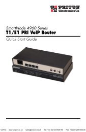
IntroductionIntroductionThis document explains the preparations necessary to install a multi-cell <strong>DECT</strong> networkand take measurements for the optimum positioning of the base stations. It also providestechnical and practical background information.The <strong>Gigaset</strong> <strong>N720</strong> <strong>DECT</strong> <strong>IP</strong> <strong>Multicell</strong> <strong>System</strong>The <strong>Gigaset</strong> <strong>N720</strong> <strong>DECT</strong> <strong>IP</strong> <strong>Multicell</strong> <strong>System</strong> is a <strong>DECT</strong> multi-cell system for connecting<strong>DECT</strong> base stations to a Vo<strong>IP</strong> PABX. It combines the options of <strong>IP</strong> telephony with the useof <strong>DECT</strong> telephones.The following illustration shows the components of the <strong>Gigaset</strong> <strong>N720</strong> <strong>DECT</strong> <strong>IP</strong> <strong>Multicell</strong><strong>System</strong> and how they are embedded in the <strong>IP</strong> telephone environment:<strong>DECT</strong> Manager<strong>Gigaset</strong> <strong>N720</strong> DM PRO<strong>Gigaset</strong> <strong>IP</strong> PRO telephonese.g., <strong>Gigaset</strong> DE900 <strong>IP</strong> PROPABXVo<strong>IP</strong>, ISDN, analogue<strong>DECT</strong>base stations<strong>Gigaset</strong> <strong>N720</strong><strong>IP</strong> PROLANHandover & roamingConfiguration viaWeb interface<strong>Gigaset</strong>handsetsu <strong>DECT</strong> Manager <strong>Gigaset</strong> <strong>N720</strong> DM PROCentral management station for managing the <strong>DECT</strong> network. One <strong>DECT</strong> Managermust be used for each installation.– Manages up to 20 <strong>DECT</strong> base stations– Manages up to 100 handsets on multi-cell systems– Enables division into subnets (Cluster formation)– Forms the interface to an <strong>IP</strong> PABX (e.g., <strong>Gigaset</strong> T500 PRO or <strong>Gigaset</strong> T300 PRO)A Web user interface is available for configuring and administering the <strong>DECT</strong> network.u <strong>Gigaset</strong> <strong>N720</strong> <strong>IP</strong> PRO <strong>DECT</strong> base stations– These are the cells of the <strong>DECT</strong> telephone network.– Each base station can manage up to eight calls simultaneously (see the Capacitysection £ page 6)3Vo<strong>IP</strong>on www.voipon.co.uk sales@voipon.co.uk Tel: +44 (0)1245 808195 Fax: +44 (0)1245 808299
Introductionu <strong>Gigaset</strong> handsets– Up to 100 handsets can be connected and up to 30 calls conducted simultaneously.The following handsets are recommended: <strong>Gigaset</strong> SL610H, SL400H, S810H, E49H.– Subscribers can accept or initiate calls in all <strong>DECT</strong> cells with their handset (Roaming),and can also switch between the <strong>DECT</strong> cells during a call (Handover).u PABXYou can connect your <strong>DECT</strong> telephone system to a PABX for Vo<strong>IP</strong>, ISDN or analoguetelephony, e.g., a <strong>Gigaset</strong> T500 PRO.– Establishes the connection to a public telephone network for analogue, Vo<strong>IP</strong> orISDN calls.– Enables central management of telephone connections, directories, network mailboxes,etc.u Cluster formation with <strong>Gigaset</strong> <strong>N720</strong> <strong>DECT</strong> <strong>IP</strong> <strong>Multicell</strong> <strong>System</strong>You can divide <strong>DECT</strong> base stations that you have installed at your location into severalindependent groups, i.e., clusters, and manage them using one <strong>Gigaset</strong> <strong>N720</strong> DM PRO<strong>DECT</strong> Manager.Cluster 1 <strong>DECT</strong>Cluster 2ManagerLANThe <strong>DECT</strong> Manager is connected to the base stations and the PABX via the local networkand is therefore not dependent on <strong>DECT</strong> ranges. This means that you can installseparate <strong>DECT</strong> islands at your location but manage them centrally, i.e., they haveaccess to the centrally configured <strong>IP</strong> connections, directories, etc.For further information about the options provided by the <strong>Gigaset</strong> <strong>N720</strong> <strong>DECT</strong> <strong>IP</strong> <strong>Multicell</strong><strong>System</strong>, and about installing, configuring and operating the <strong>Gigaset</strong> devices mentioned,see the relevant user guide. These are provided on the product CD or on the Internet atwww.gigaset.com/pro.<strong>Gigaset</strong> offers the <strong>Gigaset</strong> <strong>N720</strong> SPK PRO (Site Planning Kit) to help you with measuringthe wireless coverage and quality of your <strong>DECT</strong> network. For information on setting upand using the <strong>Gigaset</strong> measuring equipment, see the Working with the <strong>Gigaset</strong> <strong>N720</strong>SPK PRO chapter £ page 29.4Vo<strong>IP</strong>on www.voipon.co.uk sales@voipon.co.uk Tel: +44 (0)1245 808195 Fax: +44 (0)1245 808299
Criteria for an optimum <strong>DECT</strong> wireless networkIntroductionA carefully planned <strong>DECT</strong> wireless network with adequate coverage is the prerequisite foroperating a telephone system that offers good call quality and sufficient call options forall subscribers in all buildings and areas belonging to the PABX.It is difficult to assess the technical wireless conditions of a <strong>DECT</strong> installation in advanceas they are influenced by many environmental factors. Therefore, the specific circumstanceson-site must be determined by taking measurements. This produces a reliablestatement about the material required as well as the locations of the wireless units.Various aspects need to be taken into consideration when planning a <strong>DECT</strong> wireless network.The following requirements must be considered when deciding how many basestations are required and where they should be placed:u Sufficient <strong>DECT</strong> wireless coverage of the entire site so that every subscriber can bereached.u Sufficient wireless channels (<strong>DECT</strong> bandwidth), in particular in "hotspots", to avoidcapacity bottlenecks.u Sufficient overlap of cells to enable synchronisation of the base stations and to guaranteefreedom of movement for subscribers when making calls.Wireless coverageThe selection of locations where the base stations are to be installed should guaranteeoptimum wireless coverage and enable cost-effective wiring.Optimum wireless coverage is achieved if the required reception quality is delivered at allpoints of the wireless network. If costs need to be considered, this should be done with aminimum number of <strong>DECT</strong> base stations.To ensure an interference-free switch of call connections from one cell to another (handover),there must be an area where good reception is ensured for both base stations. Toachieve this, a minimum quality for reception must be defined.Wireless cellBase stationOverlap5Vo<strong>IP</strong>on www.voipon.co.uk sales@voipon.co.uk Tel: +44 (0)1245 808195 Fax: +44 (0)1245 808299
IntroductionSignal transmissionThe ideal signal transmission of a base station isshaped like a ring, i.e., so that the registeredhandsets can be the same distance away fromthe base station in all directions without thewireless signal being interrupted.However, the transmission is influenced by variousenvironmental conditions. For example,obstacles such as walls or metal doors canimpede the wireless signals or interfere withtheir even transmission.You should investigate the actual conditionsthat the planned wireless network will be subjectedto by measuring the signal transmissionof the measuring base station at appropriatepositions.CapacityThe capacity of the cells must be large enough to guarantee that the subscribers can bereached in high-density traffic. A cell is at full capacity when the number of connectionsrequired for each base station is larger than the number of possible connections.A <strong>Gigaset</strong> <strong>N720</strong> <strong>IP</strong> PRO can manage eight connections simultaneously when operated innarrowband mode (£Narrowband mode, page 49). In broadband mode, four simultaneousconnections are possible (£Broadband mode, page 47).There are two options for increasing the capacity:u Reducing the distance between the base stations.This means that the cells overlap more, givingthe subscriber access to the base stations ofthe neighbouring cells. This results in a moreeven wireless quality. However, this can resultin considerable installation costs for an existingsystem.u Installing parallel base stations.The cell size remains generally constant butthe number of possible connections increases.Installing the base stations close to oneanother means that the additional assemblycosts are low, but a minimum distance must beobserved between the base stations (£Technicalconditions, page 11).To keep the costs for the devices and for theinstallation and maintenance low, as few base stations as possible should be installed.6Vo<strong>IP</strong>on www.voipon.co.uk sales@voipon.co.uk Tel: +44 (0)1245 808195 Fax: +44 (0)1245 808299
IntroductionOverlapping and synchronisingFor interference-free cooperation in a multi-cell <strong>DECT</strong> network, the base stations mustsynchronise. In order to synchronise the base stations and ensure a smooth handover, thecells must overlap.Synchronisation overlapHandover overlapA sufficient number of large overlapping zones between neighbouring cells must beensured. To achieve synchronisation, the reception must be of sufficient quality to ensurethat the base stations can receive one another securely. For a handover, a handset musthave a connection of sufficient quality to both base stations. You will find informationabout possible interferences in the Defining limit values section £ page 21.The more densely the base stations are installed, the greater the overlap. Here, a compromisemust be found between keeping the area relatively open and installing the lowestpossible number of base stations.7Vo<strong>IP</strong>on www.voipon.co.uk sales@voipon.co.uk Tel: +44 (0)1245 808195 Fax: +44 (0)1245 808299
IntroductionHow to proceedUse the following guide to quickly locate the most important topics.Information on ...... is located here.Determining the requirements for the telephone networkDetermine the requirements for the telephone network and collectinformation about the environmental conditions for the planned<strong>DECT</strong> wireless network.gpage 9Creating an installation planCreate a building plan and enter the planned <strong>DECT</strong> base stations inthis plan. You should take account of the general conditions determinedand the technical requirements of <strong>DECT</strong> telephony in theprocess.gpage 18Taking measurementsUse the installation plan to take measurements and adapt the installationplan to your measurement results.gpage 20Working with the <strong>Gigaset</strong> measuring equipmentHave you purchased the <strong>Gigaset</strong> <strong>N720</strong> SPK PRO (Site Planning Kit)?Here you can read about how to set up the measuring equipmentand how to use it to take measurements.gpage 29Special environmentsDo you want to set up your <strong>DECT</strong> network in a difficult environment?Helpful information and tips are available here.gpage 41If you have any questions about using your measuring devices, please contactour Customer care team (£ page 43).8Vo<strong>IP</strong>on www.voipon.co.uk sales@voipon.co.uk Tel: +44 (0)1245 808195 Fax: +44 (0)1245 808299
Projecting the <strong>DECT</strong> networkProjecting the <strong>DECT</strong> networkThere are a number of conditions to be considered when setting up a <strong>DECT</strong> network. Theyaffect the subscribers' requirements for the telephone system as well as the technicalrequirements for the <strong>DECT</strong> wireless network. These conditions must therefore berecorded and evaluated in a projection phase.To project your <strong>DECT</strong> network, proceed as follows:u First determine the requirements for the telephone network and establish the environmentalconditions for the <strong>DECT</strong> wireless network.u Define how many base stations are required and their probable optimum positioning.Create an installation plan for the base stations.u Take measurements to check whether the positioning of the base stations at theassumed positions meets the requirements and whether the reception and soundquality is sufficient everywhere. If necessary, change the installation plan to optimisethe <strong>DECT</strong> wireless network.Determining the requirements for the telephone networkClarify the following questions to determine the requirements for the telephone network:Subscribers and subscriber behaviouru How many employees should be able to make calls and how many subscribers shouldbe able to make calls simultaneously?– How many handsets are required?– How many base stations are required?u Where should telephone calls be possible?– In which buildings (floors, stairwell, basement, underground garage)?– Outdoors (on footpaths, on the car park)?For more information about this, please refer to the information in the section Outsidearea, £ page 42.– How are the handsets distributed from a location perspective?u How many calls will be made?– What is the telephony behaviour of the subscribers? How long is the average call?– Where are the hotspots, i.e., where do a lot of subscribers gather simultaneously(open-plan office, canteen, cafeteria, etc.)?– Where are telephone conferences held? How many telephone conferences are heldand how long are these?Environmental conditionsu Where is the site that is to be covered by the <strong>DECT</strong> wireless network?– Total area of the required wireless coverage– Position and dimensions of the rooms, building plan– Number of floors, basements¤ Request a building plan that shows positions and dimensions and that can be usedto document the subsequent installation planning.9Vo<strong>IP</strong>on www.voipon.co.uk sales@voipon.co.uk Tel: +44 (0)1245 808195 Fax: +44 (0)1245 808299
Projecting the <strong>DECT</strong> networku What is the basic structure of the building?– What materials and construction types have been used for the buildings?– What type of windows does the building have (e.g., tinted glass)?– What construction changes are expected in the near future?u What disruptive influences can be identified?– What are the walls made of (concrete, brick, etc.)?– Where are the lifts, fire doors, etc. located?– What furniture and devices are present or planned?– Are there other wireless sources in the vicinity?For detailed information on material characteristics and interference factors, £ page 16.Conditions for the positioning of the base stationsFeatures of the <strong>Gigaset</strong> <strong>N720</strong> <strong>DECT</strong> <strong>IP</strong> <strong>Multicell</strong> <strong>System</strong>u A <strong>Gigaset</strong> <strong>N720</strong> DM PRO <strong>DECT</strong> Manager can manage a maximum of 20 base stationsand 100 handsets.u The <strong>DECT</strong> network can be divided into clusters; i.e., you can install several independent<strong>DECT</strong> islands that are managed centrally by a <strong>DECT</strong> Manager.u A <strong>Gigaset</strong> <strong>N720</strong> <strong>IP</strong> PRO base station can establish a maximum of eight connectionssimultaneously (four connections in Broadband mode).This must be taken into consideration in the capacity calculations (£ page 13).Technical conditionsThe following values can be used as a guide for the planning. They are values that areinfluenced by environmental conditions and that should therefore be checked via measurements.u The wireless range of a <strong>DECT</strong> base station for handsets is (guide values)– Up to 50 m indoors– Up to 300 m outdoorsThese guide values do not apply to the maximum possible distance between two basestations. To ensure the handover of a handset from the cell of one base station to thecell of another, this distance is derived from the necessary overlap zone.u Ensure adequately sixed overlap zones between neighbouring cells are taken intoconsideration. For an interference-free handover, a spatial overlap of 5 to 10 metreswith satisfactory signal strength should be sufficient, even for fast walking. Neighbouringbase stations must be able to receive one another with sufficient signal strength toguarantee the synchronisation and handover (£ page 21).10Vo<strong>IP</strong>on www.voipon.co.uk sales@voipon.co.uk Tel: +44 (0)1245 808195 Fax: +44 (0)1245 808299
Projecting the <strong>DECT</strong> networku Maintain sufficient distance between the base stations as they can interfere with oneanother. The minimum distance depends on the circumstances. If no obstacles arepresent, the required distance can be 5 to 10 metres. If there is an absorbent wall orabsorbent furniture between the base stations, 1 to 2 metres may be sufficient. Youwill also find information about possible interferences in the Material characteristicsand interference factors section £ page 16.u In a horizontal direction, good connections can still be established behind 2–3 normalbrick walls. In a vertical direction and on the ground floor or in basements, concreteceilings are difficult to penetrate. This means that every floor may have to be suppliedseparately.u Please note that in empty buildings, adding furniture and equipment (machines, movablewalls, etc.) at a later stage will affect the wireless quality.u Openings in obstacles improve the technical wireless conditions.u Consider any possible interference factors (£ page 16).Installation guidelinesThe following points must be considered when installing <strong>DECT</strong> base stations:u For wireless coverage within a building, always install the base stations on internalwalls. Information on installation in an outside area, £ page 42.u Depending on the room height, the optimum installation height of a base station isbetween 1.8 and 3 m. If you want to install the base stations at a lower height, interferencecan occur as a result of furniture or movable objects. There should be a minimumclearance of 0.5 m to the ceiling.u We recommend installing all base stations at the same height.u The <strong>Gigaset</strong> <strong>N720</strong> <strong>IP</strong> PRO base stations require an Ethernet connection to the PABX, i.e.,it must be possible to connect to the LAN.u The <strong>Gigaset</strong> <strong>N720</strong> <strong>IP</strong> PRO base stations are powered by PoE (Power over Ethernet,IEEE 802.3af ). Therefore, you do not normally require a power connection. However, ifyou use an Ethernet switch that does not support PoE, you can use a PoE injector as analternative. If there is an option of connecting to the mains power supply in the vicinityof the base station, you can also use the power adapter to provide a power supply (tobe ordered separately).u Do not install the base station in suspended ceilings, cupboards or other closed furnishings.The wireless coverage can be significantly reduced, depending on the materialsused.u The base station should be installed vertically.u The location and alignment of the base station installed should be identical to theposition deemed optimum during the measurement stage.u Avoid installation in the direct vicinity of cable channels, metal cupboards or otherlarger metal parts. These can reduce the radiation and couple into interfering signals.There should be a minimum distance of 50 cm.u Observe the safety distances and safety regulations. Observe the regulations specifiedin rooms where there is a danger of explosions.11Vo<strong>IP</strong>on www.voipon.co.uk sales@voipon.co.uk Tel: +44 (0)1245 808195 Fax: +44 (0)1245 808299
Projecting the <strong>DECT</strong> networkThe capacity must always be adjusted to the highest possible traffic volume ifcapacity bottlenecks are to be excluded.Traffic volumeThe traffic volume is expressed in "erlangs (E)". One erlang corresponds to the continuousfull capacity utilisation of one connection channel in a specific period. Erlangs are usuallycalculated over an observation period of one hour. Accordingly, the occupation of a connectionchannel over one hour equals one erlang.For example: if all eight connections of a base station are continuously occupied, this correspondsto eight E. If a connection is occupied for 20 minutes, this corresponds to 1/3 E.Examples:Let us assume that 500 calls lasting 3 minutes each are made within one hour.500 x 3 min/60 min = 25 ETherefore, at least 25 connection channels, i.e., four base stations (in Narrowband mode),would be necessary for this call volume.However, this only applies if the grade of service is less than 4%. With a grade of serviceof 4%, you need only three base stations, i.e., 24 connection channels. With a grade ofservice of 4%, it is permissible for 20 calls from 500 not to be established. This means thatonly 480 connections have to be achieved. The calculation is as follows:480 x 3 min/60 min = 24 ESince the traffic volume is not normally evenly distributed over the site to be covered, thetraffic volume must be calculated for each area (offices, reception, hotspots, stairwell, etc.)in order to determine the relevant number of base stations that need to be installed.Grade ofserviceCalls at 3 min. per hour10 50 100 5000 % 0.5 E 2.5 E 5 E 25 E2 % 0.49 E 2.45 E 4.9 E 24.5 E4 % 0.48 E 2.4 E 4.8 E 24 EGrade ofserviceCalls at 15 min. per hour10 50 100 5000% 2.5 E 12.5 E 25 E 125 E2% 2.45 E 12.25 E 24.5 E 122.5 E4% 2.4 E 12 E 24 E 120 EThe table contains somesample values for the calculationof the traffic volumedepending on the grade ofservice, call duration andnumber of calls per hour.Using the data you havedetermined about thetelephony behaviour, youcan realistically estimateyour requirements.14Vo<strong>IP</strong>on www.voipon.co.uk sales@voipon.co.uk Tel: +44 (0)1245 808195 Fax: +44 (0)1245 808299
Alternative calculation for small systemsProjecting the <strong>DECT</strong> networkFor smaller systems, an approximate evaluation of the traffic volume can be sufficient.Examples:The traffic volume is evaluated for every area as "low", "medium" or "high". The evaluationspecifies the number of handsets that can conduct calls simultaneously as a percentage:Evaluation % Maximum number of handsets that can beoperated from one base stationLow Approx. 10% 80Medium Approx. 25% 32High Approx. 50% 16HotspotsA hotspot is an area in which more calls than average are conducted simultaneously, e.g.,open-plan offices or other areas where there are a lot of handsets in a small space.You can cover such areas with several base stations since the <strong>DECT</strong> bandwidths in the coverageareas of neighbouring base stations add up. The <strong>DECT</strong> standard provides 120 radiochannels that can be shared by several base stations. In practice, however, approximatelyonly one quarter of these radio channels can be used without special measures, since theneighbouring channels interfere with one another. This results in a practical value of amaximum of 30 simultaneous connections. With a maximum of eight handsets per basestation, this means that four <strong>Gigaset</strong> <strong>N720</strong> <strong>IP</strong> PRO base stations would be required.If we assume that a maximum of 50% of the available handsets are making a call simultaneouslyin a hotspot, 60 handsets can be used with four base stations.If interference frequently occurs at a hotspot or more than 30 connections are requiredsimultaneously, the following measures are possible:u Distribute the base stations that cover the hotspot as widely as possible at the boundariesof the hotspot so that they are as far away from each other as possible and mutualinterference is minimised.u If this measure is not sufficient, use walls or other suitable means to diminish thestrong signals.u It might also be helpful, if the circumstances at the location allow, to arrange the basestations in the shape of a ball, i.e., cover the hotspot through floors and ceilings.When optimising the coverage of the hotspot areas, make sure that handsets do not suddenlyoccupy the call channels of the hotspot base stations that were previously suppliedby other base stations. When establishing a connection, handsets always occupy channelsof the base station that provides the strongest signal. Therefore, moving the hotspotbase stations may affect other base stations and you may have to relocate the base stationsof the entire network.15Vo<strong>IP</strong>on www.voipon.co.uk sales@voipon.co.uk Tel: +44 (0)1245 808195 Fax: +44 (0)1245 808299
Projecting the <strong>DECT</strong> networkMaterial characteristics and interference factorsThere are a number of interference factors that influence the range and quality of thetransmission in particular. The types of interference factors include:u Interference as a result of obstacles that diminish the signal transmission, creatingradio shadowsu Interference through reflection that restricts the call quality (e.g., crackling or backgroundnoise)u Interference through other radio signals that can lead to errors in transmissionInterference through obstaclesPossible obstacles are:u Building constructions and installations such as reinforced concrete ceilings and walls,stairwells, long corridors with fire doors, uptakes and cable channels.u Metal-clad rooms and objects such as cold stores, computer rooms, metallised glassareas (reflections), firewalls, tank systems, refrigerators, electrical boilers etc.u Movable metal objects such as lifts, cranes, carts, escalators, shuttersu Room furnishings such as metal shelves, filing cabinetsu Electronic devices.It is often difficult to locate the exact source of the interference; particularly if the receptionpower of the local <strong>DECT</strong> signals fluctuates strongly within a few centimetres. In thesecases, the interference can be reduced or corrected by small changes to the position.Please noteWireless coverage in lifts is normally poor or not available at all (£ page 41).Loss of range through building materials in comparison to a free wirelessfield:Glass, wood, untreated Approx. 10%Wood, treated Approx. 25%Plasterboard Approx. 27 – 41%Brick wall, 10 to 12 cm Approx. 44%Brick wall, 24 cm Approx. 60%Aerated concrete wall Approx. 78%Wired glass wall Approx. 84%Reinforced concrete ceiling Approx. 75 – 87%Metal-coated glass Approx. 100%16Vo<strong>IP</strong>on www.voipon.co.uk sales@voipon.co.uk Tel: +44 (0)1245 808195 Fax: +44 (0)1245 808299
Interference from other cells and networksProjecting the <strong>DECT</strong> network<strong>DECT</strong> is very robust against interference from other wireless networks. For example, coexistencewith WLAN is not a problem. Most other asynchronous <strong>DECT</strong> single base stationsdo not present a problem either.Problems may occur in special cases, such as an environment where there is a very highlevel of <strong>DECT</strong> usage. This applies when there are co-existing asynchronous <strong>DECT</strong> base stationsbut, even more so, when base stations have been installed too close together tocover a hotspot, for example.Despite sufficient signal strength, the following interference can occur:u Unexpected termination of the connectionu Loss of synchronisation of handsetsu Poor voice quality¤ When interference occurs because base stations are installed too closely together, tryto resolve the problem with the measures described in the Hotspots section (increasethe distances, use obstacles to absorb the interference, £ page 15)¤ If you have found other <strong>DECT</strong> sources, check whether you can switch them off, relocatethem or integrate them in your <strong>DECT</strong> network.SummaryWireless traffic interference can have many causes that cannot all be determined inadvance, that increase or decrease due to mutual influences and that can change duringoperation.Therefore, the actual influence of interference factors on reception and voice quality canonly be determined by taking measurements. However, the measurements also only providean image of the wireless network at the time of measurement. We therefore recommendthat when you plan the <strong>DECT</strong> network areas where interference can be expected,you err on the side of caution when you interpret the limit values.17Vo<strong>IP</strong>on www.voipon.co.uk sales@voipon.co.uk Tel: +44 (0)1245 808195 Fax: +44 (0)1245 808299
Projecting the <strong>DECT</strong> networkPreliminary identification of the positions of the base stationsNow plan the positions of the base stations. Take the following into consideration:u The information you have collected regarding the requirements for the telephone networku Your synchronisation planningu The technical conditions for the wireless <strong>DECT</strong>.First create a plan in which you then enter the locations of the base stations. You can useexisting building and supply plans, if applicable. For very large buildings, you may be ableto work with partial floor plans and then merge the results of the measurements into theevaluation.Creating a planning drawingCreate a planning drawing from the information you have collected in the preliminaryexamination of the location. Enter building dimensions, hotspot areas and any sources ofinterference already identified.Examples:50 mHS30 mComputersWC/storeStairsHSu The numbers in the rooms reflect the required number of <strong>DECT</strong> telephones.u Areas with high-density traffic are marked as hotspots (HS).u The walls marked in bold are assumed to have a high absorption effect, or reflectionscan be expected.u The dotted lines on the two outer walls indicate tinted windows (coated with metalfilm).u The stairwell should be covered by <strong>DECT</strong> wireless transmission. There is a lift here.18Vo<strong>IP</strong>on www.voipon.co.uk sales@voipon.co.uk Tel: +44 (0)1245 808195 Fax: +44 (0)1245 808299
Projecting the <strong>DECT</strong> networkPositioning the base stations in the planNow enter the base stations.HSComputersWC/storeStairsHSu The example shows five base stations.u One base station is used to show how, by drawing in transmission directions for thewireless signal, you can estimate how many base stations can see each other andwhich building areas the wireless signal could reach.u For the hotspot in the room at the top left, two additional base stations have beenplanned in parallel.u If full wireless coverage is required for the stairwell, measurements must be performedto check whether a further base station has to be located here.u You must also check whether the base stations planned are sufficient for the secondhotspot.You then check these initial assumptions later using the measurements (page 20).19Vo<strong>IP</strong>on www.voipon.co.uk sales@voipon.co.uk Tel: +44 (0)1245 808195 Fax: +44 (0)1245 808299
Taking measurementsTaking measurementsYou have:u Determined the requirements for the telephone network (£ page 9)u Planned the number of base stations and their positions (£ page 18)u Set up and operated the measurement equipment.If you are using the <strong>Gigaset</strong> <strong>N720</strong> SPK PRO (Site Planning Kit), you can find informationabout setting it up on £ page 29.You can now start the measurements for your planned <strong>DECT</strong> network. The aim of themeasurements is to determine the following:u Is sufficient wireless coverage and a good voice quality guaranteed everywhere in thedesired area?u Is synchronisation of the bases stations ensured in their planned positions?u Is a handover between the base stations possible where it is required?The requirements from these three aspects must be taken into account in the measurements.For information on this, please also refer to the Conditions for the positioning ofthe base stations section £ page 10.Notes for taking the measurementsu Take two different measurements:– Measure the connection quality in the wireless coverage area for the planned basestations.– Measure the signal strength between the base stations (synchronisation measurement).u To measure the connection quality, establish a telephone connection. It is helpful if themeasurements are performed by two people, since they can check the voice qualityand interference on both measuring handsets directly in a call. If only one person performsthe measurements, the connection quality can be checked using the test toneof the base station (£ page 38).u You can also test the connection quality by holding the handset to your ear as youmeasure, in the same way as you would in a real telephony situation. Turn around asyou do so. Note how the acoustics quality of the test tone changes. If interferenceoccurs at the limit of the range (e.g., crackling), power at the measuring site is critical.Your head can impair reception. For this reason, the test against your ear is an additionalcheck for verifying the reception quality in limit areas.u Use the measuring handset in idle status to measure the signal strength between thebase stations, as it is the measured signal strength and not the voice quality that is relevantin this situation.u Using the stand, position the measuring base station as precisely as possible in relationto the intended position for the base station.u To measure the signal strength between base stations, position the measuring handsetin the exact planned position of the base station. For example, if you want to positionthe base stations at a height of 3 m, make sure the measuring handset is at thisheight.u Move metal objects as far away as possible from the measuring base station as theycan influence the measurement.20Vo<strong>IP</strong>on www.voipon.co.uk sales@voipon.co.uk Tel: +44 (0)1245 808195 Fax: +44 (0)1245 808299
Taking measurementsu Document the progress of the measurement by entering it in the layout plan (horizontallyand, where applicable, vertically) and in a measurement log.u In order to be able to recognise subsequent changes, it is helpful to document theplanned assembly positions of the individual measurement series and their environmentwith photographs.u If the PABX is to be used for several floors or very high rooms (e.g., with a gallery), youmust also measure the vertical range and enter it in a plan of the building. For furtherinformation on this, please also refer to the <strong>DECT</strong> installations in special environmentschapter £ page 41.Fluctuations in the measurement resultWhen you are performing the measurements, the signal strength displayed on the handsetcan fluctuate strongly, particularly if you are moving around with the handset. Thebase stations have two aerials, so the handset displays the values for the aerial for whichit receives the best signal. Since the measuring handset takes measurements at definedtime intervals (2.5 seconds as standard), the values can change quickly.For example, if you block the signal for the aerial that is in a better position for the handsetwith part of your body, the handset receives the signal from the weaker aerial. Turningyour body slightly can significantly alter the measurement value, since the handset is suddenlyable to receive the signal from the "better" aerial. By moving around, you determinean average value that you can use as the measurement value.If the fluctuations are strong, it makes sense to perform the measurement while a connectionis established as you then have an additional check based on the voice quality.When the PABX is being operated in real-life situations, these fluctuations are barelynoticeable as the base stations automatically establish the connection with the best positionedaerial.Defining limit valuesDuring the measurement process, the measuring handsets receive wireless signals fromthe measuring base station and display various characteristics for the reception quality.The following are relevant for the reception quality:u Reception poweru Connection qualityThe values specified below are guidelines for determining limit values for operating the<strong>DECT</strong> telephone system under optimum conditions. Since the <strong>DECT</strong> network can berestricted by many factors that can also occur temporarily, we do not recommend positioningthe base stations at the limit values. Instead, you should include a buffer accordingto the requirements for grade of service and voice quality. It may be acceptable forexample, that voice quality is restricted at times in the basement, and that calls cannotalways be made there. In contrast, restrictions are unacceptable for meeting rooms wheretelephone conferences are held.21Vo<strong>IP</strong>on www.voipon.co.uk sales@voipon.co.uk Tel: +44 (0)1245 808195 Fax: +44 (0)1245 808299
Taking measurementsReception powerThe reception field strength is measured to assess the quality of transmission. The receptionpower (proportional to the field strength) is displayed on the measuring handset in dBm(£ page 48). A very good reception power is approximately –50 dBm. <strong>System</strong>s that aremeasured at up to –60 dBm generally offer a good quality. For measurements up to –70 dBm,the measurement must be checked and evaluated with an audio connection to ensure sufficientquality. A handover is no longer possible in this area.Different limit values can be used for the measurement, based on the quality or use ofspecific areas (e.g., office, corridor, basement). Different quality requirements can also bedefined at the various base stations within a partial system.Typical limit values for normal, low-interference environments are:§§1§§ Limit value for secured voice quality: –65 dBmThis is the value at which a handset must receive the signal of a base station for a subscriberto be able to benefit from good quality telephony. For an interference-freehandover, the handset must receive both base stations at this level of quality.§§2§§ Limit value for synchronisation: –70 dBmThis is the value at which a base station must receive the signal of another base stationto be able to synchronise.The following table gives an initial guideline for the quality of the wireless connection.Reception power–50 dBm Very good–60 dBm Good–65 dBm Satisfactory–70 dBm AdequateEvaluation of the quality–73 dBm Weak, not suitable–76 dBm Poor, not suitable22Vo<strong>IP</strong>on www.voipon.co.uk sales@voipon.co.uk Tel: +44 (0)1245 808195 Fax: +44 (0)1245 808299
Connection qualityTaking measurementsIn principle, the measurement of the field strength should always be supplemented by acheck of the connection quality. Interference, e.g., through reflection or external systemsthat influence the voice quality, can also occur with good reception power.Therefore, in addition to the reception power, the Frame quality is also displayed on themeasuring handset. This indicates the percentage rate of the packages received withouterrors in a measurement interval. The optimum value is 100%.As a rule of thumb, 2% reduction in the frame quality leads to a devaluation by one levelin the quality table illustrated above. Example: the measurement values –60 dBm with aframe quality of 94% lead to the evaluation "Poor, not suitable", since a quality loss of 6%leads to a devaluation by three levels.Reception power Frame quality Evaluation of the quality–60 dBm 100 % Good–60 dBm 98 % Satisfactory–60 dBm 96 % Adequate–60 dBm 94 % Weak, not suitable–60 dBm 92 % Poor, not suitable23Vo<strong>IP</strong>on www.voipon.co.uk sales@voipon.co.uk Tel: +44 (0)1245 808195 Fax: +44 (0)1245 808299
Taking measurementsMeasuring the wireless range of the planned base stationsTake two different measurements.§§1§§ Measure the connection quality between the measuring handset and measuring basestation in their wireless cells to ensure that sufficient voice quality is guaranteed at everyposition in the required coverage area. Taking the same measurement for the neighbouringstation produces the overlap zone required for a handover.§§2§§ Measure the strength of the signal from the measuring base station that you receive atthe planned position of the neighbouring base station to ensure sufficient synchronisationoverlap.Measurement sequenceThe sequence in which you measure the wireless range of the planned base stationsdepends on the size of your <strong>DECT</strong> network and your assumptions with regard to the existing"problem areas". As a rule of thumb, first measure the base stations whose positionshave the least leeway.Take the following aspects into consideration:u Assumed problem areasFor base stations that are to cover specific problem areas, e.g., a stairwell or entrancearea, there are often few alternative positioning options. In this case, measure thesebase stations first because the positioning of all other base stations depends on theseinitial positions.u For large installationsThe more base stations you use, the higher the requirements of the synchronisationhierarchy (£ page 12). In this case, we recommend starting with the base station forwhich a subsequent change would mean the greatest effort. This is usually the basestation with sync level 1. Start here and move outwards from sync level to sync level.u For small installationsHere it makes sense to start with the base station where the highest call traffic is to beexpected, e.g., base stations in hotspots or other high-traffic areas. Once the coverageof these areas is ensured by measurement, check the positioning of the other base stations.24Vo<strong>IP</strong>on www.voipon.co.uk sales@voipon.co.uk Tel: +44 (0)1245 808195 Fax: +44 (0)1245 808299
Taking measurementsMeasuring the cell of a base station¤ Temporarily secure the measuring base station in the position in which the base stationis to be installed.¤ Establish a telephone connection between the two measuring handsets or activatethe continuous test tone of the measuring base station (£ page 38).¤ Move away from the base station with the handset, observing the display and the signalin the earpiece, until the limit value of –65 dBm is displayed or a wireless transmissionboundary is reached (e.g., lift, exterior wall). Transfer this point to your plan andenter the value in the measurement log.¤ Use this method to determine the border line around the base station. The theoreticalideal case of a ring-shaped transmission is considerably altered in reality by walls(depending on the construction material) and metal furnishings.¤ Check the voice quality in the limit areas using the connection to the second measuringhandset or the measuring tone of the base station.¤ Enter deviations in the reception signal measurement of the voice quality in the layoutplan or the measurement log.2ADB1WC/storeCStairsComputersE9Example of a measurement log for the cell of a base stationMeasuring point Base station A1 –60 dBm/100%2 –65 dBm/98%. . . . . .. . . . . .9 –73 dBm/70%25Vo<strong>IP</strong>on www.voipon.co.uk sales@voipon.co.uk Tel: +44 (0)1245 808195 Fax: +44 (0)1245 808299
Taking measurementsIf you have measured the cells of several base stations, the results may look like this, forexample:MeasuringpointBase station A Base station B Base station C Base station D1 –60 dBm/100%2 –50 dBm/98%3 –65 dBm/100%4 –48 dBm/100%5 –55 dBm/98%6 –65 dBm/100% –50 dBm/100%7 –68 dBm/96% –59 dBm/100%8 –55 dBm/98% –46 dBm/98%9 –60 dBm/96%10 –52 dBm/98% –65 dBm/100%11 –63 dBm/100% –57 dBm/100%12 –48 dBm/98% –42 dBm/100%13 –46 dBm/98%14 –40 dBm/100%15 –60 dBm/98% –52 dBm/100%16 –43 dBm/100% –42 dBm/100%17 –56 dBm/100%18 –50 dBm/98%19 –53 dBm/100%20 –60 dBm/98%Measuring points where two base stations are received with at least –65 dBm are locatedin an overlap zone of the two base stations in which a handover is possible (highlightedgrey in the table).Measuring the synchronisation overlap of neighbouring basestationsFor the base stations to be able to synchronise, the signal strength between two neighbouringbase stations must not be less than –70 dBm. This value applies in good environmentalconditions, £ page 21.Proceed as follows for the measurements:¤ Leave the measuring base station at the last measuring site and proceed with thehandset to the planned position of a base station that is to synchronise with the firstbase station.In order to reliably assess the synchronisation, you must be located, with the handset,at the exact position of the planned base station (use a ladder to measure at the correctheight, if necessary).¤ Check whether the signal is within the limit of -70 dBm at 100% frame quality. If this isnot the case, you should change the location of the base station until this minimumrequirement is met.26Vo<strong>IP</strong>on www.voipon.co.uk sales@voipon.co.uk Tel: +44 (0)1245 808195 Fax: +44 (0)1245 808299
Taking measurements¤ Install the measuring base station at this location and take the measurements as forthe first position.¤ Enter the results in the plan and the measurement log.¤ Now take this measurement for all planned assembly locations.ADCBEExample of a measurement log for measuring the synchronisation overlapMeasuringpointBase station A Base station B Base station C Base station D Base station EA –52 dBm/100% –40 dBm/100% –58 dBm/100% ----B –50 dBm/100% –48 dBm/100% ---- –70 dBm/92%C –42 dBm/100% –46 dBm/100% –50 dBm/100% ----D –60 dBm/100% ----- –48 dBm/100% –64 dBm/100%E ---- –68 dBm/94% ---- –62 dBm/100%The result of the measurement is that the signal strength is sufficient for synchronisationeverywhere. Base station E only receives base station D with sufficient quality.Here, a sensible synchronisation hierarchy would be:Sync level 1Sync level 2Sync level 3Base station CBase stations A, B and DBase station E27Vo<strong>IP</strong>on www.voipon.co.uk sales@voipon.co.uk Tel: +44 (0)1245 808195 Fax: +44 (0)1245 808299
Taking measurementsEvaluating measurementsThe graphical display of your measurement results in the layout plan shows the overlapareas of the individually planned base stations.ADIn the example, limitation lines are drawn for the wireless coverage for base stations A andD. The overlap areas are very good for both stations; synchronisation is also guaranteedbetween A and D. However, the measurement results of the other stations must be usedto check whether a further base station is required in the shaded areas.¤ Using the measurement results (where necessary), define new positions for the basestations and check them with further measurements.Note that moving one installation location also influences the other measurementresults. Always consider how this affects the synchronisation of the base stations.¤ Enter the determined optimum installation locations for the base stations in the plan(including the height and special construction circumstances, if necessary). We recommendyou also document the assembly positions with photographs.¤ In particular, check rooms or areas with very high wireless signal shielding (e.g., lifts,reinforced concrete ceilings, etc.) and add further base stations to your plan wherenecessary.Once the measurements are complete and the positions of the base stations have beendefined, the telephone system can be installed. This is described in the user guide for the<strong>Gigaset</strong> <strong>N720</strong> <strong>IP</strong> PRO and <strong>Gigaset</strong> <strong>N720</strong> DM PRO.RecommendationAfter installation and commissioning of the <strong>DECT</strong> network, the voice quality, roamingand handover should be checked again with the system telephones.28Vo<strong>IP</strong>on www.voipon.co.uk sales@voipon.co.uk Tel: +44 (0)1245 808195 Fax: +44 (0)1245 808299
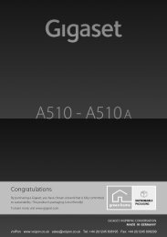
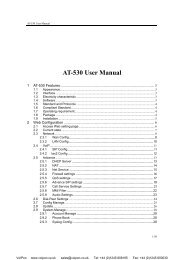
Working with the <strong>Gigaset</strong> <strong>N720</strong> SPK PROWorking with the <strong>Gigaset</strong> <strong>N720</strong> SPK PROThe <strong>Gigaset</strong> <strong>N720</strong> SPK PRO (Site Planning Kit) helps you to plan and install your <strong>DECT</strong>multi-cell system. It contains one measuring base station, two measuring handsets andfurther helpful accessories for exact determination of the <strong>DECT</strong> environmental conditionsfor the planned network and is delivered in a case.You can use the measuring devices in the case to determine the<strong>DECT</strong> wireless coverage at your location, establish how many basestations are required and their optimum location and find sourcesof interferences in the wireless network.Checking the package contents13452§§1§§ Measuring base station mounted on a carrier§§2§§ Battery pack with eight rechargeable batteries (AA)§§3§§ Battery charger with three different plug-in modules (Europe, Great Britain and the USA)§§4§§ Power adapter for measuring base station (only required if the device is not poweredvia batteries)§§5§§ Key for locking the case29Vo<strong>IP</strong>on www.voipon.co.uk sales@voipon.co.uk Tel: +44 (0)1245 808195 Fax: +44 (0)1245 808299
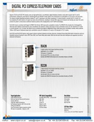
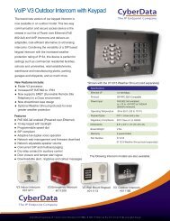
Working with the <strong>Gigaset</strong> <strong>N720</strong> SPK PRO6 7 8§§6§§ Two <strong>Gigaset</strong> S810H measuring handsets (specially calibrated for measurement operations)§§7§§ Eight rechargeable batteries (AAA) for the measuring handsets (two reserve batterieseach)§§8§§ Two chargers with power adapter for the measuring handsets9 10 11§§9§§ Two <strong>Gigaset</strong> ZX400 headsets§§10§§ CD-ROM with user documentation§§11§§ Planning and recording materials with penFurther recommended accessoriesStandTo obtain an exact measurement, we recommend that youmount the measuring base station and battery carrier securelyon a stand. The base carrier is fitted with a thread connectionfor this purpose. This enables you to simulate the installationof a base station at every possible height and check the layoutand range of the network.The stand should have a screw thread and be extendable to aheight of 2.50 to 3.00 m.30Vo<strong>IP</strong>on www.voipon.co.uk sales@voipon.co.uk Tel: +44 (0)1245 808195 Fax: +44 (0)1245 808299
Before you beginWorking with the <strong>Gigaset</strong> <strong>N720</strong> SPK PROPlease note that the measuring devices run on batteries that must be charged before youstart taking measurements. Bear this in mind when planning your time.You need eight batteries for the measuring base station, provided as a battery pack. Thecase contains a charging device for charging the battery pack. The charging time isapprox. three hours.You need two batteries for each measuring handset. These can be charged both in thechargers and in standard charging devices. The charging time in the charger is approx.8.5 hours.Please noteUse only the rechargeable batteries (£ page 45) recommended by <strong>Gigaset</strong> CommunicationsGmbH, i.e., never use conventional (non-rechargeable) batteries, otherwiseserious health risks and personal injury cannot be ruled out. For example, the outercasing of the batteries could be damaged or the batteries could explode. The phonecould also malfunction or be damaged as a result of using batteries that are not of therecommended type.Setting up the measuring base stationTo ensure freedom of movement when measuring and not be dependent on being ableto reach a power connection, operate the measuring base station with external batteries.The case contains a battery pack with eight integrated batteries and one charging devicefor this purpose.Preparing the base carrier¤ Remove the base carrier from the casetogether with the measuring base stationand battery pack.¤ Slide the lid to the left to open the batterycompartment §§1§§.Lift the lid gently with your fingernail toget past the lock on the right edge.1¤ Plug the connector on the battery packcable onto the two pins on the left side ofthe battery compartment §§2§§.Warning: the connector is shaped so that itcan only be attached the correct way round.If the connector is forced into the wrongposition, the pins may be damaged renderingthe device unusable.231Vo<strong>IP</strong>on www.voipon.co.uk sales@voipon.co.uk Tel: +44 (0)1245 808195 Fax: +44 (0)1245 808299
Working with the <strong>Gigaset</strong> <strong>N720</strong> SPK PRO¤ Insert the battery pack into the batterycompartment in the base carrier §§3§§.¤ Slide the lid onto the battery compartment§§4§§ until it clicks into place.43Charging the batteriesThe measuring base station is connectedto the power supply by means ofa cable §§1§§.The charging socket is located behindopening §§2§§, while there is a switch forswitching between "Operation" and"Charge" behind opening §§3§§.¤ Move the switch to the chargingposition by sliding it towards thecharging socket.132¤ Plug the battery charger into a mainssocket §§4§§.You may need to attach the appropriateplug-in module first.¤ Plug the battery charger plug intothe charging socket on the back ofthe base carrier §§5§§.¤ Charge the batteries until thecharger's charging indicator lights up.¤ When the batteries are charged,unplug the charger plug from thecharging socket and return theswitch to the "Operation" position.5432Vo<strong>IP</strong>on www.voipon.co.uk sales@voipon.co.uk Tel: +44 (0)1245 808195 Fax: +44 (0)1245 808299
Please noteu The measuring station has sufficient power when the LEDon the front is illuminated.u To save energy, position the switch on "Charge" when youdo not need the device.Working with the <strong>Gigaset</strong> <strong>N720</strong> SPK PROAlternative power supplyThe measuring base station is supplied with power via the battery pack inserted in thebattery carrier. Alternatively, you can also use one of the following power supplies:¤ Unplug the power cable plugfrom the base station.Connecting to the mains powersupply¤ Connect the cable for the poweradapter to the powerconnection on the measuringbase station §§1§§.¤ Plug the power adapter into amains socket §§2§§.2 133Vo<strong>IP</strong>on www.voipon.co.uk sales@voipon.co.uk Tel: +44 (0)1245 808195 Fax: +44 (0)1245 808299
Working with the <strong>Gigaset</strong> <strong>N720</strong> SPK PROConnecting to a switch with PoEfunctionality (Power overEthernet).¤ Connect the LAN socket on themeasuring base station §§1§§ to aconnection on an Ethernetswitch §§2§§.Use a shielded Ethernet cable.21Mounting the measuring base station on the standThe base carrier is fitted with a bracket formounting the measuring base station on astand.¤ Position the thread of the battery carrieron the stand and screw the battery carrierinto place.34Vo<strong>IP</strong>on www.voipon.co.uk sales@voipon.co.uk Tel: +44 (0)1245 808195 Fax: +44 (0)1245 808299
Working with the <strong>Gigaset</strong> <strong>N720</strong> SPK PROStarting up the measuring handset¤ Remove the measuring handsets andaccessories from the case. For each handsetthere is:§§1§§ One charger§§2§§ One power adapter§§3§§ One battery cover§§4§§ One belt clip§§5§§ One plastic cover for the headsetsocket§§6§§ Four batteries (AAA), of which two arereservesThe display and keypad are protected byplastic films; please remove them!Connecting the charging cradle¤ Connect the flat plug of the poweradapter to the charger §§1§§.¤ Insert the power adapter into a mainssocket §§2§§.If you have to remove the plug from thecharger again:¤ Press the release button §§3§§ and disconnectthe plug.§§1§§§§3§§§§4§§ §§5§§§§2§§§§3§§§§2§§§§1§§§§6§§Inserting the batteries and closing the battery cover¤ Insert the batteries with the polarity inthe correct direction. The polarity is indicatedin/on the battery compartment.¤ First insert the battery cover at the top.¤ Then press the cover until it clicks intoplace.To open the battery cover; for example, tochange the batteries:¤ Insert your fingernail into the notch onthe casing (see arrow), then pull the batterycover in an upward direction.35Vo<strong>IP</strong>on www.voipon.co.uk sales@voipon.co.uk Tel: +44 (0)1245 808195 Fax: +44 (0)1245 808299
Working with the <strong>Gigaset</strong> <strong>N720</strong> SPK PROInitial charging and discharging of the batteriesThe correct charge status can only be displayedif the batteries are fully charged anddischarged first.¤ Charge the handset in the charger for8.5 hours.¤ After charging, remove the handset fromthe charger and only replace it when thebatteries are fully discharged.The handset must only be placed in the designatedcharger.Battery charging status in the displayThe charging status of the battery is shown in the top rightcorner of the display:V{ Lights up white Charged over 66%{ Lights up white Charged between 34% and 66%y Lights up white Charged between 11% and 33%y Lights up red Charged below 11%y Flashes red Battery almost empty (less than ten minutes of operating time)x Lights up white Battery chargingConnecting a headset to the handsetTo assess the quality of the sound transmitted from the measuring station, you can connectheadsets to the measuring handsets.The connection for one of the headsetsdelivered is on the left side of the measuringhandset.This also means that your hands are free toenter the locations determined in the planand you can read the display during themeasurement phase.The headset volume corresponds to the settingsfor the earpiece volume.36Vo<strong>IP</strong>on www.voipon.co.uk sales@voipon.co.uk Tel: +44 (0)1245 808195 Fax: +44 (0)1245 808299
Working with the <strong>Gigaset</strong> <strong>N720</strong> SPK PROOperating the measuring handsetPlease noteThis section only describes the functions of the handset relevant for measurements.For information on the standard functions of the <strong>Gigaset</strong> S810H handset, see the userguide for the device. See the product page at www.gigaset.com.The measuring handsetsu Switch on automatically when they are placed in the chargeru Are already registered to the measuring base station on deliveryu Are already in metering mode on delivery.Display in metering modeIn metering mode, the display shows the current status values of the connection to thebase station. The values are updated at brief intervals. You can change this measuringinterval (£ page 40).Display in idle statusThe display shows the following information in idle status:iRSSI value: -30dBmFrequency: 1Slot pair: 04RPN: 50 hexFr. quality: 100 %CallsThe following information is also displayed:Values for determining the connection quality:RSSI value RSSI value. Base station signal receptionstrength with the best reception in dBm.Acceptable value: –20 to –70 dBm.Units for signal strength £ page 40.Fr. quality Frame quality. Percentage rate of the packagesreceived without error in the last measuringinterval.Acceptable value: 95–100%Frequency Frequency. Carrier frequency of the signal received. Value range: 0–9Slot pair Duplex Slot pair used (0–11)Time slot for the reception channel on which the measurement was performed.RPNVNote: during transition to the connection status, the value 15 is occasionallydisplayed.RPN (Radio Fixed Part Number)Identifier for the base station to which the handset is connected. The valueis displayed in hexadecimal format.You will find detailed information on evaluating the measurement results in the Defininglimit values section £ page 21.37Vo<strong>IP</strong>on www.voipon.co.uk sales@voipon.co.uk Tel: +44 (0)1245 808195 Fax: +44 (0)1245 808299
Working with the <strong>Gigaset</strong> <strong>N720</strong> SPK PRODisplay not in idle status-30dBm-1-04-50H-100If the display is not in idle status, it shows the measurementdata at the top edge.Checking the quality of the connection to the measuring basestationConnecting the measuring handsetsIf two people perform the measurements, you can check the voice quality by establishinga connection between the two measuring handsets.The handsets are in metering mode in idle status.u Initiate internal call.~ Enter the internal number of the other handset using the keypad.Or:uscInitiate internal call.Select handset. Your own handset is identified by a "
Working with the <strong>Gigaset</strong> <strong>N720</strong> SPK PROActivating/deactivating speaker modeYou can also test the quality of the connection via the loudspeaker instead of via theheadset.d Press the speaker key to switch between earpiece mode and speaker mode.¤ In this case, place the plastic cover supplied on the headset socket. This improves thequality in speaker mode.Activating/deactivating metering modeThe handset is in metering mode when it is activated.Exiting metering modeYou exit metering mode by resetting the handset:v £ Ï £ <strong>System</strong> £ Handset ResetReactivating metering mode via the service menuIf you have exited metering mode, you can reactivate it via the service menu. Proceed asfollows:a Press and hold the off key to deactivate the handset.4 a Press and 4 at the same time and hold them down. Then pressand hold the on key a.The handset is now in service mode.~ Enter the five-digit service PIN. On delivery this is 76200.The service menu is opened.ServiceMetering ModeWorking TimeApprv. Narr.BandApprv. Wide BandSAR³´´s§Change§Select the Metering Mode entry with thenavigation key.Press the display key to activate the entry.As soon as you have activated metering mode, the RSSImeasurement menu is opened.Here you can change the settings for the unit of measureand the measurement interval.BackChange39Vo<strong>IP</strong>on www.voipon.co.uk sales@voipon.co.uk Tel: +44 (0)1245 808195 Fax: +44 (0)1245 808299
Working with the <strong>Gigaset</strong> <strong>N720</strong> SPK PROChanging the settings for metering modeIn the service menu, you can change the unit of measure and the measurement intervalfor metering mode.Metering Mode:Change>Metering Mode (unit of measure)In the display, the signal strength (RSSI value) is displayedin dBm as standard. You can also display the signalstrength as a percentage value. This represents the signalstrength of the package received as a ratio of the maximumpossible RSSI (100%).r Use the navigation key to select the desired displayof the signal strength.dBm: The signal strength measured is displayed indBm. This is preset and is the recommended mode.%: The signal strength measured is displayed as apercentage of the maximum RSSISEN: Not relevantMetering range (measurement interval)The measurement interval defines the time intervals atwhich measurements are taken.Value range: 06–16 (1.0 s–2.5 s)Recommended value: 16r Use the navigation key to select the required measurementinterval.BackStart§Start§§Back§Press the display key to activate metering mode.Press the display key to exit the service menu again.The handset is deactivated. When you reactivate it, it is in metering mode with theselected settings.Please noteYou should not make changes to other settings in the service menu.40Vo<strong>IP</strong>on www.voipon.co.uk sales@voipon.co.uk Tel: +44 (0)1245 808195 Fax: +44 (0)1245 808299
<strong>DECT</strong> installations in special environments<strong>DECT</strong> installations in special environmentsThe Projecting the <strong>DECT</strong> network and Taking measurements chapters describe all prerequisitesand steps for planning a <strong>DECT</strong> network. In addition to the examples and applicationsdescribed there, this chapter contains notes for special construction or topographicalrequirements.<strong>DECT</strong> networks over several floorsIf the <strong>DECT</strong> network is to cover several floors of a building, you must consider the followingpoints when planning the number and location of base stations:u What material are the suspended ceilings made from?If they are reinforced concrete, only one ceiling can be positioned between the basestation and telephone for a direct wireless path. Furnishings and partitions in roomsetc. can restrict the wireless transmission even further.Use measurements to check where further base stations are required.u To what extent must a handover between the floors be guaranteed?In this case, the base stations must be positioned such that stairwells are also completelycovered. Note also that any fire doors or walls can reduce the wireless transmissionseverely.Add the vertical levels of your planned coverage areas to your measurement plan andrecord the vertical transmission of the <strong>DECT</strong> network.u No handover between floors requiredIn this case you can work with clusters (more cost-effective). If you set up one clusterfor each floor, the base stations of the cluster are synchronised with one another anda handover is possible. A handover is not possible between the floors, but the <strong>IP</strong> PABXfunctions (Vo<strong>IP</strong> configuration, directories, etc.) are available in all clusters.Stairwells and liftsStairwells often have particularly absorbent walls (e.g., reinforced concrete); access to thestairwell may be restricted by fire doors. Planning of the <strong>DECT</strong> network is therefore subjectto special requirements here.If you want calls via the <strong>DECT</strong> network to be possible in the stairwell, the most cost-effectivevariant is to install one (or even several) base station as a separate cluster.If a handover is required in the stairwell, you should check the position of the stairwell tothe corridors (transitions, doors, fire doors), measure the wireless coverage and, if necessary,provide one or more base stations for wireless coverage of the stairwell.Making calls in lifts is usually not possible due to the highly absorbent and/or reflectivematerials. However, if this is a requirement, you can check whether you can achieve sufficientsignal strength and quality for making calls in a lift by installing a separate base stationin the lift shaft.41Vo<strong>IP</strong>on www.voipon.co.uk sales@voipon.co.uk Tel: +44 (0)1245 808195 Fax: +44 (0)1245 808299
<strong>DECT</strong> installations in special environmentsSeveral buildingsPlanning a <strong>DECT</strong> installation for several buildings or for separate parts of buildingsrequires clarification of the following points:u Should calls only be possible within the internal rooms or across the whole site, evenin the outside area?u In which area should handover be guaranteed?The cheapest way to connect separate parts of buildings with the PABX is to use separateclusters (subnet). In this case, only the wiring of the different buildings or building partsvia the LAN must be ensured. All telephones registered to the PABX can be used everywhere;however, handover is not always possible.Outside areaThe outside area of a building can often be included in the <strong>DECT</strong> network through a basestation close to a window. The prerequisite for this is that the glass in the window mustnot contain any metal (metal film, wire mesh).If the outside area cannot be covered by base stations within the building, a base stationcan also be installed in the outside area. The base station should then be mounted in asuitable external housing to protect it against weather conditions (available from thirdpartymanufacturers). The limit values for the operating temperature of the base stations(+5° to + 40°) must be taken into consideration.The installation can be on a mast (not metal), on the roof or on a wall of the building.Please note that the LAN connection must be guaranteed, as this supplies the device withpower and is also required for the connection to the <strong>DECT</strong> Manager.The range on the site is up to 300 m, but may be restricted by other buildings, walls ortrees. A base station mounted in the outside area can also cover further indoor parts ofbuildings if the walls of these areas do not reduce the radio signal too strongly.For measurements outside, please note that weather conditions, e.g., rain or snow, cansignificantly influence the send and receive properties. If necessary, perform furthermeasurements in different weather conditions; plan the radio coverage generously if youwant to guarantee secured reception. Changes in the vegetation (leaves on the trees,growth of bushes) can also affect the radio conditions.Handover over the whole siteIf handover is to be achieved over the whole site, including all buildings, the transitionareas between internal rooms and the outside area must be planned and measured carefully.Example: the building can only be accessed through a metal door with 100% absorption.In this case, when the door is open the handover between the nearest base stationindoors and the base station for the outside area must be guaranteed. Both base stationsmust be synchronised and (with the door open) have the required overlap area.42Vo<strong>IP</strong>on www.voipon.co.uk sales@voipon.co.uk Tel: +44 (0)1245 808195 Fax: +44 (0)1245 808299
EnvironmentCustomer care and helpQuestions? For rapid assistance, refer to this user guide or visit www.gigaset.com/pro. Thetrade outlet where you bought your PABX will be happy to help with further questionsrelating to your <strong>Gigaset</strong> Professional PABX.Questions and answersIf you have any queries about the use of your telephone, visit our website atwww.gigaset.com/pro.EnvironmentOur environmental mission statementWe, <strong>Gigaset</strong> Communications GmbH, bear social responsibility and are actively committedto a better world. Our ideas, technologies and actions serve people, society and theenvironment. The aim of our global activity is to secure sustainable life resources forhumanity. We are committed to a responsibility for our products that comprises theirentire life cycle. The environmental impact of products, including their manufacture, procurement,distribution, utilisation, service and disposal, are already evaluated duringproduct and process design.Further information on environmentally friendly products and processes is available onthe Internet at www.gigaset.com.Environmental management systemDisposal<strong>Gigaset</strong> Communications GmbH is certified pursuant to the internationalstandards ISO 14001 and ISO 9001.ISO 14001 (Environment): Certified since September 2007 by TüV SÜDManagement Service GmbH.ISO 9001 (Quality): Certified since 17/02/1994 by TüV SÜD ManagementService GmbH.Batteries should not be disposed of in general household waste. Observe the local wastedisposal regulations, details of which can be obtained from your local authority.All electrical and electronic products should be disposed of separately from the municipalwaste stream via designated collection facilities appointed by the government or thelocal authorities.This crossed-out wheeled bin symbol on the product means the product iscovered by the European Directive 2002/96/EC.The correct disposal and separate collection of your old appliance will helpprevent potential negative consequences for the environment and human43Vo<strong>IP</strong>on www.voipon.co.uk sales@voipon.co.uk Tel: +44 (0)1245 808195 Fax: +44 (0)1245 808299
Appendixhealth. It is a precondition for reuse and recycling of used electrical and electronic equipment.For more detailed information about disposal of your old appliance, please contact yourlocal council refuse centre or the original supplier of the product.AppendixCareWipe the base station, charging cradle and handset with a damp cloth (do not use solvent)or an antistatic cloth. Never use a dry cloth. This can cause static.Impairments in high-gloss finishes can be carefully removed using display polishes formobile phones.Contact with liquidIf the handset has come into contact with liquid:§§1§§ Switch off the handset and remove the battery pack immediately.§§2§§ Allow the liquid to drain from the handset.§§3§§ Pat all parts dry, then place the handset with the battery compartment open and thekeypad facing down in a dry, warm place for at least 72 hours (not in a microwave,oven etc.).§§4§§ Do not switch on the handset again until it is completely dry.When it has fully dried out, you will normally be able to use it again.Authorisation!Voice over <strong>IP</strong> telephony is possible via the LAN interface (IEEE 802.3). Depending on yourtelecommunication network interface, an additional modem could be necessary.For further information please contact your Internet provider. This device is intended foruse within the European Economic Area and Switzerland. If used in other countries, itmust first be approved nationally in the country in question. Country-specific requirementshave been taken into consideration. We, <strong>Gigaset</strong> Communications GmbH, declarethat this device meets the essential requirements and other relevant regulations laiddown in Directive 1999/5/EC. A copy of the Declaration of Conformity is available at thisInternet address:www.gigaset.com/docs44Vo<strong>IP</strong>on www.voipon.co.uk sales@voipon.co.uk Tel: +44 (0)1245 808195 Fax: +44 (0)1245 808299
AppendixSpecificationsHandset batteriesTechnologySizeVoltageCapacityNickel-metal-hydride (NiMH)AAA (Micro, HR03)1.2 V700 mAhEach handset is supplied with four recommended batteries.Operating times/charging times for batteriesThe operating time of your <strong>Gigaset</strong> devices depends on the capacity and age of the batteriesand the way it is used. (All times are maximum possible times).Battery pack for the measuring base stationCapacityUsage timeCharging time in charger2000 mAh5.8 hoursThree hoursHandsetsIn the chargers for the <strong>Gigaset</strong> handsets, batteries can be charged up to a capacity of1000 mAh. Using special high-performance batteries or batteries with high capacities isnot recommended for cordless phones.CapacityStandby time*Usage timeCharging time in charger* Without/with display backlightDue to the constant progression in battery development, the list of recommended batteriesin the FAQ section of the <strong>Gigaset</strong> Customer Care pages is updated regularly:www.gigaset.com/uk/servicewww.gigaset.com/ie/servicewww.gigaset.com/service700 mAh165 or 58 hours12 hours7.5 hours45Vo<strong>IP</strong>on www.voipon.co.uk sales@voipon.co.uk Tel: +44 (0)1245 808195 Fax: +44 (0)1245 808299
AppendixAccessoriesOrdering <strong>Gigaset</strong> productsYou can order <strong>Gigaset</strong> products from your specialist retailer.Case with measuring equipment<strong>Gigaset</strong> <strong>N720</strong> SPK PROItem numberS30852-H2316-R101Spare parts for the <strong>Gigaset</strong> <strong>N720</strong> SPK PROSpare partMeasuring base station <strong>Gigaset</strong> <strong>N720</strong> SPK PROBase carrierBattery pack/base stationCharging device/base stationCalibrated <strong>Gigaset</strong> S810H measuring handset<strong>Gigaset</strong> ZX400 headsetUse only original accessories. This will avoid possible health risks and personalinjury, and also ensure that all the relevant regulations are complied with.46Vo<strong>IP</strong>on www.voipon.co.uk sales@voipon.co.uk Tel: +44 (0)1245 808195 Fax: +44 (0)1245 808299
GlossaryGlossaryBandwidthThe bandwidth defines the size or transmission capacity of a transmission channel, or,more precisely, the difference between the lowest and highest possible frequency on atransmission channel. The bandwidth is specified in Hz. For digital data transmission, thebandwidth determines the data volume that can pass through a transmission channel ina specified period, i.e., the transmission speed (specified in bit/s).The bandwidth used to transmit analogue voice data via a digital transmission medium,e.g., the Internet for Vo<strong>IP</strong>, determines the number of channels that can be used simultaneouslyand the quality of the voice transmission. How the available bandwidth is used totransmit voice data is determined by the selection of a £Codec. Codecs are available forbroadband transmission up to 64 Kbit/s (£Broadband mode) or narrowband transmissionup to 32 Kbit/s (£Narrowband mode).Broadband modeFor Vo<strong>IP</strong> (digital transmission medium), voice data is transmitted in broadband mode or£Narrowband mode. In broadband mode, a transmission rate or £Bandwidth of64 kbit/s is available.The bandwidth used for the transmission is determined by the selection of a £Codec.CellWireless coverage area of a base station in a multi-cell <strong>DECT</strong> network.ClusterCodecSubdivision of a <strong>DECT</strong> network into groups (subnets) by a central management station(<strong>DECT</strong> Manager). All telephones in the network use the central functions of the PABX(Vo<strong>IP</strong> configuration, directories, etc.). However, the base stations only synchronise withina cluster, meaning that a handover of a handset from one cluster to a neighbouring clusteris not possible.Codec is a procedure that digitalises and compresses analogue voice before it is sent viathe Internet, and decodes (i.e., translates into analogue voice) digital data when voicepackets are received. There are different codecs with differing degrees of compression, forinstance.Both parties involved in the telephone connection (caller/sender and recipient) must usethe same codec. This is negotiated between the sender and the recipient when establishinga connection.The choice of codec is a compromise between voice quality, transmission speed and thenecessary £Bandwidth. A high level of compression, for example, means that the bandwidthrequired for each voice connection is low. However, it also means that the timeneeded to compress/decompress the data is greater, which increases the execution timefor data in the network and thus impairs voice quality. The time required increases thedelay between the sender speaking and the recipient hearing what has been said.47Vo<strong>IP</strong>on www.voipon.co.uk sales@voipon.co.uk Tel: +44 (0)1245 808195 Fax: +44 (0)1245 808299
GlossarydBmDCS<strong>DECT</strong>The selection of the codec for the telephone connection therefore influences the voicequality and, via the available bandwidth, the possible number of usable channels perbase station.Codecs in £Broadband modeG.722Excellent voice quality. The G.722 codec works at the same bit rate as G.711 (64 kbit/sper speech connection) but with a higher sampling rate. This allows higher frequenciesto be played back. The speech tone is therefore clearer and better than with theother codecs and enables a speech tone in High Definition Sound Performance(£HDSP).G.711 a law/G.711 µ lawExcellent voice quality (comparable with ISDN). The necessary bandwidth is 64 kbit/sper voice connection.Codecs in £Narrowband modeG.726Good voice quality (inferior to that with G.711 but better than with G.729). The necessarybandwidth is 32 kbit/s per voice connection.G.729Average voice quality. The necessary bandwidth is less than or equal to 8 kbit/s pervoice connection.Decibel (dB) related to milliwatt (mW)Unit of measure for the send power.0 dBm corresponds to a power of 1 mW, larger power values have positive dBm values,smaller power values have negative dBm values. The ratio of dBm to mW is logarithmic.An increase of 30 dB corresponds to a thousand fold increase.Consequently, the power of one microwatt (µW) corresponds to -30 dBm, one nanowatt(nW) to -60 dBm and one picowatt (pW) to -90 dBm.Dynamic Channel SelectionA process for <strong>DECT</strong> radio networks that base stations can use to flexibly determine andselect the channels with the best availability.Digital Enhanced Cordless TelecommunicationsGlobal standard for wireless connection of mobile end devices (handsets) to telephonebase stations.<strong>DECT</strong> ManagerExchange in a <strong>DECT</strong> multi-cell system. The <strong>DECT</strong> Manager groups several <strong>DECT</strong> base stationstogether as a <strong>DECT</strong> network.48Vo<strong>IP</strong>on www.voipon.co.uk sales@voipon.co.uk Tel: +44 (0)1245 808195 Fax: +44 (0)1245 808299
ErlangFrameGlossaryUnit which measures the traffic volume in a communications system. One erlang correspondsto the continuous full capacity utilisation of one connection channel in a specificperiod.For radio transmission, <strong>DECT</strong> uses a time multiplex procedure with a frame structure forseparating the uplink and downlink for each radio channel (£Frequency). This timeframe is ten ms long and is subdivided into 24 time slots (slot 0 – 23). The first 12 time slotsare for the downlink and the second 12 time slots for the uplink. For one connection, thebase station and handset each occupy one £Slot pair.Frame qualityThe radio quality in the <strong>DECT</strong> network is measured at defined time intervals. The framequality indicates the percentage rate of the packages received without errors in a measurementinterval.FrequencyThe frequency range 1880 –1900 MHz is assigned exclusively for <strong>DECT</strong> in Europe. This frequencyband is divided into ten carrier frequencies (channels) with a channel interval of1728 kHz, where 0 represents the highest frequency and nine the lowest.HandoverHDSPPossibility for a subscriber with a <strong>DECT</strong> handset to change from one cell to another duringa call or a data connection without interrupting this connection.High Definition Sound Performance,<strong>Gigaset</strong> technology for extraordinary sound quality in which the sound in calls is transmittedvia the Internet in double £Bandwidth (8 kHz).Multi-cell system<strong>DECT</strong> wireless network that consists of the cells of several base stations. A <strong>DECT</strong> multi-cellsystem must have a £<strong>DECT</strong> Manager as the central station.Narrowband modeFor Vo<strong>IP</strong> (digital transmission medium), voice data is transmitted in narrowband mode or£Broadband mode. In narrowband mode, a transmission rate or £Bandwidth of up to32 kbit/s is available.The bandwidth used for the transmission is determined by the selection of a £Codec.RFPRadio Fixed PartBase stations in a multi-cell <strong>DECT</strong> network.49Vo<strong>IP</strong>on www.voipon.co.uk sales@voipon.co.uk Tel: +44 (0)1245 808195 Fax: +44 (0)1245 808299
GlossaryRFPIRoamingRadio Fixed Part IdentityID for a base station in a multi-cell <strong>DECT</strong> network. It includes the number (RPN) and an IDfor the <strong>DECT</strong> Manager. A handset uses it to recognise the base stations it is connected toand the <strong>DECT</strong> network to which it belongs.Possibility for a subscriber with a <strong>DECT</strong> handset to accept or make calls in all cells of a<strong>DECT</strong> network.RPNRPPRadio Fixed Part NumberNumber for the base station in a multi-cell <strong>DECT</strong> network.Radio Portable PartHandset in a multi-cell <strong>DECT</strong> network.RSSISlot pairReceived Signal Strength IndicationIndicator for the reception field strength of radio signals.On the measuring handsets of the <strong>Gigaset</strong> <strong>N720</strong> SPK PRO, RSSI is specified as a percentagevalue. In this case, the maximum assumed signal strength is defined as 100%.The percentage value represents the signal strength of the package received as a ratio ofthe maximum possible RSSI (100%).A slot pair (0–11) identifies the time slots within a time frame (£Frame) that the base stationand handset use for their connection. Of the 24 time slots (slot 0–23) of a frame, thefirst 12 are for the downlink and the second 12 for the uplink. The time slot from the firsthalf (0–11) and the second half (12–23) form a slot pair.Slot pair four means, for example: the base station sends in time slot four, the handset intime slot 16 (four + 12).50Vo<strong>IP</strong>on www.voipon.co.uk sales@voipon.co.uk Tel: +44 (0)1245 808195 Fax: +44 (0)1245 808299
IndexAAuthorisation . . . . . . . . . . . . . . . . . . . . . . . . . 44BBase carrier . . . . . . . . . . . . . . . . . . . . . . . . . . . 31mounting on the stand . . . . . . . . . . . . . . 34Base stationsminimum distance . . . . . . . . . . . . . . . . . . 11planning locations . . . . . . . . . . . . . . . . . . 18Batteriescharging . . . . . . . . . . . . . . . . . . . . . . . . . . . 33inserting in handset . . . . . . . . . . . . . . . . . 35Battery charge status, handset . . . . . . . . . 36Battery charger . . . . . . . . . . . . . . . . . . . . . . . 32Battery compartment cover, handset . . . 35Battery pack . . . . . . . . . . . . . . . . . . . . . . . . . . 29charging . . . . . . . . . . . . . . . . . . . . . . . . . . . 32inserting in the base carrier . . . . . . . . . . 31Broadband . . . . . . . . . . . . . . . . . . . . . . . . . . . . .6Broadband mode . . . . . . . . . . . . . . . . . . . . . 47Building materialsloss of range . . . . . . . . . . . . . . . . . . . . . . . . 16Building property . . . . . . . . . . . . . . . . . . . . . 11CCapacity. . . . . . . . . . . . . . . . . . . . . . . . . . . . . . . .6measuring. . . . . . . . . . . . . . . . . . . . . . . . . . 13Care of the telephone . . . . . . . . . . . . . . . . . 44Carrier frequency. . . . . . . . . . . . . . . . . . . . . . 37Cell . . . . . . . . . . . . . . . . . . . . . . . . . . . . . . . . . . 47Charging socket. . . . . . . . . . . . . . . . . . . . . . . 32Cluster . . . . . . . . . . . . . . . . . . . . . . . . . . . . . 4, 47Connection quality . . . . . . . . . . . . . . . . . . . . 23Contents . . . . . . . . . . . . . . . . . . . . . . . . . . . . . 29Customer care . . . . . . . . . . . . . . . . . . . . . . . . 43DdBm . . . . . . . . . . . . . . . . . . . . . . . . . . . . . . . . . 48DCS (Dynamic Channel Selection) . . . . . . 48<strong>DECT</strong> (Digital Enhanced Cordless Telecommunication). . . . . . . . . . . . . . . . . . . . . . 48<strong>DECT</strong> Manager . . . . . . . . . . . . . . . . . . . . . . 3, 48<strong>DECT</strong> networkplanning . . . . . . . . . . . . . . . . . . . . . . . . . . . . .9<strong>DECT</strong> wireless network . . . . . . . . . . . . . . . . . .5technical conditions. . . . . . . . . . . . . . . . . 10Displayin idle status . . . . . . . . . . . . . . . . . . . . . . . . 37in metering mode. . . . . . . . . . . . . . . . . . . 37not in idle status . . . . . . . . . . . . . . . . . . . . 38Disposal . . . . . . . . . . . . . . . . . . . . . . . . . . . . . . 43Dynamic Channel Selection (DCS) . . . . . . 48EEnvironment. . . . . . . . . . . . . . . . . . . . . . . . . . 43Erlang . . . . . . . . . . . . . . . . . . . . . . . . . . . . . 14, 49FFrame quality . . . . . . . . . . . . . . . . . . . . . . 37, 49Frequency range . . . . . . . . . . . . . . . . . . . . . . 49G<strong>Gigaset</strong> <strong>N720</strong> <strong>DECT</strong> <strong>IP</strong> <strong>Multicell</strong> <strong>System</strong>. . . .3capacity . . . . . . . . . . . . . . . . . . . . . . . . . . . . 10<strong>Gigaset</strong> <strong>N720</strong> DM PRO . . . . . . . . . . . . . . . . . . .3<strong>Gigaset</strong> <strong>N720</strong> <strong>IP</strong> PRO. . . . . . . . . . . . . . . . . . . . .3power supply . . . . . . . . . . . . . . . . . . . . . . . 11<strong>Gigaset</strong> <strong>N720</strong> SPK (Site Planning Kit) . . . . 29<strong>Gigaset</strong> ZX400 headset . . . . . . . . . . . . . . . . 30Grade of service. . . . . . . . . . . . . . . . . . . . . . . 13Grade of Service (GoS) . . . . . . . . . . . . . . . . . 13HHandover. . . . . . . . . . . . . . . . . . . . . . . . . . . 4, 49Handsetcontact with liquid . . . . . . . . . . . . . . . . . . 44HDSP . . . . . . . . . . . . . . . . . . . . . . . . . . . . . . . 49Headsetconnecting . . . . . . . . . . . . . . . . . . . . . . . . . 36Hotspot . . . . . . . . . . . . . . . . . . . . . . . . . . . . . . 15interference . . . . . . . . . . . . . . . . . . . . . . . . 15IInstallation guidelines . . . . . . . . . . . . . . . . . 11Installation height, optimum . . . . . . . . . . . 11Interference factors . . . . . . . . . . . . . . . . . . . 16material characteristics . . . . . . . . . . . . . . 16obstacles . . . . . . . . . . . . . . . . . . . . . . . . . . . 16other wireless networks . . . . . . . . . . . . . 17LLimit values. . . . . . . . . . . . . . . . . . . . . . . . . . . 21Liquid . . . . . . . . . . . . . . . . . . . . . . . . . . . . . . . . 44Loss of range . . . . . . . . . . . . . . . . . . . . . . . . . 1651Vo<strong>IP</strong>on www.voipon.co.uk sales@voipon.co.uk Tel: +44 (0)1245 808195 Fax: +44 (0)1245 808299
MMaterial characteristics . . . . . . . . . . . . . . . . 16Measurementperforming . . . . . . . . . . . . . . . . . . . . . . . . . 20preparing . . . . . . . . . . . . . . . . . . . . . . . . . . . .9Measurement interval . . . . . . . . . . . . . . . . . 40Measurement log . . . . . . . . . . . . . . . . . . 25, 27Measurement process . . . . . . . . . . . . . . . . . 25Measurement result . . . . . . . . . . . . . . . . . . . 28Measurement valuesdisplay on handset . . . . . . . . . . . . . . . . . . 37Measuring base station . . . . . . . . . . . . . . . . 29LED . . . . . . . . . . . . . . . . . . . . . . . . . . . . . . . . 33mounting on the stand . . . . . . . . . . . . . . 34setting up . . . . . . . . . . . . . . . . . . . . . . . . . . 31Measuring base station, power supplyvia battery pack. . . . . . . . . . . . . . . . . . . . . 32via mains power supply. . . . . . . . . . . . . . 33via PoE . . . . . . . . . . . . . . . . . . . . . . . . . . . . . 34Measuring casecontent . . . . . . . . . . . . . . . . . . . . . . . . . . . . 29key . . . . . . . . . . . . . . . . . . . . . . . . . . . . . . . . 29Measuring equipment . . . . . . . . . . . . . . . . . 29Measuring handset. . . . . . . . . . . . . . . . . . . . 30accessories . . . . . . . . . . . . . . . . . . . . . . . . . 35activating/deactivating . . . . . . . . . . . . . . 38battery charge status . . . . . . . . . . . . . . . . 36charging batteries. . . . . . . . . . . . . . . . . . . 36connecting . . . . . . . . . . . . . . . . . . . . . . . . . 38connecting charger . . . . . . . . . . . . . . . . . 35connecting headset . . . . . . . . . . . . . . . . . 36inserting batteries. . . . . . . . . . . . . . . . . . . 35operating . . . . . . . . . . . . . . . . . . . . . . . . . . 37starting up . . . . . . . . . . . . . . . . . . . . . . . . . 35Medical equipment . . . . . . . . . . . . . . . . . . . . .2Metering mode . . . . . . . . . . . . . . . . . . . . . . . 40dBm . . . . . . . . . . . . . . . . . . . . . . . . . . . . . . . 40display . . . . . . . . . . . . . . . . . . . . . . . . . . . . . 37exiting . . . . . . . . . . . . . . . . . . . . . . . . . . . . . 39reactivating . . . . . . . . . . . . . . . . . . . . . . . . 39Minimum distance . . . . . . . . . . . . . . . . . . . . 11Multi-cell system . . . . . . . . . . . . . . . . . . . . 3, 49NNarrowband . . . . . . . . . . . . . . . . . . . . . . . . . . . .6Narrowband mode . . . . . . . . . . . . . . . . . . . . 49OOpening the battery compartment . . . . . 31Overlap . . . . . . . . . . . . . . . . . . . . . . . . . . . . . . . .7PPlanning drawing . . . . . . . . . . . . . . . . . . . . . 18Playing test melody . . . . . . . . . . . . . . . . . . . 38PoE (Power over Ethernet) . . . . . . . . . . 11, 34Power adapter . . . . . . . . . . . . . . . . . . . . . . 2, 33QQuestions and answers . . . . . . . . . . . . . . . . 43RRSSI . . . . . . . . . . . . . . . . . . . . . . . . . . . . . . . . . . 50Reception power. . . . . . . . . . . . . . . . . . . 22, 23limit values . . . . . . . . . . . . . . . . . . . . . . . . . 22RFP (Radio Fixed Part) . . . . . . . . . . . . . . . . . 49RFPI (Radio Fixed Part Identity) . . . . . . . . . 50RFPN (Radio Fixed Part Number). . . . . . . . 50Roaming . . . . . . . . . . . . . . . . . . . . . . . . . . . 4, 50RPP (Radio Portable Part) . . . . . . . . . . . . . . 50SSend powerunit of measure . . . . . . . . . . . . . . . . . . . . . 48Service menu . . . . . . . . . . . . . . . . . . . . . . . . . 39Service mode . . . . . . . . . . . . . . . . . . . . . . . . . 39Signal strength. . . . . . . . . . . . . . . . . . 22, 23, 37changing unit of measure. . . . . . . . . . . . 40Signal transmission. . . . . . . . . . . . . . . . . . . . . .6Slot pair . . . . . . . . . . . . . . . . . . . . . . . . . . . 37, 50Speaker . . . . . . . . . . . . . . . . . . . . . . . . . . . . . . 39Stand . . . . . . . . . . . . . . . . . . . . . . . . . . . . . . . . 30mounting . . . . . . . . . . . . . . . . . . . . . . . . . . 34Sync level . . . . . . . . . . . . . . . . . . . . . . . . . . . . 12Synchronisation. . . . . . . . . . . . . . . . . . . . . . . 12Synchronisation hierarchy . . . . . . . . . . . . . 12TTelephone care . . . . . . . . . . . . . . . . . . . . . . . 43Telephone networkrequirements . . . . . . . . . . . . . . . . . . . . . . . . .9Time slot . . . . . . . . . . . . . . . . . . . . . . . . . . . . . 37Traffic volumeevaluating approximately. . . . . . . . . . . . 15evaluating in erlangs . . . . . . . . . . . . . . . . 14Troubleshooting . . . . . . . . . . . . . . . . . . . . . . 43VVo<strong>IP</strong> PABX . . . . . . . . . . . . . . . . . . . . . . . . . . . . . .3WWireless coverage . . . . . . . . . . . . . . . . . . . . . . .5optimum . . . . . . . . . . . . . . . . . . . . . . . . . . . . .5Wireless range . . . . . . . . . . . . . . . . . . . . . . . . 1052Vo<strong>IP</strong>on www.voipon.co.uk sales@voipon.co.uk Tel: +44 (0)1245 808195 Fax: +44 (0)1245 808299
A31008-M2316-L101-2-7619Vo<strong>IP</strong>on www.voipon.co.uk sales@voipon.co.uk Tel: +44 (0)1245 808195 Fax: +44 (0)1245 808299