Dual-Core Intel® Xeon® Processor 5200 Series
Dual-Core Intel® Xeon® Processor 5200 Series
Dual-Core Intel® Xeon® Processor 5200 Series

You also want an ePaper? Increase the reach of your titles
YUMPU automatically turns print PDFs into web optimized ePapers that Google loves.
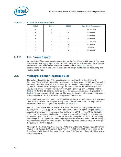
Table 2-2. BSEL[2:0] Frequency Table<br />
2.4.2 PLL Power Supply<br />
18<br />
<strong>Dual</strong>-<strong>Core</strong> <strong>Intel®</strong> <strong>Xeon®</strong> <strong>Processor</strong> <strong>5200</strong> <strong>Series</strong> Electrical Specifications<br />
BSEL2 BSEL1 BSEL0 Bus Clock Frequency<br />
0 0 0 266.66 MHz<br />
0 0 1 Reserved<br />
0 1 0 Reserved<br />
0 1 1 Reserved<br />
1 0 0 333.33 MHz<br />
1 0 1 Reserved<br />
1 1 0 400 MHz<br />
1 1 1 Reserved<br />
An on-die PLL filter solution is implemented on the <strong>Dual</strong>-<strong>Core</strong> <strong>Intel®</strong> <strong>Xeon®</strong> <strong>Processor</strong><br />
<strong>5200</strong> <strong>Series</strong>. The V CCPLL input is used for this configuration in <strong>Dual</strong>-<strong>Core</strong> <strong>Intel®</strong> <strong>Xeon®</strong><br />
<strong>Processor</strong> <strong>5200</strong> <strong>Series</strong>-based platforms. Please refer to Table 2-12 for DC<br />
specifications. Refer to the appropriate platform design guidelines for decoupling and<br />
routing guidelines.<br />
2.5 Voltage Identification (VID)<br />
The Voltage Identification (VID) specification for the <strong>Dual</strong>-<strong>Core</strong> <strong>Intel®</strong> <strong>Xeon®</strong><br />
<strong>Processor</strong> <strong>5200</strong> <strong>Series</strong> is defined by the Voltage Regulator Module (VRM) and Enterprise<br />
Voltage Regulator-Down (EVRD) 11.0 Design Guidelines. The voltage set by the VID<br />
signals is the reference VR output voltage to be delivered to the processor Vcc pins.<br />
VID signals are open drain outputs, which must be pulled up to V TT. Please refer to<br />
Table 2-15 for the DC specifications for these signals. A voltage range is provided in<br />
Table 2-12 and changes with frequency. The specifications have been set such that one<br />
voltage regulator can operate with all supported frequencies.<br />
Individual processor VID values may be calibrated during manufacturing such that two<br />
devices at the same core frequency may have different default VID settings. This is<br />
reflected by the VID range values provided in Table 2-3.<br />
The <strong>Dual</strong>-<strong>Core</strong> <strong>Intel®</strong> <strong>Xeon®</strong> <strong>Processor</strong> <strong>5200</strong> <strong>Series</strong> uses six voltage identification<br />
signals, VID[6:1], to support automatic selection of power supply voltages. Table 2-3<br />
specifies the voltage level corresponding to the state of VID[6:1]. A ‘1’ in this table<br />
refers to a high voltage level and a ‘0’ refers to a low voltage level. If the processor<br />
socket is empty (VID[6:1] = 111111), or the voltage regulation circuit cannot supply<br />
the voltage that is requested, the voltage regulator must disable itself. See the Voltage<br />
Regulator Module (VRM) and Enterprise Voltage Regulator-Down (EVRD) 11.0 Design<br />
Guidelines for further details.<br />
Although the Voltage Regulator Module (VRM) and Enterprise Voltage Regulator-Down<br />
(EVRD) 11.0 Design Guidelines defines VID[7:0], VID7 and VID0 are not used on the<br />
<strong>Dual</strong>-<strong>Core</strong> <strong>Intel®</strong> <strong>Xeon®</strong> <strong>Processor</strong> <strong>5200</strong> <strong>Series</strong>; VID7 is always hard wired low at the<br />
voltage regulator.