Dual-Core Intel® Xeon® Processor 5200 Series
Dual-Core Intel® Xeon® Processor 5200 Series
Dual-Core Intel® Xeon® Processor 5200 Series

You also want an ePaper? Increase the reach of your titles
YUMPU automatically turns print PDFs into web optimized ePapers that Google loves.
.<br />
30<br />
<strong>Dual</strong>-<strong>Core</strong> <strong>Intel®</strong> <strong>Xeon®</strong> <strong>Processor</strong> <strong>5200</strong> <strong>Series</strong> Electrical Specifications<br />
10. This specification refers to the total reduction of the load line due to VID transitions below the specified<br />
VID.<br />
11. Individual processor VID values may be calibrated during manufacturing such that two devices at the same<br />
frequency may have different VID settings.<br />
12. This specification applies to the VCCPLL land.<br />
13. Baseboard bandwidth is limited to 20 MHz.<br />
14. I CC_TDC is the sustained (DC equivalent) current that the processor is capable of drawing indefinitely and<br />
should be used for the voltage regulator temperature assessment. The voltage regulator is responsible for<br />
monitoring its temperature and asserting the necessary signal to inform the processor of a thermal<br />
excursion. Please see the applicable design guidelines for further details. The processor is capable of<br />
drawing I CC_TDC indefinitely. Refer to Figure 2-1 for further details on the average processor current draw<br />
over various time durations. This parameter is based on design characterization and is not tested.<br />
15. This is the maximum total current drawn from the V TT plane by only one processor with R TT enabled. This<br />
specification does not include the current coming from on-board termination (R TT), through the signal line.<br />
Refer to the appropriate platform design guide and the Voltage Regulator Design Guidelines to determine<br />
the total I TT drawn by the system. This parameter is based on design characterization and is not tested.<br />
16. I CC_VTT_OUT is specified at 1.1 V.<br />
17. I CC_RESET is specified while PWRGOOD and RESET# are asserted.<br />
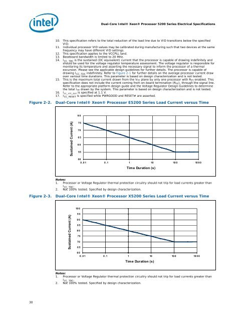
Figure 2-2. <strong>Dual</strong>-<strong>Core</strong> <strong>Intel®</strong> <strong>Xeon®</strong> <strong>Processor</strong> E<strong>5200</strong> <strong>Series</strong> Load Current versus Time<br />
Sustained Current (A)<br />
80<br />
75<br />
70<br />
65<br />
60<br />
55<br />
50<br />
0.01 0.1 1 10 100 1000<br />
Time Duration (s)<br />
Notes:<br />
1. <strong>Processor</strong> or Voltage Regulator thermal protection circuitry should not trip for load currents greater than<br />
I CC_TDC .<br />
2. Not 100% tested. Specified by design characterization.<br />
Figure 2-3. <strong>Dual</strong>-<strong>Core</strong> <strong>Intel®</strong> <strong>Xeon®</strong> <strong>Processor</strong> X<strong>5200</strong> <strong>Series</strong> Load Current versus Time<br />
Sustained Current (A)<br />
10 0<br />
95<br />
90<br />
85<br />
80<br />
75<br />
70<br />
65<br />
60<br />
0.01 0.1 1 10 100 1000<br />
Time Duration (s)<br />
Notes:<br />
1. <strong>Processor</strong> or Voltage Regulator thermal protection circuitry should not trip for load currents greater than<br />
I CC_TDC.<br />
2. Not 100% tested. Specified by design characterization.