2001 ASD/LRFD Wind/Seismic Supplement - American Wood Council
2001 ASD/LRFD Wind/Seismic Supplement - American Wood Council
2001 ASD/LRFD Wind/Seismic Supplement - American Wood Council
- No tags were found...
Create successful ePaper yourself
Turn your PDF publications into a flip-book with our unique Google optimized e-Paper software.
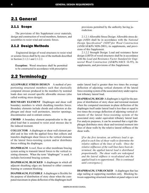
4 GENERAL DESIGN REQUIREMENTS2.1 General2.1.1 ScopeThe provisions of this <strong>Supplement</strong> cover materials,design and construction of wood members, fasteners, andassemblies to resist wind and seismic forces.2.1.2 Design MethodsEngineered design of wood structures to resist windor seismic forces shall be by one of the methods describedin Section 2.1.2.1 and 2.1.2.2.Exception: <strong>Wood</strong> structures shall be permittedto be constructed in accordance with prescriptiveprovisions permitted by the authority having jurisdiction.2.1.2.1 Allowable Stress Design: Allowable stress design(<strong>ASD</strong>) shall be in accordance with the NationalDesign Specification ® (NDS ® )for <strong>Wood</strong> Construction(ANSI/AF&PA NDS-<strong>2001</strong>), its supplements, and provisionsof this <strong>Supplement</strong>.2.1.2.2 Strength Design: Load and resistance factordesign (<strong>LRFD</strong>) of wood structures shall be in accordancewith the Load and Resistance Factor Standard for Engineered<strong>Wood</strong> Construction (AF&PA/ASCE 16-95), itssupplements, and provisions of this <strong>Supplement</strong>.2.2 TerminologyALLOWABLE STRESS DESIGN A method of proportioningstructural members such that elasticallycomputed stresses produced in the members by nominalloads does not exceed specific allowable stresses (alsocalled working stress design).BOUNDARY ELEMENT Diaphragm and shear wallboundary members to which sheathing transfers forces.Boundary elements include chords and collectors at diaphragmand shear wall perimeters, interior openings,discontinuities and re-entrant corners.CHORD A boundary element perpendicular to the appliedload that is assumed to resist axial stresses due tothe induced moment.COLLECTOR A diaphragm or shear wall element paralleland in line with the applied force that collects andtransfers diaphragm shear forces to the vertical elementsof the lateral force-resisting system and/or distributesforces withing the diaphragm.DIAPHRAGM A roof, floor or other membrane bracingsystem acting to transmit lateral forces to the vertical resistingelements. When the term “diaphragm” is used, itincludes horizontal bracing systems.DIAPHRAGM, BLOCKED A diaphragm in which alladjacent sheathing edges are fastened to either commonframing or common blocking.DIAPHRAGM, FLEXIBLE A diaphragm is flexible forthe purpose of distribution of story shear when the computedmaximum in-plane deflection of the diaphragm itselfunder lateral load is greater than two times the averagedeflection of adjoining vertical elements of the lateralforce-resisting system of the associated story under equivalenttributary lateral load.DIAPHRAGM, RIGID A diaphragm is rigid for the purposeof distribution of story shear and torsional momentwhen the computed maximum in-plane deflection of thediaphragm itself under lateral load is less than or equal totwo times the average deflection of adjoining vertical elementsof the lateral force-resisting system of theassociated story under equivalent tributary lateral load.For analysis purposes, it can be assumed that a rigid diaphragmdistributes story shear and torsional moment intolines of shear walls by the relative lateral stiffness of theshear walls.[For the first iteration, an arbitrary load is appliedto each line of shear walls to determine therelative stiffness of the lines of walls. Once therelative stiffnesses of the wall lines have been determined,the applied lateral load is distributedproportionally. The shear walls are redesignedand the lateral stiffness is recalculated and theapplied load is re-apportioned. This is continueduntil convergence.]DIAPHRAGM, UNBLOCKED A diaphragm that hasedge nailing at supporting members only. Blocking betweensupporting structural members at panel edges is notAMERICAN WOOD COUNCIL


