2001 ASD/LRFD Wind/Seismic Supplement - American Wood Council
2001 ASD/LRFD Wind/Seismic Supplement - American Wood Council
2001 ASD/LRFD Wind/Seismic Supplement - American Wood Council
- No tags were found...
Create successful ePaper yourself
Turn your PDF publications into a flip-book with our unique Google optimized e-Paper software.
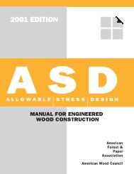
<strong>2001</strong> EDITIONSUPPLEMENTSpecial DesignProvisions for<strong>Wind</strong> and <strong>Seismic</strong><strong>ASD</strong>/<strong>LRFD</strong>ALLOWABLE STRESSDESIGNLOAD AND RESISTANCEFACTOR DESIGNMANUAL FOR ENGINEEREDWOOD CONSTRUCTION<strong>American</strong>Forest &PaperAssociation<strong>American</strong> <strong>Wood</strong> <strong>Council</strong>
<strong>2001</strong> EDITIONSUPPLEMENTSpecial DesignProvisions for<strong>Wind</strong> and <strong>Seismic</strong><strong>ASD</strong>/<strong>LRFD</strong>ALLOWABLE STRESSDESIGNLOAD AND RESISTANCEFACTOR DESIGNMANUAL FOR ENGINEEREDWOOD CONSTRUCTIONCopyright © <strong>2001</strong><strong>American</strong> Forest & Paper Association, Inc.
<strong>ASD</strong>/<strong>LRFD</strong> SUPPLEMENT – SPECIAL DESIGN PROVISIONS FOR WIND AND SEISMICTable of ContentsChapter/TitlePageChapter/TitlePage1 Designer Flowchart ..................................................11.1 Flowchart2 General Design Requirements .. 32.1 General2.2 Terminology2.3 Notation4 Lateral Force-ResistingSystems .............................................................................................. 114.1 General4.2 <strong>Wood</strong> Diaphragms4.3 <strong>Wood</strong> Shear Walls5 References .................................................................................293 Members and Connections .................73.1 Framing3.2 Sheathing3.3 ConnectionsList of Tables3.1.1.1 Wall Stud Bending Stress Increase Factors ..........83.2A Nominal Uniform Load Capacities, psf,for Wall Sheathing Resisting <strong>Wind</strong> Loads .............93.2B Nominal Uniform Load Capacities, psf,for Roof Sheathing Resisting <strong>Wind</strong> Loads ........ 104.2.4 Maximum Diaphragm Aspect Ratios(Horizontal or Sloped Diaphragms) .......................... 134.2A Nominal Unit Shear Values for <strong>Wood</strong>-FrameDiaphragms (Blocked <strong>Wood</strong> Structural PanelDiaphragms) ............................................................................................ 164.2B Nominal Unit Shear Values for <strong>Wood</strong>-FrameDiaphragms (Unblocked <strong>Wood</strong> StructuralPanel Diaphragms) .......................................................................... 174.2C Nominal Unit Shear Values for <strong>Wood</strong>-FrameDiaphragms (Lumber Diaphragms) ........................... 184.3.3.4 Shear Capacity Adjustment Factor, C o ................... 204.3.4 Maximum Shear Wall Aspect Ratios ........................ 214.3A Nominal Unit Shear Values for <strong>Wood</strong>-FrameShear Walls (<strong>Wood</strong>-based Sheathing) ..................... 254.3B Nominal Unit Shear Values for <strong>Wood</strong>-FrameShear Walls (Gypsum and Cement Plaster) ..... 264.3C Nominal Unit Shear Values for <strong>Wood</strong>-FrameShear Walls (Lumber Shear Walls) ............................. 27AMERICAN FOREST & PAPER ASSOCIATION
<strong>ASD</strong>/<strong>LRFD</strong> SUPPLEMENT – SPECIAL DESIGN PROVISIONS FOR WIND AND SEISMIC11DESIGNERFLOWCHART1.1 Flowchart 2AMERICAN FOREST & PAPER ASSOCIATION
<strong>ASD</strong>/<strong>LRFD</strong> SUPPLEMENT – SPECIAL DESIGN PROVISIONS FOR WIND AND SEISMIC3GENERALDESIGNREQUIREMENTS22.1 General 42.2 Terminology 42.3 Notation 5AMERICAN FOREST & PAPER ASSOCIATION
4 GENERAL DESIGN REQUIREMENTS2.1 General2.1.1 ScopeThe provisions of this <strong>Supplement</strong> cover materials,design and construction of wood members, fasteners, andassemblies to resist wind and seismic forces.2.1.2 Design MethodsEngineered design of wood structures to resist windor seismic forces shall be by one of the methods describedin Section 2.1.2.1 and 2.1.2.2.Exception: <strong>Wood</strong> structures shall be permittedto be constructed in accordance with prescriptiveprovisions permitted by the authority having jurisdiction.2.1.2.1 Allowable Stress Design: Allowable stress design(<strong>ASD</strong>) shall be in accordance with the NationalDesign Specification ® (NDS ® )for <strong>Wood</strong> Construction(ANSI/AF&PA NDS-<strong>2001</strong>), its supplements, and provisionsof this <strong>Supplement</strong>.2.1.2.2 Strength Design: Load and resistance factordesign (<strong>LRFD</strong>) of wood structures shall be in accordancewith the Load and Resistance Factor Standard for Engineered<strong>Wood</strong> Construction (AF&PA/ASCE 16-95), itssupplements, and provisions of this <strong>Supplement</strong>.2.2 TerminologyALLOWABLE STRESS DESIGN A method of proportioningstructural members such that elasticallycomputed stresses produced in the members by nominalloads does not exceed specific allowable stresses (alsocalled working stress design).BOUNDARY ELEMENT Diaphragm and shear wallboundary members to which sheathing transfers forces.Boundary elements include chords and collectors at diaphragmand shear wall perimeters, interior openings,discontinuities and re-entrant corners.CHORD A boundary element perpendicular to the appliedload that is assumed to resist axial stresses due tothe induced moment.COLLECTOR A diaphragm or shear wall element paralleland in line with the applied force that collects andtransfers diaphragm shear forces to the vertical elementsof the lateral force-resisting system and/or distributesforces withing the diaphragm.DIAPHRAGM A roof, floor or other membrane bracingsystem acting to transmit lateral forces to the vertical resistingelements. When the term “diaphragm” is used, itincludes horizontal bracing systems.DIAPHRAGM, BLOCKED A diaphragm in which alladjacent sheathing edges are fastened to either commonframing or common blocking.DIAPHRAGM, FLEXIBLE A diaphragm is flexible forthe purpose of distribution of story shear when the computedmaximum in-plane deflection of the diaphragm itselfunder lateral load is greater than two times the averagedeflection of adjoining vertical elements of the lateralforce-resisting system of the associated story under equivalenttributary lateral load.DIAPHRAGM, RIGID A diaphragm is rigid for the purposeof distribution of story shear and torsional momentwhen the computed maximum in-plane deflection of thediaphragm itself under lateral load is less than or equal totwo times the average deflection of adjoining vertical elementsof the lateral force-resisting system of theassociated story under equivalent tributary lateral load.For analysis purposes, it can be assumed that a rigid diaphragmdistributes story shear and torsional moment intolines of shear walls by the relative lateral stiffness of theshear walls.[For the first iteration, an arbitrary load is appliedto each line of shear walls to determine therelative stiffness of the lines of walls. Once therelative stiffnesses of the wall lines have been determined,the applied lateral load is distributedproportionally. The shear walls are redesignedand the lateral stiffness is recalculated and theapplied load is re-apportioned. This is continueduntil convergence.]DIAPHRAGM, UNBLOCKED A diaphragm that hasedge nailing at supporting members only. Blocking betweensupporting structural members at panel edges is notAMERICAN WOOD COUNCIL
6 GENERAL DESIGN REQUIREMENTSG aG ac= Apparent diaphragm shear stiffness from nailslip and panel shear deformation, kips/in. (fromColumn A, Table 4.2).= Combined apparent shear wall shear stiffnessof two-sided shear wall, kips/in.2. The maximum clear height from top ofdiaphragm to bottom of diaphragm framingabove.t = Uniform uplift force, lbs./ft.ν = Induced unit shear, lbs./ft.G a1= Apparent shear wall shear stiffness for side 1,kips/in. (from Column A, Table 4.3).G a2= Apparent shear wall shear stiffness for side 2,kips/in. (from Column A, Table 4.3).ν sν maxν scK min= Minimum ratio of v 1/G a1or v 2/G a2= Nominal unit shear capacity for seismic design,lbs./ft.= Maximum induced unit shear force, lbs./ft.= Combined nominal unit shear capacity of twosidedshear wall for seismic design, lbs./ft.L = The dimension of a diaphragm perpendicular tothe direction of application of force. For openfrontstructures, L is the length from the edge ofthe diaphragm at the open front to the verticalresisting elements parallel to the direction ofthe applied force.ν s1ν s2ν w= Nominal unit shear capacity for side 1, lbs./ft.(from Column A, Table 4.3).= Nominal unit shear capacity for side 2, lbs./ft.(from Column A, Table 4.3).= Nominal unit shear capacity for wind design,lbs./ftL c= The length of the cantilever for a cantileverν wc= Combined nominal unit shear capacity of two-diaphragm, ft. (see figure 4.2.5.2)sided shear wall for wind design, lbs./ft.ΣL i= Sum of perforated shear wall segment lengths,ft.x = Distance from chord splice to nearest support,in.R = Response modification coefficientT = Tension chord force, lbs.V = Induced shear force in perforated shear wall,lbs.W = Diaphragm width, ft.W = The width of a diaphragm in the direction ofapplication of force measured as the sheatheddimension of the diaphragm.b = The length of a shear wall or shearwall segmentmeasured as the sheathed dimension of theshear wall.∆ c∆ aδ diaδ swφ b= Diaphragm chord splice slip at the induced unitshear in diaphragm, in.= Total vertical elongation of wall anchoragesystem (including fastener slip, deviceelongation, rod elongation, etc) at the inducedunit shear in the shear wall, in.= Maximum diaphragm deflection determined byelastic analysis, in.= Maximum shear wall deflection determined byelastic analysis, in.= Sheathing resistance factor for out of planeb s= Shear wall length for determining apect ratio.bendingFor perforated shearwalls, use the minimumshearwall segment length included in the L i , ft.h = The height of a shear wall or shearwall segmentmeasured as:1. The maximum clear height from top offoundation to bottom of diaphragm framingabove orφ DΩ 0= Sheathing resistance factor for in-plane shearof shearwalls and diaphragms= System overstrength factorAMERICAN WOOD COUNCIL
<strong>ASD</strong>/<strong>LRFD</strong> SUPPLEMENT – SPECIAL DESIGN PROVISIONS FOR WIND AND SEISMIC7MEMBERS ANDCONNECTIONS33.1 Framing 83.2 Sheathing 83.3 Connections 10Table 3.1.1.1 Wall Stud Bending Stress Increase Factors ..... 8Table 3.2ATable 3.2BNominal Uniform Load Capacities, psf, forWall Sheathing Resisting <strong>Wind</strong> Loads.............. 9Nominal Uniform Load Capacities, psf, forRoof Sheathing Resisting <strong>Wind</strong> Loads ........... 10AMERICAN FOREST & PAPER ASSOCIATION
8 MEMBERS AND CONNECTIONS3.1 Framing3.1.1 Wall FramingIn addition to gravity loads, wall framing shall bedesigned to resist induced wind and seismic forces. Theframing shall be designed using methods referenced in2.1.2.1 for allowable stress design (<strong>ASD</strong>) and 2.1.2.2 forstrength design (<strong>LRFD</strong>).3.1.1.1 Wall Stud Bending Stress Increase: The bendingstress for sawn lumber wood studs resisting out ofplane wind loads shall be permitted to be increased by thefactors in Table 3.1.1.1, in lieu of the 1.15 repetitive memberfactor, to take into consideration the load sharing andcomposite action provided by wood structural panelsheathing. The factor applies when studs are designed forbending, spaced no more than 16 inches on center, coveredon the inside with a minimum of ½-inch gypsumwallboard, and sheathed on the exterior with a minimumof 3/8-inch wood structural panel sheathing that is attachedto the studs using a minimum of 8d common nails spaced amaximum of 6 inches o.c. at panel edges and 12 inches o.c.at intermediate framing members.3.1.2 Floor FramingIn addition to gravity loads, floor framing shall bedesigned to resist induced wind and seismic forces. Theframing shall be designed using methods referenced in2.1.2.1 for allowable stress design (<strong>ASD</strong>) and 2.1.2.2 forstrength design (<strong>LRFD</strong>).3.1.3 Roof FramingIn addition to gravity loads, roof framing shall be designedto resist induced wind and seismic forces. Theframing shall be designed using methods referenced in2.1.2.1 for allowable stress design (<strong>ASD</strong>) and 2.1.2.2 forstrength design (<strong>LRFD</strong>).Table 3.1.1.1Wall Stud BendingStress Increase FactorsStud SizeSystem Factor2x4 1.52x6 1.42x8 1.32x10 1.22x12 1.153.2 Sheathing3.2.1 Wall SheathingExterior wall sheathing and its fasteners shall be capableof resisting and transferring out of plane wind loadsto the wall framing. Maximum spans and nominal uniformload capacities for wall sheathing materials are givenin Table 3.2A. The <strong>ASD</strong> allowable uniform load capacitiesto be used for wind design shall be determined bydividing the nominal uniform load capacities by a safetyfactor of 1.6. The <strong>LRFD</strong> factored uniform load capacitiesto be used for wind design shall be determined by multiplyingthe nominal uniform load capacities by a resistancefactor, φ b , of 0.85. Sheathing used in shear wall assem-blies to resist lateral forces shall be designed in accordancewith 4.3.3.2.2 Floor SheathingFloor sheathing shall be capable of resisting and transferringgravity loads to the floor framing. Sheathing usedin diaphragm assemblies to resist lateral forces shall bedesigned in accordance with 4.2.AMERICAN WOOD COUNCIL
<strong>ASD</strong>/<strong>LRFD</strong> SUPPLEMENT – SPECIAL DESIGN PROVISIONS FOR WIND AND SEISMIC9Table 3.2A Nominal Uniform Load Capacities, psf, for Wall Sheathing Resisting<strong>Wind</strong> Loads 1Sheathing Type 3 Span Rating or Grade MinimumThickness(in.)Sheathing Long Dimension Orientation:Perpendicular to SupportsMaximumStud Spacing(in.)Actual StudSpacing (in.)Parallel to SupportsMaximumStud Spacing(in.)Actual StudSpacing (in.)12 16 24 12 16 243<strong>Wood</strong> Structural Panels 4(Sheathing Grades, C-C,C-D, C-C Plugged, OSB)Particleboard Sheathing(M-S Exterior Glue)Particleboard PanelSiding(M-S Exterior Glue)Hardboard Siding(Direct to Studs)24/024/1632/1640/2048/24Lap SidingShiplap Edge Panel SidingSquare Edge Panel Siding3/87/1615/3219/3223/323/81/25/83/47/167/167/16242424242416161624162424Nominal UniformLoads (psf)4255406259501160240305355595805105135155265360(contactmanufacturer)(contactmanufacturer)460460460260260260-115115242424242416161624-2424Nominal UniformLoads (psf)90110155255380506090145215–25 240 265 290 2(contactmanufacturer)(contactmanufacturer)-460460-260260-115115MEMBERS AND CONNECTIONSCellulosic FiberboardSheathingRegularStructuralStructural1/21/225/321. Nominal capacities shall be adjusted in accordance with Section 3.2.1 to determine <strong>ASD</strong> uniform load capacity and <strong>LRFD</strong> uniform resistances.2. Sheathing shall be OSB or plywood with 4 or more plies.3. <strong>Wood</strong> structural panels shall conform to the requirements for its type in DOC PS 1 or PS2. Particleboard sheathing shall conform to ANSI A208.1.Hardboard panel and siding shall conform to the requirements of AHA A135.5 or AHA A135.4 as applicable. Cellulosic fiberboard sheathing shallconform to AHA A194.1 or ASTM C208.4. Tabulated values are for maximum bending loads from wind. Loads are limited by bending or shear stress assuming a 2-span continuous condition.For more information, see the <strong>ASD</strong> <strong>Wood</strong> Structural Panels <strong>Supplement</strong>.------------16161690135165507590---AMERICAN FOREST & PAPER ASSOCIATION
10 MEMBERS AND CONNECTIONS3.2.3 Roof SheathingRoof sheathing and its fasteners shall be capable ofresisting and transferring out of plane wind and gravityloads to the roof framing. Maximum spans and nominaluniform load capacities for roof sheathing materials aregiven in Table 3.2B. The <strong>ASD</strong> allowable uniform loadcapacities to be used for out of plane wind design shall bedetermined by dividing the nominal uniform load capacitiesby a safety factor of 1.6. The <strong>LRFD</strong> factored uniformload capacities to be used for wind design shall be determinedby multiplying the nominal uniform load capacitiesby a resistance factor, φ b , of 0.85. Sheathing used in diaphragmassemblies to resist lateral forces shall be designedin accordance with 4.2.Table 3.2B Nominal Uniform Load Capacities, psf, for Roof Sheathing Resisting<strong>Wind</strong> Loads 1Sheathing Type Span Rating or Grade MinimumThickness(in.)Sheathing Long Dimension AppliedPerpendicular to SupportsRafter/Truss Spacing (in.)<strong>Wood</strong> Structural Panels 2,3(Sheathing Grades, C-C,C-D, C-C Plugged, OSB)<strong>Wood</strong> Structural Panels 2,3(Single Floor Grades,Underlayment, C-CPlugged)24/024/1632/1640/2048/2416 o.c.20 o.c.24 o.c.32 o.c.48 o.c.3/87/1615/3219/3223/3219/3219/3223/327/81-3/3212 16 19.2 244255406259501160705815108513901790Nominal Uniform Loads (psf)240305355595805395455610830129516521024541556027532042557510601. Nominal capacities shall be adjusted in accordance with Section 3.2.3 to determine <strong>ASD</strong> uniform load capacity and<strong>LRFD</strong> uniform resistances.2. <strong>Wood</strong> structural panels shall conform to the requirements for its type in DOC PS 1 or PS2.3. Tabulated values are for maximum bending loads from wind. Loads are limited by bending or shear stress assuming a 2-span continuous condition. For more information, see the <strong>ASD</strong> <strong>Wood</strong> Structural Panels <strong>Supplement</strong>.1051351552653601752052703706803.3 ConnectionsDecember 15, <strong>2001</strong>3.3.1 ConnectionsConnections resisting induced wind and seismic forcesshall be designed in accordance with methods referencedin 2.1.2.1 for allowable stress design (<strong>ASD</strong>) and 2.1.2.2for strength design (<strong>LRFD</strong>).AMERICAN WOOD COUNCIL
<strong>ASD</strong>/<strong>LRFD</strong> SUPPLEMENT – SPECIAL DESIGN PROVISIONS FOR WIND AND SEISMIC11LATERALFORCE-RESISTINGSYSTEMS44.1 General 124.2 <strong>Wood</strong> Diaphragms 134.3 <strong>Wood</strong> Shear Walls 19Table 4.2.4Table 4.2A-CMaximum Diaphragm Aspect Ratios(Horizontal or Sloped Diaphragms) ............ 13Nominal Unit Shear Values for <strong>Wood</strong>-Frame Diaphragms:A = Blocked Diaphragms ........................... 16B = Unblocked Diaphragms ...................... 17C = Lumber Diaphragms .......................... 18Table 4.3.3.4 Shear Capacity Adjustment Factor, C o ....... 20Table 4.3.4 Maximum Shear Wall Aspect Ratios ........... 21Table 4.3A-CNominal Unit Shear Values for <strong>Wood</strong>-Frame Shear Walls:A = <strong>Wood</strong>-based Sheathing........................ 25B = Gypsum and Cement Plaster ............. 26C = Lumber Shear Walls ........................... 27AMERICAN FOREST & PAPER ASSOCIATION
<strong>ASD</strong>/<strong>LRFD</strong> SUPPLEMENT – SPECIAL DESIGN PROVISIONS FOR WIND AND SEISMIC134.2 <strong>Wood</strong> Diaphragms4.2.1 Application Requirements<strong>Wood</strong> diaphragms are permitted to be used to resisthorizontal forces provided the deflection in the plane ofthe diaphragm, as determined by calculations, tests, oranalogies drawn therefrom, does not exceed the permissibledeflection of attached load distributing or resistingelements. Connections and blocking shall extend into thediaphragm a sufficient distance to develop the force transferredinto the diaphragm.4.2.2 DeflectionPermissible deflection shall be that deflection up towhich the diaphragm and any attached load distributingor resisting element will maintain its structural integrityunder design load conditions, such that the resisting elementwill continue to support design loads without dangerto occupants of the structure.Calculations of diaphragm deflection shall accountfor bending and shear deflections, fastener deformation,chord splice slip, and other contributing sources of deflection.The midspan diaphragm deflection, δ dia , is permittedto be calculated by use of the following equation:( x∆)35νL0.25νL∑ cδdia= + + (4.2-1)8EAW 1000G 2Wwhere:aE = Modulus of elasticity of diaphragm chords, psiA = Area of chord cross-section, in. 2G a= Apparent diaphragm shear stiffness from nailslip and panel shear deformation, kips/in. (fromColumn A, Table 4.2)L = Diaphragm length, ft.ν = Induced unit shear in diaphragm, lbs./ft.W = Diaphragm width, ft.x = Distance from chord splice to nearest support,∆ cδ diain.= Diaphragm chord splice slip at the induced unitshear in diaphragm, in.= Maximum diaphragm deflection determined byelastic analysis, in.Alternatively, for wood structural panel diaphragms,deflection is permitted to be calculated using a rationalanalysis where apparent shear stiffness accounts for panelshear deformation and non-linear nail slip in the sheathingto framing connection.4.2.3 Shear CapacitiesThe nominal unit shear capacities for seismic designare provided in Column A of Tables 4.2A, B, and C andfor wind design in Column B of Tables 4.2A, B, and C.The <strong>ASD</strong> allowable unit shear capacity shall be determinedby dividing the nominal unit shear capacity by asafety factor of 2.0. No further increases shall be permitted.The <strong>LRFD</strong> factored unit resistance shall bedetermined by multiplying the nominal unit shear capacityby a resistance factor, φ D , of 0.65.4.2.4 Diaphragm Aspect RatiosSize and shape of diaphragms shall be limited to theaspect ratios in Table 4.2.4.Table 4.2.4Maximum DiaphragmAspect Ratios(Horizontal or Sloped Diaphragms)DiaphragmMaximumSheathing TypeL/W Ratio<strong>Wood</strong> structural panel, unblocked 3:1<strong>Wood</strong> structural panel, blocked 4:1Single-layer straight lumber sheathing 2:1Single-layer diagonal lumber sheathing 3:1Double-layer diagonal lumber sheathing 4:14.2.5 Horizontal Distribution ofShearDiaphragms shall be defined as rigid or flexible forthe purposes of distributing shear loads and designing fortorsional moments. When a diaphragm is defined as flexible,the diaphragm shear forces shall be distributed to thevertical resisting elements based on tributary area. Whena diaphragm is defined as rigid, the diaphragm shear forcesshall be distributed based on the relative lateral stiffnessesof the vertical resisting elements for the story below.4.2.5.1 Torsional Irregularity: Structures with rigidwood diaphragms shall be considered as torsionally ir-4LATERAL FORCE-RESISTING SYSTEMSAMERICAN FOREST & PAPER ASSOCIATION
14 LATERAL FORCE-RESISTING SYSTEMSregular when the maximum story drift, computed includingaccidental torsion, at one end of the structure is morethan 1.2 times the average of the story drifts at the twoends of the structure. Where torsional irregularity exists,diaphragms shall meet the following requirements:1. The diaphragm conforms to 4.2.7.1 - 4.2.7.3.2. The L/W ratio of the diaphragm is less than1:1 for one-story structures or 1:1½ for structuresover one story in height.Exception: Where calculations show that diaphragmdeflections can be tolerated, the length, L,shall be permitted to be increased to an L/W rationot greater than 1½:1 when sheathed in conformancewith 4.2.7.1 or to 1:1 when sheathed inconformance with 4.2.7.2 or 4.2.7.3.4.2.5.1.1 Open Front Structures: Open front structuresutilizing rigid wood diaphragms to distribute shearforces through torsion shall be permitted provided:1. The diaphragm length, L, (normal to the openside) does not exceed 25 feet.2. The L/W ratio (as shown in Figure 4.2.5.1)of the diaphragm is less than 1:1 for one-storystructures or 1:1½ for structures over one storyin height.Exception: Where calculations show that diaphragmdeflections can be tolerated, the length, L,(normal to the open side) shall be permitted to beincreased to an L/W ratio not greater than 1½:1when sheathed in conformance with 4.2.7.1 or4.2.7.3 or to 1:1 when sheathed in conformancewith 4.2.7.2.Figure 4.2.5.1 Open Front BuildingForceLShear WallsWPlan ViewOpen Fronton Building4.2.5.2 Cantilevered Diaphragms: Rigid wood diaphragmsshall be permitted to cantilever past the outermostsupporting shear wall (or other vertical resisting element)a distance, L c , of not more than 25 feet or two thirds of thediaphragm width, W, whichever is smaller. Figure 4.2.5.2illustrates the dimensions of L c and W for a cantilevereddiaphragm.Figure 4.2.5.2 Cantilevered DiaphragmForceShear WallsWPlan ViewCantileveredDiaphragmLc4.2.6 Construction Requirements4.2.6.1 Framing Requirements: Diaphragm boundaryelements shall be provided to transmit the design tension,compression and shear forces. Diaphragm sheathing shallnot be used to splice boundary elements. Diaphragmchords and collectors shall be placed in, or in contact with,the plane of the diaphragm framing unless it can be demonstratedthat the moments, shears, and deflections,considering eccentricities resulting from other configurations,can be tolerated without exceeding the framingcapacity and drift limits.4.2.6.2 Sheathing: Diaphragms shall be sheathed withapproved materials. Details on sheathing types and thicknessesfor commonly used floor, roof and ceilingdiaphragm assemblies are provided in 4.2.7 and Tables4.2A, B, and C.4.2.6.3 Fasteners: Sheathing shall be attached to framingusing approved fasteners and/or adhesives. Nails orother approved sheathing connectors shall be driven flushwith the surface of the sheathing. Details on type, size,and spacing of mechanical fasteners for typical floor, roof,and ceiling diaphragm assemblies are provided in 4.2.7and Tables 4.2A, B, and C.4.2.7 Diaphragm Assemblies4.2.7.1 <strong>Wood</strong> Structural Panel Diaphragms: Diaphragmssheathed with wood structural panel sheathingshall be permitted to be used to resist seismic and windforces. <strong>Wood</strong> structural panel sheathing used for diaphragmsthat are part of the lateral force-resisting systemshall be applied directly to the framing members.Exception: <strong>Wood</strong> structural panel sheathing in adiaphragm is permitted to be fastened over solidlumber planking or laminated decking providedthe panel joints and lumber planking or laminatedAMERICAN WOOD COUNCIL
<strong>ASD</strong>/<strong>LRFD</strong> SUPPLEMENT – SPECIAL DESIGN PROVISIONS FOR WIND AND SEISMIC15decking joints do not coincide. In addition, adjacentpanel edges shall be fastened to a commonmember and fasteners shall not be spaced less than3/8 inches from the edges of panels or joints inthe substrate.Where diaphragms are designated as blocked, all jointsin sheathing shall occur over and be fastened to commonframing members. The size and spacing of fasteners atwood diaphragm boundaries, panel edges, and intermediatesupports shall be as prescribed in Tables 4.2A and B.The diaphragm shall be constructed as follows:1. Panels not less than 4 ft. x 8 ft. except at endswhere reduced widths are permitted.2. Nails spaced not less than 3/8 inches from edgesand ends of panels and framing. Maximum nailspacing of 6 inches along intermediate framingmembers when supports are spaced 48 incheso.c. Maximum nail spacing along intermediateframing of 12 inches for other conditions.3. 2x nominal or wider framing at adjoiningpanel edges except that 3x nominal or widerframing and staggered nailing are requiredwhere:a) nails are spaced 2 inches o.c. or 2 ½inches o.c., orb) 10d nails having penetration into framingof more than 1-1/2 in. are spaced 3inches o.c. or less4. <strong>Wood</strong> structural panels shall conform to therequirements for its type in DOC PS1 or PS2.4.2.7.2 Diaphragms Diagonally Sheathed with Single-Layer of Lumber: Single diagonally sheathed lumberdiaphragms are permitted to be used to resist seismic andwind forces. Single diagonally sheathed lumber diaphragmsshall be constructed of minimum 1-inch thicknominal sheathing boards or 2-inch thick nominal lumberlaid at an angle of approximately 45° to the supports. Endjoints in adjacent boards shall be separated by at least onejoist space and there shall be at least two boards betweenjoints on the same support. Nailing of diagonally sheathedlumber diaphragms shall be in accordance with Table 4.2C.Single diagonally sheathed lumber diaphragms shall bepermitted to consist of 2x nominal lumber (1½ inchesthick) where the supports are not less than 3x nominal(2½ inches thick) in width or 4x nominal (3½ inches deep)in depth.4.2.7.3 Diaphragms Diagonally Sheathed withDouble-Layer of Lumber: Double diagonally sheathedlumber diaphragms are permitted to be used to resist seismicand wind forces. Double diagonally sheathed lumberdiaphragms shall be constructed of two layers of diagonalsheathing boards laid perpendicular to each other on thesame face of the supporting members. Each chord shallbe considered as a beam with uniform load per foot equalto 50% of the unit shear due to diaphragm action. Theload shall be assumed as acting normal to the chord in theplane of the diaphragm in either direction. Nailing of diagonallysheathed lumber diaphragms shall be inaccordance with Table 4.2C.4.2.7.4 Diaphragms Horizontally Sheathed withSingle-Layer of Lumber: Horizontally sheathed lumberdiaphragms are permitted to be used to resist seismic andwind forces. Horizontally sheathed lumber diaphragmsshall be constructed of minimum 1-inch thick nominalsheathing boards or minimum 2-inch thick nominal lumberlaid perpendicular to the supports. End joints inadjacent boards shall be separated by at least one joistspace and there shall be at least two boards between jointson the same support. Nailing of horizontally sheathedlumber diaphragms shall be in accordance with Table 4.2C.4LATERAL FORCE-RESISTING SYSTEMSAMERICAN FOREST & PAPER ASSOCIATION
16 LATERAL FORCE-RESISTING SYSTEMSTable 4.2A Nominal Unit Shear Values for <strong>Wood</strong>-Frame DiaphragmsBlocked <strong>Wood</strong> Structural Panel Diaphragms a,b64 2.5 26 4 2.5 2Minimum Minimum MinimumFastener Nominal NominalNail Spacing (in.) at Other Panel EdgesCommonSheathing GradePenetration in Panel FramingNail Spacing (in.) at Other Panel Edges (Cases 1, 2, 3, & 4)(Cases 1, 2, 3, & 4)Nail SizeFraming Thickness Width6 64 36 6 4 3(inches) (inches) (inches)6d 1 1/45/16Structural I c 8d 1 3/83/810d6dSheathing and Single-Floor c 8d10d1 1/21 1/41 3/81 1/215/325/163/83/87/1615/3215/3219/32ASEISMICNail Spacing (in.) at Diaphragm Boundries (All Cases), at Continuous Panel EdgesParallel to Load (Cases 3 & 4), and at All Panel Edges (Cases 5 & 6)v_s G_a v_s G_a v_s G_a v_s G_a v_w v_w v_w v_w(plf) (kips/in) (plf) (kips/in) (plf) (kips/in) (plf) (kips/in) (plf) (plf) (plf) (plf)2 370 15.0 500 8.5 750 12.0 840 20.0 520 700 1050 11753 420 12.0 560 7.0 840 9.5 950 17.0 590 785 1175 13302 540 14.0 720 9.0 1060 13.0 1200 21.0 755 1010 1485 16803 600 12.0 800 7.5 1200 10.0 1350 18.0 840 1120 1680 18902 640 24.0 850 15.0 1280 20.0 1460 31.0 895 1190 1790 20453 720 20.0 960 12.0 1440 16.0 1640 26.0 1010 1345 2015 22952 340 15.0 450 9.0 670 13.0 760 21.0 475 630 940 10653 380 12.0 500 7.0 760 10.0 860 17.0 530 700 1065 12052 370 13.0 500 7.0 750 10.0 840 18.0 520 700 1050 11753 420 10.0 560 5.5 840 8.5 950 14.0 590 785 1175 13302 480 15.0 640 9.5 960 13.0 1090 21.0 670 895 1345 15253 540 12.0 720 7.5 1080 11.0 1220 18.0 755 1010 1510 17102 510 14.0 680 8.5 1010 12.0 1150 20.0 715 950 1415 16103 570 11.0 760 7.0 1140 10.0 1290 17.0 800 1065 1595 18052 540 13.0 720 7.5 1060 11.0 1200 19.0 755 1010 1485 16803 600 10.0 800 6.0 1200 9.0 1350 15.0 840 1120 1680 18902 580 25.0 770 15.0 1150 21.0 1310 33.0 810 1080 1610 18353 650 21.0 860 12.0 1300 17.0 1470 28.0 910 1205 1820 20602 640 21.0 850 13.0 1280 18.0 1460 28.0 895 1190 1790 20453 720 17.0 960 10.0 1440 14.0 1640 24.0 1010 1345 2015 2295BWINDNail Spacing (in.) at Diaphragm Boundries (All Cases), atContinuous Panel Edges Parallel to Load (Cases 3 & 4),and at All Panel Edges (Cases 5 & 6)a. Nominal unit shear values shall be adjusted in accordance with 4.2.3 to determine<strong>ASD</strong> allowable unit shear capacity and <strong>LRFD</strong> factored unit resistance. Forgeneral construction requirements see 4.2.6. For specific requirements, see 4.2.7.1for wood structural panel diaphragms.b. For framing grades other than Douglas-Fir-Larch or Southern Pine, reduced nominalunit shear capacities shall be determined by multiplying the tabulated nominalunit shear capacity by the Specific Gravity Adjustment Factor = [1-(0.5-G)],where G = Specific Gravity of the framing lumber from the NDS. The SpecificGravity Adjustment Factor shall not be greater than 1.c. Apparent shear stiffness values, G_a, are based on nail slip and panel stiffnessvalues for diaphragms constructed with OSB panels. When plywood panels areused, diaphragm deflections should be calculated in accordance with the <strong>ASD</strong><strong>Wood</strong> Structural Panels <strong>Supplement</strong>.AMERICAN WOOD COUNCIL
Table 4.2B Nominal Unit Shear Values for <strong>Wood</strong>-Frame DiaphragmsTable 4.2 (continued) Nominal Unit Shear Table Values 4.2 (continued) for <strong>Wood</strong>-Frame Nominal Diaphragms Unit Shear Values for <strong>Wood</strong>-Frame DiaphragmsUnblocked <strong>Wood</strong> Structural Panel Diaphragms a,b Unblocked <strong>Wood</strong> Structural Panel Diaphragms a,bABASEISMICWINDSEISMICEdge Nail Spacing Minimum : 6 inches MinimumEdge Nail Spacing: 6 inchesMinimumEdge Nail Spacing : 6 inchesEdge NailFastener NominalCommon Case 1 Cases 2,3,4,5,6NominalCase 1 Cases 2,3,4,5,6Penetration in PanelCase 1 Cases 2,3,4,5,6Case 1Nail SizeFramingv_s G_a Framing v_s G_a Thicknessv_w v_w(plf) (kips/in)Width(inches) (plf) (kips/in) (inches)(plf) (plf)v_s G_a v_s G_a v_w(plf) (kips/in) (plf) (kips/in) (plf)<strong>ASD</strong>/<strong>LRFD</strong> SUPPLEMENT – SPECIAL DESIGN PROVISIONS FOR WIND AND SEISMICMinimumNominalSheathing Framing GradeWidthMinimumNominalPanelThickness(inches)MinimumFastenerPenetration inFraming(inches)CommonNail SizeSheathing Grade2 330 6.5 250 4.5 460 3503 370 7.0 280 4.5 520 3902 480 8.5 360 6.0 670 5053 530 7.5 400 5.0 740 5602 570 14.0 430 9.5 800 6003 640 12.0 480 8.0 895 6702 300 9.0 220 6.0 420 3103 340 7.0 250 5.0 475 3502 330 7.5 250 5.0 460 3503 370 6.0 280 4.0 520 3902 430 9.0 320 6.0 600 4503 480 7.5 360 5.0 670 5052 460 8.5 340 5.5 645 4753 510 7.0 380 4.5 715 5302 480 7.5 360 5.0 670 5053 530 6.5 400 4.0 740 5602 510 15.0 380 10.0 715 5303 580 12.0 430 8.0 810 6002 570 13.0 430 8.5 800 6003 640 10.0 480 7.0 895 6705/161 1/43/81 3/86dStructural I c 8d15/321 1/210d5/161 1/43/83/83/8 7/1616dSheathing and Single-Floor c 8d15/3215/321 1/210d19/32a. Nominal unit shear values shall be adjusted in accordance with 4.2.3 to determine <strong>ASD</strong> allowable unit shear capacity and <strong>LRFD</strong> factored unit resistance. For general construction requirements see 4.2.6. Forspecific requirements, see 4.2.7.1 for wood structural panel diaphragms.b. For framing grades other than Douglas-Fir-Larch or Southern Pine, reduced nominal unit shear capacities shall be determined by multiplying the tabulated nominal unit shear capacity by the Specific GravityAdjustment Factor = [1-(0.5-G)], where G = Specific Gravity of the framing lumber from the NDS. The Specific Gravity Adjustment Factor shall not be greater than 1.c. Apparent shear stiffness values, G_a, are based on nail slip and panel stiffness values for diaphragms constructed with OSB panels. When plywood panels are used, diaphragm deflections should be calculatedin accordance with the <strong>ASD</strong> <strong>Wood</strong> Structural Panels <strong>Supplement</strong>.174LATERAL FORCE-RESISTING SYSTEMSAMERICAN FOREST & PAPER ASSOCIATION
18 LATERAL FORCE-RESISTING SYSTEMSTable 4.2C Nominal Unit Shear Values for <strong>Wood</strong>-Frame DiaphragmsSheathing MaterialHorizontal LumberSheathingDiagonal LumberSheathingDouble DiagonalLumber SheathingSheathingNominalDimensions1x61x82x62x81x61x82x62x81x61x82x62x8Lumber Diaphragms a ASEISMICType, Size and Number of Nails per BoardNailing at Intermediate and End Bearing Supports Nailing at Boundary Members(Nails/board/support) (Nails/board/end)2-8d common nails (3-8d box nails) 3-8d common nails (5-8d box nails)3-8d common nails (4-8d box nails) 4-8d common nails (6-8d box nails)2-16d common nails (3-16d box nails) 3-16d common nails (5-16d box nails)3-16d common nails (4-16d box nails) 4-16d common nails (6-16d box nails)2-8d common nails (3-8d box nails) 3-8d common nails (5-8d box nails)3-8d common nails (4-8d box nails) 4-8d common nails (6-8d box nails)2-16d common nails (3-16d box nails) 3-16d common nails (5-16d box nails)3-16d common nails (4-16d box nails)4-16d common nails (6-16d box nails)2-8d common nails (3-8d box nails) 3-8d common nails (5-8d box nails)3-8d common nails (4-8d box nails) 4-8d common nails (6-8d box nails)2-16d common nails (3-16d box nails) 3-16d common nails (5-16d box nails)3-16d common nails (4-16d box nails)4-16d common nails (6-16d box nails)a. Nominal unit shear values shall be adjusted in accordance with 4.2.3 to determine <strong>ASD</strong> allowable unit shear capacity and <strong>LRFD</strong> factored unit resistance. For general construction requirementssee 4.2.6. For specific requirements, see 4.2.7.2 for diaphragms diagonally sheathed with a single layer of lumber, see 4.2.7.3 for diaphragms diagonally sheathed with a double layerof lumber, and see 4.2.7.4 for diaphragms horizontally sheathed with a single layer of lumber.BWINDv_s G_a v_w(plf) (kips/in) (plf)100 1.5600 6.01408401200 9.5 1680AMERICAN WOOD COUNCIL
<strong>ASD</strong>/<strong>LRFD</strong> SUPPLEMENT – SPECIAL DESIGN PROVISIONS FOR WIND AND SEISMIC194.3 <strong>Wood</strong> Shear Walls4.3.1 Application Requirements<strong>Wood</strong> shear walls are permitted to resist horizontalforces provided the deflection of the shear wall, as determinedby calculations, tests, or analogies drawn therefrom,does not exceed the permissible deflection.4.3.2 DeflectionPermissible deflection shall be that deflection up towhich the shear wall and any attached distributing or resistingelement will maintain its structural integrity underdesign load conditions and continue to support design loadswithout danger to occupants of the structure.Calculations of shear wall deflection shall account forbending and shear deflections, fastener deformation, anchorageslip, and other contributing sources of deflection.The shear wall deflection, δ sw , is permitted to be calculatedby use of the following equation:38νhνhh∆aδsw= + + (4.3-1)EAb 1000 G bwhere:b = Shear wall length, ft.∆ aa= Total vertical elongation of wall anchoragesystem (including fastener slip, deviceelongation, rod elongation, etc.), at the inducedunit shear in the shear wall, in.4.3.2.1 Deflection of Perforated Shear Walls: The deflectionof a perforated shear wall shall be calculated inaccordance with Section 4.3.2, where ν is equal to ν max inEquation 4.3-1 and b is taken as the sum of the perforatedshear wall segments ∑L i .4.3.3 Shear CapacitiesThe <strong>ASD</strong> allowable unit shear capacity shall be determinedby dividing the nominal unit shear capacity by asafety factor of 2.0. No further increases shall be permitted.The <strong>LRFD</strong> factored unit resistance shall be determinedby multiplying the nominal unit shear capacity by a resistancefactor, φ D , of 0.65.4.3.3.1 Tabulated Nominal Unit Shear Capacities:Tabulated nominal unit shear capacities for seismic designare provided in Column A of Tables 4.3A, B, and C and forwind design in Column B of Tables 4.3A, B, and C.4.3.3.2 Summing Shear Capacities: For shear wallssheathed with the same construction and materials on oppositesides of the same wall, the combined nominal unitshear capacity, ν sc or ν wc , shall be permitted to be taken astwice the nominal unit shear capacity for an equivalentshear wall sheathed on one side.For seismic design of shear walls sheathed with thesame construction and materials on opposite sides of ashear wall, the shear wall deflection shall be calculatedusing the combined apparent shear wall shear stiffness,G ac and the combined nominal unit shear capacity, ν sc ,shall be calculated using the following equations:4LATERAL FORCE-RESISTING SYSTEMSE = Modulus of elasticity of end posts, psiA = Area of end post cross-section, in. 2G aδ sw= Apparent shear wall shear stiffness from nailslip and panel shear deformation, (from ColumnA, Table 4.3), kips/in.h = Shear wall height, ft.ν = Induced unit shear, lbs./ft.= Maximum shear wall deflection determined byelastic analysis, in.Alternatively, for wood structural panel shear walls,deflection is permitted to be calculated using a rationalanalysis where apparent shear stiffness accounts for panelshear deformation and non-linear nail slip in the sheathingto framing connection.where:G = G + G(4.3-2)ac a1 a2sc= min ac(4.3-3)V K GG ac= Combined apparent shear wall shear stiffnessof two-sided shear wall, kips/in.G a1= Apparent shear wall shear stiffness for side 1,kips/in. (from Column A, Table 4.3)G a2= Apparent shear wall shear stiffness for side 2,kips/in. (from Column A, Table 4.3)K minν s1= Minimum ratio of ν s1/G a1or ν s2/G a2= Nominal unit shear capacity for side 1, lbs./ft.(from Column A, Table 4.3)AMERICAN FOREST & PAPER ASSOCIATION
20 LATERAL FORCE-RESISTING SYSTEMSν s2ν sc= Nominal unit shear capacity for side 2, lbs./ft.(from Column A, Table 4.3)= Combined nominal unit shear capacity of twosidedshear wall for seismic design, lbs./ft.Nominal unit shear capacities for shear walls sheathedwith dissimilar materials on the same side of the wall arenot cumulative. For shear walls sheathed with dissimilarmaterials on opposite sides, the combined nominal unitshear capacity, ν sc or ν wc , shall be either two times thesmaller nominal unit shear capacity or the larger nominalunit shear capacity, whichever is greater.4.3.3.3 Summing Shear Wall Lines: The nominalshear capacity for shear walls in a line utilizing shear wallssheathed with the same construction and materials, shallbe permitted to be combined.4.3.3.4 Shear Capacity of Perforated Shear Walls: Thenominal shear capacity of a perforated shear wall shall betaken as the nominal unit shear capacity multiplied by thesum of the shear wall segment lengths, ∑L i , and the appropriateshear capacity adjustment factor, C o , from Table4.3.3.4.Exception: For wind design, the combined nominalunit shear capacity ν wc , of shear walls sheathedwith a combination of wood structural panels andgypsum wall-board on opposite sides shall equalthe sum of the sheathing capacities of each sideseparately.Table 4.3.3.4 Shear Capacity Adjustment Factor, C oWALL HEIGHT, hMAXIMUM OPENING HEIGHT 1h/3 h/2 2h/3 5h/6 h8' Wall 2'-8" 4'-0" 5'-4" 6'-8" 8'-0"10' Wall 3'-4" 5'-0" 6'-8" 8'-4" 10'-0"Percent Full-Height Sheathing 2Effective Shear Capacity Ratio10%20%30%40%50%60%70%80%90%100%1.001.001.001.001.001.001.001.001.001.001The maximum opening height shall be taken as the maximum opening clear height in a perforated shear wall. Where areas above and belowan opening remain unsheathed, the height of the opening shall be defined as the height of the wall.2The sum of the lengths of the perforated shear wall segments divided by the total length of the perforated shear wall.0.690.710.740.770.800.830.870.910.951.000.530.560.590.630.670.710.770.830.911.00o0.430.450.490.530.570.630.690.770.871.000.360.380.420.450.500.560.630.710.831.00AMERICAN WOOD COUNCIL
<strong>ASD</strong>/<strong>LRFD</strong> SUPPLEMENT – SPECIAL DESIGN PROVISIONS FOR WIND AND SEISMIC214.3.4 Shear Wall Aspect RatiosSize and shape of shear walls shall be limited to theaspect ratios in Table 4.3.4.Table 4.3.4Maximum Shear WallAspect RatiosShear WallMaximumSheathing Typeh/b s Ratio<strong>Wood</strong> structural panels, all edges nailed 3½:1 1Particleboard, all edges nailed 2:1Diagonal Sheathing, conventional 2:1Gypsum wallboard 2 2:1Portland Cement Plaster 2 2:1Fiberboard 1½:11For design to resist seismic forces, the shear wall aspect ratio shall notexceed 2:1 unless the nominal unit shear capacity is multiplied by 2b s /h. Inno case shall the aspect ratio exceed 3½:1.2Walls having aspect ratios exceeding 1½:1 shall be blocked.4.3.4.1 Aspect Ratio of Perforated Shear Wall Segments:The aspect ratio limitations of 4.3.4 shall apply toperforated shear wall segments within a perforated shearwall. For design to resist seismic forces, the nominal shearcapacity of the perforated shear wall shall be multipliedby 2b s /h when the aspect ratio of any perforated shearwall segment included in the sum of shear wall segmentlengths, ∑L i , is greater than 2:1, but does not exceed 3½:1.Portions of walls with aspect ratios in excess of 3½:1 shallnot be counted in the sum of shear wall segments.4.3.5 Shear Walls With OpeningsThe provisions of this section shall apply to the designof shear walls with openings. Where framing andconnections around the openings are designed for forcetransfer around the openings the provisions of 4.3.5.1 shallapply. Where framing and connections around the openingare not designed for force transfer around the openingsthe provisions of 4.3.5.2 shall apply.4.3.5.1 Force Transfer Around Openings: Whereshear walls with openings are designed for force transferaround the openings, the aspect ratio limitations of 4.3.4shall apply to the overall shear wall including openingsand to each wall pier at the sides of an opening. The heightof a wall pier shall be defined as the clear height of thepier at the side of an opening. The length of a wall piershall be defined as the sheathed length of the pier. Designfor force transfer shall be based on a rational analysis.The length of a wall pier shall not be less than 2 feet.4.3.5.2 Perforated Shear Walls: Where wood structuralpanel shear walls with openings are not designed forforce transfer around the opening, they shall be designedas perforated shear walls. The following limitations shallapply:a. A perforated shear wall segment shall be locatedat each end of a perforated shear wall.Openings shall be permitted to occur beyondthe ends of the perforated shear wall, howeverthe length of such openings shall not beincluded in the length of the perforated shearwall.b. The nominal unit shear capacity shall not exceed2,000 plf.c. Where out of plane offsets occur, portions ofthe wall on each side of the offset shall beconsidered as separate perforated shear walls.d. Collectors for shear transfer shall be providedthrough the full length of the perforated shearwall.e. A perforated shear wall shall have uniformtop of wall and bottom of wall elevations.Perforated shear walls not having uniformelevations shall be designed by other methods.f. Perforated shear wall height, h, shall not exceed20 feet.4.3.6 Construction Requirements4.3.6.1 Framing Requirements: All framing used forshear wall construction shall be 2x nominal or larger members.Shear wall boundary elements, such as end posts,shall be provided to transmit the design tension and compressionforces. Shear wall sheathing shall not be used tosplice boundary elements. End posts (studs or columns)shall be framed to provide full end bearing.a. Tension and Compression Chords: Tensionforce, T, and a compression force, C, resultingfrom shear wall overturning forces at eachstory level shall be calculated in accordancewith the following:where:T = C = ν h(4.3-4)C = Compression chord force, lbs.h = Shear wall height, ft.T = Tension chord force, lbs.ν = Induced unit shear, lbs./ft.4LATERAL FORCE-RESISTING SYSTEMSAMERICAN FOREST & PAPER ASSOCIATION
22 LATERAL FORCE-RESISTING SYSTEMSEach end of each perforated shear wall shall be designedfor a tension force, T, and a compression force, C.Each end of each perforated shear wall segment shall bedesigned for a compression force, C, in each segment.For perforated shear walls, the values for T and C resultingfrom shear wall overturning forces at each story levelshall be calculated in accordance with the following:where:VhT = C =C LC o∑L io∑i(4.3-5)= Shear capacity adjustment factor from Table4.3.3.4V = Induced shear force in perforated shear wall, lbs.= Sum of perforated shear wall segment lengths,ft.4.3.6.2 Sheathing: Shear walls shall be sheathed withapproved materials. Sheathing nails or other approvedsheathing connectors shall be driven flush with the surfaceof the sheathing. Details on sheathing types andthicknesses for commonly used shear wall assemblies areprovided in 4.3.7 and Tables 4.3A, B, and C.4.3.6.3 Fasteners: Sheathing shall be attached to framingusing approved fasteners. Details on type, size, andspacing of mechanical fasteners in commonly used shearwall assemblies are provided in 4.3.7 and Tables 4.3A, B,and C.a. Adhesives: Adhesive attachment of shear wallsheathing is not permitted as a substitute formechanical fasteners. Approved adhesive attachmentsystems shall be permitted in <strong>Seismic</strong>Design Categories A and B where R = 1.5 andΩ 0 = 2.5 unless other values are approved. In<strong>Seismic</strong> Design Categories C-F, adhesive attachmentof shear wall sheathing is notpermitted.4.3.6.4 Shear Wall Anchorage and Load Path: Designof shear wall anchorage and load path shall conformto the requirements of this section, or shall be calculatedusing principles of mechanics.a. Anchorage for In-plane Shear: Connectionsshall be provided to transfer the induced unitshear force, ν, into and out of each shear wall.(1) In-plane Shear Anchorage for PerforatedShear Walls: The maximum induced unitshear force, ν max , transmitted into the topof a perforated shear wall, out of the baseof the perforated shear wall at full heightsheathing, and into collectors (drag struts)Vν max=Co∑Liconnecting shear wall segments, shall becalculated in accordance with the following:b. Uplift Anchorage at Shear Wall Ends: Wherethe dead load stabilizing moment is not sufficientto prevent uplift due to overturningmoments on the wall (from 4.3.6.1a), an anchoringdevice shall be provided at the endof each shear wall.(1) Uplift Anchorage for Perforated ShearWalls: In addition to the requirements of4.3.6.4.b, perforated shear wall bottomplates at full height sheathing shall be anchoredfor a uniform uplift force, t, equalto the unit shear force, ν, determined inSection 4.3.6.4.a.(1) or calculated by rationalanalysis.c. Anchor Bolts: Foundation anchor bolts shallhave a steel plate washer under each nut notless than 2½" x 2½" x ¼". The plate washershall extend to within ½" of the edge of thebottom plate on the sheathed side.d. Load Path: A load path to the foundation shallbe provided for uplift, shear, and compressionforces. Elements resisting shear wallforces contributed by multiple stories shallbe designed for the sum of forces contributedby each story.4.3.7 Shear Wall Systems(4.3-6)4.3.7.1 <strong>Wood</strong> Structural Panel Shear Walls: Shearwalls sheathed with wood structural panel sheathing shallbe permitted to be used to resist seismic and wind forces.The size and spacing of fasteners at shear wall boundaries,panel edges, and intermediate supports shall be asprovided in Table 4.3A. The shear wall shall be constructedas follows:a. Panels installed either horizontally or verticallywith panel joints occurring overcommon studs or blocking. Panels not lessthan 4 ft. x 8 ft. except that a single panelwith a minimum dimension of 1 foot is permittedif it is fully blocked and nailed.b. Nails spaced not less than 3/8 inch from edgesand ends of panels, studs, blocking, and topand bottom plates. Maximum nail spacingAMERICAN WOOD COUNCIL
<strong>ASD</strong>/<strong>LRFD</strong> SUPPLEMENT – SPECIAL DESIGN PROVISIONS FOR WIND AND SEISMIC23of 6 inches along intermediate framing membersfor 3/8-inch and 7/16-inch panelsinstalled on studs spaced 24 inches o.c. Maximumnail spacing along intermediate framingof 12 inches for other conditions.c. 2x or wider framing at adjoining panel edgesexcept that 3x or wider framing and staggerednailing are required where:(1) nails are spaced 2 inches o.c., or(2) 10d nails having penetration into framingof more than 1-1/2 inches are spaced 3inches o.c., or less, or(3) nominal unit shear capacity exceeds 700plf in seismic Design Category D, E, or F.d. Maximum stud spacing of 24 inches.e. <strong>Wood</strong> structural panels shall conform to therequirements for its type in DOC PS1 or PS2.4.3.7.2 Particleboard Shear Walls: Shear wallssheathed with particleboard sheathing shall be permittedto be used to resist wind forces and seismic forces in <strong>Seismic</strong>Design Categories A, B, and C. The size and spacingof fasteners at shear wall boundaries, panel edges, andintermediate supports shall be as provided in Table 4.3A.The shear wall shall be constructed as follows:a. Panels installed either horizontally or verticallywith panel joints occurring overcommon studs or blocking. Panels not lessthan 4 feet x 8 feet except that a single panelwith a minimum dimension of 1 foot is permittedif it is fully blocked and nailed.b. Nails spaced not less than 3/8 inch from edgesand ends of panels, studs, blocking, and topand bottom plates. Maximum nail spacingof 6 inches along intermediate framing membersfor 3/8-inch panels installed on studsspaced 24 inches o.c. Maximum nail spacingalong intermediate framing of 12 inchesfor other conditions.c. 2x or wider framing at adjoining panel edges.d. Maximum stud spacing of 24 inches.e. Particleboard shall conform to ANSI A208.1.4.3.7.3 Fiberboard Shear Walls: Shear walls sheathedwith fiberboard sheathing shall be permitted to be used toresist wind forces and seismic forces in <strong>Seismic</strong> DesignCategories A, B, and C. The size and spacing of fastenersat shear wall boundaries, panel edges, and intermediatesupports shall be as provided in Table 4.3A. The shearwall shall be constructed as follows:a. 4 feet x 8 feet fiberboard sheathing shall beapplied vertically (long dimension parallel tostuds) with panel joints occurring over commonstuds or blocking.b. Nails spaced not less than 3/8 inch from edgesand ends of panels, studs, blocking, and topand bottom plates. Maximum nail spacing 6inches along intermediate framing members.c. 2x or wider framing at adjoining panel edges.d. Maximum stud spacing of 16 inches.e. Minimum length of galvanized roofing nailsis 1½" for ½ inch thick sheathing and 1¾"for 25/32 inch thick sheathing.f. Fiberboard sheathing shall conform to eitherAHA 194.1 or ASTM C208.4.3.7.4 Gypsum Wallboard, Gypsum Veneer Base,Water-Resistant Backing Board, Gypsum Sheathing, GypsumLath and Plaster, or Portland Cement Plaster ShearWalls: Shear walls sheathed with gypsum wallboard, gypsumveneer base, water-resistant backing board, gypsumsheathing, gypsum lath and plaster, or portland cementplaster shall be permitted to be used to resist wind forcesand seismic forces in <strong>Seismic</strong> Design Categories A-D. Endjoints of adjacent courses of gypsum wallboard or sheathingshall not occur over the same stud. The size and spacingof fasteners at shear wall boundaries, panel edges, andintermediate supports shall be as provided in Table 4.3B.Nails shall be spaced not less than 3/8 inch from edgesand ends of panels, studs, blocking, and top and bottomplates. <strong>Wood</strong> framing shall be 2x or wider.a. Gypsum Wallboard, Gypsum Veneer Base,Water-Resistant Backing Board: Gypsumwallboard, gypsum veneer base, or waterresistantbacking board shall be appliedparallel or perpendicular to studs. Gypsumwallboard shall conform to ASTM C36 andshall be installed in accordance with ASTMC 840. Gypsum veneer base shall conformto ASTM C 588 and shall be installed in accordancewith ASTM C 844. Water-resistantbacking board shall conform to ASTM C630and shall be installed in accordance withASTM C 840.b. Gypsum Sheathing: Four-foot-wide pieces ofgypsum sheathing shall be applied parallel orperpendicular to studs. Two-foot-wide piecesof gypsum sheathing shall be applied perpendicularto the studs. Gypsum sheathing shallconform to ASTM C79 and shall be installedin accordance with ASTM C 1280.c. Gypsum Lath and Plaster: Gypsum lath shallbe applied perpendicular to the studs. Gypsumlath shall conform to ASTM C37 and4LATERAL FORCE-RESISTING SYSTEMSAMERICAN FOREST & PAPER ASSOCIATION
24 LATERAL FORCE-RESISTING SYSTEMSshall be installed in accordance with ASTMC 841. Gypsum plaster shall conform to therequirements of ASTM C 28.d. Expanded Metal or Woven Wire Lath andPortland Cement: Expanded metal or wovenwire lath and portland cement shall conformto ASTM C847, ASTM 1032, and ASTM C150 and shall be installed in accordance withASTM C 926 and ASTM C 1063. Metal lathand lath attachments shall be of corrosionresistantmaterial.4.3.7.5 Shear Walls Diagonally Sheathed with Single-Layer of Lumber: Single diagonally sheathed lumber shearwalls are permitted to be used to resist wind forces andseismic forces in <strong>Seismic</strong> Design Catergories A, B, C, andD. Single diagonally sheathed lumber shear walls shall beconstructed of minimum 1-inch thick nominal sheathingboards laid at an angle of approximately 45° to the supports.End joints in adjacent boards shall be separated byat least one stud space and there shall be at least two boardsbetween joints on the same support. Nailing of diagonallysheathed lumber shear walls shall be in accordance withTable 4.3C.4.3.7.6 Shear Walls Diagonally Sheathed with Double-Layer of Lumber: Double diagonally sheathed lumbershear walls are permitted to be used to resist wind forcesand seismic forces in <strong>Seismic</strong> Design Categories A, B, C,and D. Double diagonally sheathed lumber shear wallsshall be constructed of two layers of 1-inch thick nominaldiagonal sheathing boards laid perpendicular to each otheron the same face of the supporting members. Nailing ofdiagonally sheathed lumber shear walls shall be in accordancewith Table 4.3C.4.3.7.7 Shear Walls Horizontally Sheathed withSingle-Layer of Lumber: Horizontally sheathed lumbershear walls are permitted to be used to resist wind forcesand seismic forces in <strong>Seismic</strong> Design Categories A, B,and C. Horizontally sheathed lumber shear walls shall beconstructed of minimum 1-inch thick nominal sheathingboards applied perpendicular to the supports. End jointsin adjacent boards shall be separated by at least one studspace and there shall be at least two boards between jointson the same support. Nailing of horizontally sheathedlumber shear walls shall be in accordance with Table 4.3C.4.3.7.8 Shear Walls Sheathed with Vertical Board Siding:Vertical board siding shear walls are permitted to beused to resist wind forces and seismic forces in <strong>Seismic</strong>Design Categories A, B, and C. Vertical board siding shearwalls shall be constructed of minimum 1-inch thick nominalsheathing boards applied directly to studs and blocking.Nailing of vertical board siding shear walls shall be inaccordance with Table 4.3C.AMERICAN WOOD COUNCIL
<strong>ASD</strong>/<strong>LRFD</strong> SUPPLEMENT – SPECIAL DESIGN PROVISIONS FOR WIND AND SEISMIC25Table 4.3A Nominal Unit Shear Values for <strong>Wood</strong>-Frame Shear Walls a,c<strong>Wood</strong>-based SheathingBWINDPanel Edge Fastener Spacing (inches)ASEISMICPanel Edge Fastener Spacing (inches)6 4 3 26 4 3 2v_s G_a v_s G_a v_s G_a v_s G_a v_w v_w v_w v_w(plf) (kips/in) (plf) (kips/in) (plf) (kips/in) (plf) (kips/in) (plf) (plf) (plf) (plf)FastenerType & SizeMinimumFastenerPenetration inFraming(inches)MinimumNominalPanelThickness(inches)Sheathing MaterialNail (common orgalvanized box)5/16 1-1/4 6d 400 13.0 600 18.0 780 23.0 1020 35.0 560 840 1090 14303/8 b 460 19.0 720 24.0 920 30.0 1220 43.0 645 1010 1290 1710<strong>Wood</strong> StructuralPanels - Structural I d7/16 b 1-3/88d510 16.0 790 21.0 1010 27.0 1340 40.0 715 1105 1415 187515/32 560 14.0 860 18.0 1100 24.0 1460 37.0 785 1205 1540 204515/32 1-1/2 10d 680 22.0 1020 29.0 1330 36.0 1740 50.0 950 1430 1860 24355/16 360 13.0 540 18.0 700 24.0 900 37.0 505 755 980 12603/8 400 11.0 600 15.0 780 20.0 1020 32.0 560 840 1090 14303/8 b 440 17.0 640 25.0 820 31.0 1060 45.0 615 895 1150 14857/16 b 1-3/88d480 15.0 700 22.0 900 28.0 1170 42.0 670 980 1260 164015/32 520 13.0 760 19.0 980 25.0 1280 39.0 730 1065 1370 179015/32 620 22.0 920 30.0 1200 37.0 1540 52.0 870 1290 1680 21551-1/210d19/32 680 19.0 1020 26.0 1330 33.0 1740 48.0 950 1430 1860 24356d1-1/4<strong>Wood</strong> StructuralPanels - Sheathing dNail (galvanized casing)5/16 1-1/4 6d 280 13.0 420 16.0 550 17.0 720 21.0 392 588 770 10083/8 1-1/2 8d 320 16.0 480 18.0 620 20.0 820 22.0 448 672 868 1148Nail (common orgalvanized box)3/8 6d 240 15.0 360 17.0 460 19.0 600 22.0 335 505 645 8403/8 8d 260 18.0 380 20.0 480 21.0 630 23.0 365 530 670 8801/2 280 18.0 420 20.0 540 22.0 700 24.0 390 590 755 9801/2 10d 370 21.0 550 23.0 720 24.0 920 25.0 520 770 1010 12905/8 400 21.0 610 23.0 790 24.0 1040 26.0 560 855 1105 1455Plywood SidingParticleboardSheathing -(M-S "Exterior Glue"and M-2 "ExteriorGlue")Nail (common orgalvanized roofing)340 4.0 460 5.0 520 5.5 475 645 7308d common or 11 ga. galv.roofing nail (0.120" x 1 1/2"long x 7/16" head)1/2Fiberboard Sheathing -Structural360 4.0 480 5.0 540 5.5 505 670 7558d common or 11 ga. galv.roofing nail (0.120" x 1 3/4"long x 7/16" head)25/32a. Nominal unit shear values shall be adjusted in accordance with 4.3.3 to determine <strong>ASD</strong> allowable unit shear capacity and <strong>LRFD</strong> factored unit resistance. For general construction requirements see 4.3.6. Forspecific requirements, see 4.3.7.1 for wood structural panel shear walls, 4.3.7.2 for particleboard shear walls, and 4.3.7.3 for fiberboard shear walls.b. Shears are permitted to be increased to values shown for 15/32 inch sheathing with same nailing provided (a) studs are spaced a maximum of 16 inches o.c., or (b) if panels are applied with long dimensionacross studs.c. For framing grades other than Douglas-Fir-Larch or Southern Pine, reduced nominal unit shear capacities shall be determined by multiplying the tabulated nominal unit shear capacity by the Specific GravityAdjustment Factor = [1-(0.5-G)], where G = Specific Gravity of the framing lumber from the NDS. The Specific Gravity Adjustment Factor shall not be greater than 1.d. Apparent shear stiffness values, G_a, are based on nail slip and panel stiffness values for shear walls constructed with OSB panels. When plywood panels are used, shear wall deflections should be calculatedin accordance with the <strong>ASD</strong> <strong>Wood</strong> Structural Panels <strong>Supplement</strong>.4LATERAL FORCE-RESISTING SYSTEMSAMERICAN FOREST & PAPER ASSOCIATION
26 LATERAL FORCE-RESISTING SYSTEMSTable 4.3B Nominal Unit Shear Values for <strong>Wood</strong>-Frame Shear Walls aGypsum and Cement PlasterSheathing MaterialGypsum wallboard,gypsum veneer base, orwater-resistant gypsumbacking boardMaterialThickness1/2"5/8"Fastener Type & Size b5d cooler (0.086" x 1-5/8" long, 15/64" head) or wallboard nail (0.086" x 1-5/8" long, 9/32"head) or 0.120" nail x 1-1/2" long, min 3/8" headNo. 6 Type S or W drywall screws 1-1/4" longNo. 6 Type S or W drywall screws 1-1/4" long6d cooler (0.092" x 1-7/8" long, 1/4" head) or wallboard nail (0.0915" x 1-7/8" long, 19/64"head) or 0.120" nail x 1-3/4" long, min 3/8" headNo. 6 Type S or W drywall screws 1-1/4" longNo. 6 Type S or W drywall screws 1-1/4" longMax. FastenerEdge Spacing c5/8" Base ply--6d cooler (0.092" x 1-7/8" long, 1/4" head) or wallboard nail (0.0915" x 1-7/8"long, 19/64" head) or 0.120"nail x 1-3/4" long, min 3/8" headBase: 9"(Two-Ply) Face ply--8d cooler (0.113" x 2-38" long, 0.281" head) or wallboard nail (0.113" x 2-3/8"long, 3/8" head) or 0.120" nail x 2-3/8" long, min 3/8" headFace: 7"Max. StudSpacingASEISMICBWINDv_s G_a v_w(plf) (kips/in) (plf)7" 24" unblocked 150 4.0 1504" 24" unblocked 220 6.5 2207" 16" unblocked 200 5.5 2004" 16" unblocked 250 7.0 2507" 16" blocked 250 6.5 2504" 16" blocked 300 9.0 3008/12" 16" unblocked 120 3.0 1204/16" 16" blocked 320 8.5 3204/12" 24" blocked 310 9.5 3108/12" 16" blocked 140 4.0 1406/12" 16" blocked 180 5.0 1807" 24" unblocked 230 6.0 2304" 24" unblocked 290 8.0 2907" 16" blocked 290 7.5 2904" 16" blocked 350 10.0 3508/12" 16" unblocked 140 4.0 1408/12" 16" blocked 180 4.0 18016"blocked50017.0500Gypsum sheathingGypsum lath, plain orperforatedExpanded metal or wovenwire lath and portlandcement plaster1/2" x 2' x 8'1/2" x 4'5/8" x 4'3/8" lath and1/2" plaster0.120" nail x 1 3/4" long, 7/16" head, diamond-point, galvanized6d galvanized cooler (0.092" x 1-7/8" long, 1/4" head) or wallboard nail (0.0915" x 1-7/8"long, 19/64" head) or 0.120" nail x 1-3/4" long, min 3/8" head0.092"x 1-1/8" long, 19/64" head, gypsum wallboard blued nail or 0.120" nail x1 1/4" long,min 3/8" head7/8" 0.120" nail x 1½” long, 7/16" head6"4"16"4" 24" blocked 350 10.0 3507" 16" unblocked 200 5.0 2004/7"16" blocked400 13.04005" 16"16"unblockedunblocked1505.0unblocked 200 6.5360 12.0150200360a. Nominal unit shear values shall be adjusted in accordance with 4.3.3 to determine <strong>ASD</strong> allowable unit shear capacity and <strong>LRFD</strong> factored unit resistance. For general construction requirements see 4.3.6. Forspecific requirements, see 4.3.7.4.b. Type S or W drywall screws shall conform to requirements of ASTM C 1002.c. Where two numbers are given for maximum fastener edge spacing, the first number denotes fastener spacing at the edges and the second number denotes fastener spacing in the field.AMERICAN WOOD COUNCIL
<strong>ASD</strong>/<strong>LRFD</strong> SUPPLEMENT – SPECIAL DESIGN PROVISIONS FOR WIND AND SEISMIC27Table 4.3C Nominal Unit Shear Values for <strong>Wood</strong>-Frame Shear Walls aLumber Shear WallsBWINDASEISMICType, Size and Number of Nails per Boardv_s G_a v_w(plf) (kips/in) (plf)Nailing at Intermediate Studs Nailing at Shear Wall Boundary Members(nails/board/support) (nails/board/end)SheathingNominalDimensionsSheathing Material140100 1.52-8d common nails (3-8d box nails)3-8d common nails (5-8d box nails)3-8d common nails (4-8d box nails) 4-8d common nails (6-8d box nails)8406.06002-8d common nails (3-8d box nails) 3-8d common nails (5-8d box nails)3-8d common nails (4-8d box nails) 4-8d common nails (6-8d box nails)1x6 & smaller1x8 & larger1x6 & smaller1x8 & larger1x6 & smaller1x8 & larger1x6 & smaller1x8 & largerHorizontal LumberSheathingDiagonal LumberSheathing16801200 10.02-8d common nails (3-8d box nails) 3-8d common nails (5-8d box nails)3-8d common nails (4-8d box nails) 4-8d common nails (6-8d box nails)2-8d common nails (3-8d box nails)3-8d common nails (5-8d box nails)3-8d common nails (4-8d box nails) 4-8d common nails (6-8d box nails)Double Diagonal LumberSheathing12590 1.0Vertical Lumber Sidinga. Nominal unit shear values shall be adjusted in accordance with 4.3.3 to determine <strong>ASD</strong> allowable unit shear capacity and <strong>LRFD</strong> factored unit resistance. For general construction requirements see 4.3.6. Forspecific requirements, see 4.3.7.5 - 4.3.7.8.4LATERAL FORCE-RESISTING SYSTEMSAMERICAN FOREST & PAPER ASSOCIATION
28LATERAL FORCE-RESISTING SYSTEMSAMERICAN WOOD COUNCIL
<strong>ASD</strong>/<strong>LRFD</strong> SUPPLEMENT – SPECIAL DESIGN PROVISIONS FOR WIND AND SEISMIC29REFERENCES5AMERICAN FOREST & PAPER ASSOCIATION
30 REFERENCESReferences1. AHA A194.1-85, Cellulosic Fiber Board, <strong>American</strong>Hardboard Association, Palatine, IL, 1985.2. ANSI/AHA A135.4-95, Basic Hardboard, <strong>American</strong>Hardboard Association, Palatine, IL, 1995.3. ANSI/AHA A135.5-95, Prefinished Hardboard Paneling,<strong>American</strong> Hardboard Association, Palatine, IL,1995.4. ANSI A208.1-93, Particleboard, ANSI, New York,NY, 19935. ASTM C28/C28M-01, Standard Specification forGypsum Plasters, ASTM, West Conshocken, PA,<strong>2001</strong>.6. ASTM C36/C36M-01, Standard Specification forGypsum Wallboard, ASTM, West Conshocken, PA,<strong>2001</strong>.7. ASTM C37/C37M-01, Standard Specification forGypsum Lath, ASTM, West Conshocken, PA, <strong>2001</strong>.8. ASTM C79/C79M-01, Standard Specification forTreated Core and Non-treated Core Gypsum SheathingBoard, ASTM, West Conshocken, PA, <strong>2001</strong>.9. ASTM C150-00, Standard Specification for PortlandCement, ASTM, West Conshocken, PA, 2000.10. ASTM C208-95(<strong>2001</strong>), Standard Specification forCellulosic Fiber Insulation Board, ASTM, WestConshocken, PA, <strong>2001</strong>.11. ASTM C588/C588M-01, Standard Specification forGypsum Base for Veneer Plasters, ASTM, WestConshocken, PA, <strong>2001</strong>.12. ASTM C630/C630M-01, Standard Specification forWater-Resistant Gypsum Backing Board, ASTM,West Conshocken, PA, <strong>2001</strong>.13. ASTM C840-01, Standard Specification for Applicationand Finishing of Gypsum Board, ASTM, WestConshocken, PA, <strong>2001</strong>.14. ASTM C841-99, Standard Specification for Installationof Interior Lathing and Furring, ASTM, WestConshocken, PA, 1999.15. ASTM C844-99, Standard Specification for Applicationof Gypsum Base to Receive Gypsum VeneerPlaster, ASTM, West Conshocken, PA, 1999.16. ASTM C847-95(2000), Standard Specification forMetal Lath, ASTM, West Conshocken, PA, 2000.17. ASTM C926-98a, Standard Specification for Applicationof Portland Cement Based Plaster, ASTM,West Conshocken, PA, 1998.18. ASTM C1032-96, Standard Specification for WovenWire Plaster Base, ASTM, West Conshocken, PA,1996.19. ASTM C1063-99, Standard Specification for Installationof Lathing and Furring to Receive Interior andExterior Portland Cement-Based Plaster, ASTM,West Conshocken, PA, 1999.20. ASTM C1280-99, Standard Specification for Applicationof Gypsum Sheathing, ASTM, WestConshocken, PA, 1999.21. PS1-95 Construction and Industrial Plywood, UnitedStates Department of Commerce, National Instituteof Standards and Technology, Gaithersburg, MD,1995.22. PS2-92 Performance Standard for <strong>Wood</strong>-BasedStructural Use Panels, United States Department ofCommerce, National Institute of Standards and Technology,Gaithersburg, MD, 1992.AMERICAN WOOD COUNCIL


