40 90 02-001 Returned Submittal SCADA BSPS - Garney Construction
40 90 02-001 Returned Submittal SCADA BSPS - Garney Construction
40 90 02-001 Returned Submittal SCADA BSPS - Garney Construction
- No tags were found...

You also want an ePaper? Increase the reach of your titles
YUMPU automatically turns print PDFs into web optimized ePapers that Google loves.
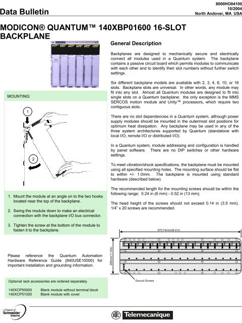
ata Bulletin8000HO041<strong>001</strong>0/2004North Andover, MA USAMODICON® QUANTUM 1<strong>40</strong>XBP01600 16-SLOTBACKPLANEGeneral DescriptionBackplanes are designed to mechanically secure and electricallyconnect all modules used in a Quantum system. The backplanecontains a passive circuit board which permits modules to communicatewith each other and to identify their slot numbers without further switchsettings.MOUNTING:1Six different backplane models are available with 2, 3, 4, 6, 10, or 16slots. Backplane slots are universal. In other words, any module mayfit into any slot. Almost all Quantum modules are designed to fit intosingle slots on a Quantum backplane; the only exception is the MMSSERCOS motion module and Unity processors, which require twocontiguous slots.There are no slot dependencies in a Quantum system, although powersupply modules should be mounted in the outermost slot positions foroptimum heat dissipation. Any backplane may be used in any of thethree system architectures supported by Quantum (standalone withlocal I/O, remote I/O or distributed I/O).21. Mount the module at an angle on to the two hookslocated near the top of the backplane.2. Swing the module down to make an electricalconnection with the backplane I/O bus connector.3. Tighten the screw at the bottom of the module tofasten it to the backplane.In a Quantum system, module addressing and configuration is handledby panel software. There are no DIP switches or other hardwaresettings.To meet vibration/shock specifications, the backplane must be mountedusing all specified mounting holes. The mounting surface should be flatto within +/- 1.0mm. The backplane is mounted using standardhardware (described below).The recommended length for the mounting screws should be within thefollowing range: 0.24 in (6 mm) - 0.52 in (13 mm).The head height of the screws should not exceed 0.14 in (3.5 mm).1/4” x 20 screws are recommended.670.74mm/26.41inPlease reference the Quantum AutomationHardware Reference Guide (8<strong>40</strong>USE10000) forimportant installation and grounding information.2<strong>90</strong>mm/11.42inOptional rack accessories are ordered separately.Ground Screws1<strong>40</strong>XCP500<strong>001</strong><strong>40</strong>XCP51000Blank module without terminal blockBlank module with cover