
You also want an ePaper? Increase the reach of your titles
YUMPU automatically turns print PDFs into web optimized ePapers that Google loves.
DOK-<strong>MTC200</strong>-NEW*FUN*V19-AW02-EN-P<br />
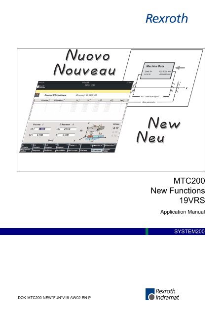
Machine Data<br />
Limit X+ 122.6000 mm<br />
Limit X- -56.0000 mm<br />
PLC interface signal<br />
Axis parameter<br />
<strong>MTC200</strong><br />
<strong>New</strong> <strong>Functions</strong><br />
<strong>19VRS</strong><br />
Application Manual<br />
X<br />
SYSTEM200
About this Documentation <strong>New</strong> <strong>Functions</strong> <strong>19VRS</strong><br />
Title<br />
Type of Documentation<br />
Document Typecode<br />
Internal File Reference<br />
Purpose of Documentation<br />
Record of Revisions<br />
Copyright<br />
Validity<br />
Published by<br />
Note<br />
<strong>MTC200</strong><br />
<strong>New</strong> <strong>Functions</strong><br />
<strong>19VRS</strong><br />
Application Manual<br />
DOK-<strong>MTC200</strong>-NEW*FUN*V19-AW02-EN-P<br />
• Box 1.1-19V-EN<br />
• Document number: 120-1700-B346-02/EN<br />
This documentation informs the user about the new functions in a new<br />
version. The new functions are introduced briefly.<br />
Description Release<br />
Date<br />
Notes<br />
120-1700-B346-01/EN 08.00 <strong>New</strong> issue for <strong>19VRS</strong><br />
120-1700-B346-02/EN 11.01 Chapter 1: Modification<br />
process<br />
© 2001 Rexroth Indramat GmbH<br />
Copying this document, giving it to others and the use or communication<br />
of the contents thereof without express authority, are forbidden. Offenders<br />
are liable for the payment of damages. All rights are reserved in the event<br />
of the grant of a patent or the registration of a utility model or design<br />
(DIN 34-1).<br />
The specified data is for product description purposes only and may not<br />
be deemed to be guaranteed unless expressly confirmed in the contract.<br />
All rights are reserved with respect to the content of this documentation<br />
and the availability of the product.<br />
Rexroth Indramat GmbH<br />
Bgm.-Dr.-Nebel-Str. 2 • D-97816 Lohr a. Main<br />
Telephone +49 (0)93 52/40-0 • Tx 68 94 21 • Fax +49 (0)93 52/40-48 85<br />
http://www.boschrexroth.de/<br />
Dept. BRC/ESM6 (EW/DH)<br />
This document has been printed on chlorine-free bleached paper..<br />
DOK-<strong>MTC200</strong>-NEW*FUN*V19-AW02-EN-P
<strong>New</strong> <strong>Functions</strong> <strong>19VRS</strong> Contents I<br />
Contents<br />
1 Modification Process 1-1<br />
1.1 General........................................................................................................................................... 1-1<br />
1.2 DOK-<strong>MTC200</strong>-NEW*FUN*V19-AW02-EN-P ................................................................................. 1-1<br />
Chapter 6.4 „Spindle RPM limitation“ ...................................................................................... 1-1<br />
Chapter 6.5 „Feed Limitation“ .................................................................................................. 1-1<br />
2 General Information 2-1<br />
2.1 Purpose of this documentation ...................................................................................................... 2-1<br />
2.2 Deadlines ....................................................................................................................................... 2-1<br />
2.3 Hardware requirements.................................................................................................................. 2-1<br />
User interface........................................................................................................................... 2-1<br />
Firmware .................................................................................................................................. 2-2<br />
2.4 Software requirements ................................................................................................................... 2-2<br />
Software options ...................................................................................................................... 2-3<br />
3 Discontinuation of features 3-1<br />
3.1 MTC02 / MTC03............................................................................................................................. 3-1<br />
3.2 Operating and visualizing terminal SOT ........................................................................................ 3-1<br />
3.3 Analog axes ................................................................................................................................... 3-1<br />
4 Hardware components 4-1<br />
4.1 Higher memory capacity for MTS-P and MTS-R ........................................................................... 4-1<br />
4.2 BT bus connection for BTV20.3 ..................................................................................................... 4-2<br />
5 Software components 5-1<br />
5.1 Graphical User Interface GUI......................................................................................................... 5-1<br />
5.2 Standardized user interface WinHMI ............................................................................................. 5-1<br />
5.3 SWD-<strong>MTC200</strong>-004-<strong>19VRS</strong>-NN-C1.44........................................................................................... 5-1<br />
6 General functions 6-1<br />
6.1 WinHMI .......................................................................................................................................... 6-1<br />
Error texts for small operating devices .................................................................................... 6-1<br />
Displaying and processing online data .................................................................................... 6-1<br />
6.2 Data backup Backup/Restore ........................................................................................................ 6-2<br />
Procedure................................................................................................................................. 6-3<br />
Preparation............................................................................................................................... 6-3<br />
Saving (backup) ....................................................................................................................... 6-4<br />
Restore..................................................................................................................................... 6-5<br />
DOK-<strong>MTC200</strong>-NEW*FUN*V19-AW02-EN-P
II Contents <strong>New</strong> <strong>Functions</strong> <strong>19VRS</strong><br />
Restore data in the control....................................................................................................... 6-5<br />
6.3 Intelligent security technology IST ................................................................................................. 6-6<br />
Rexroth Indramat CNC control and drive system with integrated intelligent security<br />
technology IST ......................................................................................................................... 6-6<br />
Comparison with conventional security technology................................................................. 6-7<br />
Overview of safety functions for personal protection............................................................... 6-8<br />
Design of the intelligent security technology............................................................................ 6-8<br />
Additional documentation......................................................................................................... 6-8<br />
6.4 Upper spindle speed limit............................................................................................................... 6-9<br />
6.5 Feed limit...................................................................................................................................... 6-11<br />
6.6 Travel range limits........................................................................................................................ 6-12<br />
6.7 Quick stop upon probe detection ................................................................................................. 6-14<br />
7 CNC functions 7-1<br />
7.1 Feed to positive stop ...................................................................................................................... 7-1<br />
7.2 Enhanced NC syntax (NC control structures)................................................................................ 7-2<br />
Overview .................................................................................................................................. 7-2<br />
Conditions in control structures................................................................................................7-3<br />
Block instructions ..................................................................................................................... 7-4<br />
IF instruction............................................................................................................................. 7-4<br />
FOR instruction ........................................................................................................................ 7-5<br />
WHILE instruction .................................................................................................................... 7-5<br />
REPEAT UNTIL instruction...................................................................................................... 7-5<br />
CONTINUE instruction............................................................................................................. 7-6<br />
BREAK instruction ................................................................................................................... 7-6<br />
SWITCH instruction ................................................................................................................. 7-7<br />
Indexable NC variables............................................................................................................ 7-7<br />
7.3 Adaptive feed control (G26) ........................................................................................................... 7-8<br />
Boundary conditions ................................................................................................................ 7-8<br />
Syntax ...................................................................................................................................... 7-8<br />
Parameters .............................................................................................................................. 7-9<br />
Machine parameters ................................................................................................................ 7-9<br />
PLC interface signals ............................................................................................................... 7-9<br />
Problem of „inclined axis“....................................................................................................... 7-11<br />
Parameterization.................................................................................................................... 7-11<br />
Additional documentation....................................................................................................... 7-12<br />
7.4 Switchover to second encoder system (Adaptive Depth) ............................................................ 7-12<br />
Application.............................................................................................................................. 7-12<br />
<strong>New</strong> axis parameters .............................................................................................................7-12<br />
G codes for switchover to second encoder system ............................................................... 7-12<br />
7.5 Test mode .................................................................................................................................... 7-13<br />
Purpose.................................................................................................................................. 7-13<br />
Suppressing the help function output .................................................................................... 7-13<br />
Locking axes and spindles..................................................................................................... 7-13<br />
Test feed ................................................................................................................................ 7-15<br />
Rapid program execution....................................................................................................... 7-16<br />
Online simulation ................................................................................................................... 7-16<br />
DOK-<strong>MTC200</strong>-NEW*FUN*V19-AW02-EN-P
<strong>New</strong> <strong>Functions</strong> <strong>19VRS</strong> Contents III<br />
Suppressing tool transfer and tool movements ..................................................................... 7-16<br />
8 PLC functions 8-1<br />
8.1 Switching from PEA external to PEA internal ................................................................................ 8-1<br />
8.2 BT bus as I/O page ........................................................................................................................ 8-3<br />
8.3 Parameters for setting the data consistency at the Interbus.......................................................... 8-4<br />
8.4 Control of the Interbus system (IBM2, G4) ....................................................................................8-5<br />
8.5 Possible faults during the start-up of IBS G4 and their elimination................................................ 8-6<br />
9 Tool management functions 9-1<br />
9.1 Flexible equipment check .............................................................................................................. 9-1<br />
No equipment check upon reverse start .................................................................................. 9-1<br />
9.2 Movement indication PLC turret..................................................................................................... 9-1<br />
9.3 Modifications .................................................................................................................................. 9-1<br />
Remaining tool life ................................................................................................................... 9-1<br />
10 Parameters/interface signals 10-1<br />
10.1 Maintaining the reference system upon control reset .................................................................. 10-1<br />
10.2 Axis transfer for all processes possible........................................................................................ 10-1<br />
10.3 <strong>New</strong> interface signals ................................................................................................................... 10-2<br />
AxxS.HOLD............................................................................................................................ 10-2<br />
PxxS.RVACT ......................................................................................................................... 10-2<br />
10.4 Modifications ................................................................................................................................ 10-2<br />
Increasing the path velocity ................................................................................................... 10-2<br />
11 List of Figures 11-1<br />
12 Index 12-1<br />
13 Service & Support 13-1<br />
13.1 Helpdesk ...................................................................................................................................... 13-1<br />
13.2 Service-Hotline............................................................................................................................. 13-1<br />
13.3 Internet ......................................................................................................................................... 13-1<br />
13.4 Vor der Kontaktaufnahme... - Before contacting us..................................................................... 13-1<br />
13.5 Kundenbetreuungsstellen - Sales & Service Facilities ................................................................ 13-2<br />
14 Revisions to this Document 14-1<br />
DOK-<strong>MTC200</strong>-NEW*FUN*V19-AW02-EN-P
IV Contents <strong>New</strong> <strong>Functions</strong> <strong>19VRS</strong><br />
DOK-<strong>MTC200</strong>-NEW*FUN*V19-AW02-EN-P
<strong>New</strong> <strong>Functions</strong> <strong>19VRS</strong> Modification Process 1-1<br />
1 Modification Process<br />
1.1 General<br />
DOK-<strong>MTC200</strong>-NEW*FUN*V19-AW02-EN-P<br />
Compared with the previous version, all modifications of documentation<br />
are described in this chapter. A modified documentation is visible through<br />
increasing the index in type code, e.g. AW01 → AW02.<br />
1.2 DOK-<strong>MTC200</strong>-NEW*FUN*V19-AW02-EN-P<br />
Chapter 6.4 „Spindle RPM limitation“<br />
Chapter 6.5 „Feed Limitation“<br />
Section „boundary conditions“<br />
Incorrect: "With each change of the limits, the PLC status signal is set to<br />
‘0’ for a PLC cycle. "<br />
Correction: The above block was deleted without substitution.<br />
Section „boundary conditions“<br />
Incorrect: "With each change of the limits, the PLC status signal is set to<br />
‘0’ for a PLC cycle. "<br />
Correction: The above block was deleted without substitution.
1-2 Modification Process <strong>New</strong> <strong>Functions</strong> <strong>19VRS</strong><br />
DOK-<strong>MTC200</strong>-NEW*FUN*V19-AW02-EN-P
<strong>New</strong> <strong>Functions</strong> <strong>19VRS</strong> General Information 2-1<br />
2 General Information<br />
2.1 Purpose of this documentation<br />
2.2 Deadlines<br />
2.3 Hardware requirements<br />
User interface<br />
DOK-<strong>MTC200</strong>-NEW*FUN*V19-AW02-EN-P<br />
In Version <strong>19VRS</strong>, existing functions were enhanced and new functions<br />
added. <strong>New</strong> hardware components are also available. This document<br />
describes the modifications and gives a short overview of the new<br />
software and hardware components.<br />
Note: More information about the new components can be found in<br />
the updated individual documents.<br />
Software version <strong>19VRS</strong> has been released since June 2000 and can be<br />
ordered.<br />
The availability of the hardware components mentioned in this document<br />
can differ from this deadline. Please note the specifications for the<br />
corresponding product!<br />
The user interface of the software and firmware version <strong>19VRS</strong> for<br />
<strong>MTC200</strong> can be installed on the Rexroth Indramat BTV20 and BTV30<br />
operator panels and on most standard IBM compatible PCs.<br />
Depending on the employed operating system, the following hardware<br />
prerequisites are expected:<br />
MS-DOS Windows-NT<br />
Processor type ≥ 5x86 / 133 MHz ≥ Pentium P166<br />
Memory ≥ 32 MB ≥ 64 MB<br />
Display VGA Color 640*480,<br />
minimum 256 colors<br />
65535 colors<br />
Hard disk ≥ 100 MB free space ≥ 250 MB free space<br />
Floppy disk drive<br />
(optional CD-ROM)<br />
for installation and data backup<br />
for installation<br />
Serial interface RS232C or RS485 for connection to <strong>MTC200</strong>-R<br />
Parallel interface Printer connection<br />
Fig. 2-1: Hardware requirements<br />
There must be at least 2 free ISA bus slots available if the MTC-P and<br />
MTS-P controller components are to be included in the PC.<br />
Depending on the required option, further hardware components (such as<br />
interface cards) will be necessary.
2-2 General Information <strong>New</strong> <strong>Functions</strong> <strong>19VRS</strong><br />
Firmware<br />
2.4 Software requirements<br />
Note: Due to the required computing power and free memory space,<br />
the Windows NT version of the <strong>19VRS</strong> software can no<br />
longer be used in the BTV01. There will only be the DOS<br />
version that can be used in the BTV01 under the <strong>19VRS</strong><br />
software.<br />
The firmware of version 19 can be used on the following hardware<br />
platforms:<br />
Hardware type Firmware type<br />
MTC-P01.2-xxx FWA-MTCP01-M01-<strong>19VRS</strong>-NN<br />
MTC-R01.1-xxx<br />
FWA-MTCR0*-M01-<strong>19VRS</strong>-NN<br />
MTC-R02.1-xxx<br />
FWA-MTCR0*-M01-<strong>19VRS</strong>-NN<br />
MTS-P01.2-xx-xxx<br />
FWA-MTSP01-S01-<strong>19VRS</strong>-NN<br />
FWA-MTSP01-M01-<strong>19VRS</strong>-NN<br />
MTS-P02.2-xx-xxx<br />
FWA-MTSP02-S01-<strong>19VRS</strong>-NN<br />
FWA-MTSP02-M01-<strong>19VRS</strong>-NN<br />
MTS-R01.2-M1-xxx<br />
FWA-MTSR0*-M01-<strong>19VRS</strong>-NN<br />
FWA-MTSR0*-S01-<strong>19VRS</strong>-NN<br />
MTS-R02.2-M1-xxx<br />
FWA-MTSR0*-M01-<strong>19VRS</strong>-NN<br />
FWA-MTSR0*-S01-<strong>19VRS</strong>-NN<br />
Fig. 2-2: Supported hardware types<br />
Version 19 does not support the hardware types of the MT-CNC!<br />
The user interface of the <strong>19VRS</strong> software and firmware version for<br />
<strong>MTC200</strong> can be used under the operating systems MS-DOS (version<br />
6.22) and Windows NT 4.0.<br />
For operating system Windows NT 4.0, service pack 5 is required.<br />
The installation program checks whether the required service pack has<br />
been installed!<br />
Note: The corresponding service pack must be activated again if<br />
additional operating system components (such as a network<br />
driver) are installed subsequently!<br />
Rexroth Indramat supplies version <strong>19VRS</strong> only in conjunction with MS-<br />
DOS 6.22 or Windows-NT 4.0.<br />
Some functions of Version 19 are only available under Windows NT 4.0.<br />
DOK-<strong>MTC200</strong>-NEW*FUN*V19-AW02-EN-P
<strong>New</strong> <strong>Functions</strong> <strong>19VRS</strong> General Information 2-3<br />
Software options<br />
DOK-<strong>MTC200</strong>-NEW*FUN*V19-AW02-EN-P<br />
Within software version 19, the functions listed in the following table will<br />
only be available as an option.<br />
The required function must be ordered by its type designation and must<br />
be installed using the enabling code that is included in the delivery.<br />
Function Type<br />
Custom Display System - CDS - configuration and<br />
runtime version<br />
SWS-MT*BVS-PRO-18VRS-MS<br />
Custom Display System – CDS<br />
- runtime version only<br />
SWS-MT*BVS-RUN-18VRS-MS<br />
Graphical NC Editor - GNE SWS-<strong>MTC200</strong>-GNE-18VRS-MS<br />
Online NC simulation for MS-DOS - SIM SWS-<strong>MTC200</strong>-SIM-17VRS-MS-MS*DOS<br />
Online and offline NC simulation{ for WindowsNT - SIM SWS-<strong>MTC200</strong>-SIM-17VRS-MS-WIN*NT<br />
NC User Compiler - NUC SWS-<strong>MTC200</strong>-NUC-17VRS-MS<br />
Multi Control Interface - MCI SWS-<strong>MTC200</strong>-MCI-18VRS-MS-WIN*NT<br />
SFC Sequence Modes and Diagnosis SWS-<strong>MTC200</strong>-SKT-<strong>19VRS</strong>-MS<br />
Fast Measurement - SME SWS-<strong>MTC200</strong>-SME-18VRS-MS<br />
Drill Breakage Monitoring - BBU SWS-<strong>MTC200</strong>-BBU-18VRS-MS<br />
Fig. 2-3: Software options<br />
This document also contains brief descriptions of these new functions that<br />
are only available as options.
2-4 General Information <strong>New</strong> <strong>Functions</strong> <strong>19VRS</strong><br />
DOK-<strong>MTC200</strong>-NEW*FUN*V19-AW02-EN-P
<strong>New</strong> <strong>Functions</strong> <strong>19VRS</strong> Discontinuation of features 3-1<br />
3 Discontinuation of features<br />
3.1 MTC02 / MTC03<br />
DOK-<strong>MTC200</strong>-NEW*FUN*V19-AW02-EN-P<br />
Version 19 does no longer support the types MTC02 and MTC03 of the<br />
controller product family MT-CNC.<br />
3.2 Operating and visualizing terminal SOT<br />
3.3 Analog axes<br />
Version 19 does no longer support the operating and visualizing terminal<br />
SOT02. The functionality is replaced by the BTV05, BTV06 and the<br />
BTC06.<br />
Analog axes are no longer supported due to the discontinuation of MTC02<br />
and MTC03.
3-2 Discontinuation of features <strong>New</strong> <strong>Functions</strong> <strong>19VRS</strong><br />
DOK-<strong>MTC200</strong>-NEW*FUN*V19-AW02-EN-P
<strong>New</strong> <strong>Functions</strong> <strong>19VRS</strong> Hardware components 4-1<br />
4 Hardware components<br />
DOK-<strong>MTC200</strong>-NEW*FUN*V19-AW02-EN-P<br />
<strong>New</strong> hardware components are available or are being prepared for the<br />
<strong>MTC200</strong> controller product family. Software version <strong>19VRS</strong> is required to<br />
support these components.<br />
4.1 Higher memory capacity for MTS-P and MTS-R<br />
As standard, the PLC modules in ISA bus plug-in card format (MTS-P)<br />
and in RECO format (MTC-S) are now equipped with a 2 MB-RAM<br />
memory.<br />
The RAM memory size is defined as follows in the type code of the<br />
modules:<br />
1. PLC module in ISA bus plug-in card format<br />
MTS-P0x.2-D2-...<br />
2. PLC module in RECO format<br />
MTS-R0x.2-M2-...<br />
2 = 2 MB RAM memory<br />
2 = 2 MB RAM memory
4-2 Hardware components <strong>New</strong> <strong>Functions</strong> <strong>19VRS</strong><br />
4.2 BT bus connection for BTV20.3<br />
The BT bus can be used to connect up to four operator panels of type<br />
BTM15/16 or BTA20. The maximum length of the BT bus may be up to 50<br />
m (from the connection point to the last user). This applies to the<br />
connection of only one device and the permissible maximum number of 4<br />
devices. It is not possible to directly access the I/O data of the operator<br />
panels from the PLC (e.g. %IBP*.*). Data is exclusively exchanged via the<br />
core image storage.<br />
The address assignments required for programming can be found in the<br />
corresponding documents of the devices to be connected.<br />
Indramat<br />
OPERATOR PROGRAMMER<br />
BTV20/30<br />
MTS-P<br />
X15<br />
IKS 0056 BT bus<br />
IKS 0056<br />
BT bus<br />
Up to 2 further<br />
operator terminals<br />
in BT bus<br />
Fig. 4-1: BT bus overview<br />
TEMP HD POWER<br />
E-STOP<br />
Indramat<br />
MASCHINE<br />
EIN<br />
MASCHINE<br />
AUS<br />
BTA20<br />
BETRIEBSART<br />
AUTO<br />
START<br />
LOCAL<br />
MACHINE CONTROL<br />
BTM16<br />
10 20 30 40<br />
8 50<br />
6<br />
60<br />
4<br />
70<br />
2<br />
80<br />
1<br />
100<br />
0<br />
120<br />
%<br />
75 80 85 90<br />
70 95<br />
65<br />
100<br />
60<br />
105<br />
55<br />
110<br />
50<br />
115<br />
45<br />
120<br />
%<br />
10<br />
20 30<br />
40 F<br />
8 50<br />
6<br />
60<br />
4<br />
70<br />
2<br />
80<br />
1<br />
100<br />
0<br />
120<br />
ZUSTIMM-<br />
TASTER<br />
ANSCHLUß<br />
HANDBEDIEN-<br />
GERÄT<br />
DOK-<strong>MTC200</strong>-NEW*FUN*V19-AW02-EN-P<br />
%<br />
80<br />
-<br />
90<br />
0<br />
10<br />
20<br />
70<br />
30<br />
60<br />
40<br />
50<br />
BT-Bus_Uebers-en.FH7<br />
+
<strong>New</strong> <strong>Functions</strong> <strong>19VRS</strong> Software components 5-1<br />
5 Software components<br />
5.1 Graphical User Interface GUI<br />
DOK-<strong>MTC200</strong>-NEW*FUN*V19-AW02-EN-P<br />
This software component is the enhancement of version 18 of the<br />
graphical user interface GUI.<br />
The user interface of the <strong>19VRS</strong> software version runs under the<br />
operating systems MS-DOS and WindowsNT. Some GUI functions,<br />
however, only run under WindowsNT.<br />
Version 19 of the GUI can be used for the controller family <strong>MTC200</strong>.<br />
Version 19 does no longer support the controller family MT-CNC.<br />
The GUI for the control system <strong>MTC200</strong> is available in 2 versions:<br />
Description Type<br />
<strong>MTC200</strong> / MS-DOS SWA-<strong>MTC200</strong>-GBO-<strong>19VRS</strong>-MS-CD*FD-MS*DOS<br />
<strong>MTC200</strong> / WindowsNT SWA-<strong>MTC200</strong>-GBO-<strong>19VRS</strong>-MS-CD*FD-WIN*NT<br />
Fig. 5-1: User interface versions<br />
GUI version 19 requires firmware version 19 in the controller kernel.<br />
5.2 Standardized user interface WinHMI<br />
The user interface is based on the Microsoft Windows NT 4.0 operating<br />
system and on the <strong>MTC200</strong> software environment of Rexroth Indramat.<br />
Version 19 is based on software version 18.<br />
Description Type<br />
<strong>MTC200</strong> / WindowsNT SWA-<strong>MTC200</strong>-HMI-<strong>19VRS</strong>-MS-CD*FD<br />
5.3 SWD-<strong>MTC200</strong>-004-<strong>19VRS</strong>-NN-C1.44<br />
This firmware includes the new CNC and PLC functions of the<br />
<strong>MTC200</strong>controller family.<br />
The firmware is loaded into flash memories via the PC.<br />
Upon delivery, the firmware is installed according to the order<br />
specifications. In the event of a necessary update, the firmware can be<br />
reloaded via the GUI user interface.<br />
The latest firmware on diskette is part of the delivery of the user interface<br />
SWA.
5-2 Software components <strong>New</strong> <strong>Functions</strong> <strong>19VRS</strong><br />
DOK-<strong>MTC200</strong>-NEW*FUN*V19-AW02-EN-P
<strong>New</strong> <strong>Functions</strong> <strong>19VRS</strong> General functions 6-1<br />
6 General functions<br />
6.1 WinHMI<br />
Error texts for small operating devices<br />
Displaying and processing online data<br />
DOK-<strong>MTC200</strong>-NEW*FUN*V19-AW02-EN-P<br />
Version 19 supports the visualization of the small operating devices<br />
BTV05, BTV06 and BTC06. The NC block number display and process<br />
error texts are shown. The error texts for the small operating devices<br />
BTV05, BTV06 and BTC06 are loaded into the CNC memory. The small<br />
operating devices BTV05, BTV06 and BTC06 read these texts of the CNC<br />
memory for diagnosis purposes.<br />
This function is available by pressing OP7 "Maintenance" and F8<br />
"Download error text".<br />
Version 19 allows to display or edit online data of NC variables, NC<br />
events and D corrections. The data display is dynamic, i. e. if a value is<br />
modified via the PLC and/or NC program, the value is automatically<br />
updated.<br />
This function is available by pressing OP8 "Control" and F6 "Further<br />
functions".<br />
The data for each component is shown in a table. Lines can be inserted,<br />
deleted and edited by means of the F keys. The following figure shows,<br />
for example, the D correction table.<br />
Fig. 6-1: Display and edit D corrections<br />
D-korr_wert.BMP
6-2 General functions <strong>New</strong> <strong>Functions</strong> <strong>19VRS</strong><br />
6.2 Data backup Backup/Restore<br />
EDP systems are no static systems. Data is created, modified, moved or<br />
deleted permanently. Components are added or removed, updates are<br />
executed, settings are modified. Furthermore, user data and system data<br />
exist. The Rexroth Indramat programs "Backup" and "Restore" are<br />
available for the backup and restore of these data and settings.<br />
User data is saved on the local hard disk or an external data storage<br />
medium (server, MO, diskettes) by the data backup program. After a<br />
system crash it will be possible to restore the data.<br />
User data<br />
MO-Drive<br />
BTV Hard disk, diskette or MO drive<br />
Fig. 6-2: Backup and restore user data<br />
backup<br />
restore<br />
AnwSich-en.FH7<br />
DOK-<strong>MTC200</strong>-NEW*FUN*V19-AW02-EN-P
<strong>New</strong> <strong>Functions</strong> <strong>19VRS</strong> General functions 6-3<br />
Procedure<br />
Preparation<br />
DOK-<strong>MTC200</strong>-NEW*FUN*V19-AW02-EN-P<br />
By means of an archive program, data files on the hard disk are saved<br />
and can be restored if necessary. During archiving, the files are<br />
compressed and copied to the data storage medium. For archiving<br />
diskettes, hard disks or MO drives can be used as data storage mediums.<br />
Production<br />
Preparation<br />
Backup<br />
Drives<br />
NC PLC<br />
Save Load<br />
Backup<br />
User data<br />
Restore<br />
Disk, MO, portable PC,<br />
network drive, ...<br />
Fig. 6-3: Archiving procedure<br />
Devices/<br />
control<br />
PC<br />
hard disk<br />
External<br />
storage<br />
Verfahr-en.FH7<br />
Before carrying out a backup, the data modified within the control (NC<br />
variables, NC events, D corrections, tool lists, zero offset data, machine<br />
data, remanent PLC data) must be saved on the hard disk. The SERCOS<br />
parameters have to be saved, too. For this, the corresponding menus are<br />
available or the archive function in the GUI can be used. The remanent<br />
PLC data must be saved with the block commands in the PLC.
6-4 General functions <strong>New</strong> <strong>Functions</strong> <strong>19VRS</strong><br />
Saving (backup)<br />
The backup is carried out in two steps. The data to be saved is indicated<br />
in a batch file. First, all data to be saved is copied to a temporary directory<br />
on the local hard disk. In addition to the temporary directory, the structure<br />
file "archive.asl" is created. This structure file includes all necessary<br />
information about the saved data (e. g. origin, date etc.). The files are not<br />
compressed unless all files to be saved are available. The complete<br />
content of the temporary directory is always compressed. The result is a<br />
ZIP file. A ZIP file which exceeds the size of the storage medium selected<br />
will be divided automatically among multiple data storage mediums.<br />
When the compressing is completed, the temporary directory and all subdirectories<br />
are deleted.<br />
Temp.<br />
directories<br />
Fig. 6-4: User data backup procedure<br />
Batch<br />
file<br />
Create temporary directories<br />
and files<br />
Compress<br />
ZIP file<br />
Structure<br />
file<br />
Abl-Back-en.FH7<br />
DOK-<strong>MTC200</strong>-NEW*FUN*V19-AW02-EN-P
<strong>New</strong> <strong>Functions</strong> <strong>19VRS</strong> General functions 6-5<br />
Restore<br />
Restore data in the control<br />
DOK-<strong>MTC200</strong>-NEW*FUN*V19-AW02-EN-P<br />
Starting with the selected archive file (ZIP file) the files are decompressed<br />
in a temporary directory. The complete content of the archive file is<br />
always decompressed. Single files cannot be restored. If all files are<br />
decompressed without errors, the files are copied to the destination<br />
directories. If the files have been copied successfully, the temporary<br />
directory will be deleted.<br />
Temp.<br />
directories<br />
Fig. 6-5: User data restoring procedure<br />
ZIP file<br />
Decompress in temporary<br />
directories<br />
Copy to destination<br />
directories<br />
Destination<br />
directories<br />
Structure<br />
file<br />
Abl-Rest-en.FH7<br />
After the restore, the changeable data (NC variables, NC events, D<br />
corrections, tool lists, zero offset data, machine data, remanent PLC data)<br />
must be restored in the control. For this, the corresponding menus are<br />
available or the archive function in the GUI can be used. The remanent<br />
PLC data is restored with the block commands in the PLC.
6-6 General functions <strong>New</strong> <strong>Functions</strong> <strong>19VRS</strong><br />
6.3 Intelligent security technology IST<br />
Rexroth Indramat CNC control and drive system with integrated<br />
intelligent security technology IST<br />
RECO12<br />
Interbus<br />
<strong>MTC200</strong> controller family<br />
Safety<br />
I/O module<br />
SYSTEM200<br />
<strong>MTC200</strong> controller family<br />
BTV20<br />
BTA20<br />
SERCOS<br />
interface<br />
DIAX04 drive family<br />
DIAX04<br />
Fig. 6-6: SYSTEM200 with intelligent security technology<br />
Machine<br />
Uebersicht-en.FH7<br />
The Rexroth Indramat control and drive system SYSTEM200 with<br />
intelligent security technology basically consists of components of the<br />
<strong>MTC200</strong> controller family and DIAX04 drive family.<br />
The intelligent security technology is realized by hardware and software<br />
components providing the safety functions.<br />
For using IST, an additional hardware component is required for each<br />
axis. The RMP safety I/O module based on the RECO12 I/O modules<br />
provides mechanically separated safety inputs and potential-free safety<br />
outputs.<br />
All other components of the intelligent security technology are software<br />
components. These consist of <strong>MTC200</strong> and DIAX04 firmware parts and<br />
PLC user program parts.<br />
A detailed component list for the intelligent security technology is included<br />
in the IST application manual. It is available under the order number<br />
DOK-CONTRL-IST********-AW01-EN-P<br />
The control system <strong>MTC200</strong> consists of an industrial PC BTV20 or<br />
BTV30 equipped with the CNC module MTC-P and the PLC module MTS-<br />
P (ISA bus plug-in cards).<br />
The RECO versions MTC-R and MTS-R can also be used for the<br />
intelligent security technology IST.<br />
The CNC module contains a CNC processor with integrated axis<br />
processor and up to 3 additional PC104 axis processors. Each axis<br />
processor allows to control up to 8 digital drives via a SERCOS fibre optic<br />
loop.<br />
The selection and status signals of the intelligent security technology must<br />
be processed in two channels in the complete system. The RMP safety<br />
I/O module based on RECO12 is available for the communication<br />
between the I/O level and the drive.<br />
DOK-<strong>MTC200</strong>-NEW*FUN*V19-AW02-EN-P
<strong>New</strong> <strong>Functions</strong> <strong>19VRS</strong> General functions 6-7<br />
DIAX04 drive family<br />
DOK-<strong>MTC200</strong>-NEW*FUN*V19-AW02-EN-P<br />
The DIAX 04 drive system consists of a HVE or HVR power supply unit<br />
connected directly to the power supply system and several connected<br />
drives.<br />
Each drive is equipped with a HDS or HDD drive controller and one of the<br />
following motor types:<br />
• MKD or MHD synchronous motor or<br />
• 2AD asynchronous motor or<br />
• 1MB built-in asynchronous motor or<br />
• LSF, LAF or LAR built-in linear motor.<br />
The drive controllers are connected to the axis processors of the CNC<br />
module by a SERCOS fibre optic loop.<br />
Comparison with conventional security technology<br />
The difference between a control and drive system with intelligent security<br />
technology and systems with conventional, discrete security technology is<br />
that in the intelligent drives the safety functions are integrated directly and<br />
the control is integrated as hardware and software.<br />
This allows to achieve an increased functionality at maximum security in<br />
all operating modes.<br />
The intelligent security technology is primarily not intended for replacing<br />
conventional security technology components, such as emergency off,<br />
switchgears and protection door controls. However, the following<br />
conventional security technology components may not be required:<br />
• Motor zero-speed relay<br />
• Speed monitor<br />
• Power contactors between controllers and motors<br />
• Limit switch or position cams for area detection<br />
At the same time, the available personnel and machine safety is<br />
increased since the functionality and the global reaction of the system<br />
compared to similar systems with conventional security technology has<br />
been considerably improved.<br />
The safety signal transmission takes place via the standard field buses<br />
Interbus and the SERCOS interface.<br />
This leads to a considerably easier wiring structure within the machine.<br />
Special control module and drive controller versions are not required for<br />
the use of the intelligent security technology IST.
6-8 General functions <strong>New</strong> <strong>Functions</strong> <strong>19VRS</strong><br />
Overview of safety functions for personal protection<br />
Safe stop<br />
Safe stop of the machine<br />
Safely reduced speed<br />
Safely limited absolute position<br />
Safe cams<br />
Design of the intelligent security technology<br />
Additional documentation<br />
Based on the realized monitoring, the intelligent security technology IST<br />
provides the following functions:<br />
The safe stop protects the axis against unintentional start. In case of a<br />
safe stop, the power supply to the drive system is interrupted.<br />
Like the safe stop, the safe stop of the machine also protects the axis<br />
against unintentional start. The drive system is stopped at a natural point<br />
in the production process (stop of the machine). All control functions<br />
between the electronic control and the drive motor are maintained. Safety<br />
measures prevent the drive from executing dangerous movements in<br />
case of errors.<br />
Safety measures in the CNC control and drive system prevent the drive<br />
(axis or spindle) from exceeding the specified speed limit.<br />
Safety measures in the CNC control and drive system prevent the axis<br />
from moving out of the admissible travel range.<br />
The safe cams allow a safe division of the axis travel range. They can be<br />
used for switching between various safety functions or the safe release of<br />
external safety mechanisms.<br />
The intelligent security technology is designed according to DIN EN<br />
60954-1 "Safety-related control parts", part 3, under consideration of the<br />
DKE (German commission of electrics) work paper 226.03 "Safetyrelevant<br />
functions of electric drive systems in machines".<br />
A detailed description of the intelligent security technology is available<br />
under the order number<br />
DOK-CONTRL-IST********-AW01-EN-P<br />
DOK-<strong>MTC200</strong>-NEW*FUN*V19-AW02-EN-P
<strong>New</strong> <strong>Functions</strong> <strong>19VRS</strong> General functions 6-9<br />
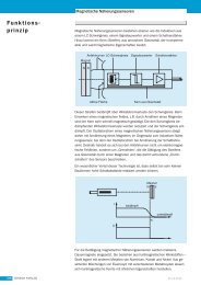
6.4 Upper spindle speed limit<br />
Machine data<br />
PLC interface signal<br />
Boundary conditions<br />
DOK-<strong>MTC200</strong>-NEW*FUN*V19-AW02-EN-P<br />
In addition to the max. spindle speed for main spindle operation defined in<br />
the axis parameter ‘Cxx.049’, it is now possible to limit the max. spindle<br />
speed during machine operation by means of further variables.<br />
|n|<br />
Max. machine-specific speed (parameter)<br />
Max. safety-related speed (PLC)<br />
Max. programmable speed (CNC)<br />
Max. speed for constant cutting speed (G92)<br />
max_spindeldreh-en.FH7<br />
Fig. 6-7: Upper spindle speed limits<br />
The max. safety-related speed (PLC) and the max. programmable speed<br />
(CNC) are set for each axis in machine data page 2.<br />
STRUCT 2 Upper spindle speed limit<br />
Safety-related speed limit active BOOL NoNC,NoSPS,NoGUI,NoPwGUI<br />
Max. safety-related speed (PLC) SPEED NoNC,SPS,NoGUI,NoPwGUI<br />
Max. technol. speed (CNC)<br />
END_STRUCT<br />
ARRAY [<br />
SPEED NC,SPS,GUI,PwGUI<br />
Axis no. SP_AXIS 1..12<br />
] OF STRUCT<br />
• AxxC.SPEED The axis control signal is used to activate the<br />
safety-related speed limit.<br />
• AxxS.SPEED The axis status signal is set as soon as the speed<br />
limit is active.<br />
• The set-up man can modify the programmable speed limit within the<br />
machine data only by entering a special password and if the NC does<br />
not execute an NC program at the same time.<br />
• The speed limits can be modified at any time in the PLC by means of<br />
MTD_WR.<br />
• The speed limit can be programmed for all spindles of a process within<br />
an NC block by means of MTD_commands.<br />
• The PLC can switch the speed limit monitoring on and off by means of<br />
the axis-specific control signal ‘AxxC.SPEED’.<br />
• The user can recognize the effectiveness of the speed limits in the<br />
machine data by means of the data element ‘Safety-related speed limit<br />
active’ and the control signal ‘AxxC.SPEED’.<br />
• The NC monitors the spindle speed limits in spindle speed mode only<br />
if control signal ‘AxxC.SPEED’ is set. Speed limit modifications as well<br />
as activation and deactivation of the monitoring are immediately<br />
integrated by the NC.
6-10 General functions <strong>New</strong> <strong>Functions</strong> <strong>19VRS</strong><br />
• When switching on the main spindle synchronization, the NC<br />
determines the max. admissible speed of the leading spindle on the<br />
basis of all transmission ratios and speed limits. Every time when<br />
modifying the speed limit of the leading or synchronous spindles or<br />
when activating or deactivating the safety-related speed limit, the NC<br />
recalculates the maximum speed of the leading spindle. The NC<br />
carries out any possibly required limitation synchronously for all<br />
spindles involved in the synchronization.<br />
• If the actual spindle speed exceeds the speed limit when switching on<br />
the interface signal ´Activate limit´, the NC reduces the speed of the<br />
concerned spindle to the smallest maximum limit speed by considering<br />
the other speed limits.<br />
• If a coupling (G33, G63, G64, G65, G95) or main spindle<br />
synchronization is active when switching on, the NC adjusts the<br />
spindle speed and the path velocity of the feed axes or spindles<br />
involved in the coupling or synchronization.<br />
• Modifications of the nominal speed value carried out by means of the<br />
spindle override are ignored.<br />
• In case of PLC-controlled spindles, the limited speed has to be read at<br />
each positive edge of this status signal and transferred to the external<br />
spindle.<br />
Safety-related speed limit<br />
The safety-related speed limit allows the machine manufacturer to limit<br />
the spindle speed when using a new chuck or opening the protective<br />
door.<br />
Programmable speed limit<br />
The programmable speed limit allows the NC programmer to limit the<br />
admissible spindle speed under consideration of the technological<br />
aspects.<br />
DOK-<strong>MTC200</strong>-NEW*FUN*V19-AW02-EN-P
<strong>New</strong> <strong>Functions</strong> <strong>19VRS</strong> General functions 6-11<br />
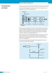
6.5 Feed limit<br />
Machine data<br />
PLC interface signal<br />
Boundary conditions<br />
DOK-<strong>MTC200</strong>-NEW*FUN*V19-AW02-EN-P<br />
In addition to the max. axis speed defined in axis parameter ‘Cxx.016’, it<br />
is now possible to limit the axis speed during machine operation by<br />
means of a further variable.<br />
|v|<br />
Fig. 6-8: Axis speed limits<br />
Max. axis speed (parameter)<br />
Safety-relevant axis speed<br />
max_achsgeschw-en.FH7<br />
The safety-related axis speed allows the machine manufacturer to reduce<br />
the maximum admissible axis speed (and thus the path velocity) for<br />
machining a heavy workpiece or opening the protective door.<br />
The safety-related axis speed is set for each axis in machine data page<br />
11.<br />
STRUCT 11 Feed limit<br />
Safety-related speed limit active BOOL NoNC,NoSPS,NoGUI,NoPwGUI<br />
Max. safety-related speed<br />
END_STRUCT<br />
ARRAY [<br />
VELO NC,SPS,GUI,PwGUI<br />
Axis no. IP_AXIS 1..12<br />
] OF STRUCT<br />
The machine data element ‘Max. safety-related speed (PLC)’ can be<br />
modified by the user in the machine data menu, the NC program and the<br />
PLC.<br />
The element ‘Safety-related speed limit active’ used for visualization of<br />
the PLC interface signal only allows read access.<br />
• AxxC.SPEED The axis control signal is used to activate the<br />
safety-related speed limit.<br />
• AxxS.SPEED The axis status signal is set as soon as the<br />
safety-related speed limit is active.<br />
• The set-up man can modify the safety-related axis speed in the<br />
machine data only by entering a special password and if the NC does<br />
not execute an NC program at the same time.<br />
• The safety-related axis speed can be modified at any time in the PLC<br />
by means of MTD_WR.
6-12 General functions <strong>New</strong> <strong>Functions</strong> <strong>19VRS</strong><br />
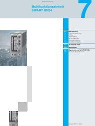
6.6 Travel range limits<br />
Machine data<br />
• The safety-related axis speed can be programmed for all axes of a<br />
process within an NC block by means of MTD_commands.<br />
• The PLC can switch the monitoring of the safety-related axis speed on<br />
and off by means of the axis-specific control signal ‘AxxC.SPEED’.<br />
• The user can recognize the effectiveness of the safety-related axis<br />
speed in the machine data by means of the data element ‘Safetyrelated<br />
speed limit active’.<br />
• After having set the PLC interface signal, the safety-related axis speed<br />
only becomes effective in the next NC block or after an immediate<br />
stop.<br />
• A modified safety-related axis speed only becomes effective in the<br />
next NC block or after an immediate stop.<br />
• Modifications of the nominal value caused by the spindle override are<br />
ignored by the NC.<br />
In addition to the travel range limits defined in the axis parameters<br />
‘Cxx.011’ and ‘Cxx.012’, further travel range limits can be programmed in<br />
the changeable software limits.<br />
Machine data<br />
Limit X+ 122.6000 mm<br />
Limit X- -56.0000 mm<br />
PLC interface signal<br />
Axis parameter<br />
Fig. 6-9: Changeable software limits<br />
Modification by:<br />
- user<br />
- NC<br />
- PLC<br />
Note: The position values are indicated as machine coordinates.<br />
DOK-<strong>MTC200</strong>-NEW*FUN*V19-AW02-EN-P<br />
X<br />
softlimit-en.FH7<br />
The changeable software limits are set for each axis in machine data<br />
page 12.
<strong>New</strong> <strong>Functions</strong> <strong>19VRS</strong> General functions 6-13<br />
PLC interface signal<br />
Boundary conditions<br />
Example<br />
DOK-<strong>MTC200</strong>-NEW*FUN*V19-AW02-EN-P<br />
STRUCT 12 Programmable travel range limits<br />
Prog. travel range limits active BOOL NoNC,NoSPS,NoGUI,NoPwGUI<br />
Prog. travel range limit positive POS NC,SPS,GUI,PwGUI<br />
Prog. travel range limit negative<br />
END_STRUCT<br />
ARRAY [<br />
POS NC,SPS,GUI,PwGUI<br />
Axis no. IP_AXIS 1..12<br />
] OF STRUCT<br />
The machine data elements ’Prog. travel range limit positive’ and ’Prog.<br />
travel range limit negative’ can be modified by the user in the machine<br />
data menu, the NC program and the PLC.<br />
The element ’Prog. travel range limit active’ used for visualization of the<br />
PLC interface signal only allows read access.<br />
• AxxC.LIMIT The axis control signal is used to<br />
activate the changeable software limits.<br />
• AxxC.LIMIT The axis status signal is set as soon as the<br />
control signal has reached the NC.<br />
• The changeable software limits are not effective in NC blocks which<br />
have already been calculated by the block preparation when setting<br />
the control signal ‘AxxC.LIMIT’.<br />
• The changeable software limits must be smaller than the travel range<br />
limits set in the axis parameters.<br />
• If, during activation, the axis is out of the changeable software limits,<br />
the limits only become effective in the next axis movement block.<br />
...<br />
G1 X250 F1500<br />
X100<br />
MTD(12,1,,2)=122.6<br />
X200<br />
...<br />
The positive travel range limit is reduced to 122.6 mm by the<br />
programmable positive travel range limit (the limit set in the axis<br />
parameters is higher). When travelling to X200 after having set the<br />
programmable travel range limit to 122.6, an error is indicated.
6-14 General functions <strong>New</strong> <strong>Functions</strong> <strong>19VRS</strong><br />
6.7 Quick stop upon probe detection<br />
Condition<br />
Functional description<br />
The previously existing probe function was enhanced by the function<br />
"Quick stop upon probe detection". The drives are stopped immediately<br />
when approaching the probe to the measuring point. After completion of<br />
the measuring process, the drives are switched on again.<br />
This function is only possible for DIAX04 drives with firmware SSE03 or<br />
higher.<br />
In addition to the previous probe functionality, the function ‘Quick stop<br />
upon probe detection’ can be selected as of version SSE03.<br />
If the value "5“ is set for position value 1/2 with quick stop at positive edge<br />
in P-0-0200, signal selection probe 1, the drive automatically switches<br />
to "zeroing of nominal speed value" when the positive edge is detected.<br />
This drive state is maintained until the probe-1 enable in parameter S-0-<br />
0405, probe 1 enable is deleted by the control. Then, the drive uses<br />
again the nominal control values.<br />
DOK-<strong>MTC200</strong>-NEW*FUN*V19-AW02-EN-P
<strong>New</strong> <strong>Functions</strong> <strong>19VRS</strong> CNC functions 7-1<br />
7 CNC functions<br />
7.1 Feed to positive stop<br />
Programmable torque<br />
DOK-<strong>MTC200</strong>-NEW*FUN*V19-AW02-EN-P<br />
With "Feed to positive stop G75", it is now possible to set the stop<br />
detection torque and the holding torque separately. The parameterization<br />
takes place via AXD commands.<br />
In addition to the axis parameter ‘Cxx.044 reduced torque at positive<br />
stop’, the torque for feed to positive stop can be set depending on the<br />
machining process in the NC or PLC program via AXD parameters<br />
65017 (P-7-3577) Reduced torque of the digital drive in percentage<br />
for feed to positive stop. The positive stop is<br />
detected at this torque.<br />
65018 (P-7-3578) Reduced torque of the digital drive in percentage<br />
at the positive stop. The value becomes only<br />
effective if it is smaller than the value<br />
programmed in axis parameter ‘Reduced torque<br />
at positive stop’ and less than 100%. The positive<br />
stop is held with this torque.<br />
NC program example<br />
@101=AXD(X:P-7-3577) ; save preset values<br />
@102=AXD(X:P-7-3578)<br />
AXD(X:P-7-3577)=200 ; values required for the machining<br />
process<br />
AXD(X:P-7-3578)=120 ; write (multiplication factor = 40)<br />
G75 X200 F500 ; feed to positive stop<br />
...<br />
G76 ; cancel torque pretension<br />
AXD(X:P-7-3577)=@101 ; restore saved<br />
AXD(X:P-7-3578)=@102 ; preset values<br />
The AXD parameter ‘65017 (P-7-3577)’ is used to set the torque for<br />
positive stop detection. After detecting the positive stop, the axis is held at<br />
the positive stop with the torque set in the AXD parameter ‘65018 (P-7-<br />
3578)’ until the torque pretension is cancelled by means of G76.
7-2 CNC functions <strong>New</strong> <strong>Functions</strong> <strong>19VRS</strong><br />
Example<br />
Fig. 7-1: Feed to positive stop<br />
7.2 Enhanced NC syntax (NC control structures)<br />
Overview<br />
Festanschlag-en.FH7<br />
The following control structures were added to the NC syntax in version<br />
19 and higher:<br />
• IF-ELSE<br />
• FOR<br />
• WHILE<br />
• REPEAT-UNTIL<br />
• SWITCH-CASE<br />
• CONTINUE<br />
• BREAK<br />
One of these instructions can be programmed for each NC block line. A<br />
control structure may contain an instruction or a block of instructions. A<br />
block of instructions is indicated between ‘{’ and ‘}’ An NC block<br />
according to DIN 66025 is considered as an instruction.<br />
Example:<br />
N0001 IF(@10>X) ; control instruction<br />
N0002 Y100 F100 ; instruction if the condition is met<br />
N0003 ELSE<br />
N0004 { ;instruction block if the condition<br />
N0005 Y=@10 ;is not met<br />
N0006 G04 F100<br />
N0007 }<br />
An NC program may consist of an instruction or a list of instructions. The<br />
line feed separates the instructions.<br />
Control instructions can be preceded by the elements: block number,<br />
extended block number, block skip, label and main block detection.<br />
DOK-<strong>MTC200</strong>-NEW*FUN*V19-AW02-EN-P
<strong>New</strong> <strong>Functions</strong> <strong>19VRS</strong> CNC functions 7-3<br />
Conditions in control structures<br />
DOK-<strong>MTC200</strong>-NEW*FUN*V19-AW02-EN-P<br />
Note: Notation in the syntax description.<br />
The character string ‘\n’ in the syntax description means that a<br />
line break has to be inserted at this position. The characters<br />
must not be entered.<br />
The control instructions are controlled by conditions. A condition is<br />
composed of a logic expression.<br />
Example:<br />
N0001 FOR(@10=0,@10
7-4 CNC functions <strong>New</strong> <strong>Functions</strong> <strong>19VRS</strong><br />
Block instructions<br />
IF instruction<br />
The block instruction combines a list of instructions in one instruction.<br />
Example:<br />
N0001 IF(@10
<strong>New</strong> <strong>Functions</strong> <strong>19VRS</strong> CNC functions 7-5<br />
FOR instruction<br />
WHILE instruction<br />
REPEAT UNTIL instruction<br />
DOK-<strong>MTC200</strong>-NEW*FUN*V19-AW02-EN-P<br />
The FOR loop allows to repeat an instruction until the cancel condition is<br />
met. The loop variable is initialized at the beginning of the instruction and<br />
increased with each run according to the increment.<br />
Example:<br />
N0001 FOR(@10=0,@100 )<br />
N0002 {<br />
N0003 @12=@12+@10 X@12 Y@10<br />
N0004 @10=@10-1<br />
N0005 }<br />
The blocks N0003 and N0004 are repeated until @10=0.<br />
Syntax description:<br />
WHILE instruction = ‘WHILE’ ‘(’ condition ‘)’ ‘\n’<br />
instruction.<br />
The REPEAT UNTIL instruction repeats the instructions between<br />
REPEAT and UNTIL until the UNTIL condition is met.<br />
Example:<br />
N0001 REPEAT<br />
N0002 ....<br />
N0011 UNTIL(@10>100 || @12==@11 )<br />
The block between REPEAT and UNTIL is executed at least once<br />
and is repeated until @10>100 or @12=@11.<br />
Syntax description:<br />
REPEAT instruction = ‘REPEAT’ ‘\n’<br />
{ instruction }<br />
‘UNTIL’ ‘(‘ condition ‘)’ ‘\n’.
7-6 CNC functions <strong>New</strong> <strong>Functions</strong> <strong>19VRS</strong><br />
CONTINUE instruction<br />
BREAK instruction<br />
The CONTINUE instruction continues the machining process with the<br />
next loop run. The loop counter is increased and the condition is checked<br />
within the FOR instruction. The WHILE and UNTIL instructions continue<br />
the checking of the condition.<br />
Example:<br />
N0000 @100=10<br />
N0001 WHILE( @100 > 0 ) ;repeat as long as @100>0<br />
N0002 { ; block start<br />
N0003 @100=@100-1 ; decrease loop counter<br />
N0004 IF( OTD(,,@100,4,0) == 0 ) ; offset in zero offset table =<br />
0?<br />
N0007 CONTINUE ; yes, address next memory<br />
N0010 BSR .KONTUR ; contouring<br />
N0011 } ; end of While instruction<br />
Syntax description:<br />
CONTINUE instruction = ‘CONTINUE’ ‘\n’<br />
The BREAK instruction interrupts a loop.<br />
Example:<br />
N0001 FOR(@1=0,@1
<strong>New</strong> <strong>Functions</strong> <strong>19VRS</strong> CNC functions 7-7<br />
SWITCH instruction<br />
Indexable NC variables<br />
DOK-<strong>MTC200</strong>-NEW*FUN*V19-AW02-EN-P<br />
The SWITCH instruction allows the programming of a jump distributor.<br />
Depending on the value of the SWITCH expression, a CASE label is<br />
addressed. An instruction block may be preceded by several CASE<br />
labels. Branching to the end of the SWITCH instruction takes place after<br />
an instruction block. The DEFAULT label is addressed if no CASE label<br />
applies. If, in this case, the DEFAULT label is not available, branching to<br />
the end of the SWITCH instruction takes place.<br />
Example:<br />
N0001 SWITCH(G(17)) ; active transformation?<br />
N0002 {<br />
N0003 CASE 30: ;G30<br />
N0004 G31 X1 10 Y2 10 F100 ; activate Transmit<br />
N0005 CASE 31: ;G31<br />
N0006 BSR .KONTUR ; contouring<br />
N0007 DEFAULT: ;G32<br />
N0008 G30 C0 F200 ; switch off transformation<br />
N0009 }<br />
Syntax description:<br />
SWITCH instruction = ‘SWITCH’ ‘(’ math. expression ‘)’ ‘\n’<br />
‘{‘ ‘\n’<br />
{{ ‘CASE integer ‘:’ ‘\n’ }<br />
{ instruction }}<br />
[ ‘DEFAULT’ ‘:’ ‘\n’<br />
instruction ]<br />
‘}’ ‘\n’<br />
In order to use the NC variables as fields in conjunction with the loop<br />
instructions "while", "for" and "until", indirect addressing is introduced in<br />
addition.<br />
Syntax description:<br />
NC-Var = @0..255<br />
| @0..6:0..255<br />
| @[ math. expression ] ; new<br />
| @[ math. expression ]:[ math. expression ]. ; new<br />
Example:<br />
N0000 G01 F1000<br />
N0001 FOR(@1=0,@1
7-8 CNC functions <strong>New</strong> <strong>Functions</strong> <strong>19VRS</strong><br />
7.3 Adaptive feed control (G26)<br />
Boundary conditions<br />
Syntax<br />
The adaptive feed control allows to modify the feedrate of an axis or the<br />
path velocity of the interpolating axes depending on the motor<br />
current/torque of a spindle or feed axis so that the machining capacity or<br />
machining volume (during milling, turning or grinding) remains constant.<br />
Thus, it is possible to obtain<br />
• an improved surface quality,<br />
• shorter machining times and<br />
• to protect the tool, workpiece and machine against overload.<br />
The function is activated by parameter B00.062. The feed control<br />
parameters are available in machine page 30.<br />
• The adaptive feed control can be used in conjunction with digital<br />
spindles/feed axes with SERCOS interface.<br />
• All axes and spindles involved in the adaptive feed control must be<br />
part of a process. This means that the reference axis must be part of<br />
the process of which the feedrate is to be controlled.<br />
• All axes and spindles (including the feed axes involved in the<br />
interpolation) involved in the adaptive feed control must be connected<br />
to an axis processor. (The CPU informs the APR to which axes the<br />
internal override is to be distributed.)<br />
• The adaptive feed control cannot be used for the following functions:<br />
- axis homing cycle (G74),<br />
- feed to positive stop (G75).<br />
• Furthermore, the adaptive feed control is only available in the<br />
operating modes automatic, semi-automatic and MDI.<br />
• The NC deactivates the adaptive feed control automatically (and sets<br />
G25) upon control reset and end of program.<br />
G25 Switch off adaptive feed control (switch-on state)<br />
G26 Switch on adaptive feed control<br />
DOK-<strong>MTC200</strong>-NEW*FUN*V19-AW02-EN-P
<strong>New</strong> <strong>Functions</strong> <strong>19VRS</strong> CNC functions 7-9<br />
Parameters<br />
Machine parameters<br />
PLC interface signals<br />
Type<br />
Designation<br />
Meaning<br />
DOK-<strong>MTC200</strong>-NEW*FUN*V19-AW02-EN-P<br />
If the manufacturer answers the process parameter "adaptive feed<br />
control" with "Yes", further process parameters follow<br />
• Bxx.063 Reference axis for adaptive feed control<br />
• Bxx.064 Nominal machining torque<br />
• Bxx.065 Minimum machining torque<br />
• Bxx.066 Maximum idling torque<br />
• Bxx.067 Maximum feed reduction<br />
• Bxx.068 Amplification<br />
• Bxx.069 Measuring period<br />
The process-specific page "adaptive feed control" (page 30) is structured<br />
as follows:<br />
Fig. 7-2: Structure of machine data page 30<br />
MPage30.bmp<br />
With the "adaptive feed control" function, two new PLC interface signals<br />
were introduced. These signals are used for measuring result analysis.<br />
• PxxS.THMIS „Thrust Missing“ depending on process parameter<br />
Bxx.065 and<br />
• PxxS.EXCTH „Excessive Thrust“ depending on process parameter<br />
Bxx.064.<br />
Thrust Missing<br />
Process status signal<br />
PxxS.THMIS (THrust MISsing)<br />
PxxS.THMIS = 1:<br />
The machining torque did not exceed the specified minimum machining<br />
torque Bxx.065 during the machining process.<br />
PxxS.THMIS = 0:<br />
The machining torque exceeded the specified minimum machining<br />
torque Bxx.065 during the machining process.
7-10 CNC functions <strong>New</strong> <strong>Functions</strong> <strong>19VRS</strong><br />
Update<br />
Method of operation<br />
Type<br />
Designation<br />
Meaning<br />
Update<br />
Method of operation<br />
The NC updates the interface signal after switching the adaptive feed<br />
control on (G26) and off (G25). The NC resets this signal upon program<br />
end and control reset.<br />
If the machining torque does not exceed the minimum machining torque<br />
Bxx.065 during machining with activated adaptive feed control, the NC<br />
indicates this by setting the interface signal "Thrust Missing"<br />
(PxxS.THMIS) when switching off the adaptive feed control.<br />
Excessive Thrust<br />
Process status signal<br />
PxxS.EXCTH (EXCessive THrust)<br />
PxxS.EXCTH=1:<br />
The current feed reduction exceeds the maximum feed reduction<br />
Bxx.067.<br />
PxxS.EXCTH=0:<br />
The current feed reduction does not exceed the maximum feed<br />
reduction Bxx.067.<br />
The NC updates the interface signal when switching the adaptive feed<br />
control on (G26) and off (G25). The NC resets this signal upon program<br />
end and control reset.<br />
If the current feed reduction exceeds the maximum feed reduction<br />
Bxx.067 during machining with activated adaptive feed control, the NC<br />
indicates this by setting the interface signal "Excessive thrust"<br />
(PxxS.EXCTH).<br />
Note: The NC continues the machining process regardless of<br />
whether or not the current feed reduction exceeds the<br />
maximum feed reduction. Only if the current feed reduction<br />
reaches 100% (i. e. feedrate = 0 mm/min) and the set<br />
maximum feed reduction Bxx.067 or machine data variable<br />
013 is less than 100%, the NC stops the machining and<br />
generates the error message .510 "100% feed reduction @<br />
axis".<br />
DOK-<strong>MTC200</strong>-NEW*FUN*V19-AW02-EN-P
<strong>New</strong> <strong>Functions</strong> <strong>19VRS</strong> CNC functions 7-11<br />
Problem of „inclined axis“<br />
Parameterization<br />
DOK-<strong>MTC200</strong>-NEW*FUN*V19-AW02-EN-P<br />
In case of "inclined axis without counter force", a torque for holding the<br />
axis in position is required. This holding torque is added as offset to all<br />
indicated torques. The torques required for the adaptive feed control are<br />
distorted.<br />
Note: The adaptive feed control is not possible when an inclined axis<br />
is used as reference axis.<br />
Solution:<br />
The torque offset (stall torque) required for holding the axis must be<br />
eliminated for the adaptive feed control.<br />
To do so, a command for recording the stall torque is required.<br />
Stall torque recording is possible with the commands<br />
• ITM or<br />
• AXD.<br />
The reference axis indicated in the parameters or machine data is<br />
referred to. The stall torque is included in the torque generation during the<br />
adaptive feed control.<br />
The stall torque is generated during the dwell time indicated in the<br />
machine data.<br />
The machine data has to be extended:<br />
adaptive feed control active<br />
reference axis<br />
amplification<br />
<strong>New</strong> measuring period stall torque<br />
<strong>New</strong> stall torque<br />
measuring period idling torque<br />
idling torque<br />
maximum idling torque<br />
current machining torque<br />
peak machining torque<br />
minimum machining torque<br />
limiting machining torque<br />
current feed reduction<br />
peak feed reduction<br />
maximum feed reduction<br />
The parameters for measuring period stall torque and stall torque have<br />
the same unit and priorities as the parameters for measuring period idling<br />
torque and idling torque.<br />
The torque generated by STM is saved in the stall torque parameter.<br />
The feed adaptation function is controlled by machine data page 30<br />
"adaptive feed control". If no reference axis (=0) was entered in the<br />
machine data page, the following parameter data is stored:<br />
= <br />
002 Reference axis = B0x.062 Reference axis for adaptive feed control<br />
003 Amplification = B0x.068 Amplification
7-12 CNC functions <strong>New</strong> <strong>Functions</strong> <strong>19VRS</strong><br />
Additional documentation<br />
004 Measuring period = B0x.069 Measuring period<br />
006 Max. idling torque = B0x.066 Max. idling torque<br />
009 Min. machining torque = B0x.065 Min. machining torque<br />
010 Limiting machining torque= B0x.064 Limiting machining torque<br />
013 Max. feed reduction = B0x.067 Max. feed reduction<br />
A detailed description of the function is available under the order number<br />
DOK-<strong>MTC200</strong>-AD*FEED*V19-FK01-EN-P<br />
7.4 Switchover to second encoder system (Adaptive Depth)<br />
Application<br />
<strong>New</strong> axis parameters<br />
Adaptive Depth supports a second encoder system which is, for example,<br />
used for the compensation of workpiece clamping errors (surface probe).<br />
The second encoder is parameterized in the axis parameters Cxx.087,<br />
Cxx.088, Css.089, Css.090 and Cxx.091. The switchover is carried out<br />
with the G code G69 while the probe is deflected. Switching back to the<br />
encoder system 1 takes place with G68 while the probe is still deflected.<br />
Application 1<br />
Adaptive positioning with linear probe. The switchover takes place during<br />
movement.<br />
Application 2<br />
Switchover from motor encoder to external measuring system. The<br />
external measuring system may be a linear probe, rotary encoder in case<br />
of circular axes or a linear probe. Switchover takes place when stopped<br />
but with power on and controller enabled.<br />
If motor encoder was selected in the axis parameter "position transmitter<br />
arrangement", further axis parameters are available for switching over to<br />
a second encoder system.<br />
• Cxx.087 Adaptive control<br />
• Cxx.088 Reference value of 2 nd encoder system<br />
• Cxx.089 Positive travel range limit of 2 nd encoder system<br />
• Cxx.090 Negative travel range limit of 2 nd encoder system<br />
• Cxx.091 Admissible predeflection of probe in 1 st encoder system<br />
G codes for switchover to second encoder system<br />
Two new G codes are available for switching between two encoder<br />
systems.<br />
• G69 switches over to the second encoder.<br />
• G68 switches back to the motor encoder.<br />
The G codes are effective in the operating modes.<br />
If the G code G69 is executed when preselecting G09, switchover to the<br />
second encoder takes place when stopped. When preselecting G08, the<br />
axis coordinate value is approached as target position in the second<br />
encoder system.<br />
DOK-<strong>MTC200</strong>-NEW*FUN*V19-AW02-EN-P
<strong>New</strong> <strong>Functions</strong> <strong>19VRS</strong> CNC functions 7-13<br />
7.5 Test mode<br />
Purpose<br />
DOK-<strong>MTC200</strong>-NEW*FUN*V19-AW02-EN-P<br />
Examples:<br />
Suppressing the help function output<br />
Locking axes and spindles<br />
Simple milling machine<br />
Simple lathe<br />
Complex machine<br />
G69 G09 X0 ; switchover when stopped<br />
G69 G08 X200 ; approach target position in encoder system 2<br />
In addition to the existing functions such as single block mode, semiautomatic<br />
mode, spindle override, rapid feed override, block skip,<br />
conditional and unconditional stop, as well as virtual NC including (offline)<br />
simulation, the new functions such as<br />
• help function output,<br />
• locking of movements,<br />
• test feed,<br />
• rapid program execution and<br />
• graphical online simulation<br />
allow the user faster commissioning.<br />
The new functions – in the following called “test mode” – allow the user to<br />
concentrate directly on the geometry, process synchronization and<br />
collision protection. By means of these functions, the complete process<br />
and especially the parallel sequences of a run can be viewed separately<br />
and repeated at any speed as often as required. This is possible with and<br />
without I/O level activation and with and without axis movements.<br />
The function “suppress help function output” allows the machine operator<br />
to switch off special help functions (e. g. coolant) or all help functions (M,<br />
Q, S and T/E functions) during the test mode.<br />
The operator can activate the function “suppress help function” by<br />
pressing an M key.<br />
Application<br />
The function “lock axes and spindles” allows the operator to switch on and<br />
off certain axes and spindles and to test the program step-by-step.<br />
Examples<br />
The test mode on a milling machine allows the operator to lock the feed<br />
axis (Z axis) by pressing an M key and to select a higher speed (test feed)<br />
for program execution.<br />
During the subsequent test mode, the tool change is carried out like in<br />
normal program mode.<br />
The test mode of a lathe is similar. By pressing an M key, all axes (X, Z<br />
and W (tool turret)) and the spindle are locked and the test feed is<br />
activated.<br />
From the creation of the NC program to the production of the part, the<br />
following steps (test stages) are carried out for example:<br />
1. The operator can activate the following functions by means of M keys:<br />
- lock all main axes (X, Z), turret and spindle (S),<br />
- lock secondary axes (U (steady), V (tailstock),<br />
- activate test feed and
7-14 CNC functions <strong>New</strong> <strong>Functions</strong> <strong>19VRS</strong><br />
Further application<br />
- suppress help function output.<br />
The operator switches on the online graphics before starting the<br />
program.<br />
2. After successful program execution, the operator cancels the locking<br />
of the main axes, tool turret and spindle by pressing an M key and<br />
runs the NC program again (without part). The user checks the<br />
correction data (zero offsets, tool offsets,...) by means of the traversed<br />
path.<br />
3. Then, the operator switches on the secondary axes (U, V) and checks<br />
their movements with regard to collision.<br />
4. After this stage has been completed successfully, the operator<br />
deactivates the function “suppress help function output” and checks<br />
the help functions displayed while the run is repeated.<br />
Then, the part is machined.<br />
The axis/spindle lock is not only used for test purposes but also for other<br />
purposes. It is for example also used for dual lathes or milling machines,<br />
which are operated as a dual machine or as two individual machines.<br />
DOK-<strong>MTC200</strong>-NEW*FUN*V19-AW02-EN-P
<strong>New</strong> <strong>Functions</strong> <strong>19VRS</strong> CNC functions 7-15<br />
Test feed<br />
Application<br />
Method of operation<br />
Selection of the test feed<br />
Entry of test feed<br />
DOK-<strong>MTC200</strong>-NEW*FUN*V19-AW02-EN-P<br />
The test feed allows a fast NC program run. This is especially favorable if<br />
axes and spindles are locked. Furthermore, smooth execution of the<br />
machining processes as well as smooth approaching and moving away<br />
are possible.<br />
The test feed is used for program execution instead of the programmed<br />
feed when selection the function “test feed” in the operating modes<br />
automatic and semi-automatic.<br />
With the function “test feed” activated, the NC moves the axes<br />
programmed in connection with G01, G02, G03, G33, G63, G64, G65,<br />
G74, G75 and G77 at the test feed. This feed value is also used for G95<br />
(feed per revolution) regardless of the respective spindle speed.<br />
In case of G00, the NC moves the axes at a second test feed (rapid test<br />
feed) with the function “test feed” activated.<br />
The function “test feed” is always available for the user during the test<br />
mode, regardless of whether the axes or spindles are locked or not.<br />
With the test feed activated, feed and rapid feed override have the same<br />
effect as during normal operation. As in normal operation, the NC avoids<br />
that the maximum axis speeds defined in the machine parameters and<br />
the maximum path velocity are exceeded.<br />
The machine operator selects the test feed via the user interface by using<br />
an M key.<br />
Upon selection, the interface signal PxxCDRYRN (DRY RuN) is<br />
transferred to the NC and the machine data element "test feed“ is set if it<br />
has not been set before.<br />
Note: During the configuration of the function within the GUI, assure<br />
that “test mode” is displayed as sub-mode on the GUI screens.<br />
The values for the test feedrates “test feed” and “rapid test feed" are to be<br />
entered by the machine manufacturer in machine data page “test mode”<br />
and may be overwritten by the end-user directly in the machine data or<br />
indirectly via the PLC. The machine manufacturer may, for example,<br />
propose values for test feed and rapid test feed via the M keys thus<br />
enabling the end-user to make his selection.
7-16 CNC functions <strong>New</strong> <strong>Functions</strong> <strong>19VRS</strong><br />
Rapid program execution<br />
Application<br />
Online simulation<br />
Application<br />
The rapid program execution is the fastest way to check an NC program.<br />
It can be carried out by using the block scan whereby the operator does<br />
not need to select a start or target block. As in normal operation, the NC<br />
starts with the first NC block and stops as soon as the program end is<br />
reached. The axes and spindles are not moved during this process and<br />
only the help functions defined in the machine parameters (Bxx.058 -<br />
Bxx.061) are output.<br />
This function allows to quickly check tool offsets, zero offsets and D<br />
corrections with regard to travel range limits or variable calculations, etc.<br />
The online simulation can be switched on and off in all operating modes<br />
and sub-modes and gives the user reliable information about the travelled<br />
path of the (moved or locked) axes within the machine.<br />
Suppressing tool transfer and tool movements<br />
Application<br />
Note: In case of very short NC blocks (e. g. transition radiuses) and<br />
very high path velocities, the online simulation may possibly<br />
not cover all NC blocks. These are not shown within the<br />
graphics or marked by arrows or points.<br />
The function “suppress tool transfer and tool movement” constitutes an<br />
important partial function of an NC program test during the execution of<br />
which the tool storage axis is locked and the help functions are not output.<br />
It allows the machine manufacturer to freeze or to use the tool list during<br />
the test mode, if required. The freezing of the tool list is especially<br />
required if, during the test mode, the appropriate tool storage axis is<br />
locked and the tool-change-specific help functions are not processed in<br />
the PLC.<br />
Note: During commissioning, ensure that when locking the tool<br />
storage axis the tool-change-specific help functions are not<br />
processed in the PLC and the tool list is frozen!<br />
DOK-<strong>MTC200</strong>-NEW*FUN*V19-AW02-EN-P
<strong>New</strong> <strong>Functions</strong> <strong>19VRS</strong> PLC functions 8-1<br />
8 PLC functions<br />
8.1 Switching from PEA external to PEA internal<br />
Procedure:<br />
DOK-<strong>MTC200</strong>-NEW*FUN*V19-AW02-EN-P<br />
The enhancement of PC board MTS-P01.1 to MTS-P01.2/2.2 allowed to<br />
integrate the PEA in the board. The additional PC104 board is no longer<br />
required. This, however, requires an I/O configuration modification in<br />
programs developed for MTS-P01.1 with PEA (BTV20 with BTA20).<br />
1. Save PLC program in ASCII format, menu File – ASCII store.<br />
2. Switch to the clipboard by pressing + and search the<br />
following entry within the section IO:<br />
LOOP AT (**): 16#E000 ’PEA3/4’<br />
MASTER<br />
(*) AT 1: 16#0001 ’input core image storage’<br />
MODULE<br />
AT 0..2: 16#0001 ’IB’<br />
END_MODULE<br />
(*) AT 2: 16#0002 ’output core image storage’<br />
MODULE<br />
AT 0..2: 16#0002 ’QB’<br />
END_MODULE<br />
END_MASTER<br />
END_LOOP<br />
3. Modify entry LOOP AT (**): 16#..... in LOOP_INTERN AT 4: 16#....<br />
and remove the keywords MASTER and END_MASTER.<br />
Then, the entry must read as follows:<br />
LOOP_INTERN AT 4: 16#E000 ’PEA3/4’<br />
(*) AT 1: 16#0001 ’input core image storage’<br />
MODULE<br />
AT 0..2: 16#0001 ’IB’<br />
END_MODULE<br />
(*) AT 2: 16#0002 ’output core image storage’<br />
MODULE<br />
AT 0..2: 16#0002 ’QB’<br />
END_MODULE<br />
END_LOOP<br />
(**) corresponds to the slot number according to the current configuration<br />
(1...4)<br />
(*) corresponds to the unchanged logic user numbers of the original<br />
configuration (1...999)<br />
4. Mark the complete clipboard.<br />
5. Load the ASCII file by means of menu File – ASCII load.
8-2 PLC functions <strong>New</strong> <strong>Functions</strong> <strong>19VRS</strong><br />
Script control<br />
The conversion can be carried out automatically by means of the script<br />
control:<br />
SCRIPT PEA1_DE pea external -><br />
internal German<br />
KEY Alta KEY del<br />
KEYS I<br />
KEY del<br />
DELAY 250 KEY del<br />
KEY Enter KEY del<br />
KEY AltB KEY del<br />
KEY CtrlQ KEY down<br />
KEYS F<br />
KEY down<br />
KEYS PEA KEY down<br />
DELAY 200 KEY down<br />
KEY Enter KEY down<br />
KEY Home KEY down<br />
DELAY 200 KEY down<br />
KEY right KEY down<br />
KEY right KEY down<br />
KEY right KEY del<br />
KEY right KEY del<br />
KEY right KEY del<br />
KEY right KEY del<br />
KEY right KEY del<br />
KEY right KEY del<br />
DELAY 200 KEY del<br />
KEYS _INTERN KEY del<br />
KEY right KEY del<br />
KEY right KEY del<br />
KEY right KEY del<br />
KEY right KEY del<br />
KEYS 4<br />
KEY del<br />
KEY DEL KEY del<br />
KEY down KEY del<br />
KEY Home KEY del<br />
KEY Del KEY AltA<br />
KEY del KEYS c<br />
KEY del DELAY 250<br />
KEY del KEY Enter<br />
KEY del KEY F2<br />
KEY del KEY Alti<br />
KEY del DELAY 250<br />
EXIT<br />
Fig. 8-1: Script control for automatic adaptation<br />
SCRIPT PEA2_EN pea external -><br />
internal English<br />
KEY Altf KEY del<br />
KEYS I<br />
KEY del<br />
DELAY 250 KEY del<br />
KEY Enter KEY del<br />
KEY AltB KEY del<br />
KEY CtrlQ KEY down<br />
KEYS F<br />
KEY down<br />
KEYS PEA KEY down<br />
DELAY 200 KEY down<br />
KEY Enter KEY down<br />
KEY Home KEY down<br />
DELAY 200 KEY down<br />
KEY right KEY down<br />
KEY right KEY down<br />
KEY right KEY del<br />
KEY right KEY del<br />
KEY right KEY del<br />
KEY right KEY del<br />
KEY right KEY del<br />
KEY right KEY del<br />
DELAY 200 KEY del<br />
KEYS _INTERN KEY del<br />
KEY right KEY del<br />
KEY right KEY del<br />
KEY right KEY del<br />
KEY right KEY del<br />
KEYS 4<br />
KEY del<br />
KEY DEL KEY del<br />
KEY down KEY del<br />
KEY Home KEY del<br />
KEY Del KEY Altf<br />
KEY del KEYS c<br />
KEY del DELAY 250<br />
KEY del KEY Enter<br />
KEY del KEY F2<br />
KEY del KEY Alti<br />
KEY del DELAY 250<br />
EXIT<br />
DOK-<strong>MTC200</strong>-NEW*FUN*V19-AW02-EN-P
<strong>New</strong> <strong>Functions</strong> <strong>19VRS</strong> PLC functions 8-3<br />
8.2 BT bus as I/O page<br />
Addressing<br />
DOK-<strong>MTC200</strong>-NEW*FUN*V19-AW02-EN-P<br />
The BT bus can be used to connect up to four operator panels of type<br />
BTM15/16 or BTA20. The maximum length of the BT bus may be up to 50<br />
m (from the connection point to the last user). This applies to the<br />
connection of only one device and the permissible maximum number of 4<br />
devices. It is not possible to directly access the I/O data of the operator<br />
panels from the PLC (e.g. %IBP*.*). Data is exclusively exchanged via the<br />
core image storage. A wide transmission speed range can be adjusted, a<br />
default value of 19200 baud makes sense. An increase to 38400 baud is<br />
possible but increases the cycle time considerably.<br />
The address assignments required for programming can be found in the<br />
concerning documents of the devices to be connected.<br />
The BT bus is addressed by assigning a logic user number in the I/O<br />
editor of the PLC programming interface. Each input core image storage<br />
as well as each output core image storage is assigned its own logic<br />
address.<br />
Fig. 8-2: BT storage page<br />
io_bt-bus.bmp<br />
Each of the two core image storages has a size of 128 bytes, which are<br />
available for the connected operating devices. The number of bytes<br />
assigned in the core image storage depends on the operating device.<br />
Device type Storage assignment in the input/output core image<br />
BTM15 Depending on the configuration<br />
2 bytes for digital I/Os (always assigned)<br />
2 additional bytes for each module (except handwheel)<br />
4 additional bytes for handwheel module<br />
BTM16 14 bytes<br />
BTM20 6 bytes<br />
Fig. 8-3: Storage requirements of operating devices<br />
Depending on the physical order of the operating devices connected to<br />
the BT bus, the device addresses are assigned in the input and output<br />
core image storage without any gaps, according to the storage<br />
requirements of the operating devices. The example BT-Bus.bmp shows<br />
the principle of the BT bus storage assignment.
8-4 PLC functions <strong>New</strong> <strong>Functions</strong> <strong>19VRS</strong><br />
Indramat<br />
OPERATOR PROGRAMMER<br />
BTV20/30<br />
MTS-P<br />
X15<br />
IKS 0056 BT bus<br />
IKS 0056<br />
BT bus<br />
Up to 2 further<br />
operator terminals<br />
in BT bus<br />
TEMP HD POWER<br />
E-STOP<br />
Indramat<br />
MASCHINE<br />
EIN<br />
MASCHINE<br />
AUS<br />
BTA20<br />
BETRIEBSART<br />
Fig. 8-4: Addressing example BT bus<br />
AUTO<br />
START<br />
LOCAL<br />
MACHINE CONTROL<br />
BTM16<br />
10 20 30 40<br />
8 50<br />
6<br />
60<br />
4<br />
70<br />
2<br />
80<br />
1<br />
100<br />
0<br />
120<br />
%<br />
75 80 85 90<br />
70 95<br />
65<br />
100<br />
60<br />
105<br />
55<br />
110<br />
50<br />
115<br />
45<br />
120<br />
%<br />
%<br />
10<br />
20 30<br />
40 F<br />
8 50<br />
6<br />
60<br />
4<br />
70<br />
2<br />
80<br />
1<br />
100<br />
0<br />
120<br />
ZUSTIMM-<br />
TASTER<br />
-<br />
ANSCHLUß<br />
HANDBEDIEN-<br />
GERÄT<br />
0<br />
90<br />
10<br />
80<br />
20<br />
70<br />
30<br />
60<br />
40<br />
50<br />
8.3 Parameters for setting the data consistency at the<br />
Interbus<br />
+<br />
BT-Bus_übers-en.bmp<br />
In the past (Interbus), the data exchange between the PLC and the field<br />
bus interface was carried out freely and asynchronously.<br />
Data consistency could therefore only be guaranteed for one word (16<br />
bits) (quickest method to exchange data between two systems).<br />
Since more and more modules are required for which the data<br />
consistency per word is not sufficient, a consistent access to a larger<br />
range should be possible. Since the PLC has a higher cycle time than the<br />
field bus, the consistency must be controlled by the PLC.<br />
For this reason, a buffered and PLC-controlled version guaranteeing the<br />
consistency for the complete field bus is offered. This version controlled<br />
by certain handshake bits is slower and should therefore only be used as<br />
an option.<br />
An access mechanism for this option was implemented via the pop-up menu<br />
(+) of the I/O editor (see also Fig. 8-5: Switch data<br />
consistency in Interbus parameter<br />
DOK-<strong>MTC200</strong>-NEW*FUN*V19-AW02-EN-P
<strong>New</strong> <strong>Functions</strong> <strong>19VRS</strong> PLC functions 8-5<br />
DOK-<strong>MTC200</strong>-NEW*FUN*V19-AW02-EN-P<br />
Fig. 8-5: Switch data consistency in Interbus parameter<br />
8.4 Control of the Interbus system (IBM2, G4)<br />
Conditions<br />
Datenkonsistenz.bmp<br />
The following user function blocks are available in the PLC programming<br />
interface for the control of the Interbus system (IBM2, G4).<br />
CLR_DIAG: clear diagnosis parameter register<br />
SEG_OFF: switch off segment<br />
SEG_ON: switch on segment<br />
STOP_D: stop data transfer<br />
START_D: start data transfer<br />
These blocks allow to exchange Interbus modules during bus operation or<br />
to switch Interbus sections on and off independently. Furthermore, the<br />
diagnosis parameter registers can be cleared in order to be able to react<br />
to active messages (failing peripheral units, etc.).<br />
Before using the function blocks, the following actions have to be carried<br />
out:<br />
• Enter the standard registers of the Interbus interface in the I/O editor<br />
of the Interbus master interface by assigning a logic user number.<br />
Please observe that these registers can only be entered after the last<br />
bus node.<br />
• Diagnosis status register<br />
(designation in the IBS list: DiagnosisStatusReg)<br />
• Diagnosis parameter register<br />
(designation in the IBS list: DiagnosisParameterReg)<br />
• Function status register<br />
(designation in the IBS list: FunctionStatusReg)<br />
• Function parameter register<br />
(designation in the IBS list: FunctionParameterReg)<br />
• Function start register<br />
(designation in the IBS list: FunctionStartReg)<br />
The blocks are to be imported into the programming interface by means<br />
of the menu Project – Archive - Fetch.<br />
• Entry of the required blocks in the import list.<br />
• Declaration of function blocks in the declaration editor.
8-6 PLC functions <strong>New</strong> <strong>Functions</strong> <strong>19VRS</strong><br />
8.5 Possible faults during the start-up of IBS G4 and their<br />
elimination<br />
Example<br />
Error elimination<br />
Values entered in the IBS interface are valid until they are overwritten by<br />
the same service or the interface is reset. If, now, two programs with<br />
different start-up services are successively transferred to the control,<br />
addresses can be relocated.<br />
Program 1 is a new program of version V19 with the required start-up<br />
sequence (Set_Value – Load_Configuration –<br />
Load_Process_Data_Reference_List)<br />
Program 2 is an older program with physical addressing containing only<br />
the simple start-up (Load_Configuration);<br />
If now the start-up services of program 1 are transferred to the IBS<br />
interface, the IBS interface takes the base addresses for the process data<br />
from the service 0x750 – "Set_Value“. These base addresses remain also<br />
valid after the start-up services of program 2 have been transferred; since<br />
they do not contain the service 0.750 – Set_Value and the interface has<br />
not been reset in the meantime, the value transferred first remains valid.<br />
The automatic parameterization of the process data channel, carried out<br />
by the interface after service 0.308, is based on the base addresses of<br />
the start-up services of program 1. The PLC GUI, however, does not<br />
include these base addresses in the calculation of the individual user<br />
addresses.<br />
This error can only be eliminated by a control reset (possibly by a<br />
software reset if an error is active).<br />
DOK-<strong>MTC200</strong>-NEW*FUN*V19-AW02-EN-P
<strong>New</strong> <strong>Functions</strong> <strong>19VRS</strong> Tool management functions 9-1<br />
9 Tool management functions<br />
9.1 Flexible equipment check<br />
No equipment check upon reverse start<br />
9.2 Movement indication PLC turret<br />
9.3 Modifications<br />
Remaining tool life<br />
TID<br />
DOK-<strong>MTC200</strong>-NEW*FUN*V19-AW02-EN-P<br />
The process signal PccC.MGWTC (magazine without tool check) -<br />
formerly PxxC.F62 - allows to suppress the automatic equipment check<br />
(tool list vs. set-up list) at the beginning of the forward program start. It<br />
can be started at a later time from the NC program.<br />
Tool Identification<br />
An equipment check can be carried out during an NC program by using<br />
the NC command TID.<br />
This function is especially required in connection with background<br />
magazines.<br />
The equipment check function and the individual actions carried out after<br />
releasing the check are described in the document "Tool management".<br />
No equipment check is carried out in version 19 upon a reverse start.<br />
Thus, starting the reverse program is always possible. If, however, an<br />
equipment check should be carried out in the reverse program, the NC<br />
command ’TID’ has to be programmed in the reverse program.<br />
The tool management always indicates a movement for PLC-controlled<br />
turrets. In case of NC-controlled turrets, however, a movement is only<br />
indicated if a turret movement is necessary (nominal position ≠ actual<br />
position).<br />
From version 19 and higher, the automatic suppression of unnecessary<br />
tool axis movements will only be possible for NC-controlled tool drives. If<br />
required, a corresponding logic must be provided in the PLC user<br />
program for PLC-controlled tool drives. This allows cutting with a<br />
complete revolution of the tool drive by selecting the same tool<br />
repeatedly.<br />
The value range of the remaining tool life has been extended:<br />
previously: 0,00 to 100,00<br />
now: -99,99 to 100,00<br />
By means of the extended value range of the remaining tool life, it is<br />
possible to find out whether a worn tool was still used and if yes, for how<br />
long.
9-2 Tool management functions <strong>New</strong> <strong>Functions</strong> <strong>19VRS</strong><br />
DOK-<strong>MTC200</strong>-NEW*FUN*V19-AW02-EN-P
<strong>New</strong> <strong>Functions</strong> <strong>19VRS</strong> Parameters/interface signals 10-1<br />
10 Parameters/interface signals<br />
10.1 Maintaining the reference system upon control reset<br />
Purpose<br />
Parameter designation<br />
Parameter number<br />
Value range<br />
Default setting<br />
Unit<br />
From version:<br />
DOK-<strong>MTC200</strong>-NEW*FUN*V19-AW02-EN-P<br />
This parameter allows to determine whether, upon a control reset, the<br />
active zero offset and the active tool length offset are initialized according<br />
to the switch-on state or whether the currently active state is maintained.<br />
Maintain reference system upon control reset<br />
Bxx.070<br />
YES/NO<br />
NO<br />
---<br />
>= 04.19<br />
If the parameter is set to NO, the following initializations are carried out<br />
upon a control reset:<br />
• The active zero offset is deactivated and the zero offset (G53 G59)<br />
entered in process parameter Bxx.039 (stored zero offset) is<br />
activated.<br />
• The active zero point memory is set to ‚0‘.<br />
• The active tool length offset is deactivated and the tool length offset<br />
(G47 G49) entered in process parameter Bxx.038 (stored tool length<br />
offset) is activated.<br />
• The active D correction is set to ‚0‘, i. e. it is deactivated.<br />
If the parameter is set to YES, the following states are maintained upon a<br />
control reset:<br />
• The active zero offset (G53..G59)<br />
• The active zero point memory<br />
• The active tool length offset (G47..G49)<br />
• The active D correction (0..99)<br />
Note: Upon program end with return (RET) and back with stop<br />
(BST), the default state stored in the process parameters is<br />
activated, i. e. parameter Bxx.070 has the same effect as if the<br />
parameter was set to NO.<br />
10.2 Axis transfer for all processes possible<br />
Up to now, it was possible to transfer axes to a maximum of 4 different<br />
processes. By entering an asterisk (*) in axis parameter Cxx.000<br />
"assigned process" as alternative process (e. g. 1,*), axes can be<br />
transferred between all available processes.
10-2 Parameters/interface signals <strong>New</strong> <strong>Functions</strong> <strong>19VRS</strong><br />
10.3 <strong>New</strong> interface signals<br />
AxxS.HOLD<br />
PxxS.RVACT<br />
10.4 Modifications<br />
Increasing the path velocity<br />
With AxxS.HOLD an acknowledge signal is available for each axis to<br />
process the movement hold. This signal indicates that the movement hold<br />
(AxxC.MHOLD) is active in the PLC program. This signal allows to switch<br />
off the controller enable only if the movement hold is active and to thus<br />
avoid the error message "inactive axis programmed".<br />
PxxS.RVACT is used to check in the PLC program whether a reverse<br />
vector (REV command) is active in a process. This information is<br />
maintained after switching off the control.<br />
The maximum path velocity has been increased from 800 m/min to 999.9<br />
m/min.<br />
DOK-<strong>MTC200</strong>-NEW*FUN*V19-AW02-EN-P
<strong>New</strong> <strong>Functions</strong> <strong>19VRS</strong> List of Figures 11-1<br />
11 List of Figures<br />
DOK-<strong>MTC200</strong>-NEW*FUN*V19-AW02-EN-P<br />
Fig. 2-1: Hardware requirements 2-1<br />
Fig. 2-2: Supported hardware types 2-2<br />
Fig. 2-3: Software options 2-3<br />
Fig. 4-1: BT bus overview 4-2<br />
Fig. 5-1: User interface versions 5-1<br />
Fig. 6-1: Display and edit D corrections 6-1<br />
Fig. 6-2: Backup and restore user data 6-2<br />
Fig. 6-3: Archiving procedure 6-3<br />
Fig. 6-4: User data backup procedure 6-4<br />
Fig. 6-5: User data restoring procedure 6-5<br />
Fig. 6-6: SYSTEM200 with intelligent security technology 6-6<br />
Fig. 6-7: Upper spindle speed limits 6-9<br />
Fig. 6-8: Axis speed limits 6-11<br />
Fig. 6-9: Changeable software limits 6-12<br />
Fig. 7-1: Feed to positive stop 7-2<br />
Fig. 7-2: Structure of machine data page 30 7-9<br />
Fig. 8-1: Script control for automatic adaptation 8-2<br />
Fig. 8-2: BT storage page 8-3<br />
Fig. 8-3: Storage requirements of operating devices 8-3<br />
Fig. 8-4: Addressing example BT bus 8-4<br />
Fig. 8-5: Switch data consistency in Interbus parameter 8-5
11-2 List of Figures <strong>New</strong> <strong>Functions</strong> <strong>19VRS</strong><br />
DOK-<strong>MTC200</strong>-NEW*FUN*V19-AW02-EN-P
<strong>New</strong> <strong>Functions</strong> <strong>19VRS</strong> Index 12-1<br />
12 Index<br />
DOK-<strong>MTC200</strong>-NEW*FUN*V19-AW02-EN-P<br />
A<br />
Analog axes 3-1<br />
Axis transfer 10-1<br />
B<br />
Backup 6-4<br />
Batch file 6-4<br />
BT bus 8-3<br />
BTV20.3 4-2<br />
C<br />
Compress 6-4<br />
D<br />
Data backup 6-2<br />
Decompress 6-5<br />
E<br />
encoder system 7-12<br />
Equipment check 9-1<br />
F<br />
feed control 7-8<br />
Feed limit 6-11<br />
Firmware 2-2<br />
G<br />
GBO 5-1<br />
GUI 5-1<br />
H<br />
Hardware components 4-1<br />
I<br />
inclined axis 7-11<br />
Interbus 8-4<br />
Interface signals 10-1<br />
IST 6-6<br />
M<br />
MCI 2-3<br />
<strong>MTC200</strong> 2-1, 2-2, 2-3, 4-1, 5-1<br />
MT-CNC 2-2, 5-1<br />
MTC-P 2-1<br />
MTS-P 2-1<br />
N<br />
NC syntax 7-2<br />
O<br />
Online simulation 7-16
12-2 Index <strong>New</strong> <strong>Functions</strong> <strong>19VRS</strong><br />
P<br />
Parameters 10-1<br />
Path velocity 10-2<br />
Positive stop 7-1<br />
Q<br />
Quick stop 6-14<br />
R<br />
Remaining tool life 9-1<br />
Restore 6-5<br />
Reverse start 9-1<br />
RS485 2-1<br />
S<br />
Simulation 2-3<br />
Software options 2-3<br />
Structure file 6-4<br />
T<br />
Test mode 7-13<br />
Travel range limits 6-12<br />
U<br />
Upper spindle speed limit 6-9<br />
User interface 2-1<br />
W<br />
WindowsNT 2-2, 5-1<br />
WindowsNT4.0 2-2<br />
WinHMI 5-1, 6-1<br />
DOK-<strong>MTC200</strong>-NEW*FUN*V19-AW02-EN-P
<strong>New</strong> <strong>Functions</strong> <strong>19VRS</strong> Service & Support 13-1<br />
13 Service & Support<br />
13.1 Helpdesk<br />
Unser Kundendienst-Helpdesk im Hauptwerk Lohr<br />
am Main steht Ihnen mit Rat und Tat zur Seite.<br />
Sie erreichen uns<br />
- telefonisch: +49 (0) 9352 40 50 60<br />
über Service Call Entry Center Mo-Fr 07:00-18:00<br />
- per Fax: +49 (0) 9352 40 49 41<br />
- per e-Mail: service@indramat.de<br />
13.2 Service-Hotline<br />
Außerhalb der Helpdesk-Zeiten ist der Service<br />
direkt ansprechbar unter<br />
+49 (0) 171 333 88 26<br />
oder +49 (0) 172 660 04 06<br />
13.3 Internet<br />
Ergänzende Hinweise zu Service, Reparatur und<br />
Training sowie die aktuellen Adressen unserer<br />
Service- und Vertriebsbüros finden Sie unter<br />
www.indramat.de – einige Angaben in dieser<br />
Dokumentation können inzwischen überholt sein.<br />
Außerhalb Deutschlands nehmen Sie bitte zuerst<br />
Kontakt mit Ihrem lokalen Ansprechpartner auf.<br />
Verkaufsniederlassungen<br />
Niederlassungen mit Kundendienst<br />
DOK-<strong>MTC200</strong>-NEW*FUN*V19-AW02-EN-P<br />
Our service helpdesk at our headquarters in Lohr am<br />
Main, Germany can assist you in all kinds of inquiries.<br />
Contact us<br />
- by phone: +49 (0) 9352 40 50 60<br />
via Service Call Entry Center Mo-Fr 7:00 am - 6:00 pm<br />
- by fax: +49 (0) 9352 40 49 41<br />
- by e-mail: service@indramat.de<br />
After helpdesk hours, contact our service<br />
department directly at<br />
+49 (0) 171 333 88 26<br />
or +49 (0) 172 660 04 06<br />
Additional notes about service, repairs and training<br />
as well as the actual addresses of our sales- and<br />
service facilities are available on the Internet at<br />
www.indramat.de – some information in this<br />
documentation may meanwhile be obsolete.<br />
Please contact the sales & service offices in your<br />
area first.<br />
sales agencies<br />
offices providing service<br />
13.4 Vor der Kontaktaufnahme... - Before contacting us...<br />
Wir können Ihnen schnell und effizient helfen wenn<br />
Sie folgende Informationen bereithalten:<br />
1. detaillierte Beschreibung der Störung und der<br />
Umstände.<br />
2. Angaben auf dem Typenschild der betreffenden<br />
Produkte, insbesondere Typenschlüssel und<br />
Seriennummern.<br />
3. Tel.-/Faxnummern und e-Mail-Adresse, unter<br />
denen Sie für Rückfragen zu erreichen sind.<br />
For quick and efficient help, please have the<br />
following information ready:<br />
1. Detailed description of the failure and<br />
circumstances.<br />
2. Information on the type plate of the affected<br />
products, especially type codes and serial<br />
numbers.<br />
3. Your phone/fax numbers and e-mail address,<br />
so we can contact you in case of questions.
13-2 Service & Support <strong>New</strong> <strong>Functions</strong> <strong>19VRS</strong><br />
13.5 Kundenbetreuungsstellen - Sales & Service Facilities<br />
Deutschland – Germany vom Ausland: (0) nach Landeskennziffer weglassen!<br />
from abroad: don’t dial (0) after country code!<br />
Vertriebsgebiet Mitte<br />
Germany Centre<br />
Rexroth Indramat GmbH<br />
Bgm.-Dr.-Nebel-Str. 2<br />
97816 Lohr am Main<br />
Kompetenz-Zentrum Europa<br />
Tel.: +49 (0)9352 40-0<br />
Fax: +49 (0)9352 40-4885<br />
Vertriebsgebiet Süd<br />
Germany South<br />
Rexroth Indramat GmbH<br />
Landshuter Allee 8-10<br />
80637 München<br />
Tel.: +49 (0)89 127 14-0<br />
Fax: +49 (0)89 127 14-490<br />
Vertriebsgebiet West<br />
Germany West<br />
Bosch Rexroth AG<br />
Vertrieb Deutschland<br />
Regionalzentrum West<br />
Borsigstrasse 15<br />
40880 Ratingen<br />
Tel.: +49 (0)2102 409-0<br />
Fax: +49 (0)2102 409-406<br />
SERVICE<br />
CALL ENTRY CENTER<br />
MO – FR<br />
von 07:00 - 18:00 Uhr<br />
from 7 am – 6 pm<br />
Tel. +49 (0) 9352 40 50 60<br />
service@indramat.de<br />
Gebiet Südwest<br />
Germany South-West<br />
Bosch Rexroth AG<br />
Vertrieb Deutschland – VD-BI<br />
Geschäftsbereich Rexroth Indramat<br />
Regionalzentrum Südwest<br />
Ringstrasse 70 / Postfach 1144<br />
70736 Fellbach / 70701 Fellbach<br />
Tel.: +49 (0)711 57 61–100<br />
Fax: +49 (0)711 57 61–125<br />
Vertriebsgebiet Mitte<br />
Germany Centre<br />
Bosch Rexroth AG<br />
Regionalzentrum Mitte<br />
Waldecker Straße 13<br />
64546 Mörfelden-Walldorf<br />
Tel.: +49 (0) 61 05 702-3<br />
Fax: +49 (0) 61 05 702-444<br />
SERVICE<br />
HOTLINE<br />
MO – FR<br />
von 17:00 - 07:00 Uhr<br />
from 5 pm - 7 am<br />
+ SA / SO<br />
Tel.: +49 (0)172 660 04 06<br />
oder / or<br />
Tel.: +49 (0)171 333 88 26<br />
Vertriebsgebiet Ost<br />
Germany East<br />
Bosch Rexroth AG<br />
Beckerstraße 31<br />
09120 Chemnitz<br />
Tel.: +49 (0)371 35 55-0<br />
Fax: +49 (0)371 35 55-333<br />
Vertriebsgebiet Nord<br />
Germany North<br />
Bosch Rexroth AG<br />
Walsroder Str. 93<br />
30853 Langenhagen<br />
Tel.: +49 (0) 511 72 66 57-0<br />
Fax: +49 (0) 511 72 66 57-95<br />
SERVICE<br />
ERSATZTEILE / SPARES<br />
verlängerte Ansprechzeit<br />
- extended office time -<br />
♦ nur an Werktagen<br />
- only on working days -<br />
♦ von 07:00 - 18:00 Uhr<br />
- from 7 am - 6 pm -<br />
Tel. +49 (0) 9352 40 42 22<br />
Vertriebsgebiet Ost<br />
Germany East<br />
Bosch Rexroth AG<br />
Regionalzentrum Ost<br />
Walter-Köhn-Str. 4d<br />
04356 Leipzig<br />
Tel.: +49 (0)341 25 61-0<br />
Fax: +49 (0)341 25 61-111<br />
Vertriebsgebiet Nord<br />
Germany North<br />
Bosch Rexroth AG<br />
Kieler Straße 212<br />
22525 Hamburg<br />
Tel.: +49 (0) 40 81 955 966<br />
Fax: +49 (0) 40 85 418 978<br />
DOK-<strong>MTC200</strong>-NEW*FUN*V19-AW02-EN-P
<strong>New</strong> <strong>Functions</strong> <strong>19VRS</strong> Service & Support 13-3<br />
Europa (West) - Europe (West)<br />
Austria - Österreich<br />
Bosch Rexroth GmbH<br />
Bereich Indramat<br />
Stachegasse 13<br />
1120 Wien<br />
Tel.: +43 (0)1 985 25 40<br />
Fax: +43 (0)1 985 25 40-93<br />
Great Britain – Großbritannien<br />
Bosch Rexroth Ltd.<br />
Rexroth Indramat Division<br />
Broadway Lane, South Cerney<br />
Cirencester, Glos GL7 5UH<br />
Tel.: +44 (0)1285 863000<br />
Fax: +44 (0)1285 863030<br />
sales@indramat.co.uk<br />
service@indramat.co.uk<br />
France - Frankreich<br />
Bosch Rexroth S.A.<br />
Division Rexroth Indramat<br />
91, Bd. Irène Joliot-Curie<br />
69634 Vénissieux – Cedex<br />
Tel.: +33 (0)4 78 78 53 65<br />
Fax: +33 (0)4 78 78 53 62<br />
Italy - Italien<br />
Bosch Rexroth S.p.A.<br />
Via Mascia, 1<br />
80053 Castellamare di Stabia NA<br />
Tel.: +39 081 8 71 57 00<br />
Fax: +39 081 8 71 68 85<br />
Norway - Norwegen<br />
Bosch Rexroth AS<br />
Rexroth Indramat Division<br />
Berghagan 1 or: Box 3007<br />
1405 Ski-Langhus 1402 Ski<br />
Tel.: +47 (0)64 86 41 00<br />
Fax: +47 (0)64 86 90 62<br />
jul.ruud@rexroth.no<br />
Sweden - Schweden<br />
Rexroth Mecman Svenska AB<br />
Indramat Support<br />
Ekvändan 7<br />
254 67 Helsingborg<br />
Tel.: +46 (0) 42 38 88 -50<br />
Fax: +46 (0) 42 38 88 -74<br />
DOK-<strong>MTC200</strong>-NEW*FUN*V19-AW02-EN-P<br />
vom Ausland: (0) nach Landeskennziffer weglassen, Italien: 0 nach Landeskennziffer mitwählen<br />
from abroad: don’t dial (0) after country code, Italy: dial 0 after country code<br />
Austria – Österreich<br />
Bosch Rexroth G.m.b.H.<br />
Gesch.ber. Rexroth Indramat<br />
Industriepark 18<br />
4061 Pasching<br />
Tel.: +43 (0)7221 605-0<br />
Fax: +43 (0)7221 605-21<br />
Finland - Finnland<br />
Bosch Rexroth Oy<br />
Rexroth Indramat division<br />
Ansatie 6<br />
017 40 Vantaa<br />
Tel.: +358 (0)9 84 91-11<br />
Fax: +358 (0)9 84 91-13 60<br />
Italy - Italien<br />
Bosch Rexroth S.p.A.<br />
Via G. Di Vittoria, 1<br />
20063 Cernusco S/N.MI<br />
Tel.: +39 02 2 365 270<br />
Fax: +39 02 700 408 252378<br />
Italy - Italien<br />
Bosch Rexroth S.p.A.<br />
Viale Oriani, 38/A<br />
40137 Bologna<br />
Tel.: +39 051 34 14 14<br />
Fax: +39 051 34 14 22<br />
Spain - Spanien<br />
Bosch Rexroth S.A.<br />
Divisiòn Rexroth Indramat<br />
Centro Industrial Santiga<br />
Obradors s/n<br />
08130 Santa Perpetua de Mogoda<br />
Barcelona<br />
Tel.: +34 9 37 47 94 00<br />
Fax: +34 9 37 47 94 01<br />
Switzerland West - Schweiz West<br />
Bosch Rexroth Suisse SA<br />
Département Rexroth Indramat<br />
Rue du village 1<br />
1020 Renens<br />
Tel.: +41 (0)21 632 84 20<br />
Fax: +41 (0)21 632 84 21<br />
Belgium - Belgien<br />
Bosch Rexroth AG<br />
Electric Drives & Controls<br />
Industrielaan 8<br />
1740 Ternat<br />
Tel.: +32 (0)2 5830719<br />
Service: +32 (0)2 5830717<br />
Fax: +32 (0)2 5830731<br />
indramat@boschrexroth.be<br />
France - Frankreich<br />
Bosch Rexroth S.A.<br />
Division Rexroth Indramat<br />
Avenue de la Trentaine<br />
BP. 74<br />
77503 CHELLES CEDEX<br />
Tel.: +33 (0)164 72-70 00<br />
Fax: +33 (0)164 72-63 00<br />
Hotline: +33 (0)608 33 43 28<br />
Italy - Italien<br />
Bosch Rexroth S.p.A.<br />
Via Paolo Veronesi, 250<br />
10148 Torino<br />
Tel.: +39 011 224 88 11<br />
Fax: +39 011 220 48 04<br />
Netherlands - Niederlande/Holland<br />
Bosch Rexroth B.V.<br />
Kruisbroeksestraat 1<br />
(P.O. Box 32)<br />
5281 RV Boxtel<br />
Tel.: +31 (0)411 65 19 51<br />
Fax: +31 (0)411 65 14 83<br />
indramat@hydraudyne.nl<br />
Spain - Spanien<br />
Goimendi S.A.<br />
División Rexroth Indramat<br />
Parque Empresarial Zuatzu<br />
C/ Francisco Grandmontagne no.2<br />
20018 San Sebastian<br />
Tel.: +34 9 43 31 84 21<br />
- service: +34 9 43 31 84 56<br />
Fax: +34 9 43 31 84 27<br />
- service: +34 9 43 31 84 60<br />
satindramat-goimendi@adegi.es<br />
Switzerland East - Schweiz Ost<br />
Bosch Rexroth Schweiz AG<br />
Geschäftsbereich Indramat<br />
Hemrietstrasse 2<br />
8863 Buttikon<br />
Tel. +41 (0) 55 46 46 205<br />
Fax +41 (0) 55 46 46 222<br />
Denmark - Dänemark<br />
Bosch Rexroth A/S<br />
Zinkvej 6<br />
8900 Randers<br />
Tel.: +45 (0)87 11 90 60<br />
Fax: +45 (0)87 11 90 61<br />
France - Frankreich<br />
Bosch Rexroth S.A.<br />
Division Rexroth Indramat<br />
1270, Avenue de Lardenne<br />
31100 Toulouse<br />
Tel.: +33 (0)5 61 49 95 19<br />
Fax: +33 (0)5 61 31 00 41<br />
Italy - Italien<br />
Bosch Rexroth S.p.A.<br />
Via del Progresso, 16 (Zona Ind.)<br />
35020 Padova<br />
Tel.: +39 049 8 70 13 70<br />
Fax: +39 049 8 70 13 77<br />
Netherlands - Niederlande/Holland<br />
Bosch Rexroth Services B.V.<br />
Kruisbroeksestraat 1<br />
(P.O. Box 32)<br />
5281 RV Boxtel<br />
Tel.: +31 (0)411 65 19 51<br />
Fax: +31 (0)411 67 78 14<br />
Sweden - Schweden<br />
Rexroth Mecman Svenska AB<br />
Rexroth Indramat Division<br />
Varuvägen 7<br />
125 81 Stockholm<br />
Tel.: +46 (0)8 727 92 00<br />
Fax: +46 (0)8 647 32 77
13-4 Service & Support <strong>New</strong> <strong>Functions</strong> <strong>19VRS</strong><br />
Europa (Ost) - Europe (East)<br />
Czech Republic - Tschechien<br />
Bosch -Rexroth, spol.s.r.o.<br />
Hviezdoslavova 5<br />
627 00 Brno<br />
Tel.: +420 (0)5 48 126 358<br />
Fax: +420 (0)5 48 126 112<br />
Rumania - Rumänien<br />
Bosch Rexroth Sp.zo.o.<br />
Str. Drobety nr. 4-10, app. 14<br />
70258 Bucuresti, Sector 2<br />
Tel.: +40 (0)1 210 48 25<br />
+40 (0)1 210 29 50<br />
Fax: +40 (0)1 210 29 52<br />
Slowenia - Slowenien<br />
DOMEL<br />
Otoki 21<br />
64 228 Zelezniki<br />
Tel.: +386 5 5117 152<br />
Fax: +386 5 5117 225<br />
brane.ozebek@domel.si<br />
Czech Republic - Tschechien<br />
DEL a.s.<br />
Strojírenská 38<br />
Zdar nad Sázavou<br />
591 01 Czech republic<br />
Tel.: +420 616 64 3144<br />
Fax: +420 616 216 57<br />
Russia - Russland<br />
Bosch Rexroth<br />
Wolokolamskoje Chaussee 73<br />
Zimmer 406, 408<br />
123424 Moskau<br />
Tel.: +7 095/ 232 08 34<br />
+7 095/ 232 08 35<br />
Fax: +7 095/ 232 08 36<br />
info.rex@rexroth.ru<br />
vom Ausland: (0) nach Landeskennziffer weglassen<br />
from abroad: don’t dial (0) after country code<br />
Hungary - Ungarn<br />
Bosch Rexroth Kft.<br />
Angol utca 34<br />
1149 Budapest<br />
Tel.: +36 (1) 364 00 02<br />
Fax: +36 (1) 383 19 80<br />
Russia - Russland<br />
ELMIS<br />
10, Internationalnaya Str.<br />
246640 Gomel, Belarus<br />
Tel.: +375/ 232 53 42 70<br />
Fax: +375/ 232 53 37 69<br />
elmis_ltd@yahoo.com<br />
Poland – Polen<br />
Bosch Rexroth Sp.zo.o.<br />
Biuro Poznan<br />
ul. Dabrowskiego 81/85<br />
60-529 Poznan<br />
Tel.: +48 061 847 64 62 /-63<br />
Fax: +48 061 847 64 02<br />
Turkey - Türkei<br />
Bosch Rexroth Otomasyon<br />
San & Tic. A..S.<br />
Fevzi Cakmak Cad No. 3<br />
34630 Sefaköy Istanbul<br />
Tel.: +90 212 541 60 70<br />
Fax: +90 212 599 34 07<br />
DOK-<strong>MTC200</strong>-NEW*FUN*V19-AW02-EN-P
<strong>New</strong> <strong>Functions</strong> <strong>19VRS</strong> Service & Support 13-5<br />
Africa, Asia, Australia – incl. Pacific Rim<br />
Australia - Australien<br />
AIMS - Australian Industrial<br />
Machinery Services Pty. Ltd.<br />
Unit 3/45 Horne ST<br />
Campbellfield , VIC 3061<br />
Melbourne<br />
Tel.: +61 (0) 393 590 228<br />
Fax: +61 (0) 393 590 286<br />
Hotline: +61 (0) 419 369 195<br />
terryobrien@aimservices.com.au<br />
China<br />
Bosch Rexroth (China) Ltd.<br />
A-5F., 123 Lian Shan Street<br />
Sha He Kou District<br />
Dalian 116 023, P.R.China<br />
Tel.: +86 411 46 78 930<br />
Fax: +86 411 46 78 932<br />
India - Indien<br />
Bosch Rexroth (India) Ltd.<br />
Rexroth Indramat Division<br />
Plot. 96, Phase III<br />
Peenya Industrial Area<br />
Bangalore - 560058<br />
Tel.: +91 (0)80 8 39 73 74<br />
Fax: +91 (0)80 8 39 43 45<br />
Korea<br />
Bosch Rexroth-Korea Ltd.<br />
1515-14 Dadae-Dong, Saha-Ku<br />
Rexroth Indramat Division<br />
Pusan Metropolitan City, 604-050<br />
Republic of South Korea<br />
Tel.: +82 (0)51 26 00 741<br />
Fax: +82 (0)51 26 00 747<br />
gyhan@rexrothkorea.co.kr<br />
Taiwan<br />
Rexroth Uchida Co., Ltd.<br />
No.17, Lane 136, Cheng Bei 1 Rd.,<br />
Yungkang, Tainan Hsien<br />
Taiwan, R.O.C.<br />
Tel.: +886 (0)6 25 36 565<br />
Fax: +886 (0)6 25 34 754<br />
indramat@mail.net.tw<br />
DOK-<strong>MTC200</strong>-NEW*FUN*V19-AW02-EN-P<br />
Australia - Australien<br />
Bosch Rexroth Pty. Ltd.<br />
No. 7, Endeavour Way<br />
Braeside Victoria, 31 95<br />
Melbourne<br />
Tel.: +61 (0)3 95 80 39 33<br />
Fax: +61 (0)3 95 80 17 33<br />
mel@rexroth.com.au<br />
China<br />
Bosch Rexroth (Changzhou) Co.Ltd.<br />
Guangzhou Repres. Office<br />
Room 1014-1016, Metro Plaza,<br />
Tian He District, 183 Tian He Bei Rd<br />
Guangzhou 510075, P.R.China<br />
Tel.: +86 20 8755-0030<br />
+86 20 8755-0011<br />
Fax: +86 20 8755-2387<br />
Indonesia - Indonesien<br />
PT. Rexroth Wijayakusuma<br />
Building # 202, Cilandak<br />
Commercial Estate<br />
Jl. Cilandak KKO, Jakarta 12560<br />
Tel.: +62 21 7891169 (5 lines)<br />
Fax: +62 21 7891170 - 71<br />
Malaysia<br />
Bosch Rexroth Sdn.Bhd.<br />
11, Jalan U8/82<br />
Seksyen U8<br />
40150 Shah Alam<br />
Selangor, Malaysia<br />
Tel.: +60 (0) 3 78 44 80 00<br />
Fax: +60 (0) 3 78 45 48 00<br />
hockhwa@hotmail.com<br />
rexroth1@tm.net.my<br />
Thailand<br />
NC Advance Technology Co. Ltd.<br />
59/76 Moo 9<br />
Ramintra road 34<br />
Tharang, Bangkhen,<br />
Bangkok 10230<br />
Tel.: +66 2 943 70 62<br />
+66 2 943 71 21<br />
Fax: +66 2 509 23 62<br />
sonkawin@hotmail.com<br />
China<br />
vom Ausland: (0) nach Landeskennziffer weglassen!<br />
from abroad: don’t dial (0) after country code!<br />
Bosch Rexroth Ltd.<br />
Wai Gaoqiao Free Trade Zone<br />
No.122, Fu Te Dong Yi Road<br />
Shanghai 200131 - P.R.China<br />
Tel.: +86 21 58 66 30 30<br />
Fax: +86 21 58 66 55 23<br />
roger.shi_sh@boschrexroth.com.cn<br />
Hongkong<br />
Bosch Rexroth (China) Ltd.<br />
6 th Floor,<br />
Yeung Yiu Chung No.6 Ind Bldg.<br />
19 Cheung Shun Street<br />
Cheung Sha Wan,<br />
Kowloon, Hongkong<br />
Tel.: +852 22 62 51 00<br />
Fax: +852 27 41 33 44<br />
alexis.siu@boschrexroth.com.hk<br />
Japan<br />
Bosch Rexroth Automation Corp.<br />
Service Center Japan<br />
Yutakagaoka 1810, Meito-ku,<br />
NAGOYA 465-0035, Japan<br />
Tel.: +81 (0)52 777 88 41<br />
+81 (0)52 777 88 53<br />
+81 (0)52 777 88 79<br />
Fax: +81 (0)52 777 89 01<br />
Singapore - Singapur<br />
Robert Bosch (SEA) Pte Ltd.<br />
Dept. RBSI-R/SAT<br />
38-C Jalan Pemimpin<br />
Singapore 577180<br />
Tel.: +65 35 05 470<br />
Fax: +65 35 05 313<br />
kenton.peh@sg.bosch.com<br />
+603<br />
+603<br />
China<br />
Bosch Rexroth (China) Ltd.<br />
15/F China World Trade Center<br />
1, Jianguomenwai Avenue<br />
Beijing 100004, P.R.China<br />
Tel.: +86 10 65 05 03 80<br />
Fax: +86 10 65 05 03 79<br />
India - Indien<br />
Bosch Rexroth (India) Ltd.<br />
Rexroth Indramat Division<br />
Plot. A-58, TTC Industrial Area<br />
Thane Turbhe Midc Road<br />
Mahape Village<br />
Navi Mumbai - 400 701<br />
Tel.: +91 (0)22 7 61 46 22<br />
Fax: +91 (0)22 7 68 15 31<br />
Japan<br />
Bosch Rexroth Automation Corp.<br />
Rexroth Indramat Division<br />
1F, I.R. Building<br />
Nakamachidai 4-26-44, Tsuzuki-ku<br />
YOKOHAMA 224-0041, Japan<br />
Tel.: +81 (0)45 942 72 10<br />
Fax: +81 (0)45 942 03 41<br />
South Africa - Südafrika<br />
TECTRA Automation (Pty) Ltd.<br />
28 Banfield Road,Industria North<br />
Maraisburg 1700<br />
Tel.: +27 (0)11 673 20 80<br />
Fax: +27 (0)11 673 72 69<br />
Hotline: +27 (0)82 903 29 23<br />
georgv@tectra.co.za
13-6 Service & Support <strong>New</strong> <strong>Functions</strong> <strong>19VRS</strong><br />
Nordamerika – North America<br />
USA<br />
Hauptniederlassung - Headquarters<br />
Bosch Rexroth Corporation<br />
Rexroth Indramat Division<br />
5150 Prairie Stone Parkway<br />
Hoffman Estates, IL 60192-3707<br />
Tel.: +1 847 6 45 36 00<br />
Fax: +1 847 6 45 62 01<br />
service@indramat.com<br />
USA East Region –Ost<br />
Bosch Rexroth Corporation<br />
Rexroth Indramat Division<br />
Charlotte Regional Sales Office<br />
14001 South Lakes Drive<br />
Charlotte, North Carolina 28273<br />
Tel.: +1 704 5 83 97 62<br />
+1 704 5 83 14 86<br />
Canada East - Kanada Ost<br />
Bosch Rexroth Canada Corporation<br />
Burlington Division<br />
3426 Mainway Drive<br />
Burlington, Ontario<br />
Canada L7M 1A8<br />
Tel.: +1 905 335 55 11<br />
Fax: +1 905 335-41 84<br />
michael.moro@boschrexroth.ca<br />
USA Central Region - Mitte<br />
Bosch Rexroth Corporation<br />
Rexroth Indramat Division<br />
Central Region Technical Center<br />
1701 Harmon Road<br />
Auburn Hills, MI 48326<br />
Tel.: +1 248 3 93 33 30<br />
Fax: +1 248 3 93 29 06<br />
USA Northeast Region – Nordost<br />
Bosch Rexroth Corporation<br />
Rexroth Indramat Division<br />
Northeastern Technical Center<br />
99 Rainbow Road<br />
East Granby, Connecticut 06026<br />
Tel.: +1 860 8 44 83 77<br />
Fax: +1 860 8 44 85 95<br />
Canada West - Kanada West<br />
Bosch Rexroth Canada Corporation<br />
5345 Goring St.<br />
Burnaby, British Columbia<br />
Canada V7J 1R1<br />
Tel. +1 604 205-5777<br />
Fax +1 604 205-6944<br />
david.gunby@boschrexroth.ca<br />
Südamerika – South America<br />
Argentina - Argentinien<br />
Bosch Rexroth S.A.I.C.<br />
"The Drive & Control Company"<br />
Acassusso 48 41/47<br />
1605 Munro<br />
Prov. Buenos Aires<br />
Tel.: +54 (0)11 4756 01 40<br />
Fax: +54 (0)11 4756 01 36<br />
mannesmann@mannesmannsaic.com.ar<br />
Columbia - Kolumbien<br />
Reflutec de Colombia Ltda.<br />
Calle 37 No. 22-31<br />
Santafé de Bogotá, D.C.<br />
Colombia<br />
Tel.: +57 1 368 82 67<br />
+57 1 368 02 59<br />
Fax: +57 1 268 97 37<br />
reflutec@inter.net. co<br />
Argentina - Argentinien<br />
NAKASE<br />
Servicio Tecnico CNC<br />
Calle 49, No. 5764/66<br />
1653 Villa Balester<br />
Prov. - Buenos Aires<br />
Tel.: +54 (0) 11 4768 36 43<br />
Fax: +54 (0) 11 4768 24 13<br />
nakase@usa.net<br />
nakase@nakase.com<br />
USA Southeast Region - Südwest<br />
Bosch Rexroth Corporation<br />
Rexroth Indramat Division<br />
Southeastern Technical Center<br />
3625 Swiftwater Park Drive<br />
Suwanee, Georgia 30124<br />
Tel.: +1 770 9 32 32 00<br />
Fax: +1 770 9 32 19 03<br />
USA West Region – West<br />
Bosch Rexroth Corporation<br />
7901 Stoneridge Drive, Suite 220<br />
Pleasant Hill, California 94588<br />
Tel.: +1 925 227 10 84<br />
Fax: +1 925 227 10 81<br />
Mexico<br />
Bosch Rexroth S.A. de C.V.<br />
Calle Neptuno 72<br />
Unidad Ind. Vallejo<br />
07700 Mexico, D.F.<br />
Tel.: +52 5 754 17 11<br />
+52 5 754 36 84<br />
+52 5 754 12 60<br />
Fax: +52 5 754 50 73<br />
+52 5 752 59 43<br />
Brazil - Brasilien<br />
Bosch Rexroth Ltda.<br />
Av. Tégula, 888<br />
Ponte Alta, Atibaia SP<br />
CEP 12942-440<br />
Tel.: +55 (0)11 4414 56 92<br />
+55 (0)11 4414 56 84<br />
Fax sales: +55 (0)11 4414 57 07<br />
Fax serv.: +55 (0)11 4414 56 86<br />
alexandre.wittwer@rexroth.com.br<br />
USA SERVICE-HOTLINE<br />
Mexico<br />
- 7 days x 24hrs -<br />
+1-800-860-1055<br />
Bosch Rexroth S.A. de C.V.<br />
Calle Argentina No 3913<br />
Fracc. las Torres<br />
64930 Monterey, N.L.<br />
Tel.: +52 8 333 88 34...36<br />
+52 8 349 80 91...93<br />
Fax: +52 8 346 78 71<br />
mario.quiroga@boschrexroth.com.mx<br />
Brazil - Brasilien<br />
Bosch Rexroth Ltda.<br />
R. Dr.Humberto Pinheiro Vieira, 100<br />
Distrito Industrial [Caixa Postal 1273]<br />
89220-390 Joinville - SC<br />
Tel./Fax: +55 (0)47 473 58 33<br />
Mobil: +55 (0)47 9974 6645<br />
prochnow@zaz.com.br<br />
DOK-<strong>MTC200</strong>-NEW*FUN*V19-AW02-EN-P
<strong>New</strong> <strong>Functions</strong> <strong>19VRS</strong> Revisions to this Document 14-1<br />
14 Revisions to this Document<br />
DOK-<strong>MTC200</strong>-NEW*FUN*V19-AW02-EN-P<br />
Despite careful creation and proofreading of this document, we cannot<br />
guarantee that it is absolutely free of mistakes. It can also be possible that<br />
the most recent modifications and/or supplements of the product<br />
described here could not be included in the document. If you notice any<br />
incorrect or missing specifications in this description, or if you have any<br />
suggestions about improving this publication, do not hesitate to tell us<br />
about it on this form. Fax a copy of this form to the address below - and<br />
you will help us to keep this document up to date.<br />
Thank you very much for your cooperation.<br />
"<br />
Rexroth Indramat<br />
GmbH<br />
+49 (0) 93 52/40-44 65<br />
Document information:<br />
Title:<br />
Type code:<br />
From:<br />
Company:<br />
Departm.:<br />
Name:<br />
Where did you notice faults? (Chapter, Page, Fig., Table)<br />
① Chapter: Page: Fig.: Table:<br />
② Chapter: Page: Fig.: Table:<br />
③ Chapter: Page: Fig.: Table:<br />
What is the problem? (please explain in detail what is wrong or<br />
what is missing)
14-2 Revisions to this Document <strong>New</strong> <strong>Functions</strong> <strong>19VRS</strong><br />
DOK-<strong>MTC200</strong>-NEW*FUN*V19-AW02-EN-P
<strong>New</strong> <strong>Functions</strong> <strong>19VRS</strong><br />
Notes<br />
DOK-<strong>MTC200</strong>-NEW*FUN*V19-AW02-EN-P
2 8 8 4 2 8<br />
Printed in Germany