EIB-Interface 500 I/510 I - Somfy
EIB-Interface 500 I/510 I - Somfy
EIB-Interface 500 I/510 I - Somfy

Create successful ePaper yourself
Turn your PDF publications into a flip-book with our unique Google optimized e-Paper software.
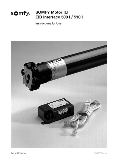
SOMFY Motor ILT<strong>EIB</strong> <strong>Interface</strong> <strong>500</strong> I / <strong>510</strong> IInstructions for UseRev. 02-05/2009 vm© by SOMFY Rottenburg
425SOMFY Motor ILTInstructions for UseAdvantages ofSOMFY Motor ILT:Final position adjustmentThe SOMFY Motor ILT is adjusted electronically throughan extra-low voltage control line. It is not necessary tomanually adjust the drive.==> Any necessary adjustments caused e. g. by a lengtheningor shortening of the roller shutter can bemade without opening the roller shutter box.Repeat accuracy of final positions==> SOMFY Motors are furnished with an exceptionallyhigh degree of repeat accuracy (± 2 %).Final position recognitionThe electronic final position recognition does not mechanicallystress the support material.==> Protects and prolongs the serviceable life of the rollershutter.Description ofSOMFY Motor ILTSOMFY Motors are composed of single-phase capacitormotors, brakes, gears and an electromechanical finalposition shutoff system.Important information that requires yourattention before installing the SOMFY Motor:CE conformity and interference suppressionSOMFY Motors conform with the following European guidelines:73/23/EEC and 89/336/EEC.SOMFY Motors in damp environmentsSOMFY drives are weather-proof protected in accordancewith EN 60529. Observe VDE regulations, e. g. 0100,Sections 701, 702 and 737 as well as obligatory regulationsand guidelines issued by local power suppliers andinspection authorities.Immobilisation detectionSOMFY Motors are equipped with an integrated immobilizationdetection system that monitors the upwards movementsof the roller shutters. The drive stops immediately.==> Protects the support material, e. g. when roller shuttersare blocked by ice.Obstacle detection in conjunction with a trip-free dog(accessory)The obstacle detection system monitors the downwardmovement of the roller shutter and recognises a blockedshutter.==> The drive stops immediately and automatically providesclearance for the removal of the obstacle.1. Shaft Pre-AssemblyPrefabricated spindlesSlide the drive together with the suitable spindle adapter(1) and dog (2) into the spindle.Precision tubes1Unlatch the spindle on the drive end. Slide drive into thespindle so that the adapter cam fits into the jog.2Warning! Slide drive into the spindle. Neveruse a hammer or force of any kind!3© by SOMFY Rottenburg
SOMFY Motor ILTInstructions for Use1.1 Riveting dog to precision tube spindles● Adjust distance between dog and drive pursuant to L 2(see table under 1.2) and rivet or screw dog with 4rivets or screws.Self-tapping screws: 4 screws (5 x 10 mm)Blind rivets: 4 steel rivets (Ø 5 mm steel)1.2 Drive typesL 1L 2L 3Drive type L 1 L 2 L 3ILT Jet 8/17 613 590 605ILT Ceres 10/17 613 590 605ILT Atlas 15/17 613 590 605ILT Meteor 20/17 663 640 655ILT Apollo 30/17 663 640 655ILT Mariner 40/17 753 730 7452.1 Final position adjustment with control box● Ensure that the drive is properly and duly connected toa 230 VAC mains supply.Important:1. The installation, testing and commissioningof 230 V installations must be carriedout by qualified electricians or electricaltechnicians. Observe ISO standards, especiallyDIN-VDE standards, and ensure that theelectrician/electrical technician has receivedthe installation instructions for each drive.2. Before activating the 230 VAC power supply,plug in and screw down the connector tothe drive.● Connect the western connector on one end of the controlline to the control box.Programming buttonsB C DA2. Adjustment Instructions forSOMFY Motor ILTUse the control box to adjust the final positions of theMotors. Manual adjustment is not necessary.Each Motor comes equipped with two brought out lines: a3-conductor cable for supply voltage and a 4-conductorcontrol line.RJ 45connectorLEDWhen control line and control box are properly connectedand the power supply has been activated the red LED onthe control box flashes quickly.2.2 Upper final position adjustment● ch Motor comes equipped with two brought out lines: a3-cond● Raise roller shutter with the UP button (B) to the desiredposition.● When upper final position is reached, release theUP button (B).conductorcontrol lineSELV = 5 VImportant:Do not raise shutter tomechanical limit.2-3 cm clearance isrequired!power supply ~230 Vearth = gr/yephase = brneutral = bl4© by SOMFY Rottenburg
SOMFY Motor ILTInstructions for Use2.2.1 Change of directionShould the roller shutter not move in the desired direction,e. g. upwards after pressing the UP button, press andhold the STOP button for approximately 2 seconds.2.3 Lower final positionadjustment● Set slide switch (A) to the positionfor adjusting the lower finalposition.● Lower roller shutter with theDOWN button (D) to the desiredposition.● When lower final position is reached, release theDOWN button (D).Important:It is possible to correct final position settingsby simply repeating the above procedures.2.4 User setting (intermediate position)2.4.2 Initiating user settingThe user setting can be initiated when the roller shutter isstopped in any position by pressing the STOP button (C).3. Western Connector PinAssignment and AttachmentUP (red)PE (blue)+5 V DC (white)DOWN (yellow)3.1 Control line pin assignment (plan view)Depending on the cable type the conductors may also becolour-coded as follows: black, red, green, yellow.3.2 Attaching western connectorsUse a pair of crimping pliers to strip and shorten a controlThe Motor allows you to program the roller shutter with auser setting. This means that in addition to the upper andlower final positions you have a user-programmable intermediateposition where the roller shutter automaticallystops when you press the STOP button and the drive isnot running.2.4.1 Programming user setting with control boxSet slide switch (A) on the control box to the middle position.Your control box now functions like a standardremote control.Press the DOWN button (D) and the roller shutter travelsto the lower final position and automatically stops.redbluewhiteyellowcolour markingcontrol line cableredbluewhiteyellowPress the UP button (B) and the roller shutter travels tothe upper final position and automatically stops.To stop the roller shutter simply press the STOP button(C).● Stop the roller shutter at the desired user settingposition.● When the roller shutter has fully stopped at that position,press and hold the STOP button (C) for 5seconds.line cable and to attach a western connector.Important:Ensure that the western connectors are mountedinversely to each other. Otherwise the pin assignmentof the connectors will nolonger correspond properly (use colour marking onthe control line for orientation).The user setting has now been saved.5© by SOMFY Rottenburg
SOMFY Motor ILTInstructions for Use4. Safety Systems„Right“ trip-free dog4.1 Trip-free dogThe SOMFY Motor ILT together with the SOMFY trip-freedog is equipped with an obstacle recognition system. Ifthe roller shutter run into an obstacle, the drive stopsautomatically and clearance is provided to remove theobstacle.Depending on the structure of the support material,observe that a „right“ or „left“ version of the trip-free dogis required.„Left“ trip-free dogPlease note:Trip-free dogs and the anti-intrusion system can only beused together with an <strong>EIB</strong> <strong>Interface</strong> <strong>510</strong> I in a roller shuttersystem.LT 50 trip-free dog (reinforced) List No.Left trip-free dog 9706003Right trip-free gog 97060046© by SOMFY Rottenburg
SOMFY Motor ILTInstructions for Use5. Technical DataILT Jet8/17ILT Ceres10/17ILT Atlas15/17ILT Meteor20/17ILT Apollo30/17ILT Mariner40/17Safety classIP protection classificationRated torqueRated rotational speedRated voltageRated outputCurrent consumptionFrequencyRated consumptionPick-up timeUltimate interruptioncapacityBase adapterfor 50 mm spindleDuty type as per VDE 0530Product standardConformityIIIP 448 Nm 10 Nm 15 Nm 20 Nm 30 Nm 40 Nm17 rpm~230 VAC (207 V – 244 V)90 W 120 W 140 W 160 W 240 W 270 W0,45 A 0,5 A 0,65 A 0,75 A 1,1 A 1,2 A50 Hz90 W 120 W 140 W 160 W 240 W 270 W4 min.300 rotations50 x 1.5 mmintermittent operation tr = 40% / make-up time tB = 4 min.VDE 0700 Section 238CE pursuant to EN <strong>500</strong>81-1 und EN <strong>500</strong>82-1Control lineControl line type AWG26 (4 x 0.12 mm 2 )Connector type western connector Typ RJ9 4/4Recommended max lenghtbetween motor and control1,5 m8© by SOMFY Rottenburg
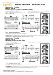
<strong>EIB</strong>-<strong>Interface</strong> <strong>500</strong> I/<strong>510</strong> IInstructions for Use6. <strong>EIB</strong>-<strong>Interface</strong> <strong>500</strong> I/<strong>510</strong> I6.1 Safety6.2 DescriptionThe installation, testing and commissioning of<strong>EIB</strong>s and <strong>EIB</strong> bus devices must be carried outby qualified electricians or electrical technicians.Observe ISO standards, especially DIN-VDE standards, as well as the installationinstructions in the ZVEI/ZVEH* <strong>EIB</strong>-Manualwhen laying and connecting leads andcables for bus and peripheral devices.6.3 InstallationBefore installing the <strong>EIB</strong> interface and theMotor, ensure that the drive’s 230 VAC mainsconnection cable is disconnected from the <strong>EIB</strong>interface terminals.The <strong>EIB</strong> interface can be surface or flush-mounted.Flush-mountingWe recommend the use of a flush mounting box 107 x107 x 57 mm (e. g. Kaiser). Remove the mounting eyelets(1) and insert the <strong>EIB</strong> interface into the flush-mountingbox.IP 205V / 29V1 2 3 4 56.4 Connection1 mounting eyelet 4 programming LED2 <strong>EIB</strong> bus terminal 5 programming button3a terminals 1-5, 6 terminal for control lineconnection-sideMotor3b terminals 1-5,(western socket)screw-clamp-sideSet terminals 1-5 (3) only potential-free!Pin assignment:• bus terminal (2):• terminals (3) 1-3:• terminals (3) 4+5:• western socket (6):bus cable conductorslocal switchwindow contactMotor control line9© by SOMFY Rottenburg
<strong>EIB</strong>-<strong>Interface</strong> <strong>500</strong> I/<strong>510</strong> IInstructions for Use6.5 CommissioningOperate <strong>EIB</strong> interface in accordancewith the specific technical data!To program the physical address, press the programmingbutton (5). Programming LED (4) illuminates.Recommendation: Use a screwdriver (see illustration) toaccess the programming button (5).Prior to commissioning your <strong>EIB</strong> interface, program thephysical address, group address, parameters and userapplication in the ETS. You will find the necessary <strong>EIB</strong>actuator product data in the product data base in the productfamily directory „roller shutters“ and the producttype „Motor“.The <strong>EIB</strong> interface is programmed through the ETS whilecommissioning by simply applying bus voltage to the system.230V operating voltage is not necessary for programming.<strong>EIB</strong> <strong>Interface</strong> <strong>500</strong> I Communication ObjectsNo. Name Function Description0 roller shutter position show 0 - 100 % Indicates actual roller shutter position. The shutter positioncan either be communicated to the bus periodicallyor when the shutter stops after moving.1 obstacle recognition UP show YES / NO Indicates an obstacle (e. g. frozen shutter) while the rollershutter is moving upwards (together with a SOMFYtrip-free). An obstacle triggers the transmission of „1“,the signal can be displayed through a suitable actuator(display, binary output).2 obstacle recognition show YES / NO Indicates an obstacle while the roller shutter is movingDOWNdownwards (together with a SOMFY trip-free).An obstacle triggers the transmission of „1“.3 window contact status show open / closed Indicates the actual status of the window contact. If thewindow parameter „window contact (external/local)“ isset to „local“, all Motor movements can be stopped via alocal window contact. If the window is open, a „1“ istransmitted and the Motor is automatically disabled. Ifthe window is closed, a „0“ is transmitted and the Motoris re-enabled.4 move command UP / DOWN A message to this object causes the drive to actuate.„0“ = upper final position, „1“ = lower final position.5 STOP command STOP A message to this object causes the drive to stop.10© by SOMFY Rottenburg
<strong>EIB</strong>-<strong>Interface</strong> <strong>500</strong> I/<strong>510</strong> IInstructions for UseNr. Name Function Description6 inhibit move commands YES / NO If the window parameter „window contact(external/local)“ is set to „external“, all Motor movementscan be stopped via a local window contact. A „1“stops the Motor automatically, a „0“ re-enables theMotor.7 safety priority command A „1“ generates a move command to the programmablesafety position (upper or lower final position). The systemis deactivated until a „0“ re-enables the system. Ifthe parameter „receive safety signal (static/cyclic)“ is setto „cyclic“, the system can only operate if a „0“ is receivedperiodically. If the required „0“ is not received withinthe specific period of time, the drive automatically moveto the safety position.8 user setting move / save Drive moves to programmed user setting OR saves theactual position as the user setting when the systemreceives a message from this object. The value in thereceived message is not important. The actual value ofobject no. 9 (ìuser setting modeî) determines whichfunction is performed.9 user setting mode save ON / OFF Selection of function for object no. 8. A moving command(i.e. object value = „0“) moves the drive to usersetting if object no. 8 is engaged. If the save mode isenabled (i.e. object value = „1“), the drive saves theactual roller shutter position as the new user setting, ifobject no. 8 is engaged.10 sunshade position move Drive moves to programmed sun position if a „1“ isreceived and the roller shutter is above the sun position.The sun position is set during initial installation. A „0“moves the drive either to the upper final position or thedrive ignores the command.11© by SOMFY Rottenburg
<strong>EIB</strong>-<strong>Interface</strong> <strong>500</strong> I/<strong>510</strong> IInstructions for Use<strong>EIB</strong> <strong>Interface</strong> <strong>500</strong> I Parameter Descriptions(Factory settings are in italics!)Parameter Settings Description❐ Safetysafety position upper final position Drive moves to upper final position.lower final position Drive moves to lower final positionreceive safety message static Drive moves to programmed safety position when noncyclicallytransmitted safety message is not received.cyclicDrive moves to programmed safety position whencyclically transmitted safety message is received.safety monitor cycles 14 Monitoring period for receiving cyclic safety message.in 5 sec. [1..63]The monitoring time must be greater than the cyclicperiod of the transmitting element.❐ Window contactwindow contact external Drive disabled through message to Object no. 8.localLocally connected window contact disables drive.window contact NO contact Disenabled by opening contact.NO contactDisenabled by closing contact.window contact: transmit value YES The actual window status indicated through objectno. 3.NOWindow status not indicated.❐ Roller shuttersend roller shutter position YES Actual roller shutter position is transmitted(0% - 100%).NORoller shutter position is not transmitted.send periodically YES Roller shutter position updated every second.NORoller shutter position updated when drive stops.❐ Sunshade positionsun position (0% - 100%) 80% A „1“ moves the drive to the programmed sun position.open YES A „0“ move the drive from the programmed sun positionto the upper final position.NOThe drive remains in the sun position.❐ Obstacle recognitionalarm YES Alarm signal issued if an upward movement obstacleupward movement obstacleis detected.NONo alarm signal if an upward movement obstacleis detected.alarm YES Alarm signal issued if a downward movement obstacledownward movement obstacleis detected.NONo alarm signal if a downward movement obstacle isdetected.12© by SOMFY Rottenburg
<strong>EIB</strong>-<strong>Interface</strong> <strong>500</strong> I/<strong>510</strong> IInstructions for Use<strong>EIB</strong> <strong>Interface</strong> <strong>510</strong> I Communication ObjectsNo. Name Function Description0 roller shutter position show 0% - 100% Indication of actual roller shutter position in %. The positioncan be communicated to the bus periodically oronly after the roller shutter has come to a complete stop.1 lower final position show YES / NO Indication of lower final position. When the drive reachesthe lower final position, a „1“ is transmitted. When thedrive leaves that position, a „0“ is transmitted.2 upper final position show YES / NO Indication of upper final position. When the drive reachesthe upper final position, a „1“ is transmitted. Whenthe drive leaves that position, a „0“ is transmitted.3 window contact status show open / closed Indicates the actual status of the window contact. If thewindow parameter „window contact (external/local)“ isset to „local“, all Motor movements can be stopped via alocal window contact. A „1“ commands the Motor toautomatically move to the disabled position (upper orlower final position, STOP or no move command). Furtherdrive commands are ignored. A „0“ re-enables theMotor system.4 obstacle recognition show YES / NO Indicates an obstacle (e. g. frozen shutter) while the rollershutter is moving upwards or downwards (togetherwith a SOMFY trip-free). An obstacle triggers the transmissionof „1“ and disables the drive. A „0“ re-enablesthe drive.5 alarm show YES / NO If the closed roller shutter is opened without a movingcommand (e. g. intrusion), a „1“ is transmitted. Thealarm signal is reset with „0“. The alarm signal is onlyactive at 85% - 100%.13© by SOMFY Rottenburg
<strong>EIB</strong>-<strong>Interface</strong> <strong>500</strong> I/<strong>510</strong> IInstructions for UseNo. Name Function Description6 move command UP / DOWN A „0“ message commands the drive to move to theupper final position, a „1“ message to the lower finalposition.7 STOP command STOP A message to this object causes the drive to stop.8 disable move command YES / NO If the window parameter „window contact(external/local)“ is set to „external“, all Motor movementscan be stopped through this object. A „1“ commandsthe Motor to automatically move to the disabledposition (upper or lower final position, STOP or no movecommand). Further drive commands are ignored. A „0“re-enables the Motor system.9 safety priority command A „1“ generates a move command to the programmablesafety position (upper or lower final position). The Motorsystem is deactivated until a „0“ re-enables the system.10 move roller shutter move 0-100% The roller shutter can be moved to any position withposition a 1 byte message (0% - 100%).<strong>EIB</strong> <strong>Interface</strong> <strong>510</strong> I Parameter Description(Factory settings are in italics)Parameter Settings Description❐ Safetysafety position upper final position The drive moves to the upper final position.lower final position The drive moves to the lower final position.STOPThe drive stops.no move command The drive moves up or down when this command isissued. Any further commands are blocked.receive safety signal static The drive moves to the programmed safety position if anon-cyclic safety message is received.cyclicThe drive moves to the programmed safety position if acyclic safety message is received.safety monitoring cycle 14 Überwachungszeitraum zum Empfang eines zyklischenin 5 seconds [1..63]Sicherheitstelegrammes. Die Überwachungszeit mußgrößer eingestellt werden, als die Zykluszeit des sendendenTeilnehmers.14© by SOMFY Rottenburg
<strong>EIB</strong>-<strong>Interface</strong> <strong>500</strong> I/<strong>510</strong> IInstructions for UseParameter Setting Description❐ Window contactwindow contact extern Drive is disabled with a message to object no. 8. Thelocally connected window contact disables the drive.localOpening the contact disables the drive.window contact NC contact Closing the contact disables the drive.NO contactDurch Schließen des Kontaktes wird der Antriebgesperrt.window contact: send value YES The actual window contact status is indicatedthrough object no. 3NOThe actual window contact status is notindicated.blocking position upper final position The drive moves to the upper final position.lower final position The drive moves to the lower final position.STOPThe drive stops.no move command The drive moves up or down when this commandis issued. Any further commands areblocked.❐ Roller shuttersend roller shutter position YES The actual roller shutter position is transmitted(0% - 100%).NOThe roller shutter position is not transmitted.send periodically YES The updated roller shutter position is transmittedevery second.NOThe roller shutter position is transmitted afterdrive has come to a complete stop.❐ Sunshade positionalarm YES Alarm signal is issued if a upward/downwardmovement obstacle is detected.NONo obstacle alarm signal is issued.15© by SOMFY Rottenburg
SOMFY Motor ILT<strong>EIB</strong>-<strong>Interface</strong> <strong>500</strong> I/<strong>510</strong> IInstructions for Use6.6 Technical data / terminal connection plan<strong>EIB</strong>-<strong>Interface</strong> <strong>500</strong> I List No.: 1860020<strong>EIB</strong>-<strong>Interface</strong> <strong>510</strong> I List No.: 1860021Dimensions85 x 45 x 26 mm<strong>EIB</strong> bus currentconsumption< 10 mA DCIP rating IP 20Ambient conditions clean environment indoorOperating temp. range 0° – +45°CStorage temperature -20 – +70°CrangeRecommanded max. lengthlocal switch10 mRecommanded max. lengthwindow contact10 mRecommanded max. lengthControl motor1,5 mRecommend cable type forcontrol line I-Y(St)Y 2 x 2 x 0.8recommend cable type forcontrol line of drive AWG 26 (4 x 0.12 mm 2 )Compliance with EMC- guidelines in accordanceguidelineswith <strong>EIB</strong> Manual Version2.21-conformity EN 60730DIN EN <strong>500</strong>81-1(emitted interference)DIN EN <strong>500</strong>82-1( interference immunity)All rights reserved to alter specifications without prior notice SOMFY SAS, capital 20.000.000 euros, RCS Bonneville303.970.230 © SOMFY / COM ref COM020229In Germany:Feinmechanik und Elektrotechnik GmbHFelix-Wankel-Straße 50 . D-72108 Rottenburg/NeckarPostfach 186 . D-72103 Rottenburg/NeckarTelefon (0 74 72) 930-0 . Telefax (0 74 72) 930-9Internet: http://www.somfy.deIn Austria:SOMFY Feinmechanik und Elektrotechnik GmbHJohann-Herbst-Straße 23 . A-5061 Elsbethen-GlasenbachTelefon ++43 (0)662 62 53 08 . Telefax ++43 (0)662 62 53 08 22Internet: http://www.somfy.at