SERVISNA NAVODILA ZA BTV S ŠASIJO E9 - Reptips
SERVISNA NAVODILA ZA BTV S ŠASIJO E9 - Reptips
SERVISNA NAVODILA ZA BTV S ŠASIJO E9 - Reptips

You also want an ePaper? Increase the reach of your titles
YUMPU automatically turns print PDFs into web optimized ePapers that Google loves.
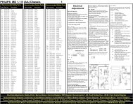
Chassis <strong>E9</strong>-service manual<br />
V/2000 436551<br />
CHASSIS <strong>E9</strong><br />
SERVICE MANUAL<br />
Page<br />
• TECHNICAL SPECIFICATIONS TV SETS WITS CHASSIS <strong>E9</strong>…………….…………2<br />
• MODULES ARRANGEMENT ON CHASSIS……..……..……..……..……..…………….4<br />
• GENERAL INSTRUCTIONS……..……..……..…………...……..……..…5<br />
X-RAY RADIATION……..……..……..……..……..……..……..……..…………………………5<br />
SAFETY……..……..……..……..……..……..……..…………….……..……..……..……..……..5<br />
MEASUREMENT CONDITIONS……..……..……..……..……..……..……..……..………….....6<br />
• BLOCK DIAGRAM AND OPTIONS TABLES……..……..……..……..……..…………..7<br />
• BLOCK DIAGRAM – CONTROL SIGNALS……..……..……….…..……..……..8<br />
• BLOCK DIAGRAM - SUPPLY VOLTAGES……..……..……..……..……..……………..9<br />
• SERVICE ADJUSTMENTS OF THE COLOUR TV WITH <strong>E9</strong> CHASSIS………….....10<br />
• ELECTRICAL DIAGRAM OF MAIN CHASSIS <strong>E9</strong>……..……..……..……..…………..23<br />
• ELECTRICAL DIAGRAM OF MODULES FOR CHASSIS <strong>E9</strong>……..……..……….…..24<br />
• OSCILLOGRAMS……..……..……..……..……..……..……..……..……..……..………..25<br />
• MAIN CHASSIS - COMPONENT SIDE……..……..……..……..………..……..……..…26<br />
• ELECTRICAL DIAGRAMS OF SEPARATE MODULES FOR CHASSIS <strong>E9</strong>……....27<br />
• COMPONENT LOCATIONS ON SEPARATE MODULES OF CHASSIS <strong>E9</strong> –<br />
COMPONENT SIDE ……..……..……..……..……..……..……..……..……..……..……29<br />
• LIST OF RECOMMENDED SPARE PARTS FOR CHASSIS AND MODULES …….34<br />
1
Chassis <strong>E9</strong>-service manual<br />
<strong>E9</strong> CHASSIS - TECHNICAL SPECIFICATION – Rev.11<br />
TVTEXT Version 1p TVTEXT Version 7p (SDA TVTEXT Version Dolby 7p<br />
(SDA5252-2)<br />
5255-2)<br />
(OTP)<br />
1. SCREEN 90° or 110°,<br />
90° or 110°,<br />
90° or 110°,<br />
SIZE:<br />
14”,20”,21”, 25”, 28”, 33” 21”, 25”, 28”, 33” (4:3),<br />
21”, 25”, 28”, 33” (4:3),<br />
(4:3).<br />
28”, 32” (16:9).<br />
28”, 32” (16:9).<br />
2. AVAILABLE • PAL BG,<br />
• PAL BG,<br />
• PAL BG,<br />
STANDARDS: • PAL I,H (opt.),<br />
• PAL I,H (opt.),<br />
• PAL I,H (opt.),<br />
• PAL/SECAM BG (opt.), • PAL/SECAM BG (opt.), • PAL/SECAM BG (opt.),<br />
• PAL/SECAM BG / DK • PAL/SECAM BG / DK (opt.), • PAL/SECAM BG / DK (opt.),<br />
(opt.),<br />
• NTSC through SCART (opt.), • NTSC through SCART (opt.),<br />
• NTSC through SCART<br />
(opt.),<br />
• SECAM L/L' (opt.).<br />
• SECAM L/L' (opt.).<br />
• SECAM L/L' (opt.).<br />
3. TUNER: HYPERBAND: VHF 2-12, HYPERBAND: VHF 2-12, HYPERBAND: VHF 2-12,<br />
UHF 21-69, S1-S41<br />
UHF 21-69, S1-S41<br />
UHF 21-69, S1-S41<br />
4. FEATURES: Frequency synt. (125KHz Frequency synt. (125KHz search Frequency synt. (125KHz search<br />
search steps),<br />
steps),<br />
steps),<br />
MENU oriented OSD (On MENU oriented OSD (On Screen MENU oriented OSD (On Screen<br />
Screen Disp.)<br />
Disp.) Multilanguage MENU OSD, Disp.)<br />
100 programs,<br />
100 programs,<br />
Multilanguage MENU OSD,<br />
Full function remote control, Full function remote control, 100 programs,<br />
Automatic switch off at the Automatic switch off at the end of Full function remote control,<br />
end of the progr.<br />
the progr.<br />
Automatic switch off at the end of<br />
Off timer 0 - 120 min., Off timer 0 - 120 min.,<br />
the program<br />
Organise Program<br />
Organise Program Information Off timer 0 - 120 min.,<br />
Information System (OPIS) System (OPIS) with the following Organise Program Information<br />
with the following functions: functions:<br />
System (OPIS) with the following<br />
• Autostore<br />
• Autostore with simple ATS: functions:<br />
• Insert<br />
Autostore, Name, Order, • Autostore with simple ATS:<br />
• Delete<br />
• Insert<br />
Autostore, Name, Order,<br />
• Rename,<br />
• Delete<br />
• Insert<br />
Hotel mode (opt.).<br />
• Rename,<br />
• Delete<br />
Copy funct. SCART2 to SCART1 • Rename,<br />
(opt.),<br />
Copy function SCART2 to SCART1<br />
Hotel mode (opt).<br />
(opt.),<br />
Hotel mode (opt.).<br />
5. SOUND: MONO/STEREO/DUAL MONO/STEREO/DUAL sound Dolby Surround Pro-Logic sound ,<br />
sound decoder,<br />
decoder,<br />
MONO/STEREO/DUAL sound<br />
Digital Stereo Sound Digital Stereo Sound Processor, decoder,<br />
Processor,<br />
Muting,<br />
Digital Stereo Sound Processor,<br />
Muting,<br />
1 or 2 loudspeakers,<br />
Muting,<br />
1 or 2 loudspeakers Audio music power:<br />
2 loudspeakers,<br />
(STEREO),<br />
1x15W (MONO),<br />
Additional 2 tweeter speakers<br />
Audio music power output: 2x15W (STEREO),<br />
(opt.),<br />
1x15W (MONO),<br />
Additional 2 tweeter loudspeakers Built in additional Subwoofer<br />
2x15W (STEREO), (opt.),<br />
loudspeaker (Cabinet opt.),<br />
STEREO through SCART Built in additional Subwoofer Audio music power: 60W<br />
(opt.),<br />
loudspeaker with 30W music (15W Left, 15W Right 15W Centre,<br />
German STEREO + NICAM power (Cabinet opt.),<br />
15W Surround)<br />
(opt.),<br />
STEREO through SCART (opt.), German STEREO + NICAM (opt.),<br />
German STEREO + NICAM Automatic volume levelling (opt),<br />
(opt.),<br />
Separate volume adj. on<br />
Automatic volume levelling<br />
(opt.),<br />
Headphones.<br />
2
Chassis <strong>E9</strong>-service manual<br />
TVTEXT Version 1p<br />
(SDA5252-2)<br />
6. TELETEXT: 1 - page TTX with P26,<br />
Westeuropean and<br />
easteuropean language<br />
support.<br />
7.<br />
SCART I AV connector<br />
CONNECTIONS: (21 - pin)<br />
video,<br />
RGB,<br />
SVHS,<br />
HeadPhones Socket (opt.),<br />
Antenna connection 75<br />
ohms unbalanced.<br />
8. ADDITIONAL<br />
OPTIONS<br />
1TPIP - 1 tuner picture in<br />
picture (opt.),<br />
9.VIDEO: Black and Blue stretch,<br />
Blue back when no video,<br />
Automatic Colour limiting,<br />
CTI (opt.),<br />
ZOOM.<br />
10.<br />
CONSUMPTION:<br />
24.12.1999<br />
≈65W for 90°<br />
≈95W for 110°<br />
POWER REQUIREMENTS:<br />
Voltage/frequency:<br />
230V/50Hz<br />
rating (180V -<br />
250V)<br />
Separate volume adj. on Headph.s<br />
(opt.).<br />
TVTEXT Version 7p (SDA TVTEXT Version Dolby 7p<br />
5255-2)<br />
(OTP)<br />
7 - page TTX with the TOP (opt.), 7 - page TTX with the TOP (opt.),<br />
FLOF and P26,<br />
FLOF and P26,<br />
Westeuropean and easteuropean Westeuropean and easteuropean<br />
language support.<br />
language support.<br />
SCART I AV connector (21 - pin) SCART I AV connector (21 - pin)<br />
video, RGB and SVHS,<br />
video, RGB and SVHS,<br />
HeadPhones Socket (opt.), HeadPhones Socket (opt.),<br />
SCART II (opt.),<br />
SCART II (opt.),<br />
MINI DIN SVHS connector with External speakers connectors (Front<br />
chinch AV inputs (opt.), front or L and R, Rear L and R<br />
backside AV - cabinet dependent, MINI DIN SVHS connector with AV<br />
External speakers connectors chinch inputs (opt.), front or<br />
(opt.),<br />
backside AV - cabinet dependent,<br />
Antenna connection 75 ohms Antenna connection 75 ohms<br />
unbalanced,<br />
unbalanced.<br />
1TPIP - 1 tuner picture in picture<br />
(opt.),<br />
2TPIP - 2 tuner picture in picture<br />
(opt.) with the sound on the<br />
headphones from 2 nd 1TPIP - 1 tuner picture in picture<br />
(opt.),<br />
2TPIP - 2 tuner picture in picture<br />
(opt.) with the sound on the<br />
tuner source. headphones from 2 nd tuner source.<br />
Black and Blue stretch,<br />
Black and Blue stretch,<br />
Blue back when no video, Blue back when no video,<br />
Automatic Colour limiting, Automatic Colour limiting,<br />
Colour Temperature adjustment, Colour Temperature adjustment,<br />
CTI (opt.),<br />
CTI (opt.),<br />
ZOOM (4:3),<br />
ZOOM (4:3),<br />
Linear picture zoom (16:9). Linear picture zoom (16:9).<br />
≈65W for 90°<br />
≈65W for 90°<br />
≈95W for 110°<br />
≈95W for 110°<br />
POWER REQUIREMENTS: POWER REQUIREMENTS:<br />
Voltage/frequency: 230V/50Hz Voltage/frequency: 230V/50Hz<br />
rating (180V - 250V)<br />
Rating (180V - 250V)<br />
3
MODULES ARRANGEMENT ON CHASSIS<br />
12.12.1999<br />
4
Chassis <strong>E9</strong>-service manual<br />
GENERAL INSTRUCTIONS<br />
X-RAY RADIATION<br />
Picture tube is potential source of X-radiation of colour TV. Use exclusively original types of<br />
replacement picture tubes, specified in technical documentation. Accelerating high voltage must not<br />
exceed 30 kV. Supply voltage "B+" for horizontal output stage must be set according to the<br />
specifications given in service manual.<br />
SAFETY INSTRUCTIONS<br />
Service interventions on colour TV can be performed by authorised and qualified personnel only,<br />
considering the following instructions:<br />
• During service interventions connect the TV set to mains voltage through separating (isolating)<br />
transformer.<br />
• During servicing procedures (replacement of individual components) disconnect the cord from mains<br />
connector.<br />
• After disconnection and before servicing wait about 30 sec. so that charged electrolytes and picture<br />
tube are discharged.<br />
• Provide for additional discharge of picture tube when replacing it and use protective means to<br />
prevent injuries due to eventually broken glass.<br />
• When changing modules or complete chassis, fix it with adequate elements (screws, latches, ...).<br />
• Wires inside the TV set should not come in contact with sharp or hot areas.<br />
• Integrated circuits and other semiconductors on chassis are sensitive to overvoltages and high<br />
temperatures.<br />
During service interventions they should be protected against too long heating with soldering iron (5<br />
sec.), electrostatic discharges, short circuits between connectors etc. Therefore the following general<br />
instructions should be followed:<br />
• Use low impedance disconnecting transformer for connection of chassis to mains voltage.<br />
• Use low voltage soldering irons with protective earthing.<br />
• Chassis earthing should be equal to earthing of measuring and calibrating equipment and tools.<br />
• When connecting instruments, first connect negative connector (mass, earth) and afterwards signal<br />
connector.<br />
• Voltages to be checked should be measured with suitable instruments. Do not use "short-circuit<br />
methods" with pincets or screwdriver.<br />
• Conductors under high voltage should not be placed near semiconductors on chassis.<br />
• Installed IC’s, transistors and MOSFET’s are made in various semiconductor technologies (CMOS,<br />
MOS, BIMOS or bipolar technology) and are more or less sensitive to exterior effects during<br />
handling. All these elements should be handled in accordance with the requirements for<br />
electrostatic protection. If these requirements are fulfilled, you prevent formation of undesired<br />
electrostatic discharges which can destruct semiconductors or can activate destructive mechanisms,<br />
which destroy circuit during operation.<br />
Accumulated electrostatic charge is discharged through individual connectors of IC or transistor during<br />
electrostatic discharges and current runs through semiconductor structure. Considering that thicknesses<br />
of semiconductor substrate, used for IC, are very small, this current can cause damages to IC or destroy<br />
it. For the protection of circuits the currents originating from discharges should be discharged under<br />
control. This is obtained in the following ways:<br />
• Staff handling the ICs should have earthed hands by means of a suitable wire and resistor.<br />
• Working table should as well be earthed. Working surface should be made of conducting material<br />
(conducting rubber), soldering irons and all required equipment should be earthed.<br />
• Carrying and storing is permissible only in original packaging (antistatic tubes, conducting<br />
sponges).<br />
• If IC is mounted on a base, it should not be replaced under voltage.<br />
5
Chassis <strong>E9</strong>-service manual<br />
MEASUREMENT CONDITIONS<br />
• HF input signal in antenna: 1mV, with ″Philips″ test signal<br />
• Input video signal on SCART connector: 1 Vpp<br />
• Input audio signal on SCART connector: 500 mVeff<br />
• Brightness, contrast and colour of picture, volume of sound set to normal (near middle of scale)<br />
• Measure DC voltages with digital voltmeter with 1% precision<br />
• Measuring instrument (voltmeter or oscilloscope) connect to tuner ground during measuring on<br />
secondary side of mains (SMPS) transformer and on primary side during measuring on primary side<br />
SMPS supply circuit.<br />
6
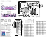
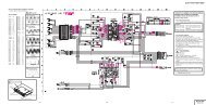
BLOCK DIAGRAM AND OPTIONS TABLES<br />
SOUN PROCESSOR TYPES<br />
TYPE SOUN STANDARD PCB<br />
TDA 3400 STEREO+AM(L/L')<br />
(till 2xscart)<br />
ST/E6-<strong>E9</strong><br />
TDA 3410D STREO+NICAM<br />
(more like 2xscart, 2 nd<br />
tuner)<br />
ST/E6-<strong>E9</strong><br />
TDA 3401 G STEREO+VIRT.<br />
DOLBY<br />
ST/E6-<strong>E9</strong><br />
TDA 3401 STEREO (till 2x<br />
scart)<br />
ST/<strong>E9</strong><br />
TDA 3415 STEREO+NICAM (till<br />
2xscart)<br />
ST/<strong>E9</strong><br />
S-VHS<br />
VIDEO<br />
AUDIO-L<br />
AUDIO-R<br />
230V AC<br />
SL1-<strong>E9</strong><br />
SAT-EU<br />
S1-IN<br />
K91<br />
K92A<br />
K92B<br />
K92C<br />
SFTL-<strong>E9</strong><br />
TP-CG<br />
TP-<strong>E9</strong><br />
K104B<br />
K104C<br />
(na poz. KD-E6)<br />
K-1201B K-1202B K1203B<br />
K508B<br />
K404A<br />
PR- PR+ + M<br />
PR- PR+ + M<br />
PR- PR+ + M<br />
HARDWARE OPTIONS FOR<br />
PROCESSORS (IC901)<br />
SCART 2 J910 J911<br />
ENABLE - �<br />
DISABLE � -<br />
SECAM L J902<br />
ENABLE -<br />
DISABLE �<br />
D/K J906<br />
ENABLE -<br />
DISABLE<br />
COPY OPTION (what is<br />
�<br />
on AV1, or from AV2 -><br />
to AV1)<br />
J905<br />
ENABLE -<br />
DISABLE �<br />
K104B<br />
K104C<br />
K901B<br />
K901B<br />
K901B<br />
L,R<br />
C,Y<br />
<strong>E9</strong><br />
K901B K901A<br />
KD-E6<br />
SVHS-<strong>E9</strong><br />
TUNER1<br />
FL2477/84<br />
TUNER2<br />
FL2477/84<br />
TDA9800<br />
K-1201B K-1202B K1203B<br />
K-1201A K-1202A K1203A<br />
K404B<br />
K403B<br />
K401B K402B<br />
K401A K402A<br />
EU-<strong>E9</strong><br />
IC1<br />
SDA5250<br />
IC901<br />
TDA8540<br />
SDA525X<br />
POWER SUPPLY<br />
TDA4605-2<br />
BUZ90A<br />
K1<br />
K2<br />
K3<br />
K4<br />
150V<br />
33V<br />
24V<br />
12V<br />
8V<br />
5VA<br />
5V<br />
15VT<br />
7p<br />
only<br />
1p/7p<br />
7p<br />
only<br />
SAW<br />
filter<br />
IC902<br />
IC903<br />
K902A<br />
OC-<strong>E9</strong><br />
a b<br />
a b<br />
R-626<br />
TUNER SELECTION*:<br />
TUNER SELECTION J901 J912<br />
SIEL - -<br />
ALPS � -<br />
TEMIC and SELTEKA - �<br />
TEMIC and SELTEKA � �<br />
*except SDA5255 A052 - only SIEL<br />
SIGNAL & DEFL.<br />
PROCESSOR SEL.<br />
TDA8840 90° PAL<br />
TDA8842 90° PAL/SECAM<br />
TDA8843 110° PAL<br />
TDA8844 110° PAL/SECAM<br />
TDA884X<br />
SIGNAL AND<br />
DEFL.<br />
PROCESSOR<br />
CVBS_ext<br />
VIDEO<br />
SWITCH<br />
TEA2014<br />
CVBS_SC2<br />
K106A<br />
STEREO: ST-<strong>E9</strong>,ST-E6/9<br />
DOLBY: STD-<strong>E9</strong><br />
MONO: /<br />
MSP34XX<br />
TDA2545A<br />
DPL3519A<br />
K506A<br />
K507<br />
K508A<br />
K510A<br />
K500B, K501B, K502B, K503B, K504B<br />
K500A, K501A, K502A, K503A, K504A<br />
CVBS int<br />
CVBS_SC1<br />
SCART 2<br />
PIP-<strong>E9</strong><br />
SAA9288<br />
TDA8310<br />
L,R<br />
K001C<br />
K806B<br />
K800B,K801B,K802B,K803B,K804B,K805B<br />
K800A,K801A,K802A,K803A,K804A,K805A<br />
K105A<br />
SCART 1<br />
PROCESSOR & EEPROM SELECTION<br />
IC901<br />
Text<br />
pages<br />
SDA5252-2 B001 EV <strong>E9</strong> 1P 17 99 1p 24C08 / /<br />
SDA5255 B002 EV <strong>E9</strong> 1P 19 99 1p 24C08 / /<br />
SDA5255 A052 7p<br />
SDA5255-2 B001 EV <strong>E9</strong> 7P 27 99 7p 24C16 / up to 1<br />
SDA5255 B003 EV <strong>E9</strong> 7P 29 99 7p<br />
or<br />
Piggy back with SDA 5250 7p 24C08AT 24C32 up to 4<br />
SDA545x OTP 1p/7p<br />
IC902 IC903 Optional no.<br />
languaes<br />
���������������������������� �����<br />
�����<br />
����������������������������<br />
���������������������������� �����<br />
APD-<strong>E9</strong><br />
K1301<br />
����������������������������<br />
�����<br />
����������������������������<br />
���������������������������� �����<br />
TDA2616A<br />
���<br />
�������������������������<br />
����������������������������<br />
AP-<strong>E9</strong><br />
K1301<br />
TDA2616<br />
NE5532<br />
AUDIO OUT<br />
TDA7057A<br />
V+<br />
V-<br />
GUARD<br />
VERT. OUT<br />
TDA8351 (110)<br />
TDA8356 (90)<br />
H.DRIVE<br />
EW DRIVE<br />
H. FLY<br />
EHT COMP<br />
LZZ-<strong>E9</strong><br />
K752<br />
���<br />
�������������������������<br />
����������������������������<br />
HOR. OUT<br />
BU508A (110)<br />
BU508D (90)<br />
K1303<br />
K74B<br />
K703A K704A<br />
�����<br />
�������� �����������������������������<br />
����������������������������<br />
����������������������������� �����<br />
K751<br />
K703B K704B<br />
���<br />
���������������������������<br />
���������������������������<br />
����������������������������<br />
K104A<br />
��������<br />
��������<br />
��������<br />
DOLBY PROLOGIC<br />
K104B<br />
R G B<br />
K102A K101B<br />
���������������������������������<br />
��������<br />
��<br />
��<br />
���������������������������������<br />
�����������������������������������<br />
SD1<br />
����<br />
����������������������������������<br />
���������������������������������� ����<br />
K73<br />
DZ1<br />
K72<br />
K71<br />
����<br />
����������������������������������<br />
���������������������������������� ����<br />
R<br />
L<br />
��<br />
����������������������������������<br />
���������������������������������<br />
�����������������������������������<br />
K74<br />
����<br />
������������������������������������<br />
������������������������������������<br />
���������������������������������� ����<br />
VK-<strong>E9</strong>: 4:3<br />
VK-<strong>E9</strong>T: 16:9<br />
VK-<strong>E9</strong>M: minineck<br />
TDA6107<br />
TDA6108<br />
Rext<br />
Lext<br />
SUB<br />
Rext<br />
Lext<br />
R<br />
G<br />
B<br />
������<br />
������������������������<br />
������������������������ ������<br />
SUR1<br />
K51<br />
MODULES VK IN PICTURE TUBES<br />
Picture tube Manufacturer<br />
VK-<strong>E9</strong> (4.3) basic for 90° in 110° pict. tubes<br />
A48EAX13X01 Thomson<br />
A48EEV13X01 Thomson<br />
A51EBV13X01 Thomson<br />
A51EAL30X01 Vista<br />
A51EAL155X01 Philips<br />
A51EJJ01X01 Ekranas<br />
VK-<strong>E9</strong>T (16:9) for 16:9 pict. tubes<br />
W66EHK50X06 Panasonic<br />
W66EHK51X26 Panasonic<br />
W76EGV23X115 Videocolor<br />
W76EGX23X115 Videocolor<br />
VK-<strong>E9</strong>T1 (16:9) for 16:9 pict. tubes<br />
W76ESF031X14 Philips<br />
VK-<strong>E9</strong>M (4:3) for minineck pict. tubes<br />
A48JAN43X02 BPL<br />
A51JAR70X05 BPL<br />
10.12.1999<br />
������<br />
������������������������<br />
������������������������ ������<br />
������<br />
��������������������������<br />
��������������������������<br />
������������������������ ������<br />
Cext<br />
SRext<br />
SLext<br />
7
Chassis <strong>E9</strong>-service manual<br />
BLOCK DIAGRAM – CONTROL SIGNALS<br />
8
Chassis <strong>E9</strong>-service manual<br />
BLOCK DIAGRAM - SUPPLY VOLTAGES<br />
9
Chassis <strong>E9</strong>-service manual<br />
SERVICE ADJUSTMENTS OF THE COLOUR TV WITH <strong>E9</strong> CHASSIS<br />
All necessary adjustments and settings are performed during manufacture of TV set and assure its<br />
correct operation when connected to the mains voltage and antenna or external video or audio signal.<br />
When TV set requires service intervention all settings should be checked and corrected, if necessary.<br />
DEMAGNETISING OF PICTURE TUBE<br />
Correctness of picture tube demagnetising is usually automatically checked. Magnetisation of picture<br />
tube is presented as one or more colour "clouds", consequently colour reproduction of the picture is<br />
not correct.<br />
Each time the TV set is switched on with mains switch, demagnetising system is activated. For correct<br />
demagnetising procedure disconnect the TV set with mains switch and leave it disconnected for about<br />
15 minutes. Afterwards when you switch on the TV, demagnetising procedure is performed. In case<br />
distortion of colour reproduction still persists, special demagnetising coil should be used.<br />
ADJUSTMENT ADJUSTMENT<br />
CONDITION<br />
1. SUPPLY VOLTAGE<br />
FOR HORIZONTAL<br />
OUTPT STAGE<br />
»B+«<br />
SWITCHING TO SERVICE MODE<br />
• Connect the TV set to<br />
supply voltage<br />
175…250VAC.<br />
• Switch it on and set it by<br />
means of remote<br />
controller to AV mode of<br />
operation.<br />
• Connect DC voltmeter to<br />
D-602 cathode.<br />
ADJUSTMENT ACTIVITY<br />
AND RESULT OF SETTINGS<br />
With P-601 potentiometer set supply voltage for<br />
horizontal output stage to:<br />
• 90° CTV: 118V ±0,2V<br />
• 110° CTV: 155V ±0,2V<br />
• 110°/16:9 CTV: 155V ±0,2V<br />
All other service settings of TV set are made in so called service mode of TV set operation. To enter this mode of operation press<br />
the keys in the following sequence: "TV", "I", and "STOP" in the period of 5 seconds from switching on the TV set to normal mode<br />
of operation. When the TV set is switched over to service mode the following status line with service parameter and parameter value<br />
appears on the screen:<br />
SERVICE PARAM: XX VALUE: xx<br />
The parameter to be set is selected with keys (P+/P-), and selected parameter is set with keys (volume+ /volume-). Each<br />
time you press the key for parameter selection ( ) the value of preselected parameter is stored. Therefore when the last setting is<br />
performed you must press one of the two keys once again. Values of individual parameters are expressed in hexadecimal form due<br />
to limited capacity of the memory. Values of individual parameters are variable from 0 to 3F, with the exception of parameters 11,<br />
12 and 13 where values are changed from 0 to 7F and O1, O2, O3, O4, which have value range between 0 and FF.<br />
When setting is finished it should obligatory be concluded with "STOP" key. After a few seconds the status line disappears and<br />
service adjustment is accomplished.<br />
NOTE: In case service adjustment is not ended in above specified mode (e.g. power supply breakdown), the<br />
adjustment should be repeated.<br />
2. VERTICAL • To antenna connector of • With remote<br />
PICTURE<br />
TV set, which is switched controller set vertical<br />
POSITION<br />
on and operates in service position of the<br />
mode, connect VF signal picture: beginning of<br />
source with PHILIPS test<br />
picture.<br />
dark part of<br />
picture should<br />
the<br />
be<br />
4:3<br />
• Select the following service exactly in the centre<br />
setting on the screen:<br />
of the screen (two<br />
bright points on left<br />
SERVICE PARAM: VH VALUE: xx and right side of the<br />
screen).<br />
16:9<br />
10
Chassis <strong>E9</strong>-service manual<br />
ADJUSTMENT ADJUSTMENT<br />
CONDITION<br />
3. VERTICAL<br />
AMPLITUDE<br />
ON TOP PART<br />
OF SCREEN<br />
4. VERTICAL<br />
AMPLITUDE ON<br />
BOTTOM PART OF<br />
SCREEN<br />
5. CORRECTION OF<br />
"S" VERTICAL<br />
PICTURE<br />
DISTORTION<br />
6. HORIZONTAL<br />
PICTURE<br />
POSITION<br />
• To antenna connector of TV<br />
set, which is switched on<br />
and operates in service<br />
mode, connect VF signal<br />
source with PHILIPS test<br />
picture.<br />
• Select the following service<br />
setting on the screen:<br />
SERVICE PARAM: VA VALUE: xx<br />
• To antenna connector of<br />
TV set, which is switched<br />
on and operates in service<br />
mode, connect VF signal<br />
source with PHILIPS test<br />
picture.<br />
• Select the following service<br />
setting on the screen:<br />
SERVICE PARAM: VS VALUE: xx<br />
• To antenna connector of TV<br />
set, which is switched on<br />
and operates in service<br />
mode, connect VF signal<br />
source with PHILIPS test<br />
picture.<br />
• Select the following service<br />
setting on the screen:<br />
SERVICE PARAM: SC VALUE: xx<br />
• To antenna connector of<br />
TV set, which is switched<br />
on and operates in service<br />
mode, connect VF signal<br />
source with PHILIPS test<br />
picture.<br />
• Select the following setting<br />
on the screen:<br />
SERVICE PARAM: HS VALUE: xx<br />
ADJUSTMENT ACTIVITY<br />
AND RESULT OF SETTINGS<br />
• With remote<br />
controller set vertical<br />
amplitude of picture<br />
on top, visible part of<br />
the screen. The<br />
beginning of test<br />
picture should be at<br />
the beginning of top<br />
part of the screen.<br />
• With remote<br />
controller set vertical<br />
amplitude of picture<br />
on bottom part of the<br />
screen. The lower<br />
part of test picture<br />
should be at the edge<br />
of bottom part of the<br />
screen. During this<br />
setting the picture on<br />
top part of the screen<br />
should not change.<br />
• With remote<br />
controller correct the<br />
picture. The distances<br />
between the two<br />
horizontal lines of<br />
test picture in the<br />
centre of the screen<br />
should be equal to the<br />
distances on top and<br />
bottom part of the<br />
screen. If after this<br />
setting vertical<br />
amplitude of picture<br />
changes, see pos. 5<br />
and 6.<br />
• With remote<br />
controller set test<br />
picture to the centre<br />
of the screen (if<br />
necessary first widen<br />
the picture, see pos.<br />
7).<br />
4:3<br />
16:9<br />
4:3<br />
16:9<br />
4:3<br />
16:9<br />
4:3<br />
16:9<br />
11
Chassis <strong>E9</strong>-service manual<br />
ADJUSTMENT ADJUSTMENT<br />
CONDITION<br />
7. HORIZONTAL<br />
AMPLITUDE<br />
OF PICTURE<br />
ADJUST ONLY AT:<br />
- 110°-4:3<br />
- 16:9<br />
7/A. HORIZONTAL<br />
AMPLITUDE<br />
OF PICTURE<br />
FOR 90°<br />
ADJUST ONLY AT:<br />
- 90°<br />
8. CORRECTION OF<br />
PICTURE<br />
HORIZONTAL<br />
PINCUSHION<br />
DISTORTION<br />
ADJUST ONLY AT:<br />
- 110°-4:3<br />
- 16:9<br />
9. CORRECTION OF<br />
PICTURE<br />
HORIZONTAL<br />
PINCUSHION<br />
DISTORTION IN<br />
CORNERS OF THE<br />
SCREEN<br />
ADJUST ONLY AT:<br />
- 110°-4:3<br />
- 16:9<br />
10. CORRECTION OF<br />
PICTURE<br />
TRAPEZIUM<br />
DISTORTION<br />
ADJUST ONLY AT:<br />
- 110° -4:3<br />
- 16:9<br />
• To antenna connector of TV<br />
set, which is switched on<br />
and operates in service<br />
mode, connect VF signal<br />
source with PHILIPS test<br />
picture.<br />
• Select the following service<br />
setting on the screen:<br />
SERVICE PARAM: EW VALUE: xx<br />
• To antenna connector of TV<br />
set, which is switched on<br />
and operates in service<br />
mode, connect VF signal<br />
source with PHILIPS test<br />
picture.<br />
• For CTV is not necessary to<br />
be in service mode.<br />
• To antenna connector of<br />
TV set, which is switched<br />
on and operates in service<br />
mode, connect VF signal<br />
source with PHILIPS test<br />
picture.<br />
• Select the following service<br />
setting on the screen:<br />
SERVICE PARAM: PW VALUE: xx<br />
• To antenna connector of TV<br />
set, which is switched on<br />
and operates in service<br />
mode, connect VF signal<br />
source with PHILIPS test<br />
picture.<br />
• Select the following service<br />
setting on the screen:<br />
SERVICE PARAM: CP VALUE: xx<br />
• To antenna connector of<br />
TV set, which is switched<br />
on and operates in service<br />
mode, connect VF signal<br />
source with PHILIPS test<br />
picture.<br />
• Select the following service<br />
setting on the screen:<br />
ADJUSTMENT ACTIVITY<br />
AND RESULT OF SETTINGS<br />
• With remote<br />
controller set picture<br />
width. Edges of test<br />
picture should be just<br />
hidden behind the<br />
edges of the screen.<br />
• With coil L702 set<br />
picture width. Edges<br />
of test picture should<br />
be just hidden behind<br />
the edges of the<br />
screen.<br />
• With remote<br />
controller correct the<br />
picture. On left and<br />
right side of test<br />
picture straight lines<br />
should appear<br />
(especially in the<br />
centre of the<br />
picture).<br />
• With remote<br />
controller correct the<br />
picture. On left and<br />
right part of test<br />
picture straight lines<br />
should appear also in<br />
corners of the screen.<br />
• With remote<br />
controller correct the<br />
picture. On left and<br />
right part of test<br />
picture perfectly<br />
straight and vertical<br />
lines should appear.<br />
SERVICE PARAM: TC VALUE: xx<br />
16:9<br />
REMARK:<br />
If after correcting pincushion and trapezoidal distortion, changes the horizontal amplitude of picture, is necessary to<br />
correct also horizontal amplitude of picture according to explanation in point 7.<br />
4:3<br />
16:9<br />
4:3<br />
16:9<br />
4:3<br />
12
Chassis <strong>E9</strong>-service manual<br />
ADJUSTMENT ADJUSTMENT<br />
CONDITION<br />
11. HORIZONTAL<br />
AMPLITUDE FOR<br />
16:9 PICTURE<br />
TUBES<br />
ADJUST ONLY AT:<br />
- 16:9<br />
12 ZOOM OF<br />
PICTURE<br />
GEOMETRY (4:3)<br />
ADJUST ONLY AT:<br />
- 4:3<br />
12/A. »MOVIE<br />
EXPAND« GEOMETRY<br />
OF ZOOM PICTURE<br />
(16:9)<br />
REMARK:<br />
The setting enables<br />
reproduction of 4:3<br />
picture through entire 16:9<br />
screen (with cut off edges<br />
on top and bottom side)<br />
and "letterbox" picture<br />
without black edges. This<br />
format is also<br />
automatically selected if<br />
WSS code is present<br />
(PALplus).<br />
ADJUST ONLY AT:<br />
- 16:9<br />
• To antenna connector of<br />
TV set, which is switched<br />
on and operates in service<br />
mode, connect VF signal<br />
source with PHILIPS test<br />
picture.<br />
• Select the following service<br />
setting on the screen:<br />
SERVICE PARAM: EW VALUE: xx<br />
• To antenna connector of<br />
TV set, which is switched<br />
on and operates in service<br />
mode, connect VF signal<br />
source with PHILIPS test<br />
picture.<br />
• Select the following setting:<br />
SERVICE PARAM: X1 VALUE: xx<br />
• Select the following setting:<br />
SERVICE PARAM: E1 VALUE: xx<br />
• Select the following setting:<br />
SERVICE PARAM: S1 VALUE: xx<br />
• To antenna connector of<br />
TV set, which is switched<br />
on and operates in service<br />
mode, connect VF signal<br />
source with 16:9 "letterbox"<br />
test picture.<br />
• Select the following setting:<br />
SERVICE PARAM: X1 VALUE: xx<br />
• Select the following setting:<br />
SERVICE PARAM: E1 VALUE: xx<br />
• Select the following setting:<br />
SERVICE PARAM: S1 VALUE: xx<br />
ADJUSTMENT ACTIVITY<br />
AND RESULT OF SETTINGS<br />
• With remote<br />
controller set picture<br />
width. Correct 4:3<br />
picture geometry<br />
should be obtained.<br />
• Set vertical geometry<br />
of picture. The<br />
picture should<br />
expand up to first<br />
horizontal white line<br />
on test picture.<br />
• Increase horizontal<br />
amplitude of picture.<br />
The picture should<br />
be expanded up to<br />
the first vertical<br />
white line on test<br />
picture.<br />
• Set the picture to the<br />
centre of the screen<br />
(if necessary).<br />
• Set vertical geometry<br />
of the picture. The<br />
picture should be<br />
expanded up to the<br />
edges of the test on<br />
top and bottom side.<br />
• Set horizontal<br />
amplitude of picture.<br />
The picture should be<br />
expanded up to the<br />
edge of test.<br />
• Set position of the<br />
picture to the centre<br />
of the screen.<br />
hatched line: expand<br />
(ZOOM) picture<br />
4:3 picture<br />
»letterbox picture«<br />
13
Chassis <strong>E9</strong>-service manual<br />
ADJUSTMENT ADJUSTMENT<br />
CONDITION<br />
13. PIP PICTURE<br />
POSITION ON<br />
LEFT SIDE<br />
Adjust only at CTV with<br />
PIP module.<br />
14. PIP PICTURE<br />
POSITION ON<br />
RIGHT SIDE<br />
Adjust only at CTV with<br />
PIP module.<br />
15. PIP PICTURE<br />
POSITION ON<br />
LEFT SIDE<br />
(ZOOM)<br />
Adjust only at CTV with<br />
PIP module.<br />
16. PIP PICTURE<br />
POSITION ON<br />
RIGHT SIDE<br />
(ZOOM)<br />
Adjust only at CTV with<br />
PIP module.<br />
• To antenna connector of TV<br />
set, which is switched on<br />
and operates in service<br />
mode, connect VF signal<br />
source with PHILIPS test<br />
picture.<br />
• Select the following setting:<br />
SERVICE PARAM: P1 VALUE: xx<br />
• To antenna connector of<br />
TV set, which is switched<br />
on and operates in service<br />
mode, connect VF signal<br />
source with PHILIPS test<br />
picture.<br />
• Select the following setting:<br />
SERVICE PARAM: P2 VALUE: xx<br />
• To antenna connector of TV<br />
set, which is switched on<br />
and operates in service<br />
mode, connect VF signal<br />
source with PHILIPS test<br />
picture.<br />
• Select the following setting:<br />
SERVICE PARAM: P3 VALUE: xx<br />
• To antenna connector of TV<br />
set, which is switched on<br />
and operates in service<br />
mode, connect VF signal<br />
source with PHILIPS test<br />
picture.<br />
• Select the following setting:<br />
SERVICE PARAM: P4 VALUE: xx<br />
ADJUSTMENT ACTIVITY<br />
AND RESULT OF SETTINGS<br />
• With remote<br />
controller set desired<br />
PIP position of<br />
picture.<br />
• With remote<br />
controller set desired<br />
PIP position of<br />
picture.<br />
• With remote<br />
controller set desired<br />
position of PIP<br />
picture when picture<br />
is expanded.<br />
• With remote<br />
controller set desired<br />
position of PIP<br />
picture when picture<br />
is expanded..<br />
14
Chassis <strong>E9</strong>-service manual<br />
ADJUSTMENT ADJUSTMENT<br />
CONDITION<br />
17. »ZOOM1«<br />
GEOMETRY OF<br />
ZOOM PICTURE<br />
(16:9)<br />
The setting enables<br />
reproduction of 4:3<br />
expanded picture on 16:9<br />
screen (black edges on left<br />
and right side decrease, a<br />
part of picture at top and<br />
bottom is cut off).<br />
Setting is possible only<br />
when colour TV is<br />
configured for 16:9<br />
picture tubes).<br />
ADJUST ONLY AT:<br />
- 16:9<br />
17/A. »ZOOM1«<br />
GEOMETRY OF<br />
ZOOM PICTURE<br />
AT 4:3<br />
The setting enables correct<br />
reproduction of<br />
»letterbox« picture on 4:3<br />
screen (black edges on top<br />
and bottom).<br />
• To antenna connector of<br />
TV set, which is switched<br />
on and operates in service<br />
mode, connect VF signal<br />
source with PHILIPS test<br />
picture.<br />
• Select the following setting:<br />
SERVICE PARAM: X2 VALUE: xx<br />
• Select the following setting:<br />
SERVICE PARAM: E2 VALUE: xx<br />
• Select the following setting:<br />
SERVICE PARAM: S2 VALUE: xx<br />
• To antenna connector of<br />
TV set, which is switched<br />
on and operates in service<br />
mode, connect VF signal<br />
source with letterbox 16:9<br />
test picture.<br />
• Select the following setting:<br />
SERVICE PARAM: X2 VALUE: xx<br />
• Select the following setting:<br />
SERVICE PARAM: E2 VALUE: xx<br />
• Select the following setting:<br />
SERVICE PARAM: S2 VALUE: xx<br />
ADJUSTMENT ACTIVITY<br />
AND RESULT OF SETTINGS<br />
• Set vertical geometry<br />
of picture which<br />
should be expanded<br />
up to the first<br />
horizontal white line<br />
on test picture of<br />
page.<br />
• Set picture width so<br />
as to get correct 4:3<br />
picture geometry.<br />
• Set picture position<br />
in the centre of the<br />
screen.<br />
• Set vertical geometry<br />
of picture as long as<br />
circle get correct<br />
round form in<br />
letterbox test picture.<br />
.<br />
• Set picture width as<br />
long as the edges of<br />
test picture should<br />
be just hidden<br />
behind the edges of<br />
the screen.<br />
• Set picture position<br />
in the centre of the<br />
screen.<br />
»ZOOM1«<br />
»Letterbox« on 4:3<br />
picture tube<br />
15
Chassis <strong>E9</strong>-service manual<br />
ADJUSTMENT ADJUSTMENT<br />
CONDITION<br />
18. »ZOOM2«<br />
GEOMETRY OF<br />
ZOOM PICTURE<br />
(16:9)<br />
The setting enables<br />
reproduction of 4:3<br />
expanded picture on 16:9<br />
screen (black edges on left<br />
and right side decrease, a<br />
part of top part of picture<br />
is cut off so that subtitles<br />
are visible.<br />
Setting is possible only in<br />
case the colour TV is<br />
configured for 16:9 picture<br />
tubes.<br />
ADJUST ONLY AT:<br />
- 16:9<br />
19. OPERATING<br />
THRESHOLD OF<br />
AUTOMATIC<br />
AMPLIFICATION<br />
REGULATION<br />
20. RED COMPONENT<br />
OF WHITE<br />
• To antenna connector of<br />
TV set, which is switched<br />
on and operates in service<br />
mode, connect VF signal<br />
source with PHILIPS test<br />
picture.<br />
• Select the following setting:<br />
SERVICE PARAM: X3 VALUE: xx<br />
• Select the following setting:<br />
SERVICE PARAM: E3 VALUE: xx<br />
• Select the following setting:<br />
SERVICE PARAM: S3 VALUE: xx<br />
• To antenna connector of<br />
TV set, which is set to<br />
channel 12, connect VF<br />
signal source of frequency<br />
224,25 MHz (C12) with RF<br />
amplitude 60dB/uV<br />
(1mV/75E).<br />
• Connect voltmeter, dc, on<br />
C107.<br />
• Switch the TV set to<br />
service mode of operation.<br />
• Select the following service<br />
setting:<br />
SERVICE PARAM: AC VALUE: xx<br />
• To antenna connector of<br />
TV set, which is switched<br />
on and operates in service<br />
mode, connect VF signal<br />
source with PHILIPS test<br />
picture.<br />
• Select the following service<br />
setting:<br />
SERVICE PARAM: R VALUE: xx<br />
ADJUSTMENT ACTIVITY<br />
AND RESULT OF SETTINGS<br />
• Set vertical geometry<br />
of picture which<br />
should be expanded<br />
up to the first<br />
horizontal white line<br />
on test picture of<br />
page.<br />
• Set picture width so<br />
as to get correct<br />
4:3picture geometry.<br />
»ZOOM2«<br />
(»Titled Movie Expand)<br />
• Set picture position.<br />
Picture should be<br />
shifted upwards<br />
(bottom edge of<br />
•<br />
picture up to bottom<br />
edge of screen).<br />
With remote controller keep changing the value<br />
of AC setting until 7.5V±0,5V appears on<br />
voltmeter display.<br />
REMARK: If in chassis is inserted WW form of<br />
tuner (small casing), with 5V supply, set on<br />
voltmeter value 2,8V±0,1V.<br />
• With remote<br />
controller set value:<br />
1F: Pict. Tube Philips,<br />
Panasonic.<br />
1F: Pict. Tube Thomson.<br />
This value is for<br />
orientation and depends<br />
of picture tube.<br />
16
Chassis <strong>E9</strong>-service manual<br />
ADJUSTMENT ADJUSTMENT<br />
CONDITION<br />
21. GREEN<br />
COMPONENT<br />
OF WHITE<br />
22. BLUE<br />
COMPONENT<br />
OF WHITE<br />
23. REFERENCE<br />
OSCILLATING<br />
CIRCUIT OF<br />
DEMODULATOR<br />
24. TIME DELAY OF<br />
LUMINANCE<br />
SIGNAL<br />
25. MAX. VOLUME<br />
FOR HOTEL TV<br />
Setting is possible only for<br />
colour TV configured for<br />
hotel TV.<br />
• To antenna connector of<br />
TV set, which is switched<br />
on and operates in service<br />
mode, connect VF signal<br />
source with PHILIPS test<br />
picture.<br />
• Select the following service<br />
setting:<br />
SERVICE PARAM: G VALUE: xx<br />
• To antenna connector of<br />
TV set, which is switched<br />
on and operates in service<br />
mode, connect VF signal<br />
source with PHILIPS test<br />
picture.<br />
• Select the following service<br />
setting:<br />
SERVICE PARAM: B VALUE: xx<br />
ADJUSTMENT ACTIVITY<br />
AND RESULT OF SETTINGS<br />
• With remote<br />
controller set value:<br />
24: Pict. Tube Philips,<br />
Panasonic.<br />
28: Pict. Tube Thomson.<br />
This value is for<br />
orientation and depends<br />
of picture tube.<br />
• With remote<br />
controller set value:<br />
24: Pict. Tube Philips,<br />
Panasonic.<br />
20: Pict. Tube Thomson.<br />
This value is for<br />
orientation and depends<br />
of picture tube.<br />
PAL /SECAM BG/L<br />
• With remote controller select the<br />
following service setting:<br />
SERVICE PARAM: I1 VALUE: xx<br />
PAL /SECAM /L'<br />
• With remote controller select the<br />
following service setting:<br />
SERVICE PARAM: I2 VALUE: 00<br />
PAL /SECAM /DK<br />
• With remote controller select the<br />
following service setting:<br />
SERVICE PARAM: I3 VALUE: 40<br />
• To antenna connector of TV set, which<br />
is switched on and operates in service<br />
mode, connect VF signal source with<br />
PHILIPS test picture.<br />
• Select the following setting:<br />
SERVICE PARAM: YD VALUE:xx<br />
• Select the following setting:<br />
SERVICE PARAM: HM VALUE: xx<br />
26. OPTION BYTE 1 • Select the following setting:<br />
SERVICE PARAM: O1 VALUE: xx<br />
27. OPTION BYTE 2 • Select the following setting:<br />
SERVICE PARAM: O2 VALUE: xx<br />
28. OPTION BYTE 3 • Select the following setting:<br />
SERVICE PARAM: O3 VALUE: xx<br />
29. OPTION BYTE 4 • Select the following setting:<br />
SERVICE PARAM: O4 VALUE: xx<br />
• See option bytes.<br />
• See option bytes.<br />
• See option bytes.<br />
• See option bytes.<br />
• With keys for set value changing set<br />
parameter value.<br />
SERVICE PARAM: I1 VALUE:40<br />
• With keys for set value changing set<br />
parameter value.<br />
SERVICE PARAM: I2 VALUE: 00<br />
• With keys for set value changing set<br />
parameter value.<br />
SERVICE PARAM: I3 VALUE: 40<br />
• With remote controller set such delay<br />
setting that signals of colour and<br />
black - white picture overlap.<br />
Recommended value: D<br />
• With remote controller set desired<br />
value of volume.<br />
17
Chassis <strong>E9</strong>-service manual<br />
ADJUSTMENT ADJUSTMENT<br />
CONDITION<br />
30. VOLTAGE FOR<br />
PICTURE TUBE<br />
BEAM FOCUSING<br />
31. VOLTAGE OF<br />
SECOND GRID OF<br />
UG2 PICTURE<br />
TUBE<br />
32. REFERENCE<br />
OSCILLATING<br />
CIRCUIT OF<br />
SOUND<br />
DEMODULATOR<br />
Applies to stereo version of<br />
TV set.<br />
• Switch the colour TV with<br />
STOP key on remote<br />
controller to normal mode<br />
of operation.<br />
• Connect signal with Philips<br />
test picture to antenna<br />
connector.<br />
Required instruments:<br />
• oscilloscope,<br />
• oscilloscope probe 100:1;<br />
• Cp=2,5pF (oscilloscope<br />
setting 0,5V/div; 5ms/div:<br />
ext. actuation with vertical<br />
time basis of TV set).<br />
Procedure:<br />
• To antenna connector<br />
connect signal with Philips<br />
test picture.<br />
• With oscilloscope probe<br />
search on video output<br />
stage for the cathode of<br />
picture tube on which video<br />
signal has highest voltage<br />
level of black (oscilloscope<br />
setting: 0,5V/div; 20 us/div:<br />
int. triggering). The probe<br />
should remain connected to<br />
this cathode.<br />
• Change the setting of<br />
oscilloscope to 5ms/div and<br />
ext. Triggering with vertical<br />
time basis of TV set and on<br />
oscillogram search for<br />
measuring "ABS" impulse<br />
(automatic black point<br />
stabilisation).<br />
• To antenna connector of TV<br />
set, which is switched on<br />
and operates in service<br />
mode, connect VF signal<br />
source with PHILIPS test<br />
picture and with 1kHz<br />
modulated sound carrier.<br />
ADJUSTMENT ACTIVITY<br />
AND RESULT OF SETTINGS<br />
• With potentiometer for focusing voltage<br />
adjustment on HV transformer set such value of<br />
voltage, that gives sharp picture on entire surface<br />
of the screen. Sharpness should be equal in<br />
corners and in centre of the screen.<br />
• With potentiometer<br />
for second grid<br />
voltage adjustment<br />
on HV transformer<br />
set such value of<br />
»ABS« pulse to<br />
voltage 130±2 V.<br />
• Connect oscilloscope<br />
probe IC525 to<br />
connector 12.<br />
ABS pulse<br />
0V<br />
• Rotating the core of<br />
L521 coil set min.<br />
content of video<br />
signal.<br />
18<br />
130V
Chassis <strong>E9</strong>-service manual<br />
OPTION BYTES<br />
Option bytes enable programme configuration of colour TV set. Changing individual bites of a<br />
byte modifies the characteristics of TV set.<br />
O1:<br />
7 6 5 4 3 2 1 0<br />
BIT 1 0<br />
0 NTSC ENABLE NTSC DISABLE<br />
1 BLUE BACK ENABLE BLUE BACK DISABLE<br />
2 DYNAMIC SCIN CORRECTION DYNAMIC SCIN CORRECTION<br />
ANGLE 123º<br />
ANGLE 118º<br />
3 DYNAMIC SCIN CONTROL DYNAMIC SCIN CONTROL<br />
ENABLE<br />
DISABLE<br />
4 BLUE STRATCH ENABLE BLUE STRATCH DISABLE<br />
5 BLACK STRATCH ENABLE BLACK STRATCH DISABLE<br />
6 HOTEL MODE ENABLE HOTEL MODE DISABLE<br />
7 COMB FILTER ENABLE COMB FILTER DISABLE<br />
O2:<br />
7 6 5 4 3 2 1 0<br />
BIT 1 0<br />
0 PAL I ENABLE PAL I DISABLE<br />
1 MULTISTANDARD ENABLE MULTISTANDARD DISABLE (if<br />
(BG/DK- if option jumper not PAL I enable - only PAL I; BG/DK -<br />
insert; I- if bit PAL I enable) if option jumper DK not insert)<br />
2 HBL bit ENABLE HBL bit DISABLE<br />
3 OPTION LANGUAGE ENABLE OPTION LANGUAGE DISABLE<br />
4 16:9 4:3<br />
5 TOP ENABLE TOP DISABLE<br />
6 USER SET 38 USER SET 06<br />
7 HEADPHONE MENU DISABLE HEADPHONE MENU ENABLE<br />
O3:<br />
7 6 5 4 3 2 1 0<br />
BIT 1 0<br />
0 CTI ENABLE CTI DISABLE<br />
1 WELCOME MESSAGE ENABLE WELCOME MESSAGE DISABLE<br />
2 MSP 3401 ENABLE MSP3401 DISABLE<br />
3 AUTOMATIC SWITCH ON (B SEC) 8 SEC. DELAYED SWITCH ON<br />
4 AVL OPTION ENABLE AVL DISABLE<br />
5 HBL & TXT OFF (110 chassis) HBL & TXT ON (ONLY pure TXT -<br />
not in UPDATE or MIX)<br />
- 90 chassis – always ON<br />
6 ZOOM is DISABLE (only 4:3) ZOOM is ENABLE<br />
7 ITALIAN CHANNELS (C13-C20)<br />
ENABLE<br />
ITALIAN CHANNELS DISABLE<br />
19
Chassis <strong>E9</strong>-service manual<br />
O4:<br />
7 6 5 4 3 2 1 0<br />
BIT 1 0<br />
0 LOW STANDBY ENABLE (save<br />
and read Zoom_settings at switch<br />
off and anew switch on)<br />
LOW STANDBY DISABLE<br />
1 AUTO ON ENABLE (for<br />
automatic switch on at connection<br />
to supply voltage)<br />
AUTO ON DISABLE<br />
2 ZET CORRECTION ENABLE<br />
(additional menu for setting rotation<br />
of picture)<br />
ZET CORRECTION DISABLE<br />
3 & 4 VIRTUAL OPTION bit 4 bit 3 FUNCTION<br />
0 0 SPACE effect<br />
0 1 3D effect<br />
1 0 VIRTUAL DOLBY effect<br />
1 1 VIRTUAL DOLBY, but in<br />
MENU text 3D<br />
5 DK ALTERNATE SOUND<br />
6.5Mhz and 5.74MHz (RED button<br />
in menu ADJUST switching<br />
between 6.25 in 5.74 at DK sound<br />
standard)<br />
DK SOUND 6.5MHz and 6.25MHz<br />
6<br />
7<br />
Option bytes are set so that besides selected option byte also hexadecimal number is set on the basis of<br />
above tables.<br />
Example:<br />
• blue back-enable<br />
• dynamic scin control enable<br />
• blue stratch enable<br />
Select option byte O1 and for items, which should be activated, set “1” (other bites are “0”). In our case<br />
is as follows:<br />
O1:<br />
7 6 5 4 3 2 1 0<br />
0 0 0 1 1 0 1 0<br />
1 A<br />
Shaded binary number should now be converted to hexadecimal value (darker frame). Afterwards set<br />
this value.<br />
SERVICE PARAM: O1 VALUE: 1A<br />
• CAUTION: Option bytes are Factory adjusted and must NOT be changed later, because<br />
they change TV set characteristics.<br />
20
Chassis <strong>E9</strong>-service manual<br />
For conversion from binary to hexadecimal help us next table:<br />
BIN HEX<br />
0 0 0 0 0<br />
0 0 0 1 1<br />
0 0 1 0 2<br />
0 0 1 1 3<br />
0 1 0 0 4<br />
0 1 0 1 5<br />
0 1 1 0 6<br />
0 1 1 1 7<br />
1 0 0 0 8<br />
1 0 0 1 9<br />
1 0 1 0 A<br />
1 0 1 1 B<br />
1 1 0 0 C<br />
1 1 0 1 D<br />
1 1 1 0 E<br />
1 1 1 1 F<br />
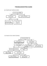
33. INFORMATION MENU ABOUT INTEGRIRATED CIRCUITS, CONNECTED TO I 2 C-<br />
BUS<br />
If you press i key (info) on remote control when the TV set is in service mode, you will get on the<br />
screen information about the version of current software (e.g.: VER:<strong>E9</strong>F1.6) and devices connected on I 2 C<br />
bus:<br />
SERVICE<br />
VER: <strong>E9</strong>F1.6<br />
VIDEO PR. OK TDA8843<br />
MSP 34XX OK WD:00<br />
SDA9288 XX SP:FF<br />
TUNER2 XX<br />
TDA 8540<br />
TDA8425<br />
Video processor: Bus controlled TV processor for video and audio signal<br />
MSP 34XX: Digital stereo sound processor<br />
SDA 9288: PIP processor<br />
TUNER2: Second tuner for PIP picture<br />
TDA 8540: SVHS video matrix switch<br />
TDA 8425: HI-FI Stereo audio processor for stereo through SCART connector<br />
If device is installed and properly connected on I 2 C bus it will respond with “OK” beside the name of<br />
device, otherwise there will be “XX” on this place.<br />
21
ELECTRICAL DIAGRAM OF MAIN CHASSIS <strong>E9</strong><br />
23
ELECTRICAL DIAGRAM OF MODULES FOR CHASSIS <strong>E9</strong><br />
24
Chassis <strong>E9</strong>-service manual<br />
OSCILLOGRAMS<br />
25
MAIN CHASSIS – COMPONENT SIDE<br />
26
Chassis <strong>E9</strong>-service manual<br />
ELECTRICAL DIAGRAMS OF SEPARATE MODULES OF CHASSIS <strong>E9</strong><br />
27
Chassis <strong>E9</strong>-service manual<br />
28
Chassis <strong>E9</strong>-service manual<br />
COMPONENT LOCATIONS ON SEPARATE MODULES OF CHASSIS <strong>E9</strong> –<br />
COMPONENT SIDE<br />
VK-<strong>E9</strong>T1 VK-<strong>E9</strong>T<br />
VK-<strong>E9</strong> VK-<strong>E9</strong>M<br />
29
Chassis <strong>E9</strong>-service manual<br />
PIP-<strong>E9</strong><br />
SOLDER SIDE<br />
COMPONENT SIDE<br />
30
Chassis <strong>E9</strong>-service manual<br />
ST-<strong>E9</strong><br />
S1-IN SVHS-<strong>E9</strong><br />
APD-<strong>E9</strong> AP-<strong>E9</strong><br />
31
Chassis <strong>E9</strong>-service manual<br />
SFTL-<strong>E9</strong> OC-<strong>E9</strong><br />
TP-CG<br />
TP-<strong>E9</strong> LZZ-<strong>E9</strong><br />
32
Chassis <strong>E9</strong>-service manual<br />
STD-E6 (module Dolby surround)<br />
ST-E6 (module stereo)<br />
33
Chassis <strong>E9</strong>-service manual<br />
LIST OF RECOMMENDED SPARE PARTS FOR CHASSIS AND MODULES<br />
INDEX CODE VALUE<br />
MAIN CHASSIS<br />
POSITION<br />
110 412499 C/EL 220U M400V C-9642<br />
90 414653 C/EL 100U M400V - // -<br />
415949 C/EL PR 5,0 2U2 M350V C-9709 5,0<br />
338557 C/EL PR 5,0 10U T250V C-9606 5,0<br />
414794 C/EL PR 5,0 47U M160V C-9605 5,0<br />
415947 C/EL TR 5,0 1U0 M250V C-9714 5,0<br />
415032 C/EL TR 5,0 2U2 M250V C-9202 5,0<br />
412517 C/K/KO/Z/2E4 * 2N2M250VAC C-9645<br />
W, 90 414655 C/MPP PR * U47 J 250V C-9707<br />
110, W28
Chassis <strong>E9</strong>-service manual<br />
INDEX CODE VALUE POSITION<br />
MAIN CHASSIS<br />
324669 D/SI/BY228 TA D-9706 20,0/H10<br />
410680 D/SI/BY399 TA D-9708 20,0/H10<br />
410680 D/SI/BY399 TA D-9605 15,0/H10<br />
410680 D/SI/BY399 TA D-9605 15,0/H10<br />
410680 D/SI/BY399 TA D-9607 15,0/H10<br />
410680 D/SI/BY399 TA D-9609 15,0/H10<br />
410680 D/SI/BY399 TA D-9614 15,0/H10<br />
424580 D/SI/BYT52G D-9302 12,5<br />
424580 D/SI/BYT52G D-9604 12,5<br />
424580 D/SI/BYT52G D-9703 12,5<br />
424580 D/SI/BYT52G D-9704 12,5<br />
424580 D/SI/BYT52G D-9709 12,5<br />
424279 D/SI/BYT52M TA D-9608 12,5<br />
415931 D/SI/BYW54 TA D-9610 12,5<br />
415931 D/SI/BYW54 TA D-9611 12,5<br />
415931 D/SI/BYW54 TA D-9612 12,5<br />
415931 D/SI/BYW54 TA D-9613 12,5<br />
417320 D/SI/BYW76 TA D-9602 15,0/H10<br />
417320 D/SI/BYW76 TA D-9707 15,0/H5<br />
68571 DIODE Z/ 2,7V/C/0,5W D-9711 10,0<br />
325626 DIODE Z/ 3,9V/C/0,5W TA D-9910 10,0<br />
304326 DIODE Z/33 V/C/0,5W TA D-9603 12,5<br />
110 416865 MAINS CHOKE 2X70 MH DU-9602<br />
90 416961 MAINS CHOKE 2X33 MH - // -<br />
429960 IC AT24C08-10 PC IC-9902<br />
415922 IC LM317T IC-9602<br />
415922 IC LM317T IC-9604<br />
322956 IC MC7805CT IC-9605<br />
415923 IC MC7808T IC-9603<br />
430695 IC SDA545XOTP-B 13 IC-9901<br />
415921 IC TDA4605-2 IC-9601<br />
419821 IC TDA7057AQ IC-9102<br />
110 425757 IC TDA8351 IC-9301<br />
90 425758 IC TDA8356/N5 - // -<br />
110-P 427444 IC TDA8843/N2C IC-9101<br />
90-P 427442 IC TDA8840/N2C - // -<br />
90-PS 427443 IC TDA8842/N2C - // -<br />
110-PS 427445 IC TDA8844/N2C - // -<br />
366430 IC VIDEO SWITCH IC-9104<br />
423189 TUNER FDL2473/84A TUN-9102<br />
EURO 431379 TUNER EL2787-84<br />
426141 CONNECTOR M / 7/2,5 90647-1007 K-9102A<br />
426141 CONNECTOR M / 7/2,5 90647-1007 K-9901A<br />
423429 CONNECTOR M/ / 2/2,5 MKS1951 K-9103A<br />
423427 CONNECTOR M/ / 4/2,5 MKS1954 K-9701<br />
424019 CONNECTOR M/ 3/2,5 90647-1003 K-9001A<br />
424019 CONNECTOR M/ 3/2,5 90647-1003 K-9301A<br />
423988 CONNECTOR M/4/2,5 90647-1004 K-9702A<br />
423989 CONNECTOR M/ 5/2,5 90647-1005 K-9104A<br />
35
Chassis <strong>E9</strong>-service manual<br />
INDEX CODE VALUE POSITION<br />
MAIN CHASSIS<br />
319045 CRYSTAL 4,4 MHz Q-9101<br />
431081 CRYSTAL 6 MHz Q-9901<br />
316831 FUSE HOLDER FOR VA-9601<br />
316831 FUSE HOLDER FOR VA-9602<br />
316831 FUSE HOLDER FOR VA-9603<br />
421055 METAL SHIELD E6/E7 MP-9101<br />
79039 PASTE SILICON P12 FOR HEATSINK 318695<br />
420919 WASHER CRT B10-301 ST 0330770023 PD-9201<br />
410208 MICA WASHER FOR IC-9602<br />
410208 MICA WASHER FOR IC-9604<br />
338708 MICA WASHER FOR T-9602<br />
410208 MICA WASHER FOR T-9705<br />
68503 IC SOCKET 8 FOR IC-9902<br />
68503 IC SOCKET 8 FOR IC-9903<br />
419741 R/NTC B57234-S709-M R-9629<br />
338569 R/PL TA R47 J 0,5 W R-9703 15,0<br />
415965 R/PL TA 5K1 J 0,33 W R-9610 10,0<br />
68152 R/PL TA 100K J 0,25 W R-9615 IN SER. W. R120K<br />
52777 R/PL TA 120K J 0,25 W R-9615 IN SER. W. R100K<br />
372123 R/PL/VR TA 2R2 J 0,33W R-9121 15,0/H10<br />
372123 R/PL/VR TA 2R2 J 0,33W R-9156 15,0/H10<br />
372123 R/PL/VR TA 2R2 J 0,33W R-9715 15,0/H10<br />
372123 R/PL/VR TA 2R2 J 0,33W R-9953 12,5<br />
372123 R/PL/VR TA 2R2 J 0,33W R-9977 12,5<br />
421131 R/PL/VR TA 47R J 0,33W R-9304 15,0/H10<br />
421131 R/PL/VR TA 47R J 0,33W R-9609 15,0/H10<br />
411567 R/PL/VR TA 120R J 0,75W R-9210 20,0/H10<br />
415009 R/PL/VR/NG TA 1K0 J 0,5 W R-9707 15,0/H10<br />
411572 R/PL/VR/VT TA R15 K 0,75W R-9622 15,0/H10<br />
411574 R/PL/VR/VT TA R22 K 0,4 W R-9710 15,0/H15<br />
411574 R/PL/VR/VT TA R22 K 0,4 W R-9713 15,0/H15<br />
419823 R/PLK 0204 TA 2K05 F 0,25 W R-9618 12,5<br />
330380 R/PLK 0204 TA 3K F 0,25 W R-9118 10,0<br />
330380 R/PLK 0204 TA 3K F 0,25 W R-9308 12,5<br />
313601 R/PLK 0204 TA 10K F 0,25 W R-9909 10,0<br />
429553 R/PLK 0204 TA 39K F 0,25 W R-9122 12,5<br />
419824 R/PLK 0204 TA 243R F 0,25 W R-9616 12,5<br />
419824 R/PLK 0204 TA 243R F 0,25 W R-9623 12,5<br />
419825 R/PLK 0204 TA 715R F 0,25 W R-9625 12,5<br />
416940 R/PLK/VN TA 220K J 1 kV R-9701 12,5<br />
433776 R/PLK/VN TA 820K J 1,6KV R-9613 12,5<br />
316701 R/PLKO TA R82 J 1W R-9702 15,0<br />
420920 R/PLKO TA 1R0 J 1W R-9207 15,0/H10<br />
420920 R/PLKO TA 1R0 J 1W R-9306 20,0/H10<br />
429521 R/PLKO TA 2R7 J 4W R-9714 20,0/H15<br />
419822 R/PLKO TA 10R J 2W R-9725 20,0/H20<br />
416508 R/PLKO TA 22K J 2W R-9603 20,0/H15<br />
415953 R/PLKO TA 27K K 6W R-9624 35,0/H20<br />
415952 R/PLKO TA 47K J 1,5W R-9606 20,0/H10<br />
36
Chassis <strong>E9</strong>-service manual<br />
INDEX CODE VALUE POSITION<br />
MAIN CHASSIS<br />
429522 R/PLKO TA 75K J 4 W R-9604 20,0/H15<br />
417319 R/PLKO TA 120R K4 W R-9305 20,0/1-110<br />
430531 R/PTC 16:9 T209 R-9628<br />
338709 CLIP IC FOR IC-9102<br />
338709 CLIP IC FOR IC-9301<br />
338709 CLIP IC FOR IC-9602<br />
338709 CLIP IC FOR IC-9604<br />
338709 CLIP IC FOR T-9602<br />
338709 CLIP IC FOR T-9701<br />
422699 CLIP IC FOR T-9705<br />
423137 T/FET/BUZ90A T-9602<br />
338580 T/NPN/AF/BC639 TR T-9703<br />
411262 T/NPN/BC547B TR T-9104<br />
411262 T/NPN/BC547B TR T-9105<br />
411262 T/NPN/BC547B TR T-9106<br />
411262 T/NPN/BC547B TR T-9108<br />
411262 T/NPN/BC547B TR T-9601<br />
411262 T/NPN/BC547B TR T-9603<br />
411262 T/NPN/BC547B TR T-9702<br />
411262 T/NPN/BC547B TR T-9706<br />
411262 T/NPN/BC547B TR T-9902<br />
411262 T/NPN/BC547B TR T-9904<br />
411262 T/NPN/BC547B TR T-9905<br />
411262 T/NPN/BC547B TR T-9906<br />
411262 T/NPN/BC547B TR T-9908<br />
110, W 415900 T/NPN/BU508AF T-9701<br />
90 413787 T/NPN/BU508D/BU508DF/BU508DR - // -<br />
415928 T/NPN/PH2369 TR T-9109<br />
415928 T/NPN/PH2369 TR T-9903<br />
411261 T/PNP/BC212B/BC557B TR T-9107<br />
411261 T/PNP/BC212B/BC557B TR T-9110<br />
411261 T/PNP/BC212B/BC557B TR T-9704<br />
411261 T/PNP/BC212B/BC557B TR T-9911<br />
414036 T/PNP/BD242 T-9705<br />
D, SW 420389 TRANSFORM. SMPS E6 TR-9601<br />
ST 425763 TRANSFORM. SMPS <strong>E9</strong> 110 - // -<br />
90 425764 TRANSFORM. SMPS <strong>E9</strong> 90 - // -<br />
W 427975 TRANSFORM.HV <strong>E9</strong> 16:9 TR-9701<br />
110 425765 TRANSFORM.HV <strong>E9</strong> - // -<br />
90 425766 TRANSFORM.HV <strong>E9</strong> 90 - // -<br />
378773 TRANSFORM. DRIVER G2/E5 TR-9702<br />
110 339150 LINEARITY COIL 12-25 L-9701<br />
90 413801 LINEARITY COIL G4/E5 - // -<br />
W-32« 429470 LINEARITY COIL EKM 12-126 - // -<br />
W-28« 429703 LINEARITY COIL EKM 12-127 - // -<br />
110-34« 433863 LINEARITY COIL EKM 12-134 - // -<br />
427974 COIL EW <strong>E9</strong> L-9703<br />
21108 FUSE T 1,25 A L 250V VA-9601<br />
21108 FUSE T 1,25 A L 250V VA-9602<br />
37
Chassis <strong>E9</strong>-service manual<br />
INDEX CODE VALUE POSITION<br />
MAIN CHASSIS<br />
431998 FUSE T2A E 250V VA-9603<br />
MODULES<br />
427639 MODULE KD-E6/9 K-1201 - K-1203<br />
428383 MODULE SVHS-<strong>E9</strong> K-401 - K402<br />
D 429975 MODULE APD-<strong>E9</strong> K-001<br />
D 430836 MODULE STD-E6/9 II K-500 - K-504<br />
ST MODULE ST E-6/9 - // -<br />
MODULE ST E-9 - // -<br />
433983 MODULE PIP2 <strong>E9</strong>/1 S2 K-800 - K-805<br />
431365 MODULE LZZ-<strong>E9</strong>/1 K-703, K-704<br />
MODULE KD<br />
52819 FILTER CER.SFE 5,5 MHz 5,5MC Q-1204<br />
413802 FILTER CER.TRAP TPS 5,5 MB Q-1202<br />
419135 FILTER OFW G 1968 F-1201<br />
423180 IC TDA9800 IC-1201<br />
416507 TUNER FL 2477/84 TUN-1201<br />
420732 CONNECTOR Z/32/ 3/2,54 K-1202B<br />
420735 CONNECTOR Z/32/ 4/2,54 K-1201 B<br />
423179 REFEREN. COIL 77,8MHZ L-1201<br />
413792 CONTACT HEADER / 2/2,5 K-1203B<br />
51900 P/PL/NA/LIN/V 25K 0,05W P-1201<br />
411262 T/NPN/BC547B TR T-1201<br />
411262 T/NPN/BC547B TR T-1203<br />
411261 T/PNP/BC212B/BC557B TR T-1202<br />
MODULE SVHS<br />
419731 IC TDA8540 IC-401<br />
427631 CONNECTOR Z/32/13/2,54 K-401 B<br />
420734 CONNECTOR Z/32/ 5/2,54 K-402B<br />
423419 CONNECTOR M/ / 3/2,5 MKS2953 K-404B<br />
STERO MODULE<br />
419734 DIODE Z/ 8,2V/C/0,5W TA D-521 12,5<br />
D 425590 IC DPL3519A IC-523<br />
D 420187 IC MSP3400 IC-521<br />
N 425622 IC MSP3410D - // -<br />
433927 IC MSP3401G - // -<br />
378782 IC TDA2545A IC-523<br />
422733 IC TDA4445B IC-524<br />
419728 IC TDA7050 IC-522<br />
338638 CONNECTOR Z/ /3/2,5 K-506B<br />
420735 CONNECTOR Z/32/ 4/2,54 K-501 B<br />
420734 CONNECTOR Z/32/ 5/2,54 K-504B<br />
420736 CONNECTOR Z/32/11/2,54 K-502B<br />
423419 CONNECTOR M/ / 3/2,5 MKS2953 K-506A<br />
423419 CONNECTOR M/ / 3/2,5 MKS2953 K-508A<br />
423417 CONNECTOR M/ / 7/2,5 MKS2957 K-507A<br />
423991 CONNECTOR M/ 3/2,5 90649-1003 K-51 OA<br />
420188 CRYSTAL 18,432MHZ 4730006848 Q-521<br />
424135 REFEREN. COIL 38,9MHZ KZS-73 L-521<br />
38
Chassis <strong>E9</strong>-service manual<br />
INDEX CODE VALUE POSITION<br />
413792 CONTACT HEADER 2/2,5 K-503B<br />
414955 R/PL/VR/VT TA 10R K 0,4 W R-555 12,5<br />
411262 T/NPN/BC547B TR T-523<br />
411262 T/NPN/BC547B TR T-524<br />
411262 T/NPN/BC547B TR T-525<br />
MODULE OC<br />
419754 DIODE Z/130 V/C/2W TA D-661 12,5<br />
419736 IC SFH617 IC-661<br />
330418 P/PL/NA/LIN/H 1K 0,05W P-661<br />
338577 R/PLK/VN TA 10M K 10 kV R-665 22,5<br />
411262 T/NPN/BC547B TR T-661<br />
MODULE AP<br />
424406 IC TDA2616Q IC-91302<br />
423425 CONNECTOR M/ / 7/2,5 MKS1957 K-91301<br />
424019 CONNECTOR M/ 3/2,5 90647-1003 K-91303<br />
338709 CLIP IC FOR IC-91302<br />
411262 T/NPN/BC547B TR T-91301<br />
MODULE LZZ<br />
415949 C/EL PR 5,0 2U2 M350V C-9752 5,0<br />
427971 C/MPP PR22,5 1U0 J 400V C-9751 22,5<br />
414037 C/PP PR * 2200P J 1,6KV C-9753<br />
51666 D/SI/1N4148 TA D-9752 12,5<br />
51666 D/SI/1N4148 TA D-9753 12,5<br />
51666 D/SI/1N4148 TA D-9754 12,5<br />
424580 D/SI/BYT52G D-9751 15,0/H10<br />
415923 IC MC7808T IC-9751<br />
423987 CONNECTOR M/ 2/2,5 90647-1002 K-9751<br />
415009 R/PL/VR/NG TA 1 KO J 0,5 W R-9751 15,0/H10<br />
419485 T/NPN/337 T-9751<br />
419485 T/NPN/337 T-9753<br />
314862 T/PNP/BC327 T-9752<br />
431359 BRIDGE COIL <strong>E9</strong>/2 L-9751<br />
MODULE PIP<br />
412710 C/ELB TR 5,0 10U M 40V C-9834 5,0<br />
412710 C/ELB TR 5,0 10U M 40V C-9845 5,0<br />
412710 C/ELB TR 5,0 10U M 40V C-9846 5,0<br />
51666 D/SI/1N4148 TA D-9800 12,5<br />
51666 D/SI/1N4148 TA D-9802 12,5<br />
412464 D/SI/BAT85 TA D-9801 12,5<br />
420773 IC SDA9288 IC-9802<br />
425756 IC TDA8310A IC-9801<br />
366430 IC VIDEO SWITCH IC-9803<br />
427630 CONNECTOR Z/32/ 2/2,54 K-9803A<br />
420732 CONNECTOR Z/32/ 3/2,54 K-9801 B<br />
420734 CONNECTOR Z/32/ 5/2,54 K-9802B<br />
420734 CONNECTOR Z/32/ 5/2,54 K-9805B<br />
427631 CONNECTOR Z/32/13/2,54 K-9804B<br />
423418 CONNECTOR M/ / 4/2,5 MKS2954 K-9806B<br />
319045 CRYSTAL 4,4 MHz Q-9801<br />
420070 CRYSTAL 20,48MHZ Q-9802<br />
39
Chassis <strong>E9</strong>-service manual<br />
INDEX CODE VALUE POSITION<br />
413792 CONTACT HEADER / 2/2,5 K-9800B<br />
426647 CONTACT HEADER 36/ 2/2,54 K-9803A<br />
420581 CONTACT HEADER 36/ 3/2,54 K-9801A<br />
420580 CONTACT HEADER 36/ 5/2,54 K-9802A<br />
420580 CONTACT HEADER 36/ 5/2,54 K-9805A<br />
426571 CONTACT HEADER 36/13/2,54 K-9804A<br />
372123 R/PL/VR TA 2R2 J 0,33W R-9817 10,0/H10<br />
372123 R/PL/VR TA 2R2 J 0,33W R-9826 12,5<br />
415206 T/NPN/SMD BC847B T T-9801<br />
415206 T/NPN/SMD BC847B T T-9807<br />
415206 T/NPN/SMD BC847B T T-9808<br />
415206 T/NPN/SMD BC847B T T-9810<br />
415206 T/NPN/SMD BC847B T T-9811<br />
415206 T/NPN/SMD BC847B T T-9812<br />
427809 T/NPN/SMD PMBT2369 T-9804<br />
411261 T/PNP/BC212B/BC557B TR T-9809<br />
414025 T/PNP/SMD BC857 T T-9806<br />
LEGEND: 110............110 picture tube 90..............90 picture tube<br />
W..............16:9 picture tube W-28«.........28
Chassis <strong>E9</strong>-service manual<br />
NOTES:<br />
41