
Create successful ePaper yourself
Turn your PDF publications into a flip-book with our unique Google optimized e-Paper software.
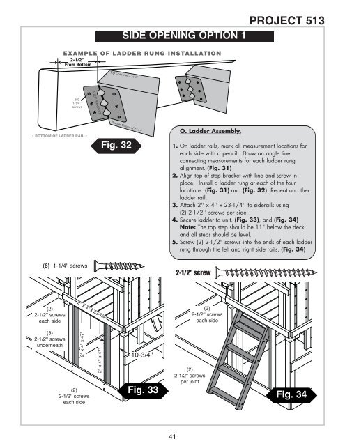
Top Corner of 2'' x 4''SIDE OPENING OPTION 1<strong>PROJECT</strong> <strong>513</strong>EXAMPLE OF LADDER RUNG INSTALLATION2-1/2''2- 3/4''From BottomSTEP BRACKET(6)1-1/4''screws• BOTTOM OF LADDER RAIL •Bottom Corner of 2'' x 4''Fig. 32O. Ladder Assembly.1. On ladder rails, mark all measurement locations foreach side with a pencil. Draw an angle lineconnecting measurements for each ladder rungalignment. (Fig. 31)2. Align top of step bracket with line and screw inplace. Install a ladder rung at each of the fourlocations. (Fig. 31) and (Fig. 32). Repeat on otherladder rail.3. Attach 2'' x 4'' x 23-1/4'' to siderails using(2) 2-1/2'' screws per side.4. Secure ladder to unit. (Fig. 33), and (Fig. 34)Note: The top step should be 11" below the deckand all steps should be level.5. Screw (2) 2-1/2" screws into the ends of each ladderrung through the left and right side rails. (Fig. 34)(6) 1-1/4'' screws2-1/2'' screw(2)2-1/2'' screwseach side2'' x 4'' x 23-1/4''(3)2-1/2'' screwseach side(3)2-1/2'' screwsunderneath2'' x 4'' x 47''(2)2-1/2'' screwseach side2'' x 4'' x 47''10-3/4''Fig. 33(2)2-1/2'' screwsper jointFig. 3441