EZiSYSTEM User Manual - Cable Detection
EZiSYSTEM User Manual - Cable Detection
EZiSYSTEM User Manual - Cable Detection

Create successful ePaper yourself
Turn your PDF publications into a flip-book with our unique Google optimized e-Paper software.
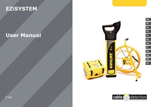
<strong>EZiSYSTEM</strong>ENDEES<strong>User</strong> <strong>Manual</strong>FRPLRUHUITNLDANOSVV 1.0
<strong>EZiSYSTEM</strong><strong>User</strong> <strong>Manual</strong>Version 1.0English
<strong>EZiSYSTEM</strong>, IntroductionIntroduction2PurchaseCongratulations on your purchase of a <strong>EZiSYSTEM</strong> instrument.This manual contains important safety directions as well as instructions for setting up theproduct and operating it. Refer to "9 Safety Directions" for further information.Read carefully through the <strong>User</strong> <strong>Manual</strong> before you switch on the product.Product identificationThe model and the serial number of your product are indicated on the type plate.Enter the model and serial number in your manual and always refer to this informationwhen you need to contact your agency or <strong>Cable</strong> <strong>Detection</strong> authorised service workshop.Type:Serial No.:__________________________________________________
SymbolsValidity of this manualThe symbols used in this manual have the following meanings:Type Danger Warning CautionDescriptionIndicates an imminently hazardous situation which, if not avoided, willresult in death or serious injury.Indicates a potentially hazardous situation or an unintended use which, ifnot avoided, could result in death or serious injury.Indicates a potentially hazardous situation or an unintended use which, ifnot avoided, may result in minor or moderate injury and/or appreciablematerial, financial and environmental damage.Important paragraphs which must be adhered to in practice as they enablethe product to be used in a technically correct and efficient manner.This manual applies to all <strong>EZiSYSTEM</strong> instruments, which are the i-Series. Differencesbetween the various instruments and models are marked and described.<strong>EZiSYSTEM</strong>, Introduction 3
<strong>EZiSYSTEM</strong>, Table of ContentsTable of Contents4In this manual Chapter Page1 General Information 71.1 How to Use this <strong>Manual</strong> 71.2 i-Series General Information 81.3 i-Series Instruments and Accessories 102 How to Use the Locator 112.1 General Information 112.2 Locator Overview 122.3 Locator Setup and Information 142.4 Hazard Zone 162.5 How to Locate a Service 182.6 Wireless Data Communication, where applicable 273 How to Use the Transmitter 293.1 General information 293.2 Transmitter Overview 313.3 How to Locate a Service Using the Transmitter 334 How to Use the Conductive Rod 374.1 General Information 374.2 Conductive Rod Overview 374.3 How to Locate a Service Using the Conductive Rod 38
5 How to Use the Signal Clamp 405.1 General Information 405.2 Signal Clamp Overview 405.3 How to Locate a Service Using the Signal Clamp 416 How to Use the Property Connection Set 436.1 General Information 436.2 Property Connection Set Overview 436.3 How to Locate a Service Using the Property Connection Set 447 How to Use the Sonde 467.1 General Information 467.2 Sonde Overview 467.3 How to Locate a Service Using the Sonde 498 Care and Transport 518.1 Transport 518.2 Storage 518.3 Cleaning and Drying 529 Safety Directions 539.1 General Introduction 539.2 Intended Use 539.3 Limits of Use 549.4 Responsibilities 549.5 Hazards of Use 559.6 Electromagnetic Compatibility EMC 599.7 FCC Statement, Applicable in U.S. 62<strong>EZiSYSTEM</strong>, Table of Contents 5
<strong>EZiSYSTEM</strong>, Table of Contents10 Technical Data 6510.1 Locator i-Series Technical Data 6510.2 Transmitter Technical Data 6910.3 Conductive Rod Technical Data 7210.4 Sonde Technical Data 7410.5 Property Connection Set Technical Data 7610.6 Signal Clamp Technical Data 7811 International Limited Warranty 80Appendix A Functional Checks 81A.1 Locator Functional Check 81A.2 Transmitter Functional Check 85A.3 Conductive Rod Functional Check 90A.4 Sonde Functional Check 92Appendix B World Frequency Zones 95Index 996
1 General Information1.1 How to Use this <strong>Manual</strong>Naming conventionIt is recommended to set up the product while reading through this manual.EZiCAT i500, EZiCAT i550 are hereinafter referred to as Locator.Differences between the models are marked and described.EZiTRACE is hereinafter referred to as Transmitter.EZiROD is hereinafter referred to as Conductive Rod.IndexInstrument labelThe index is at the back of the manual.On the Locator and Transmitter you will find a label that shows some important informationby means of illustrations. You will find some of these illustrations in this manual too.This should help to get a clear connection between the instrument label and the informationin this manual.<strong>EZiSYSTEM</strong>, General Information 7
<strong>EZiSYSTEM</strong>, General Information1.2 i-Series General Information8DescriptionLocators are used to detect buried conductive services emitting an electromagnetic signalwhich is generated by a current passing through the service.Transmitters are used to apply a distinct signal to conductive services, which may notradiate electromagnetic signals or may need to be traced for a specific purpose.The Transmitter is required to make a depth measurement.The Locators and Transmitters described within this manual will greatly increase the detectionprocess and help to reduce the dangers and costs associated with service strikes. Butthe very nature of electromagnetic location is dependent on the services being conductive(metallic) and radiating a signal as current flows through them.It is important to remember that a Locator on its own will not detect all services and careshould be taken when excavating. It is generally accepted that a safe system of work shouldbe adopted which would include planning the work in advance, the use of utility maps, theuse of Locators and Transmitters, and the use of safe digging practices. CautionThe absence of a positive indication does not guarantee the non-existence of a service.Services without a detectable signal may be present.The Locators can only locate non-metallic services such as plastic pipes, typically used bythe water and gas utilities, with the use of appropriate accessories.Precautions:Always excavate with care.
AccessoriesFunctional CheckDesigned to increase the detection of services with no (or little) signals on them. Generallywork in conjunction with the Locator and Transmitter.Designed to demonstrate the equipment is working satisfactorily in between service intervals.Refer to "Appendix A Functional Checks" for more information.<strong>EZiSYSTEM</strong>, General Information 9
F<strong>EZiSYSTEM</strong>, General Information1.3 i-Series Instruments and Accessories10General informationi-Series instrumentsoverviewThe i-Series is a collection of products used to locate buried metallic and nonmetallic services.iaba) Locatorb) Transmitteri-Series accessories overviewab c d ea) Conductive Rod (nonmetallic service tracer)b) Extension <strong>Cable</strong>c) Property ConnectionSetd) Signal Clampe) Sonde
2 How to Use the Locator2.1 General InformationOperating modes • Passive modes (Power and Radio)• Active modes (8 kHz and 33 kHz)• Auto mode (Combined Power and Radio modes)Electromagnetic signalsPassive signalsActive tracingDepth indication(i550 only)Wireless communication(Bluetooth)Hazard zonePeak holdAn electromagnetic signal radiates from buried conductive services as an electrical currentflows through them. The Locator processes these signals and displays their presence.Some signals are already present on buried services and can be readily detected by theLocator. We call these passive signals. These signals are generated by power distributionsystems and radio transmitters.Some conductive services do not emit passive signals. These services may be traced byapplying a signal to the service by using a transmitter.Depth indication is only available with the i550 Locator used in conjunction with the Transmitteror Sonde. The displayed depth is to the centre of the service or to the Sonde.Data can be wirelessly transferred from the Bluetooth enabled Locator to devices which aredesigned to accept the information.Provides an additional alarm, indicating the close proximity of a service emitting a Power,8 kHz or 33 kHz signal.Assists in pinpointing a service by displaying the peak reading for a short period of time.<strong>EZiSYSTEM</strong>, How to Use the Locator 11
<strong>EZiSYSTEM</strong>, How to Use the Locator2.2 Locator Overview12Locator main partsFaibcdefa) Display PanelContains the operational controls.b) Speakers (mounted internally left and right)Active at power on and when a signal is detected.c) On/Off TriggerPress and hold the trigger to activate the Locator.Release the trigger to deactivate.d) Battery Hatch ReleasePressing the yellow release button unlocks thebattery hatch allowing access to the batterycompartment.e) Battery Compartment6 x LR6 (AA) alkaline batteries are used. Replace allbatteries when indicated.f) Case FootThe case foot can be replaced if it is worn. Contact your agency or <strong>Cable</strong> <strong>Detection</strong> authorisedservice workshop.
Display panel overviewabcdefghijka) Signal Strength IndicatorIndicates the response of the Locator to a signal(service).b) Mode IndicatorsDisplays the selected mode: Power, Radio, 8 kHz,33 kHz, Auto (as shown, from bottom to top).c) Function ButtonSelects operating mode.d) Light SensorAutomatically switches the displays backlight onor off to suit light conditions.e) Battery IndicatorIndicates the battery condition. Segment illuminationdecreases as battery condition declines.Replace the batteries when the battery indicator isempty.f) Bluetooth (optional extra)Indicates the Locator is paired to another device.g) WrenchIndicates the Locator requires periodic service orunit is faulty.h) Measurement Unit (Depth indication with i550)Indicates depth indication is in metric or feet and inches.i) Display ReadoutAlpha numeric matrix indicates system set up and depth indication.j) Depth Mode IndicatorsIndicates a depth reading to a service or a Sonde (i550 only). Service icon used to indicateHazard zone on i500 and i550.k) i ButtonUsed to access the user settings and to provide a depth readout for the i550.<strong>EZiSYSTEM</strong>, How to Use the Locator 13
<strong>EZiSYSTEM</strong>, How to Use the Locator2.3 Locator Setup and Information14Locator settingsThe i-Series Locators offer a range of settings which the operator can adjust to their ownpreference. It also displays additional service and contact information as detailed.SettingDescriptionESTPerforms a function check on the locators hardware and software,displaying PAS if the Locator is within predefined tolerance or ERR if thelocator it is not.H.ZSwitches hazard zone on or off.VOL Adjust volume level (0 - 10).HLDAdjust peak hold duration (0 - 5 seconds).SSIDisplays a numeric signal strength indicator.CST Adjusts display’s contrast (0 - 15).M/IDisplays unit of measurement.CALDisplays the next service date DD/MM/YY.CONDisplays supplier/company name.TELDisplays supplier/company telephone number.I.DDisplays the operator’s name.PWRDisplays the power mode regional setting. Refer to "Appendix B WorldFrequency Zones" for more information.SR#Displays unit serial number.VERDisplays software version
Accessing and adjustingthe settings Danger1. Switch the Locator on.2. Ensure the Locator is in Power mode.If required, press Function Button to select mode.3. Depress i Button for 2 seconds. The user settings will be displayed in the display readout.4. Press Function Button to toggle through to desired setting.5. Press i Button to select the setting.6. Press Function Button to activate/adjust.7. Press i Button to store and exit.The Locator may fail to detect electrical services in Power mode if an incorrect powersetting is used.Precautions:Before use, verify the Locator is setup to be compatible with mains frequency supply inyour country. Options are 50 or 60 Hz. Refer to "Appendix B World Frequency Zones" formore information.Contact your agency or <strong>Cable</strong> <strong>Detection</strong> authorised service workshop if your unit is incorrectlyconfigured for your region.Changing the batteryFi1. Replace the batteries when the batterystatus indicator is empty.2. Press the yellow release button to unlockthe Battery Hatch. Remove the batteryholder from the Locator.3. Replace all batteries with six new,LR6 (AA) batteries.Alkaline batteries should be used.<strong>EZiSYSTEM</strong>, How to Use the Locator 15
<strong>EZiSYSTEM</strong>, How to Use the Locator2.4 Hazard Zone16DescriptionProvides an additional warning to the close proximity of buried services and functions inthe following modes:• Power• 8 kHz• 33 kHz• Auto mode (Power mode only)Hazard zone status indicatorsStatus indicatorDescriptionHazard zone is switched on.Hazard zone on and is alarming.Hazard zone is switched off.
CautionThe absence of a positive indication does not guarantee the non-existence of a service.Services without a detectable signal may be present.The Locators can only locate non-metallic services such as plastic pipes, typically used bythe water and gas utilities, with the use of appropriate accessories.Precautions:Always excavate with care.<strong>EZiSYSTEM</strong>, How to Use the Locator 17
<strong>EZiSYSTEM</strong>, How to Use the Locator2.5 How to Locate a Service18Start up testThe following test sequence will take place every time the Locator is activated.On test Test pattern Info on labelAudio OutputOn throughout testsequenceSignal Strength indicatorMode indicatorsBattery indicatorBluetooth and wrenchMeasurement unit,display readout, depthmode indicatorScrolls through insequence onceBriefly illuminatedOn throughoutBriefly illuminatedBriefly illuminated500&550FiLocating processThe unit will then go into Power mode maximum sensitivity.The locating process is split into three steps:• Sweep Search• Pinpointing the service• Direction of the service
Sweep SearchFiThe unit will automatically select Power mode andmaximum sensitivity.Auto mode combines thebenefit of simultaneousdetection in Power andRadio modes and helps toconfirm the presence ofservices upon initial siteoccupation. Improved definitionof the service will beprovided by single modeoperation.1. Define the area to be excavated.2. In Power mode cross the site from left to right keeping the Locator upright, takingcare not to swing the unit. Turn through 90 degrees and repeat.Ensure that the Locator is held in an upright position and close to the ground.3. Continue the sweep until either a signal is located or you are satisfied that the areahas been adequately tested.In the presence of a service emitting a traceable signal a tone will be emittedand the signal strength indicator will rise and fall as you pass over it.4. Repeat the Sweep Search process in Radio mode.The Sweep Search must be conducted in Power and Radio modes as aminimum, as not all services (including some electrical ones) emit a powersignal. These services may be found using Radio mode or active modes.<strong>EZiSYSTEM</strong>, How to Use the Locator 19
<strong>EZiSYSTEM</strong>, How to Use the Locator20Hazard zone can be operated in Power, 8 kHz, 33 kHz and Auto modes andprovides an additional alarm to the presence of buried services which may bewithin close proximity.Pinpointing the serviceRetrace your steps to the areawhere the highest signal reading(peak response) was obtained.The service is directly below theLocator when the signal strengthindicator is at its maximum. Theaudio output will automaticallyadjust to facilitate pinpointingover the service, and automaticallyreset when the signalstrength indicator drops to itsminimum position.• Always use chalk or paint to mark services, never pegs.• The signal strength indicator does not indicate the size, depth or type of a service.Peak holdWhen activated peak hold will show the highest peak reading obtained during the pinpointprocess. The displayed reading can be adjusted between 0 to 5 seconds.
550Detecting direction of theservice1. Position the Locator directlyover the service.2. Rotate the Locator on its axis.3. The blade of the Locator will bein line with the service whenthe signal strength indicator isat its minimum.Depth Indication(i550 only)+Fii1. Apply a signal to the service.Refer to "3 How to Use theTransmitter" for more information.2. Select either 33 kHz or 8 kHzmodes to suit the the Transmitter’soutput. Position theLocator directly over, and at90 degrees to the direction ofthe service.3. Press and release the i Button.4. The display readout will indicatethe depth of the serviceand the Line mode icon will bedisplayed.<strong>EZiSYSTEM</strong>, How to Use the Locator 21
<strong>EZiSYSTEM</strong>, How to Use the Locator22• Activating Sonde depth will provide an inaccurate readout. • Always use chalk or paint to mark services, never pegs or other material which aredriven into the ground.• Additional services may be within the excavation zone, as well as the service you aretaking a depth reading from.• The reading will be more accurate when taken over a straight run, where the servicedoes not bend, or have a service crossing it or coming off it.Depth shown and actual depth:d1 Depth shown on the EZiCAT = depth to thecentre of the line.d2 Actual depth of the service.Note the difference between d1 and d2 ! WarningThe depth reading might not reflect the real depth if your Locator picks up the signalinduced into the service by the Transmitter. This signal is radiated from the centre of theservice.This is even more important when the signal is produced by a Sonde, lying in a large diameterconduit!Precautions:Always compensate depth reading for service size.
550Measuring Sonde depth(i550 only)+Fii1. Switch on the sonde and set tothe required frequency. Referto "7 How to Use the Sonde" formore information.2. Select either 33 kHz or 8 kHzmode to suit the Sonde’soutput.Position the Locator directlyover, and in line with theSonde. Refer to "7 How to Usethe Sonde" for more information.3. Press and hold down thei Button for 2 seconds until thedashed lines have scrolledthrough once.4. The display readout will indicatethe depth of the Sondeand the Sonde mode icon willbe displayed.• Activating line depth will provide an inaccurate readout.• Always use chalk or paint to mark services, never pegs or other material which aredriven into the ground.• Additional services may be within the excavation zone, as well as the service you aretaking a depth reading from.<strong>EZiSYSTEM</strong>, How to Use the Locator 23
<strong>EZiSYSTEM</strong>, How to Use the LocatorDepth shown and diameter:24Take special care when the signal is producedby a sonde, lying in a large diameter conduit! WarningDepth code informationThe depth reading may not indicate the real depth of the service, especially if the sonde islying at the base of a large diameter duct.Precautions:Always compensate depth reading for service size.Information code Description Information on instrumentlabelThe service is too shallow to register properly.metresft-inchmetresft-inch0.3 m1ft
Information code Description Information on instrumentlabelmetresThe service is too deep.metresft-inchft-inchThe signal received by the Locator is toosmall to register properly.3.0 m10ftThe signal received by the Locator is toolarge to register properly.<strong>EZiSYSTEM</strong>, How to Use the Locator 25
<strong>EZiSYSTEM</strong>, How to Use the Locator26Information code Description Information on instrumentlabelDepth function not available. The Locator isset to the wrong mode for a depth readingto be taken.
2.6 Wireless Data Communication, where applicableBluetoothBluetooth connectivity is an optional extra available on the i500 and i550 Locators. Data canbe wirelessly transferred from the Locator to a suitable data logging device, enabling theoperator to capture information about the Locator’s status and the service depth. When theLocator is paired to a suitable logger, the Bluetooth symbol will flash, and the unit willtransmit data periodically.Important information for pairing:• The Locator must be switched on throughout the process• Follow the instructions on the logger for pairing. Refer to the manufacturer’s instructions.Pairing informationDevice Name:‘Model Number’ - ‘Serial Number’for example: 550-000001Pass key: 12345• The Bluetooth symbol will flash continually when the devices have successfully paired. • When a depth reading has been taken, the Locator will display LOG. To transfer theinformation to the data logger press the i Button whilst LOG is displayed.• Whilst the Locator is calculating depth the data output stops.• If there is no wireless communication then the LOG function will not be displayed andthe unit will function as a Locator.• The Locator will output ASCII text.Refer to "ASCII text description" for more information.<strong>EZiSYSTEM</strong>, How to Use the Locator 27
<strong>EZiSYSTEM</strong>, How to Use the LocatorASCII text descriptionASCII output pattern:DVxxxSNxxxxSVxxTMxxxxDTdd/mm/yyCMxxCMxSTxxBTxxMDxxSSxxUMxxDPXX28Data output Range Example value DescriptionDV 000 to 999 550 Model identifierSN 000000 to 999999 123456 Serial numberSV 0.00 to 9.99 3.01 Software versionTM 00:00 to 23:59 08:30 Time: hh:mm(default = 00:00; no RTC fitted)DT 00/00/00 to 31/12/99 01/12/10 Date: dd/mm/yy(default = 00/00/00; no RTC fitted)CM 00 to 15 12 Number of months until next calibration(00 to 15)ST 0 or 1 0 Self test: 0 = Pass, 1 = FailBT 0 to 9 7 Battery level: 0 = Empty,9=GoodMD 0 to 4 3 Mode: 0 = Power, 1 = Radio,2=8kHz, 3=33kHz, 4=AutoSS 01 to 48 16 Signal strength: 01 to 48UM M or I M Units of measurements:M or I (Metres or Imperial)DP 0.30 to 3.00 or --- 125 Depth value displayed dependson value for UM.
3 How to Use the Transmitter3.1 General informationTracing signalOperating modeDescriptionThe Transmitter applies an electrical current signal onto a buried metallic service, whichenables the service to be traced and identified by the Locator operating in the same mode.There are three operating modes for onsite flexibility:• 8 kHz for congested site operation• 33 kHz for general usage• Combined 8 kHz and 33 kHz available in Connection mode, enabling rapid selection andconvenience on congested sites. The Locator can be used in either mode.Active tracing is a term frequently used when a Transmitter is used to apply a signal to aservice enabling it to be traced. The use of a Transmitter will greatly improve the detectionof services especially ones which may not have a signal on them.The signal from the Transmitter can be applied to services in two ways:• Induction mode (8 kHz or 33 kHz):Induction is a quick and simple way to apply a signal to a service without the need tomake any physical connection to it. The Transmitter uses an internal aerial to transmitthe signal, therefore it should be noted that the signal will apply itself to additional serviceswithin close proximity to the Transmitter.• Connection mode (8 kHz or 33 kHz or combinded 8 kHz and 33 kHz):This is the most efficient way of applying a signal to a service, and should be used wheneverpossible. The Transmitter’s cable set or any of the available accessories areconnected to the service which is to be traced or identified.<strong>EZiSYSTEM</strong>, How to Use the Transmitter 29
<strong>EZiSYSTEM</strong>, How to Use the Transmitter30• 8 kHz is less likely to apply itself to additional services making tracing in areas of multiple services easier.• 33 kHz is suitable for general site use.• Combined 8 and 33 kHz (Connection mode only) is useful in congested areas wheneither 8 or 33 kHz may provide a better result. The best results can be simply achievedby switching modes on the Locator.
3.2 Transmitter OverviewTransmitter main partsa b c d e f g h i j ka) Accessory Coverb) Battery Coverc) Power ControlSwitches the unit on or off.d) Mute ControlUsed to silence the Transmitter.e) Mode DisplayIndicates which mode is selected: Induction orConnection.f) Frequency Control ButtonUsed to select 8 kHz or 33 kHz output.g) Frequency DisplayIndicates which frequency is selected 8 kHz or33 kHz.h) Output Level ControlUsed to vary the signal output of the Transmitter.i) Battery IndicatorFlashes when the batteries need to be replaced.Replace all batteries when indicated.j) Level Meter DisplayIndicates the signal output level, and the conditionof the batteries on initial start up.k) Connection SocketUsed to connect accessories directly to metallicservices. (Standard: crocodile clip cable set.)<strong>EZiSYSTEM</strong>, How to Use the Transmitter 31
<strong>EZiSYSTEM</strong>, How to Use the TransmitterChanging the batteryThe battery indicator flashes when approximately 20% of battery life remains. The rate offlashing increases as the battery life declines.321. Loosen the two screws of the batterycover and remove them together withthe cover.2. Replace all batteries with four newLR14 (C) batteries.Alkaline batteries should be used.
3.3 How to Locate a Service Using the TransmitterStart up testThe following test sequence will take place every time the Transmitter is activated.On testTest pattern8KHz33KHz1Audio outputLEDsBattery low indicationDefault mode selectionOn throughout test sequence.LEDs are all lit throughout the test sequence.Battery level is shown throughout the test sequence,flashes if batteries are low.33 kHz and maximum output level are automaticallyselected. Induction mode output is selected unless thetransmitter's cable set or accessories are connected.<strong>EZiSYSTEM</strong>, How to Use the Transmitter 33
<strong>EZiSYSTEM</strong>, How to Use the TransmitterUsing the Transmitter inInduction mode341231. Place the Transmitter over the service with the arrows on top of the case lid running inline with the suspected direction of the service.2. Switch the Transmitter on and observe the battery level. Change batteries when indicated.3. Select 8 kHz or 33 kHz mode, adjust output if required.The tracing signal is induced directly onto the service from the internal aerial.4. Trace the path of the service using the Locator set to the same frequency. Refer to "2How to Use the Locator" for more information.• Work at least 10 m / 33 ft away from the Transmitter to avoid airborne signals. Repositionthe Transmitter if required.• Coupling efficiency is best at 33 kHz.• The signal will couple to adjacent services dependent on depth and direction.• Reducing the signal output can help to increase the battery life and the Transmitter isless likely to apply a signal to an adjacent service.
FUsing the Transmitter inConnection mode5i64211. Switch the Transmitter on and observe the battery level. Change batteries when indicated.2. Plug the Transmitter’s cable set into the connection socket, the Transmitter will go intoConnection mode as indicated on the mode display.3. Connect the red cable to the service, a magnet is provided to assist on large services.4. Connect the black cable to earth pin, ensuring that no services are below push the earthpin into the ground.A good level of tracing signal is indicated when the audible output changes from pulsedto continuous, and the signal level output goes to maximum.5. Select 8 kHz, 33 kHz or combined 8 and 33 kHz mode. Adjust output if required.6. Trace the signal using the Locator set to the same operating mode. Refer to "2 How toUse the Locator" for more information.<strong>EZiSYSTEM</strong>, How to Use the Transmitter 353
<strong>EZiSYSTEM</strong>, How to Use the Transmitter36 DangerConnecting the cable set to a live service can result in receiving an electric shock.Precautions:The connection cable set should never be connected directly to a live service.• Ensure there are no services below the ground when using the earth pin. Use theLocator in advance.• The black cable can be connected to other metallic structures which go into the ground.• In dry conditions it may be necessary to add water around the earth point to get a goodconnection.• Examine connection points and remove contamination if a continuous audible output isnot achieved.• An extension cable is available to extend the red or black cable sets.
4 How to Use the Conductive Rod4.1 General InformationDescriptionThe Conductive Rod is a service tracer enabling small diameter non-conductive pipes orducts to be traced. It can be used in Line mode or Sonde mode.4.2 Conductive Rod OverviewConductive Rod mainpartsabcda) End of Coil: Sonde modeUsed to accurately pinpoint the endpoint of the rod.b) Rod: Line modeFlexible, Glass Fibre sheathed, whichincorporates copper wires to conductthe signal.c) Signal connection socketUsed to connect to the Transmitter.d) FrameHouses the flexible rod. Can be used inboth vertical (shown) and horizontalorientation.<strong>EZiSYSTEM</strong>, How to Use the Conductive Rod 37
Fi<strong>EZiSYSTEM</strong>, How to Use the Conductive Rod4.3 How to Locate a Service Using the Conductive Rod38Using the ConductiveRod in Line mode4321. Insert the rod into the pipe,duct, conduit or drain until thedesired length is in place.2. Connect the Transmitter’scable set to the Transmittersocket and the rod socket inthe middle of the frame.3. Separate the black cable andconnect the supplied crocodileclip cable, connect this toa suitable earth point.4. Switch the Transmitter onand select 8 kHz or 33 kHz.A good signal is indicatedwhen the audible output fromthe Transmitter is constant.The signal applies itselfevenly along the length of theConductive Rod.5. Trace the length of the rodusing the Locator set to thesame frequency.• Ensure there are no services below the ground when using the earth pin. Use the Locator in advance.• At least half the Conductive Rod needs to be uncoiled when in use.15
Using the ConductiveRod in Sonde mode1. Insert the rod into the pipe, duct, conduit or drain until the desired length is in place.2. Connect the cable set to the Transmitter socket and the rod socket in the middle of theframe. The black cable must be connected directly between Transmitter and ConductiveRod.3. Switch the Transmitter on and select 8 kHz or 33 kHz.A good signal output is indicated when the audible output from the Transmitter isconstant. The majority of the signal is concentrated towards the Sonde.4. Trace the length of the rod using the Locator set to the same frequency.At least half the Conductive Rod needs to be uncoiled when in use.<strong>EZiSYSTEM</strong>, How to Use the Conductive Rod 39
<strong>EZiSYSTEM</strong>, How to Use the Signal Clamp5 How to Use the Signal Clamp405.1 General InformationDescriptionThe Signal Clamp provides a safe technique of applying a signal to services such astelecom cables, etc. It is connected to the Transmitter and then clipped around the service.Supply is not interrupted by the applied signal.5.2 Signal Clamp OverviewSignal Clamp main partsabcda) Transmitter plug connectorb) Jawsc) Handled) <strong>Cable</strong>
5.3 How to Locate a Service Using the Signal ClampUsing the Signal Clamp3121. Connect the Signal Clamp to the Transmitter.2. Open the jaws of the Signal Clamp and place around the service to be traced.3. Switch the Transmitter on and select 33 kHz.A good signal output is indicated when the audible output from the Transmitter isconstant.4. Trace the length of the service using the Locator set to the same frequency.• Ensure the clamp jaws are fully engaged. • Works best in 33 kHz mode. DangerA hazardous signal may be present on the connection plug of the Signal Clamp whenclipped over a live service.Precautions:The clamp should be connected to the Transmitter before clamping around a live service.<strong>EZiSYSTEM</strong>, How to Use the Signal Clamp 41
<strong>EZiSYSTEM</strong>, How to Use the Signal Clamp42 DangerA hazardous signal may be present on the service causing personal harm.Precautions:Do not use on electrical services which have impaired, or no insulation. If in doubt do notuse.
6 How to Use the Property Connection Set6.1 General InformationDescriptionThe Property Connection Set provides a safe technique of applying a traceable signal to liveelectricity cables. It is connected to the service via a mains plug outlet and provides a traceablesignal. Supply is not interrupted by the applied signal and the risk of serious injury isgreatly reduced.6.2 Property Connection Set OverviewProperty Connection Setmain partsabca) Mains plug connectorb) In line isolatorc) Transmitter plug connector<strong>EZiSYSTEM</strong>, How to Use the Property Connection Set 43
<strong>EZiSYSTEM</strong>, How to Use the Property Connection Set6.3 How to Locate a Service Using the Property Connection Set44Using the PropertyConnection Set33211. Connect the Property Connection Set to the Transmitter.2. Connect the Property Connection Set to a live mains outlet. Ensure the switch on themains is on.3. Switch the Transmitter on and select 33 kHz.A good signal output is indicated when the audible output from the Transmitter isconstant.4. Trace the length of the service using the Locator set to the same frequency.• The mains supply must be live and switched on for correct operation. • Works best with 33 kHz.
Danger DangerA hazardous signal may be present on the connection plug of the Property Connection Setwhen connected to the mains supply.Precautions:The Property Connection Set should be connected to the Transmitter before connecting tothe mains supply.A hazardous signal may be present on the service or mains outlet causing personal harm.Precautions:Do not use on electrical services which have impaired, or no insulation. If in doubt do notuse.<strong>EZiSYSTEM</strong>, How to Use the Property Connection Set 45
<strong>EZiSYSTEM</strong>, How to Use the Sonde7 How to Use the Sonde7.1 General Information46Description7.2 Sonde OverviewSonde main partsThe Sonde is a dual frequency signal transmitter used to trace drains, sewers and other nonconductive services. It can be attached to a range of equipment including drain rods, boringtools and inspection cameras. It is powered by a 1.5 V LR6 (AA) battery, so unlike otheraccessories this does not require a connection to the transmitter.The signal pattern transmitted from the Sonde is different to that which is radiated from aservice; transmitting a peak signal over its main body, with a ghost signal at the front andback. This requires the Sonde to be traced with its own unique method.The i-Series Locators feature a numeric signal strength indicator (user setting SSI set toON) which will greatly improve the locating process.The numeric signal strength indicator is shown in the display readout on the Locator.a b c da) LEDb) Sonde bodyc) LR6 (AA) batteryd) End cap and M10 connection pointThe thread on the Sonde is a male M10, and comes with adaptors to both British and Europeandrain rods.
Changing the frequencyoutputChanging to 33 kHz mode:1. Unscrew and remove end cap.Insert battery, positive end first.Refit end cap securely.2. Hold Sonde upright.Confirm green LED is continuous.3. Wait approximately 10 seconds for the green LED to startflashing.4. With the green LED flashing, the Sonde is ready for use at33 kHz.<strong>EZiSYSTEM</strong>, How to Use the Sonde 47
<strong>EZiSYSTEM</strong>, How to Use the SondeChanging to 8 kHz mode:481. Unscrew and remove end cap.Insert battery, positive end first.Refit end cap securely.2. Hold Sonde upright.Confirm green light is continuous.3. Rotate Sonde so the LED points down and wait approximately1 second.4. Rotate Sonde upright.Confirm the amber coloured LED is continuous.If LED remains green repeat from step 1.5. Wait approximately 10 seconds for the amber LED to startflashing.6. With the amber LED flashing, the Sonde is ready for use at8kHz.Once the function of the Sonde has been checked with a Locator set to the same operatingmode it can be attached to drain rods or other means of guiding it into the service beingtraced.
7.3 How to Locate a Service Using the SondeLocating the Sonde1. Walk in line with the suspected directionof travel observing the display. Thesignal strength indicator will rise and fallas you pass over the ghost signal at theback of the Sonde, the peak signaldirectly over the Sonde and the ghostsignal at the front. The numeric signalstrength indicator will display its highestvalue when detecting the peak signal.2. Retrace your steps and position thelocator directly over the peak signal.Move the locator left and right until thehighest numeric reading is obtained.This reading will indicate the Sonde’sprecise location.<strong>EZiSYSTEM</strong>, How to Use the Sonde 49
<strong>EZiSYSTEM</strong>, How to Use the Sonde3. Depth indication (i550 only)Depth indicationcan be used with a suitable depth locator. The locator must be positioneddirectly over the Sonde and in line with it (rotate the locator on its axis to findthe highest reading). Press and hold the i Button for 2 seconds. The depth of the Sondewill be displayed in the depth readout window and the Sonde mode icon will be visiblebeneath the display.• For ease and convenience mark the ground every 3 to 4 metres. • For ease of use practice the process above groundTracing a "walk through"sewer50If a “walk through” sewer is beingtraced, another method is to place theSonde vertically, for example topinpoint a buried manhole. TheLocator will pick up a pool of signalwith a null point at the centre. This isan accurate method, but it is essentialto ensure the Sonde is vertical.
8 Care and Transport8.1 TransportTransport in the fieldTransport in a roadvehicleShippingShipping, transport ofbatteriesWhen transporting the equipment in the field, always make sure that you carry the productin its original transport container.Never carry the product loose in a road vehicle, as it can be affected by shock and vibration.Always carry the product in its transport container and secure it.When transporting the product by rail, air or sea, always use the complete original <strong>Cable</strong><strong>Detection</strong> packaging, transport container and cardboard box, or its equivalent, to protectagainst shock and vibration.When transporting or shipping batteries, the person in charge of the product must ensurethat the applicable national and international rules and regulations are observed. Beforetransportation or shipping, contact your local passenger or freight transport company.8.2 StorageProductRespect the temperature limits when storing the equipment, particularly in summer if theequipment is inside a vehicle. Refer to "10 Technical Data" for information about temperaturelimits.If the equipment is to be stored for a long time, remove the alkaline batteries from theproduct in order to avoid the danger of leakage.<strong>EZiSYSTEM</strong>, Care and Transport 51
<strong>EZiSYSTEM</strong>, Care and Transport8.3 Cleaning and Drying52Damp products<strong>Cable</strong>s and plugsDry the product, the transport container, the foam inserts and the accessories at a temperaturenot greater than 40°C / 104°F and clean them. Do not repack until everything iscompletely dry.Keep plugs clean and dry. Blow away any dirt lodged in the plugs of the connecting cables.
9 Safety Directions9.1 General IntroductionDescriptionThe following directions should enable the person responsible for the product, and theperson who actually uses the equipment, to anticipate and avoid operational hazards.9.2 Intended UseThe person responsible for the product must ensure that all users understand these directionsand adhere to them.Permitted useThe products are intended to be used for the following applications:• <strong>Detection</strong> and localization of underground services: cables and metallic pipes.• Locator i500, i550: <strong>Detection</strong> and localization of a Sonde Transmitter.• Locator i500, i550: <strong>Detection</strong> and localization of Conductive Rod accessory.• Locator i550: Estimation of the depth of an underground service, a Sonde or ConductiveRod.• Locator i500, i550 with Bluetooth: Data communication with external appliances.Adverse use • Use of the product without instruction.• Use outside of the intended limits.• Disabling safety systems.• Removal of hazard notices.• Opening the product using tools, for example screwdriver, unless this is specificallypermitted for certain functions.• Modification or conversion of the product.• Use after misappropriation.<strong>EZiSYSTEM</strong>, Safety Directions 53
<strong>EZiSYSTEM</strong>, Safety Directions• Use of products with obviously recognizable damages or defects.• Use with accessories from other manufacturers without the prior explicit approval of<strong>Cable</strong> <strong>Detection</strong>.• Inadequate safeguards at the surveying site, for example when measuring on roads.54 WarningAdverse use can lead to injury, malfunction and damage. It is the task of the person responsiblefor the equipment to inform the user about hazards and how to counteract them. Theproduct is not to be operated until the user has been instructed on how to work with it.9.3 Limits of UseEnvironment DangerSuitable for use in an atmosphere appropriate for permanent human habitation: not suitablefor use in aggressive or explosive environments.Local safety authorities and safety experts must be contacted before working in hazardousareas, or in close proximity to electrical installations or similar situations by the person incharge of the product.9.4 ResponsibilitiesManufacturer of theproductManufacturers of non<strong>Cable</strong> <strong>Detection</strong> accessories<strong>Cable</strong> <strong>Detection</strong> Ltd, Staffordshire, UK, hereinafter referred to as <strong>Cable</strong> <strong>Detection</strong>, is responsiblefor supplying the product, including the user manual and original accessories, in acompletely safe condition.The manufacturers of non <strong>Cable</strong> <strong>Detection</strong> accessories for the product are responsible fordeveloping, implementing and communicating safety concepts for their products, and arealso responsible for the effectiveness of those safety concepts in combination with the<strong>Cable</strong> <strong>Detection</strong> product.
Person in charge of theproduct WarningThe person in charge of the product has the following duties:• To understand the safety instructions on the product and the instructions in the usermanual.• To be familiar with local regulations relating to safety and accident prevention.• To inform <strong>Cable</strong> <strong>Detection</strong> immediately if the product and the application becomesunsafe.The person responsible for the product must ensure that it is used in accordance with theinstructions. This person is also accountable for the training and the deployment ofpersonnel who use the product and for the safety of the equipment in use.9.5 Hazards of Use Warning CautionThe absence of instruction, or the inadequate imparting of instruction, can lead to incorrector adverse use, and can give rise to accidents with far-reaching human, material, financialand environmental consequences.Precautions:All users must follow the safety directions given by the manufacturer and the directions ofthe person responsible for the product.Watch out for erroneous measurement results if the product has been dropped or has beenmisused, modified, stored for long periods or transported.Precautions:Periodically carry out test measurements and perform tests indicated in the user manual,particularly after the product has been subjected to abnormal use and before and afterimportant measurements.<strong>EZiSYSTEM</strong>, Safety Directions 55
<strong>EZiSYSTEM</strong>, Safety Directions56 DangerBecause of the risk of electrocution, it is very dangerous to use the product in the vicinityof electrical installations such as power cables or electrical railways.Precautions:Keep at a safe distance from electrical installations. If it is essential to work in this environment,first contact the safety authorities responsible for the electrical installations andfollow their instructions. Warning Caution WarningDuring dynamic applications, for example stakeout procedures there is a danger of accidentsoccurring if the user does not pay attention to the environmental conditions around,for example obstacles, excavations or traffic.Precautions:The person responsible for the product must make all users fully aware of the existingdangers.The absence of a positive indication does not guarantee the non-existence of a service.Services without a detectable signal may be present.The Locators can only locate non-metallic services such as plastic pipes, typically used bythe water and gas utilities, with the use of appropriate accessories.Precautions:Always excavate with care.Only with a Locator with depth:The depth reading might not reflect the real depth if your Locator picks up the signalinduced into the service by the Transmitter. This signal is radiated from the centre of theservice.This is even more important when the signal is produced by a Sonde, lying in a large diameterconduit!Precautions:Always compensate depth reading for service size.
Danger Danger Danger DangerThe Locator may fail to detect electrical services in Power mode if an incorrect powersetting is used.Precautions:Before use, verify the Locator is setup to be compatible with mains frequency supply inyour country. Options are 50 or 60 Hz. Refer to "Appendix B World Frequency Zones" formore information.Contact your agency or <strong>Cable</strong> <strong>Detection</strong> authorised service workshop if your unit is incorrectlyconfigured for your region.Only with Transmitter:A hazardous signal may be present on the connection plug of the Signal Clamp whenclipped over a live service.Precautions:The clamp should be connected to the Transmitter before clamping around a live service.Connecting the Transmitter’s cable set to a live service can result in receiving an electricshock.Precautions:The Transmitter’s cable set should never be connected directly to an electrical live service.When using a signal clamp, a hazardous signal may be present on the service causingpersonal harm.Precautions:Do not use on electrical services which have impaired, or no insulation. If in doubt do notuse.<strong>EZiSYSTEM</strong>, Safety Directions 57
<strong>EZiSYSTEM</strong>, Safety Directions58 DangerWhen using a Property Connection Set a hazardous signal may be present on the serviceor mains outlet causing personal harm.Precautions:Do not use on electrical services which have impaired, or no insulation. If in doubt do notuse. Warning WarningInadequate securing of the surveying site can lead to dangerous situations, for example intraffic, on building sites, and at industrial installations.Precautions:Always ensure that the survey site is adequately secured. Adhere to the regulationsgoverning safety and accident prevention and road traffic.If the product is improperly disposed of, the following can happen:• If polymer parts are burnt, poisonous gases are produced which may impair health.• If batteries are damaged or are heated strongly, they can explode and cause poisoning,burning, corrosion or environmental contamination.• By disposing of the product irresponsibly you may enable unauthorised persons to useit in contravention of the regulations, exposing themselves and third parties to the riskof severe injury and rendering the environment liable to contamination.• Improper disposal of silicone oil may cause environmental contamination.Precautions:The product must not be disposed with household waste. Dispose of theproduct appropriately in accordance with the national regulations in force inyour country. Always prevent access to the product by unauthorisedpersonnel.Product specific treatment and waste management information can be downloaded fromthe <strong>Cable</strong> <strong>Detection</strong> home page at http://www.cabledetection.co.uk/treatment or receivedfrom your <strong>Cable</strong> <strong>Detection</strong> dealer.
Caution Warning WarningDuring the transport, shipping or disposal of batteries it is possible for inappropriatemechanical influences to constitute a fire hazard.Precautions:Before shipping the product or disposing of it, discharge the batteries by running theproduct until they are flat.When transporting or shipping batteries, the person in charge of the product must ensurethat the applicable national and international rules and regulations are observed. Beforetransportation or shipping contact your local passenger or freight transport company.High mechanical stress, high ambient temperatures or immersion into fluids can causeleackage, fire or explosions of the batteries.Precautions:Protect the batteries from mechanical influences and high ambient temperatures. Do notdrop or immerse batteries into fluids.If battery terminals come in contact with jewellery, keys, metallised paper or other metals,short circuited battery terminals can overheat and cause injury or fire, for example bystoring or transporting in pockets.Precautions:Make sure that the battery terminals do not come into contact with metallic objects. WarningOnly <strong>Cable</strong> <strong>Detection</strong> authorised service workshops are entitled to repair these products.9.6 Electromagnetic Compatibility EMCDescriptionThe term Electromagnetic Compatibility is taken to mean the capability of the product tofunction smoothly in an environment where electromagnetic radiation and electrostaticdischarges are present, and without causing electromagnetic disturbances to other equipment.<strong>EZiSYSTEM</strong>, Safety Directions 59
<strong>EZiSYSTEM</strong>, Safety Directions60 WarningElectromagnetic radiation can cause disturbances in other equipment.Although the product meets the strict regulations and standards which are in force in thisrespect, <strong>Cable</strong> <strong>Detection</strong> cannot completely exclude the possibility that other equipmentmay be disturbed. Caution Caution WarningThere is a risk that disturbances may be caused in other equipment if the product is usedin conjunction with accessories from other manufacturers, for example field computers,personal computers, two-way radios, non-standard cables or external batteries.Precautions:Use only the equipment and accessories recommended by <strong>Cable</strong> <strong>Detection</strong>. Whencombined with the product, they meet the strict requirements stipulated by the guidelinesand standards. When using computers and two-way radios, pay attention to the informationabout electromagnetic compatibility provided by the manufacturer.Disturbances caused by electromagnetic radiation can result in erroneous measurements.Although the product meets the strict regulations and standards which are in force in thisrespect, <strong>Cable</strong> <strong>Detection</strong> cannot completely exclude the possibility that the product may bedisturbed by very intense electromagnetic radiation, for example, near radio Transmitters,two-way radios or diesel generators.Precautions:Check the plausibility of results obtained under these conditions.If the product is operated with connecting cables attached at only one of their two ends, forexample external supply cables, interface cables, the permitted level of electromagneticradiation may be exceeded and the correct functioning of other products may be impaired.Precautions:While the product is in use, connecting cables, for example product to external battery,product to computer, must be connected at both ends.
WarningOnly with Transmitter and Sonde:Electromagnetic fields can cause disturbances in other equipment, in installations, inmedical devices, for example pacemakers or hearing aids and in aircraft. It can also affecthumans and animals.Precautions:Although the product meets in combination with radio or digital cellular phone devicesrecommended by <strong>Cable</strong> <strong>Detection</strong> the strict regulations and standards which are in force inthis respect, <strong>Cable</strong> <strong>Detection</strong> cannot completely exclude the possibility that other equipmentmay be disturbed or that humans or animals may be affected.• Do not operate the product with radio or digital cellular phone devices in the vicinity offilling stations or chemical installations, or in other areas where an explosion hazardexists.• Do not operate the product with radio or digital cellular phone devices near to medicalequipment.• Do not operate the product with radio or digital cellular phone devices in aircraft.• Do not operate the product with radio or digital cellular phone devices for long periodswith it immediately next to your body.<strong>EZiSYSTEM</strong>, Safety Directions 61
<strong>EZiSYSTEM</strong>, Safety Directions9.7 FCC Statement, Applicable in U.S.62 WarningThis equipment has been tested and found to comply with the limits for a Class B digitaldevice, pursuant to part 15 of the FCC rules.These limits are designed to provide reasonable protection against harmful interference ina residential installation.This equipment generates, uses and can radiate radio frequency energy and, if not installedand used in accordance with the instructions, may cause harmful interference to radiocommunications. However, there is no guarantee that interference will not occur in a particularinstallation.If this equipment does cause harmful interference to radio or television reception, whichcan be determined by turning the equipment off and on, the user is encouraged to try tocorrect the interference by one or more of the following measures:• Reorient or relocate the receiving antenna.• Increase the separation between the equipment and the receiver.• Connect the equipment into an outlet on a circuit different from that to which thereceiver is connected.• Consult the dealer or an experienced radio/TV technician for help. WarningChanges or modifications not expressly approved by <strong>Cable</strong> <strong>Detection</strong> for compliance couldvoid the user's authority to operate the equipment.
Labelling Locator<strong>EZiSYSTEM</strong>, Safety Directions 63
<strong>EZiSYSTEM</strong>, Safety DirectionsLabelling TransmitterPower 6V Nom.300mA Max.Made in the UK. . . . . . . . .. . . . . . . . . . .. . . . . . . . . .. . . . .This device complies with part 15 of the FCC Rules. Operation is subjectto the following two conditions: (1) This device may not cause harmfulinterference, and (2) this device must accept any interference received,including interference that may cause undesired operation.64
10 Technical Data10.1 Locator i-Series Technical DataTypical detection rangeModePower modeRadio modeConductive Rod modeDistance along conductorlength of conductorlength of conductorlength of unwound rodOperating depth rangeModePower modeRadio modeTransmitter modeRangeto 3 m / 10 ftto 2 m / 7 ftto 3 m / 10 ftTypical depth accuracyEZiCAT i500N/AN/AEZiCAT i55010% of depth in line or Sonde0.3 to 3.0 m (1 to 10 ft) depth rangeOperating frequenciesModeFrequencyPower mode50 Hz or 60 HzRadio mode15 kHz to 60 kHz8 kHz mode 8.192 (8) kHz<strong>EZiSYSTEM</strong>, Technical Data 65
<strong>EZiSYSTEM</strong>, Technical Data66ModeFrequency33 kHz mode 32.768 (33) kHzAuto modePower mode and Radio modeDisplay panel • 48 segment bar graph• 5 mode indicators• Battery status indicator• Line depth indicator• Sonde depth indicator• Bluetooth indicator• Integrated backlight• Annual service indicator• 3 alpha numeric dot matrix displays 5x7Keypad2 membrane push buttonsSpeakers • Dual speakers:Audio volumes:Tone:85 dBA @ 30 cmPower, Radio and Auto mode: continuous tone (different pitch foreach tone).8 kHz and 33 kHz mode: pulsed tone (different pitch for each tone).All five tones are different.• Pneumatic headphone sockets are integrated
FInternal batteryType:Typical operating time:6 x LR6 (AA) alkaline40 hrs intermittent use at 20°C / 68°F; in 8 kHz mode or33 kHz modeInstrument dimensions85 mm/3.4 Inchesi760 mm/30 Inches250 mm/10 InchesWeightInstrument:(including batteries)2.7kg / 6lbs<strong>EZiSYSTEM</strong>, Technical Data 67
<strong>EZiSYSTEM</strong>, Technical DataEnvironmental specificationsTypeDescriptionTemperature Operating -20°C to +50°C-4°F to +122°FStorage-40°C to +70°C-40°F to +158°FProtection against Water, Dust IP54 (IEC 60529)and SandDust-protectedHumidity95% RH non condensingThe effects of condensation are to be effectivelycounteracted by periodically drying out theproduct.68Conformity to nationalregulationsFrequency bandOutput power• FCC Part 15 (applicable in US)• Hereby, <strong>Cable</strong> <strong>Detection</strong> Ltd, declares that the EZiCAT i500/i550 is in compliance withthe essential requirements and other relevant provisions of Directive 1999/5/EC. Thedeclaration of conformity may be consulted athttp://www.cabledetection.co.uk/ce.Class 1 equipment according European Directive 1999/5/EC (R&TTE) can beplaced on the market and be put into service without restrictions in any EEAmember state.• The conformity for countries with other national regulations not covered by the FCCpart 15 or European directive 1999/5/EC has to be approved prior to use and operation.50 Hz to 60 kHzReceive only
10.2 Transmitter Technical DataTypical detection rangeOperating transmissionfrequenciesModeInduction modeConnection mode• 8.192 (8) kHz or• 32.768 (33) kHzDistance150 m / 490 ft250 m / 820 ftDisplay panel • 10 segment LED bar graph• 4 LED mode indicators• LED battery status indicator• Led On/Off indicator• LED signal output indicatorKeypad4 membrane push buttonsIntegral SpeakersInternal batteryAudio volumes:Tone:Type:Typical operating time:51 dBA @ 30 cm8 kHz mode: Low pitched tone33 kHz mode: Higher pitched toneInduction mode: Continuous toneConnection mode: Pulsed tone when poor or no current output,continuous tone when good connection4 x LR14 (C) alkaline, supplied40 hrs intermittent use at 20°C / 68°F; in Connection mode<strong>EZiSYSTEM</strong>, Technical Data 69
<strong>EZiSYSTEM</strong>, Technical DataInstrument dimensions70180 mm/7 Inches280 mm/11 Inches260 mm/10.2 InchesWeightInstrument:(including batteries)2.95 kg / 6.5 lbsEnvironmental specificationsTypeDescriptionTemperature Operating -20°C to +50°C-4°F to +122°FStorage-40°C to +70°C-40°F to +158°FProtection againstWater, Dust andSandHumidityWith cover open IP54 (IEC 60529)Dust-protectedWith cover closedand securedIP67 (IEC 60529)Dust tightWaterproof to 1 m temporary immersion95% RH non condensingThe effects of condensation are to be effectivelycounteracted by periodically drying out theproduct.
Conformity to nationalregulationsFrequency bandOutput power• FCC Part 15 (applicable in US)• Hereby, <strong>Cable</strong> <strong>Detection</strong> Ltd, declares that the EZiTRACE is in compliance with theessential requirements and other relevant provisions of Directive 1999/5/EC. Thedeclaration of conformity may be consulted at http://www.cabledetection.co.uk/ce.Class 1 equipment according European Directive 1999/5/EC (R&TTE) can beplaced on the market and be put into service without restrictions in any EEAmember state.• The conformity for countries with other national regulations not covered by the FCCpart 15 or European directive 1999/5/EC has to be approved prior to use and operation.8 kHz and 33 kHz100 mW maximum, when directly connected to a buried service with a ground impedanceof 100 Ohm or less.<strong>EZiSYSTEM</strong>, Technical Data 71
<strong>EZiSYSTEM</strong>, Technical Data10.3 Conductive Rod Technical Data72Typical detection rangeTracing distanceOperating transmissionfrequenciesBoth modes, Line and Sonde: Typical 3.0 m / 10 ft30 m/99 ft; 50 m/165 ft; 80 m/263 ft (maximum).Reel length dependant• 8.192 (8) kHz or• 32.768 (33) kHzInstrument dimensionsØ 13 mm/0.512 Inches490 mm/19.3 Inches210 mm/8.3 Inches440 mm/17.3 InchesWeightInstrument:7.3 kg / 16.1 lbs
Environmental specificationsTypeDescriptionTemperature Operating -20°C to +50°C-4°F to +122°FStorage-40°C to +70°C-40°F to +158°FProtection againstWater, Dust andSandHumidityFrame IP54 (IEC 60529)Dust-protectedRodFully submersible95% RH non condensingThe effects of condensation are to be effectivelycounteracted by periodically drying out theproduct.Conformity to nationalregulations• FCC Part 15 (applicable in US)• Hereby, <strong>Cable</strong> <strong>Detection</strong> Ltd, declares that the Conductive Rod is in compliance withthe essential requirements and other relevant provisions of Directive 1999/5/EC. Thedeclaration of conformity may be consulted at http://www.cabledetection.co.uk/ce.Class 1 equipment according European Directive 1999/5/EC (R&TTE) can beplaced on the market and be put into service without restrictions in any EEAmember state.• The conformity for countries with other national regulations not covered by the FCCpart 15 or European directive 1999/5/EC has to be approved prior to use and operation.<strong>EZiSYSTEM</strong>, Technical Data 73
<strong>EZiSYSTEM</strong>, Technical Data10.4 Sonde Technical Data74Operating transmissionfrequenciesInternal batteryInstrument dimensions• 8.192 (8) kHz or• 32.768 (33) kHzType:Typical operating time:1 x LR6 (AA) alkaline40 hrs intermittent use at 20°C / 68°F; in 8 kHz mode or33 kHz modeØ38 mm/1.5 Inches120 mm/4.7 InchesWeightInstrument:(including batteries)0.18 kg / 0.4 lbs
Environmental specificationsTypeDescriptionTemperature Operating -20°C to +50°C-4°F to +122°FStorage-40°C to +70°C-40°F to +158°FProtection against Water, Dust Fully submersibleand SandHumidity95% RH non condensingThe effects of condensation are to be effectivelycounteracted by periodically drying out theproduct.Conformity to nationalregulations• FCC Part 15 (applicable in US)• Hereby, <strong>Cable</strong> <strong>Detection</strong> Ltd, declares that the Sonde is in compliance with the essentialrequirements and other relevant provisions of Directive 1999/5/EC. The declarationof conformity may be consulted at http://www.cabledetection.co.uk/ce.Class 1 equipment according European Directive 1999/5/EC (R&TTE) can beplaced on the market and be put into service without restrictions in any EEAmember state.• The conformity for countries with other national regulations not covered by the FCCpart 15 or European directive 1999/5/EC has to be approved prior to use and operation.<strong>EZiSYSTEM</strong>, Technical Data 75
<strong>EZiSYSTEM</strong>, Technical Data10.5 Property Connection Set Technical Data76Operating transmissionfrequencies• 8.192 (8) kHz or• 32.768 (33) kHzInstrument dimensions80 mm/3.1 Inches100 mm/3.9 InchesWeightInstrument:0.15 kg / 0.3 lbsEnvironmental specificationsTypeDescriptionTemperature Operating -20°C to +50°C-4°F to +122°FStorage-40°C to +70°C-40°F to +158°FProtection against Water, Dust IP54 (IEC 60529)and SandDust-protected
TypeHumidityDescription95% RH non condensingThe effects of condensation are to be effectivelycounteracted by periodically drying out theproduct.Conformity to nationalregulations• FCC Part 15 (applicable in US)• Hereby, <strong>Cable</strong> <strong>Detection</strong> Ltd, declares that the Property Connection Set is in compliancewith the essential requirements and other relevant provisions of Directive1999/5/EC. The declaration of conformity may be consulted athttp://www.cabledetection.co.uk/ce.Class 1 equipment according European Directive 1999/5/EC (R&TTE) can beplaced on the market and be put into service without restrictions in any EEAmember state.• The conformity for countries with other national regulations not covered by the FCCpart 15 or European directive 1999/5/EC has to be approved prior to use and operation.<strong>EZiSYSTEM</strong>, Technical Data 77
<strong>EZiSYSTEM</strong>, Technical Data10.6 Signal Clamp Technical Data78Operating transmissionfrequenciesInstrument dimensions32.768 (33) kHzwhen used with a signal transmitter set in 33 kHz mode.250 mm/9.8 Inches142 mm/5.6 Inches100 mm/4 InchesWeightInstrument:0.354 kg / 0.76 lbsEnvironmental specificationsTypeDescriptionTemperature Operating -20°C to +50°C-4°F to +122°FStorage-40°C to +70°C-40°F to +158°FProtection against Water, Dust IP54 (IEC 60529)and SandDust-protected
TypeHumidityDescription95% RH non condensingThe effects of condensation are to be effectivelycounteracted by periodically drying out theproduct.Conformity to nationalregulations• FCC Part 15 (applicable in US)• Hereby, <strong>Cable</strong> <strong>Detection</strong> Ltd, declares that the Signal Clamp is in compliance with theessential requirements and other relevant provisions of Directive 1999/5/EC. Thedeclaration of conformity may be consulted at http://www.cabledetection.co.uk/ce.Class 1 equipment according European Directive 1999/5/EC (R&TTE) can beplaced on the market and be put into service without restrictions in any EEAmember state.• The conformity for countries with other national regulations not covered by the FCCpart 15 or European directive 1999/5/EC has to be approved prior to use and operation.<strong>EZiSYSTEM</strong>, Technical Data 79
<strong>EZiSYSTEM</strong>, International Limited Warranty11 International Limited Warranty80International LimitedWarrantyThis product is subject to the terms and conditions set out in the International LimitedWarranty which you can download from the <strong>Cable</strong> <strong>Detection</strong> home page athttp://www.cabledetection.co.uk/internationalwarranty or collect from your <strong>Cable</strong> <strong>Detection</strong>distributor. The foregoing warranty is exclusive and is in lieu of all other warranties,terms or conditions, expressed or implied, either in fact or by operation of law, statutory orotherwise, including warranties, terms or conditions of merchantability, fitness for a particularpurpose, satisfactory quality and noninfringement, all which are expressly disclaimed.
Appendix AFunctional ChecksA.1 Locator Functional CheckChecking the functionBefore any tests can be carried out it is vital to check the status of the unit, its batteries andbasic functionality.The following list is used to achieve this.1. Inspection• Casing The casing should be free of significant damage.• Labels Body labels must be legible and intact. Display label must befree of damage and tears.• Battery hatch The hatch must lock into place.• Battery holder All the battery contacts and springs on the holder must be freeof corrosion and the holder in good condition.• Battery contacts The battery contacts must be free of corrosion.Once the general condition of the Locator is established the Audio Visual test can beperformed.2. Audio / Visual display testUpon depressing the trigger the Locator should test the display and speakers by illuminatingeach segment in the bar display, the mode and function indicators and depthdisplay, the battery indicator light will illuminate throughout the display test. All LCDs mustbe operative and an audible output must be heard.<strong>EZiSYSTEM</strong>, Functional Checks 81
<strong>EZiSYSTEM</strong>, Functional Checks3. Battery / Functional self checkIf there is no response when the trigger is activated or the low battery illuminates (orflashes) after the Audio / Visual display test, the batteries will have to be replaced. Use alkalinebatteries. Replace all of the batteries at the same time.82Checking the performanceThe purpose of the following procedure is to verify the performance of the Locator. It isimportant that the test is conducted away from areas of electromagnetic interference orover buried services with a large signal radiating off them.1. Switch the Locator on.2. Whilst in Power mode hold down the i Button, until the settings are displayed.3. Using the Function Button toggle through the settings until EST is displayed.4. Press the i Button to activate the test.5. Observe the displayed output:PAS means unit is within set tolerances.ERR means unit is outside set tolerances and may need servicing.• Repeat the test in a different location if the units displays ERR. • The Locator will automatically repeat the function test if it fails.• Repeated failure will indicate a faulty unit, which must be returned for service.Checking depth indication(i550 only)This test can be carried out provided the depth of a service on the test area is known.1. Switch the Locator on and ensure that it is in 33 kHz mode.2. Position the Locator directly over and at right angle to the service.3. Press and release the i Button to activate the depth measurement.4. Record the depth.5. If the depth reading deviates from the normal value or an error code is displayed, theLocator should be returned for service.
If any of these tests give no response or a significantly different response from normal, theLocator should be returned for service.Functional test check listUnit:Locator...Functional Test Check ListSerial Number: Comments:Test Operative Fail analysis NotesYes No N/A1. Casing Return for repair/Replace2. Labels Return for repair/Replace3. Battery hatch Return for repair/ReplaceCasing should be free ofdamage.Body labels must be legibleand intact. Display labelmust be free of damage andtears.Hatches must be free ofcorrosion.4. Battery holder Replace Holder must be free of corrosion.5. Battery contacts Return for repair Contacts must be free ofcorrosion.6. Audio / Visualdisplay testReturn for repairLCD is illuminated and anaudible output must beheard.<strong>EZiSYSTEM</strong>, Functional Checks 83
<strong>EZiSYSTEM</strong>, Functional Checks847. Batteries Replace Replace alkaline batteries ifpack is exhausted (noresponse) or if the batteryindicator light is illuminatedor flashing after display test.Replace all batteries !8. Power mode Return for repair Response width and peakvalue similar to test unit.9. Radio mode Return for repair Response width and peakvalue similar to test unit.10. 8 kHz Return for repair Response width and peakvalue similar to test unit.11. 33 kHz Return for repair Response width and peakvalue similar to test unit.12. Depth Mode(i550 only)8 kHz and 33 kHZTested by:Functional Test Check ListReturn for repairGives same result as test unit(10% accuracy).Date:
A.2 Transmitter Functional CheckChecking the functionThe purpose of the following procedure is to verify the performance of the signal Transmitter.Before any tests can be carried out it is vital to check the status of the unit, its batteries andbasic functionality.To carry out this test the following are required:• A Locator to detect the signals.• A test area free of services as illustrated.1. Inspection• Casing The casing should be free of significant damage.• Labels Body labels must be legible and intact. Display label must befree of damage and tears.• Battery hatch The hatch must lock into place.• Battery holder All the battery contacts and springs on the holder must be freeof corrosion and the holder in good condition.• Battery contacts The battery contacts must be free of corrosion.Once the general condition of the Transmitter is established the Audio Visual test can beperformed.2. Audio / Visual display testTurn on the Transmitter. The LED display will illuminate and the speakers will emit a tone,the battery/output level indicator will illuminate throughout the test. All LEDs must be operativeand an audible output must be heard.<strong>EZiSYSTEM</strong>, Functional Checks 85
<strong>EZiSYSTEM</strong>, Functional Checks3. Battery checkBattery status is momentarily indicated after the Audio / Visual display test. The batterylevel indicator will indicate the condition of the battery. When the batteries need replacingthe battery indicator will flash. Use alkaline batteries. Replace all of the batteries at thesame time.4. Inductive mode checkTurn on the Transmitter and Locator both set to 33 kHz mode. At a distance of 2 m/6.56 ft,the Locator should detect and indicate with both the audio and visual indicators.Change the Transmitter and Locator modes to 8 kHz and repeat. The speed of the audiopulsed output of both Transmitter and Locator should slow down.862 m/6.56 ft5 m/16.4 ft5 m/16.4 ft5. Output signal level checkPress the output level control button, the indicated power should reduce to minimum andthen increase with repeated presses until the maximum level is again reached.
6. Connection mode checkWith the Transmitter operating in the 33 kHz Induction mode, plug in the transmitter's cableset. The pulsing audio tone should change and the connection/induction LED change toindicate that the output has automatically changed over to the connection mode.Connect the transmitter's cable set together, the output audio tone should change frompulsed to continuous and the Level meter display should read maximum.Turn on the Locator set to 33 kHz mode and place it over one of the output connectioncables.The Locator should detect and indicate with both audio and visual indicators.Change the Transmitter and Locator modes to 8 kHz and repeat. The speed of the audiopulsed output of the Transmitter should slow down.If any of these tests give no response or a significantly different response from normal, theTransmitter should be returned for service.<strong>EZiSYSTEM</strong>, Functional Checks 87
<strong>EZiSYSTEM</strong>, Functional ChecksFunctional test check listUnit:Transmitter...Functional Test Check ListSerial Number: Comments:88Test Operative Fail analysis NotesYes No N/A1. Casing Return for repair/Replace2. Labels Return for repair/Replace3. Battery cover andaccessory coverReturn for repair/ReplaceCasing should be free ofdamage.Body labels must be legibleand intact. Display labelmust be free of damage andtears.Hatches must lock into place.4. Battery contacts Return for repair Contacts must be free ofcorrosion.5. Audio / Visualdisplay testReturn for repairAll LEDs must illuminate andan audible output must beheard.6. Batteries Replace Replace alkaline batteries ifexhausted (no response) or ifthe battery indicator light isilluminated or flashing afterdisplay test.Replace all batteries !
7. Induction mode Return for repair/Replace8. Connectionmode; no changein audio indication9. Connectionmode; no changein audio indicationTested by:Functional Test Check ListReturn for repair/ReplaceReturn for repair/ReplaceReduced or no output signal.Faulty cable.No output signal.Date:<strong>EZiSYSTEM</strong>, Functional Checks 89
<strong>EZiSYSTEM</strong>, Functional ChecksA.3 Conductive Rod Functional Check90Checking the functionThe purpose of the following procedure is to verify the performance of the Conductive Rod.To carry out this test the following are required:• A Transmitter for generating the signal in the Sonde and Line mode tests• The cable set for the Conductive Rod.Insert the Conductive Rod’s cable set into the Transmitter and Conductive Rod. Ensure theblack cable is connected. Switch the Transmitter on. The audible output from the Transmittermust be constant. Adjust the signal output on the Transmitter to minimum, theaudible output must be constant. Part the black cable set in the middle, the audible outputmust be pulsed.If any of these tests give no response or a significantly different response from normal, theConductive Rod should be returned for service.
Functional test check listUnit:Conductive Rod...Functional Test Check ListSerial Number: Comments:Test Operative Fail analysis NotesYes No N/A1. Sonde mode:Transmitter audioRepair or replace Faulty cable.cable setoutput does notgo continuous2. Sonde mode:Locator does notdetect signal3. Line mode:Locator does notdetect signalTested by:Return for repair/ReplaceReturn for repair/ReplaceOne or both internal wiresare open or short circuit.One or both internal wiresare open or short circuit.Date:<strong>EZiSYSTEM</strong>, Functional Checks 91
<strong>EZiSYSTEM</strong>, Functional Checks92A.4 Sonde Functional CheckChecking the functionThe purpose of the following procedure is to enable a user to verify the performance of theSonde.To carry out this test the following are required:• A Locator to detect the signal.• A work area free of services as illustrated.1. Inspection• Casing The casing should be free of significant damage, with thesealing ring and the screw thread intactOnce the general condition of the Sonde is established the self test can then be used to indicatethe basic unit function and state of the batteries.2. LED testTurn on the sonde, the led display will illuminate.3. Battery checkA dull LED, and lack of detection range will indicate poor battery condition. Use alkalinebatteries.1. Switch sonde on and activate 33kHz mode.2. Set Locator to 33 kHz mode and aim at Sonde (see diagram).3. At 2 m/6.56 ft the Locator must be at maximum.4. Repeat this with Sonde and Locator in 8 kHz.
2 m/6.56 ft5 m/16.4 ft5 m/16.4 ftIf any of these tests give no response or a significantly different response from normal, theSonde should be returned for service.<strong>EZiSYSTEM</strong>, Functional Checks 93
<strong>EZiSYSTEM</strong>, Functional ChecksFunctional test check listUnit:Sonde...Functional Test Check ListSerial Number: Comments:94Test Operative Fail analysis NotesYes No N/A1. Casing Fail Casing should be free ofdamage.2. Screw thread andsealFailScrew thread must be intactand seal in place.3. Battery contacts Fail Contacts must be free of corrosion.4. 33 kHz mode Fail LED must be illuminatedbrightly and pulse fast. Locatormust provide maximumdisplay at 2 metres.5. 8 kHz mode Fail LED must be illuminatedbrightly and pulse slowly.Locator must providemaximum display at 2 metres.Tested by:Date:
Appendix BWorld Frequency ZonesNorth AmericaCanadaUnited StatesMexicoCentral AmericaBahamasBarbadosBelizeBermudaCosta RicaCubaDominican RepublicEl SalvadorGuatemalaHaitiHondurasJamaicaNetherland AntillesNicaraguaPanamaPuerto RicoTrinidad & TobagoVirgin Islands120 V / 60 Hz120 V / 60 Hz120 V / 50 Hz, 60 Hz115 V / 60 Hz115 V / 50 Hz110-220 V / 60 Hz115 V / 60 Hz120 V / 60 Hz115-120 V / 60 Hz110-220 V / 60 Hz120-240 V / 60 Hz115-230 V / 60 Hz110-220 V / 60 Hz110-220 V / 60 Hz220 V / 50 Hz110-127 V / 50 Hz120 V / 60 Hz120 V / 60 Hz120 V / 60 Hz115-230 V / 60 Hz120 V / 60 HzSouth AmericaArgentinaBoliviaBrazilChileColombiaEcuadorFrench GuianaGuyanaParaguayPeruSurinamUruguayVenezuelaAustralia, OceaniaAustraliaFiji IslandsNew ZealandSolomon IslandTonga230 V / 50 Hz110 V / 50 Hz110-127-220 V / 60 Hz220 V / 50 Hz110-220 V / 60 Hz110-220 V / 60 Hz220 V / 50 Hz110-240 V / 60 Hz220 V / 60 Hz220 V / 60 Hz110-127 V / 60 Hz220 V / 50 Hz120-240 V / 60 Hz240 V / 50 Hz240 V / 50 Hz230 V / 50 Hz240 V / 50 Hz230 V / 50 Hz<strong>EZiSYSTEM</strong>, World Frequency Zones 95
<strong>EZiSYSTEM</strong>, World Frequency Zones96EuropeAlbaniaAustriaBelgiumBelarusBulgariaCroatiaCzech RepublicDenmarkEstoniaFinlandFranceGermanyGreeceHungaryIcelandIrelandItalyLatviaLithuaniaLuxemburgMoldaviaNetherlandsNorwayPolandPortugalRomaniaRussiaSlovakia230 V / 50 Hz230 V / 50 Hz230 V / 50 Hz230 V / 50 Hz230 V / 50 Hz230 V / 50 Hz230 V / 50 Hz230 V / 50 Hz230 V / 50 Hz230 V / 50 Hz230 V / 50 Hz230 V / 50 Hz230 V / 50 Hz230 V / 50 Hz230 V / 50 Hz230 V / 50 Hz230 V / 50 Hz230 V / 50 Hz230 V / 50 Hz230 V / 50 Hz230 V / 50 Hz230 V / 50 Hz230 V / 50 Hz230 V / 50 Hz230 V / 50 Hz230 V / 50 Hz230 V / 50 Hz230 V / 50 HzSloveniaSpainSwedenSwitzerlandUkraineUnited KingdomYugoslawia230 V / 50 Hz230 V / 50 Hz230 V / 50 Hz230 V / 50 Hz230 V / 50 Hz230 V / 50 Hz230 V / 50 Hz
AfricaAlgeriaAngolaBeninBotswanaBurkina FasoBurundiCameroonCentral Africa Rep.ChadCongoDahomeyEgyptEthiopiaGabonGambiaGhanaIvory CoastKenyaLesothoLiberiaLibyaMalawiMaliMauritaniaMauritiusMoroccoMozambiqueNamibia127-220 V / 50 Hz220 V / 50 Hz220 V / 50 Hz220 V / 50 Hz220 V / 50 Hz220 V / 50 Hz127-220 V / 50 Hz220 V / 50 Hz220 V / 50 Hz220 V / 50 Hz220 V / 50 Hz220 V / 50 Hz220 V / 50 Hz220 V / 50 Hz230 V / 50 Hz240 V / 50 Hz220 V / 50 Hz240 V / 50 Hz220-240 V / 50 Hz120 V / 60 Hz115-220 V / 50 Hz230 V / 50 Hz220 V / 50 Hz220 V / 50 Hz230 V / 50 Hz127-220 V / 50 Hz220 V / 50 Hz220 V / 50 HzNigerNigeriaRwandaSenegalSierra LeoneSomaliaSouth AfricaSudanSwazilandTanzaniaTogoTunisiaUgandaZaireZambiaZimbabwe220 V / 50 Hz230 V / 50 Hz220 V / 50 Hz110 V / 50 Hz230 V / 50 Hz220 V / 50 Hz220-240 V / 50 Hz240 V / 50 Hz220 V / 50 Hz230 V / 50 Hz127-220 V / 50 Hz127-220 V / 50 Hz240 V / 50 Hz220 V / 50 Hz220 V / 50 Hz220 V / 50 Hz<strong>EZiSYSTEM</strong>, World Frequency Zones 97
<strong>EZiSYSTEM</strong>, World Frequency ZonesAsiaAbu Dhabi230 V / 50 HzAfghanistan220 V / 50 HzArmenia220 V / 50 HzAzerbaijan220 V / 50 HzBahrain110-230 V / 50 Hz, 60 HzBangladesh230 V / 50 HzBrunei240 V / 50 HzCambodia220 V / 50 HzChina220 V / 50 HzCyprus240 V / 50 HzGeorgia220 V / 50 HzHong Kong220 V / 50 HzIndia230-250 V / 50 Hz, 60 HzIndonesia127-220 V / 50 HzIran220 V / 50 HzIraq220 V / 50 HzIsrael230 V / 50 HzJapan100-220 V / 50 Hz, 60 HzJordan220 V / 50 HzKazakhstan220 V / 50 HzKirgizstan220 V / 50 HzKorea (North)220 V / 50 HzKorea (South)110-220 V / 60 HzKuwait240 V / 50 HzLaos220 V / 50 HzLebanon110-220 V / 50 HzMalaysia240 V / 50 HzMyanmar240 V / 50 HzOmanPakistanPhilippinesQatarSaudi ArabiaSingaporeSri LankaSyriaTaiwanTajikistanThailandTurkeyTurkmenistanUnited Arab EmiratesUzbekistanVietnamYemen98240 V / 50 Hz230 V / 50 Hz110-220 V / 60 Hz240 V / 50 Hz127-220 V / 50 Hz230 V / 50 Hz230 V / 50 Hz220 V / 50 Hz110-220 V / 60 Hz220 V / 50 Hz220 V / 50 Hz220 V / 50 Hz220 V / 50 Hz220 V / 50 Hz220 V / 50 Hz120-220 V / 50 Hz220 V / 50 Hz
IndexCConductive RodFunctional Check ........................................................ 90LLocatorFunctional Check ........................................................ 81OOperating depth range .................................................... 65SSondeFunctional Check ........................................................ 92TTechnical Data .................................................................. 65TemperatureConductive RodOperating ............................................................... 73Storage .................................................................. 73LocatorOperating ............................................................... 68Storage .................................................................. 68Property Connection SetOperating ............................................................... 76Storage .................................................................. 76Signal ClampOperating ............................................................... 78Storage .................................................................. 78SondeOperating ............................................................... 75Storage .................................................................. 75TransmitterOperating ............................................................... 70Storage .................................................................. 70TransmitterFunctional Check ........................................................ 85Typical depth accuracy .................................................... 65Typical detection rangeDistance ....................................................................... 69Distance along conductor .......................................... 65<strong>EZiSYSTEM</strong>, Index 99
Total Quality Management: Our commitment to total customer satisfaction.<strong>Cable</strong> <strong>Detection</strong> Ltd, Staffordshire, UK, has beencertified as being equipped with a quality systemwhich meets the International Standards of QualityManagement and Quality Systems (ISO standard9001).Ask your local <strong>Cable</strong> <strong>Detection</strong> dealer for more information about our TQMprogram.<strong>Cable</strong> <strong>Detection</strong> LtdStaffordshire, UKwww.cabledetection.co.uk124006/1.0.0enOriginal text© 2010 <strong>Cable</strong> <strong>Detection</strong> Ltd,Staffordshire, UK