GPT-3000 SERIES - FLT Geosystems
GPT-3000 SERIES - FLT Geosystems
GPT-3000 SERIES - FLT Geosystems

Create successful ePaper yourself
Turn your PDF publications into a flip-book with our unique Google optimized e-Paper software.
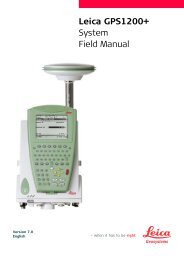
FOREWORDThank you for purchasing the TOPCON Pulse Total Station, <strong>GPT</strong>-<strong>3000</strong> series. Forthe best performance of the instruments, please carefully read these instructionsand keep them in a convenient location for future reference.1
General Handling PrecautionsBefore starting work or operation, be sure to check that the instrument isfunctioning correctly with normal performance.Do not submerge the instrument into water.The instrument can not be submerged underwater.The instrument is designed based on the International Standard IP66, therefore it isprotected from the normal rainfall.Setting the instrument on a tripodWhen mounting the instrument on a tripod, use a wooden tripod when possible. Thevibrations that may occur when using a metallic tripod can effect the measuring precision.Installing the tribrachIf the tribrach is installed incorrectly, the measuring precision could be effected.Occasionally check the adjusting screws on the tribrach. Make sure the base fixing lever islocked and the base fixing screws are tightened.Guarding the instrument against shocksWhen transporting the instrument, provide some protection to minimize risk of shocks.Heavy shocks may cause the measurement to be faulty.Carrying the instrumentAlways carry the instrument by its handgrip.Exposing the instrument to extreme heat.Do not leave the instrument in extreme heat for longer than necessary. It could adverselyaffect its performance.Sudden changes of temperatureAny sudden change of temperature to the instrument or prism may result in a reduction ofmeasuring distance range, i.e when taking the instrument out from a heated vehicle. Letinstrument acclimate itself to ambient temperature.Battery level checkConfirm battery level remaining before operating.Taking the battery outIt is recommended not to take the battery out during the power is on. All the data stored ispossible gone at that time. So please do your assembling or taking the battery out after thepower is off.Noise from the inside of instrumentWhen EDM turns on, the sound of motors from inside the instrument body may beheard. This is normal and does not effect operation of the instrument.2
Display for Safe UseIn order to encourage the safe use of products and prevent any danger to the operator andothers or damage to properties, important warnings are put on the products and inserted in theinstruction manuals.We suggest that everyone understand the meaning of the following displays and icons beforereading the “Safety Cautions” and text.DisplayMeaningIgnoring or disregard of this display may lead to the danger of death orWARNINGserious injury.Ignoring or disregard of this display may lead to personal injury or physicaldamage.CAUTION•Injury refers to hurt, burn, electric shock, etc.•Physical damage refers to extensive damage to buildings or equipment and furniture.Safety CautionsWARNING•There is a risk of fire, electric shock or physical harm if you attempt to disassemble orrepair the instrument yourself.This is only to be carried out by TOPCON or an authorized dealer, only!•Cause eye injury or blindness.Do not look at the sun through a telescope.•Laser beams can be dangerous, and can cause eye injury's if used incorrectly.Never attempt to repair the instrument yourself.•Cause eye injury or blindness.Do not stare into beam.•High temperature may cause fire.Do not cover the charger while it is charging.•Risk of fire or electric shock.Do not use damaged power cable, plug and socket.•Risk of fire or electric shock.Do not use a wet battery or charger.•May ignite explosively.Never use an instrument near flammable gas, liquid matter, and do not use in a coal mine.•Battery can cause explosion or injury.Do not dispose in fire or heat.•Risk of fire or electric shock.Do not use any power voltage except the one given on manufacturers instructions.•Battery can cause outbreak of fire.Do not use any other type of charger other than the one specified.•Risk of fire.Do not use any other power cable other than the one specified.•The short circuit of a battery can cause a fire.Do not short circuit battery when storing it.3
CAUTION•Use of controls or adjustment or performance of procedures other than those specified hereinmay result in hazardous radiation exposure.•Let the laser beam reach the aimed object or the target without anybody else in the laser beampath. In case you operate laser beam open, avoid radiating laser beam to the height of man'shead. It is quite possible for the beam to enter into one's eyes, and it is possible to lose visualsight temporarily, and lose one's caution and awareness of other dangers - avoid glaring beam.•Do not connect or disconnect equipment with wet hands, you are at risk of electric shocks if youdo!•Risk of injury by overturn the carrying case.Do not stand or sit on the carrying cases.•Please note that the tips of tripod can be hazardous, be aware of this when setting up or carryingthe tripod.•Risk of injury by falling down the instrument or case.Do not use a carrying case with a damaged which belts, grips or latches.•Do not allow skin or clothing to come into contact with acid from the batteries, if this does occurthen wash off with copious amounts of water and seek medical advice.•A plumb bob can cause an injury to a person if used incorrectly.•It could be dangerous if the instrument falls over, please ensure you attach a hand grip to theinstrument securely.•Ensure that you mount the Tribrach correctly, failing to do so may result in injury if the tribrachwere to fall over.•It could be dangerous if the instrument falls over, please check that you fix the instrument tothe tripod correctly.•Risk of injury by falling down a tripod and an instrument.Always check that the screws of tripod are tightened.User1)This product is for professional use only!The user is required to be a qualified surveyor or have a good knowledge of surveying, in order tounderstand the user and safety instructions, before operating, inspecting or adjusting.2)Wear the required protectors (safety shoes, helmet, etc.) when operating.Exceptions from Responsibility1)The user of this product is expected to follow all operating instructions and make periodic checks of theproduct’s performance.2)The manufacturer, or its representatives, assumes no responsibility for results of a faulty or intentionalusage or misuse including any direct, indirect, consequential damage, and loss of profits.3)The manufacturer, or its representatives, assumes no responsibility for consequential damage, andloss of profits by any disaster, (an earthquake, storms, floods etc.).A fire, accident, or an act of a third party and/or a usage any other usual conditions.4)The manufacturer, or its representatives, assumes no responsibility for any damage, and loss of profitsdue to a change of data, loss of data, an interruption of business etc., caused by using the product oran unusable product.5)The manufacturer, or its representatives, assumes no responsibility for any damage, and loss of profitscaused by usage except for explained in the user manual.6)The manufacturer, or its representatives, assumes no responsibility for damage caused by wrongmovement, or action due to connecting with other products.4
Laser Safety● Distance Measurement<strong>GPT</strong>-<strong>3000</strong> series uses the invisible laser beam. The <strong>GPT</strong>-<strong>3000</strong> series are manufactured and sold inaccordance with "Performance Standards for Light-Emitting Products" (FDA/BRH 21 CFR 1040) or"Radiation Safety of Laser Products, Equipment Classification, Requirements and User`s Guide" (IECPublication 825) provided on the safety standard for laser beam.As per the said standard, the <strong>GPT</strong>-<strong>3000</strong> series is classified as "Class 1 (l) Laser Products".In case of any failure, do not disassemble the instrument. Contact TOPCON or your TOPCON dealer.● Laser pointer and Plumb Laser (Plumb laser is supplied for certain markets)<strong>GPT</strong>-<strong>3000</strong> series plumb laser and laser pointer use the visible laser beam. The <strong>GPT</strong>-<strong>3000</strong> series plumblaser and laser pointer are manufactured and sold in accordance with "Performance Standards forLight-Emitting Products" (FDA/BRH 21 CFR 1040) or "Radiation Safety of Laser Products, EquipmentClassification, Requirements and User`s Guide" (IEC Publication 825) provided on the safety standardfor laser beam.As per the said standard, the <strong>GPT</strong>-<strong>3000</strong> series plumb laser type is classified as "Class 2 (II) LaserProducts".In case of any failure, do not disassemble the instrument. Contact TOPCON or your TOPCON dealer.LabelsFind the labels which describes the caution and safety about the laser beam as follows in <strong>GPT</strong>-<strong>3000</strong>series.We request you to replace it one anytime the caution labels are damaged or lost and paste a new oneat the same place. You can get the labels from Topcon or your dealer.Warning LabelLaser apertureExplanatory LabelCAUTIONLASER RADIATIONDO NOTSTARE INTO BEAMWAVE LENGTH 620nm-690nm1mW MAXIMUM OUTPUTCLASS II LASER PRODUCTAperture LabelAVOID EXPOSURELASER LIGHT IS EMITTEDFROM THIS APERTURELaser aperture(Only for laser plummet type.)LASER RADIATIONDO NOT STARE INTO BEAMMaximum output 1 W @ Wave length 690nm CWCLASS 2 @LASER PRODUCTSymbol mark while the laser is emitting.The following symbol mark will appear at theright side of the second line.TILT SENSOR:[XY-ON]X:-0°00'25"Y: 0°00'20"X-ON XY-ON OFF L.PLSymbol mark5
ContentsFOREWORD . . . . . . . . . . . . . . . . . . . . . . . . . . . . . . . . . . . . . . . . . . . . . . . . . . 1General Handling Precautions . . . . . . . . . . . . . . . . . . . . . . . . . . . . . . . . . . . . . . . . . . . . . . . 2Display for Safe Use . . . . . . . . . . . . . . . . . . . . . . . . . . . . . . . . . . . . . . . . . . . . . . . . . . . . . . 3Safety Cautions . . . . . . . . . . . . . . . . . . . . . . . . . . . . . . . . . . . . . . . . . . . . . . . . . . . . . . . . . . . . 3User. . . . . . . . . . . . . . . . . . . . . . . . . . . . . . . . . . . . . . . . . . . . . . . . . . . . . . . . . . . . . . . . . . . . . 4Exceptions from Responsibility . . . . . . . . . . . . . . . . . . . . . . . . . . . . . . . . . . . . . . . . . . . . . . . . 4Laser Safety . . . . . . . . . . . . . . . . . . . . . . . . . . . . . . . . . . . . . . . . . . . . . . . . . . . . . . . . . . . . . . 5Labels . . . . . . . . . . . . . . . . . . . . . . . . . . . . . . . . . . . . . . . . . . . . . . . . . . . . . . . . . . . . . . . . . . . 5Symbol mark while the laser is emitting.. . . . . . . . . . . . . . . . . . . . . . . . . . . . . . . . . . . . . . . . . 5Standard Set Composition . . . . . . . . . . . . . . . . . . . . . . . . . . . . . . . . . . . . . . . . . . . . . . . . . . . 91 NOMENCLATURE AND FUNCTIONS. . . . . . . . . . . . . . . . . . . . . . . . . . . 1-11.1 Nomenclature. . . . . . . . . . . . . . . . . . . . . . . . . . . . . . . . . . . . . . . . . . . . . . . . . . . . . . . . 1-11.2 Display . . . . . . . . . . . . . . . . . . . . . . . . . . . . . . . . . . . . . . . . . . . . . . . . . . . . . . . . . . . . . 1-31.3 Operating Key . . . . . . . . . . . . . . . . . . . . . . . . . . . . . . . . . . . . . . . . . . . . . . . . . . . . . . . 1-41.4 Function Key (Soft Key) . . . . . . . . . . . . . . . . . . . . . . . . . . . . . . . . . . . . . . . . . . . . . . . . 1-51.5 Star key mode . . . . . . . . . . . . . . . . . . . . . . . . . . . . . . . . . . . . . . . . . . . . . . . . . . . . . . . 1-71.6 Serial signal RS-232C connector . . . . . . . . . . . . . . . . . . . . . . . . . . . . . . . . . . . . . . . . 1-102 PREPARATION FOR MEASUREMENT . . . . . . . . . . . . . . . . . . . . . . . . . 2-12.1 Power Connection . . . . . . . . . . . . . . . . . . . . . . . . . . . . . . . . . . . . . . . . . . . . . . . . . . . . 2-12.2 Setting Instrument Up For Measurement. . . . . . . . . . . . . . . . . . . . . . . . . . . . . . . . . . . 2-22.3 Power Switch Key ON . . . . . . . . . . . . . . . . . . . . . . . . . . . . . . . . . . . . . . . . . . . . . . . . . 2-32.4 Battery Power Remaining Display . . . . . . . . . . . . . . . . . . . . . . . . . . . . . . . . . . . . . . . . 2-42.5 Vertical and Horizontal Angle Tilt Correction . . . . . . . . . . . . . . . . . . . . . . . . . . . . . . . . 2-52.6 How to Enter Alphanumeric characters . . . . . . . . . . . . . . . . . . . . . . . . . . . . . . . . . . . . 2-72.7 Point Guide . . . . . . . . . . . . . . . . . . . . . . . . . . . . . . . . . . . . . . . . . . . . . . . . . . . . . . . . . 2-82.8 Laser Plummet ON/OFF (Only for Laser Plummet type) . . . . . . . . . . . . . . . . . . . . . . . 2-93 ANGLE MEASUREMENT . . . . . . . . . . . . . . . . . . . . . . . . . . . . . . . . . . . . 3-13.1 Measuring Horizontal Angle Right and Vertical Angle . . . . . . . . . . . . . . . . . . . . . . . . . 3-13.2 Switching Horizontal Angle Right/Left . . . . . . . . . . . . . . . . . . . . . . . . . . . . . . . . . . . . . 3-23.3 Measuring from the Required Horizontal Angle . . . . . . . . . . . . . . . . . . . . . . . . . . . . . . 3-23.3.1 Setting by Holding the Angle. . . . . . . . . . . . . . . . . . . . . . . . . . . . . . . . . . . . . . . . 3-23.3.2 Setting a Horizontal Angle from the Keys . . . . . . . . . . . . . . . . . . . . . . . . . . . . . . 3-33.4 Vertical Angle Percent Grade(%) Mode . . . . . . . . . . . . . . . . . . . . . . . . . . . . . . . . . . . . 3-33.5 Repetition Angle Measurement . . . . . . . . . . . . . . . . . . . . . . . . . . . . . . . . . . . . . . . . . . 3-43.6 Buzzer Sounding for Horizontal Angle 90° Increments . . . . . . . . . . . . . . . . . . . . . . . . 3-53.7 Compasses ( vertical angle). . . . . . . . . . . . . . . . . . . . . . . . . . . . . . . . . . . . . . . . . . . . . 3-64 DISTANCE MEASUREMENT . . . . . . . . . . . . . . . . . . . . . . . . . . . . . . . . . 4-14.1 Setting of the Atmospheric Correction . . . . . . . . . . . . . . . . . . . . . . . . . . . . . . . . . . . . . 4-14.2 Setting of the Correction for Prism Constant / Non-prism Constant. . . . . . . . . . . . . . . 4-14.3 Distance Measurement (Continuous Measurement) . . . . . . . . . . . . . . . . . . . . . . . . . . 4-24.4 Distance Measurement (N-time Measurement/Single Measurement) . . . . . . . . . . . . . . . . . . . 4-34.5 Fine Mode/Tracking Mode/Coarse Mode. . . . . . . . . . . . . . . . . . . . . . . . . . . . . . . . . . . 4-44.6 Stake Out (S.O) . . . . . . . . . . . . . . . . . . . . . . . . . . . . . . . . . . . . . . . . . . . . . . . . . . . . . . 4-54.7 Offset Measurement. . . . . . . . . . . . . . . . . . . . . . . . . . . . . . . . . . . . . . . . . . . . . . . . . . . 4-64.7.1 Angle Offset. . . . . . . . . . . . . . . . . . . . . . . . . . . . . . . . . . . . . . . . . . . . . . . . . . . . . 4-74.7.2 Distance Offset Measurement. . . . . . . . . . . . . . . . . . . . . . . . . . . . . . . . . . . . . . . 4-94.7.3 Plane Offset Measurement . . . . . . . . . . . . . . . . . . . . . . . . . . . . . . . . . . . . . . . . 4-114.7.4 Column Offset Measurement . . . . . . . . . . . . . . . . . . . . . . . . . . . . . . . . . . . . . . 4-135 COORDINATE MEASUREMENT. . . . . . . . . . . . . . . . . . . . . . . . . . . . . . . 5-15.1 Setting Coordinate Values of Occupied Point . . . . . . . . . . . . . . . . . . . . . . . . . . . . . . . 5-15.2 Setting Height of the Instrument. . . . . . . . . . . . . . . . . . . . . . . . . . . . . . . . . . . . . . . . . . 5-25.3 Setting Height of Target (Prism Height) . . . . . . . . . . . . . . . . . . . . . . . . . . . . . . . . . . . . 5-25.4 Execution of Coordinate Measuring. . . . . . . . . . . . . . . . . . . . . . . . . . . . . . . . . . . . . . . 5-36 SPECIAL MODE (Menu Mode) . . . . . . . . . . . . . . . . . . . . . . . . . . . . . . . . 6-16
9.3.3 Deleting a File . . . . . . . . . . . . . . . . . . . . . . . . . . . . . . . . . . . . . . . . . . . . . . . . . . . 9-99.4 Coordinate Data Direct Key Input . . . . . . . . . . . . . . . . . . . . . . . . . . . . . . . . . . . . . . . 9-109.4.1 Coordinate data input. . . . . . . . . . . . . . . . . . . . . . . . . . . . . . . . . . . . . . . . . . . . 9-109.4.2 PTL (Point to Line) data input . . . . . . . . . . . . . . . . . . . . . . . . . . . . . . . . . . . . . . 9-119.5 Delete a Coordinate Data from a File. . . . . . . . . . . . . . . . . . . . . . . . . . . . . . . . . . . . . 9-129.6 Editing PCODE Library . . . . . . . . . . . . . . . . . . . . . . . . . . . . . . . . . . . . . . . . . . . . . . . 9-139.7 Data Communications . . . . . . . . . . . . . . . . . . . . . . . . . . . . . . . . . . . . . . . . . . . . . . . . 9-149.7.1 Sending Data. . . . . . . . . . . . . . . . . . . . . . . . . . . . . . . . . . . . . . . . . . . . . . . . . . . 9-149.7.2 Loading Data . . . . . . . . . . . . . . . . . . . . . . . . . . . . . . . . . . . . . . . . . . . . . . . . . . . 9-159.7.3 Setting Parameter of Data Communications. . . . . . . . . . . . . . . . . . . . . . . . . . . 9-169.8 Initialization . . . . . . . . . . . . . . . . . . . . . . . . . . . . . . . . . . . . . . . . . . . . . . . . . . . . . . . . 9-1710 SET AUDIO MODE. . . . . . . . . . . . . . . . . . . . . . . . . . . . . . . . . . . . . . . . 10-111 SETTING THE PRISM / NON-PRISM CONSTANT VALUE . . . . . . . . 11-112 SETTING ATMOSPHERIC CORRECTION. . . . . . . . . . . . . . . . . . . . . 12-112.1 Calculation of Atmospheric Correction. . . . . . . . . . . . . . . . . . . . . . . . . . . . . . . . . . . 12-112.2 Setting of Atmospheric Correction Value. . . . . . . . . . . . . . . . . . . . . . . . . . . . . . . . . 12-113 CORRECTION FOR REFRACTION AND EARTH CURVATURE. . . . 13-113.1 Distance Calculation Formula . . . . . . . . . . . . . . . . . . . . . . . . . . . . . . . . . . . . . . . . . 13-114 POWER SOURCE AND CHARGING. . . . . . . . . . . . . . . . . . . . . . . . . . 14-114.1 On-board Battery BT-52QA . . . . . . . . . . . . . . . . . . . . . . . . . . . . . . . . . . . . . . . . . . . 14-115 DETACH/ATTACH OF TRIBRACH . . . . . . . . . . . . . . . . . . . . . . . . . . . 15-116 SELECTING MODE . . . . . . . . . . . . . . . . . . . . . . . . . . . . . . . . . . . . . . . 16-116.1 Items of the Selecting Mode. . . . . . . . . . . . . . . . . . . . . . . . . . . . . . . . . . . . . . . . . . . 16-116.2 How to Set Selecting Mode . . . . . . . . . . . . . . . . . . . . . . . . . . . . . . . . . . . . . . . . . . . 16-317 CHECK AND ADJUSTMENT. . . . . . . . . . . . . . . . . . . . . . . . . . . . . . . . 17-117.1 Checking and adjusting of instrument constant . . . . . . . . . . . . . . . . . . . . . . . . . . . 17-117.2 Checking the Optical Axis . . . . . . . . . . . . . . . . . . . . . . . . . . . . . . . . . . . . . . . . . . . . 17-217.2.1 Checking the optical axis of EDM and theodolite . . . . . . . . . . . . . . . . . . . . . . 17-217.2.2 Checking the optical axis of Laser pointer . . . . . . . . . . . . . . . . . . . . . . . . . . . 17-517.3 Checking/Adjusting the Theodolite Functions . . . . . . . . . . . . . . . . . . . . . . . . . . . . . 17-717.3.1 Checking /Adjusting the Plate Level . . . . . . . . . . . . . . . . . . . . . . . . . . . . . . . . 17-817.3.2 Checking /Adjusting the Circular Level . . . . . . . . . . . . . . . . . . . . . . . . . . . . . . 17-817.3.3 Adjustment of the Vertical Cross-hair . . . . . . . . . . . . . . . . . . . . . . . . . . . . . . . 17-917.3.4 Collimation of the Instrument. . . . . . . . . . . . . . . . . . . . . . . . . . . . . . . . . . . . . 17-1017.3.5 Checking / Adjusting the Optical Plummet Telescope. . . . . . . . . . . . . . . . . . 17-1117.3.6 Checking / Adjusting the Laser Plummet (For Laser Plummet type). . . . . . . 17-1217.3.7 Adjustment of Vertical Angle 0 Datum. . . . . . . . . . . . . . . . . . . . . . . . . . . . . . 17-1317.4 How to Set the Instrument Constant Value . . . . . . . . . . . . . . . . . . . . . . . . . . . . . . 17-1417.5 Adjustment of Compensation Systematic Error of Instrument . . . . . . . . . . . . . . . . 17-1517.6 EDM Alignment Checking mode . . . . . . . . . . . . . . . . . . . . . . . . . . . . . . . . . . . . . . 17-1618 PRECAUTIONS . . . . . . . . . . . . . . . . . . . . . . . . . . . . . . . . . . . . . . . . . . 18-119 SPECIAL ACCESSORIES . . . . . . . . . . . . . . . . . . . . . . . . . . . . . . . . . . 19-120 BATTERY SYSTEM . . . . . . . . . . . . . . . . . . . . . . . . . . . . . . . . . . . . . . . 20-121 PRISM SYSTEM. . . . . . . . . . . . . . . . . . . . . . . . . . . . . . . . . . . . . . . . . . 21-122 ERROR DISPLAYS . . . . . . . . . . . . . . . . . . . . . . . . . . . . . . . . . . . . . . . 22-123 SPECIFICATIONS . . . . . . . . . . . . . . . . . . . . . . . . . . . . . . . . . . . . . . . . 23-1APPENDIX ......................................................................................Appendix-1Dual Axis Compensation ........................................................................................ Appendix-1Precaution when Charging or Storing Batteries..................................................... Appendix-38
Standard Set CompositionThe numerical value in parentheses shows the quantity.<strong>GPT</strong>-<strong>3000</strong> series (with lens cap) (1)Plastic carrying case(1)The form of a case will differ depending on a market.On-board Battery BT-52QA (2) Battery charger BC-27BR or BC-27CR (1)Sun shade(1)Plastic rain cover(1)Plumb bob set(1) Tool kit with case (1)[ rod pin, screwdriver, hexagonal wrench, cleaningbrush ]Plumb bob hanger is including in the tool kit case.Instruction manual (1) Siliiconcloth (1)(Make sure that all of the above items are with the instrument when purchased.)Remarks:1) Battery charger BC-27CR is for AC 230V use and BC-27BR is for AC 120V use.2) Plumb bob set and plumb bob hook are supplied for certain markets.3) Additional On-board Battery BT-52QA may be included in some markets.9
1 NOMENCLATURE AND FUNCTIONS1.1 Nomenclature1 NOMENCLATURE AND FUNCTIONSHandgrip locking screwHandgripObjective lensLaser pointerLaser apertureInstrumentcenter markPoint guideDisplay unit(Only for <strong>GPT</strong>-3002/3003/3005)Optical plummettelescope(Optical plummettelescope type only)Circular levelAdjustment screwfor circular levelLeveling screwTribrach fixing leverBase1-1
1 NOMENCLATURE AND FUNCTIONSSighting collimatorTelescope focusing knobBattery locking leverTelescope gripOn-board batteryBT-52QATelescope eyepieceInstrumentcenter mark*Vertical motion clamp*Vertical tangent screwPlate levelHorizontaltangent screwDisplay unitHorizontalmotion clampPower supplyconnectorSerial Signalconnector*The position of vertical motion clamp and Vertical tangent screw will differ depending on the market.1-2
1.2 Display●●●1 NOMENCLATURE AND FUNCTIONSDisplayThe display uses a graphic LCD which has 4 lines and 20 characters per line. In general, the upperthree lines display measured data, and the bottom line displays the soft key function which changeswith the measuring mode.Contrast and IlluminationThe contrast and illumination of display window are adjusted. See Chapter 6 “SPECIAL MODE(Menu Mode)” or section 1.5 “Star key mode”.ExampleV : 90°10'20"HR: 120°30'40"HR: 120°30'40"HD* 65.432 mVD: 12.345 m0SET HOLD HSET P1↓MEAS MODE NP/P P1↓Angle measurement modeDistance measurement modeV-angle : 90°10’20”H-angle : 120°30’40”Feet unitHR: 120°30'40"HD* 123.45 fVD: 12.34 fMEAS MODE NP/P P1↓Horizontal-angle :120°30’40”Horizontal distance : 65.432mRelative elevation :12.345mFeet and inch unitHR: 120°30'40"HD* 123.04.6fVD: 12.03.4fMEAS MODE NP/P P1↓Horizontal-angle : 120°30’40”Horizontal distance : 123.45ftRelative elevation : 12.34ftHorizontal-angle : 120°30’40”Horizontal distance : 123ft4in6/8inRelative elevation : 12ft3in4/8in●Display marksDisplay Contents Display ContentV V-angle ✻ EDM workingHR H-angle right m Meter unitHL H-angle left f Feet unit / Feet and inch unitHD Horizontal distance NP Switches non-prism mode or prism modeVD Relative elevation Laser emitting markSDNEZSlope distanceN coordinateE coordinateZ coordinate1-3
1.3 Operating Key1 NOMENCLATURE AND FUNCTIONSKeys Name of Key FunctionStar keyCoordinatemeas.keyDistance meas.keyStar key mode is used for each presetting or displaying as follows.1 Contrast of the display 2 Reticle illumination 3 Back Light4 Non-prism/Prism 5 Laser pointer 6 Laser plummet7 Tilt correction 8 Point guide 9 Set audio modeCoordinate measurement modeDistance measurement modeANG Angle meas.key Angle measurement modeMENUESCMenu keyEscape keySwitches menu mode and normal mode. To set application measurementsand adjust in the menu mode.● Returning to the measurement mode or previous layer mode from themode set.● To be DATA COLLECTION mode or LAYOUT mode directly from thenormal measurement mode.● It is also possible to use as Record key in normal measurement mode.To select function of Escape key, see Chapter 16 “SELECTING MODE”.ENT Enter key Press at the end of inputting values.POWER Power source key ON/OFF of power sourceF1–F4Soft key( Function key)Responds to the message displayed.1-4
1.4 Function Key (Soft Key)1 NOMENCLATURE AND FUNCTIONSThe Soft Key message is displayed at the bottom line of display. The functions are according to thedisplayed message.Angle measurement modeV: 90°10'20"HR:120°30'40"0SET HOLD HSET P1↓TILT REP V% P2↓H-BZ R/L CMPS P3↓[F1] [F2] [F3] [F4]Soft keysDistance measurement modeHR:120°30'40"HD*[r]
1 NOMENCLATURE AND FUNCTIONSCoordinate measurement mode123F1 MEAS Start measuring.F2 MODE Sets a measuring mode, Fine/Coarse/Tracking.F3 NP/P Switches non-prism mode or prism mode.F4 P1↓ The function of soft keys is shown on next page (P2).F1 R.HT Sets a prism height by input values.F2 INSHT Sets an instrument height by input values.F3 OCC Sets an instrument coordinate point by input values.F4 P2↓ The function of soft keys is shown on next page (P3).F1 OFSET Select Off-set measurement mode.F2 m/f/i Switches meter, feet or feet and inch unit.F3 S/A Select set audio mode.F4 P3↓ The function of soft keys is shown on next page (P1).1-6
1 NOMENCLATURE AND FUNCTIONS1.5 Star key modePress the (★) key to view the instrument options.The following instrument options can be selected from the (★):1.Adjustment the contrast of the display (0 to 9 steps) [or ]2.Adjustment the reticle illumination (1 to 9 steps) [ or ]3.Turn the backlight of the display ON / Blink / OFF4.Select Non-prism mode / Prism mode5.Turn the Laser pointer option ON/OFF6. Turn the Laser plummet option ON/OFF (Only for the laser plummet type)7.Setting Tilt Correction8.Turn the Point Guide option ON/OFF9.S/A (set audio) modeNote: Star key mode does not function when the same function as the function assigned to the star keymode is performed from the main routine.V : 90°10'20"HR : 20°30'40"0SET HOLD HSET P1↓Press the star (★) key.CONT:5 ↕ RTCL:5 ↔B.LT NP/P L.P.L.PLPress the star (★) key.CONT:5 ↕ RTCL:5 ↔--- TILT P.G. S/AkeyDisplaymarkFunctionF1 B.LT Turn the backlight of the display ON/OFFF2 NP/P Non-prism mode / Prism mode selectionF3 L.P. Turn the Laser pointer option ON / Blink / OFFF4 L.PL Turn the Laser plummet option ON/OFF (Only for the laser plummet type)F1 --- ----F2 TILTSetting Tilt CorrectionIf ON, the display shows tilt correction value.F3 P.G. Turn the Point Guide option ON/OFFF4S/AThe light acceptance quantity level for the EDM (SIGNAL), the atmosphericcorrection value (PPM) and correction value of prism constant (PSM) aredisplayed.or CONT Adjust the contrast of the display (0 to 9 steps)orRTCLAdjust the Reticle Illumination (1 to 9 steps)ON/OFF of the reticle illumination is linked with ON/OFF of the backlight.1-7
1 NOMENCLATURE AND FUNCTIONS●●●●●Adjustment the contrast (0 to 9 ) of the display (CONT)This enable you to adjust the contrast of the display.Press the up or down arrow keys to adjust the contrast.Adjustment the reticle illumination (1 to 9 ) (RTCL)This enable you to adjust the reticle illumination.Press the right or left arrow keys to adjust the reticle illumination.Turn the display backlight ON/OFFTo turn the backlight ON, press the [F1] key. Press [F1] again to turn the backlight OFF.Switching the non-purism mode/prism modeTo switch the non-prism /prism mode, press the [F2](NP/P) key. For more information, see Chapter4 “DISTANCE MEASUREMENT” .Lighting, Blinking, and Extinguishing of Laser PointerWhenever the [F3] (L.P.) key is pressed, the laser pointer will light up, blink, or be extinguished, inthat order. The laser pointer assists with collimation by radiating visible laser light from the objectivelens to the target.Laser aperture●●●●●The laser pointer indicates the approximate collimation position of the telescope. It does notindicate the exact collimation position. To adjust the laser pointer, see 17.2.2 “Checking theoptical axis of Laser pointer”.When the EDM is working, the laser pointer will blink.The distance to which the laser pointer can be used will vary with climatic conditions andwith the eyesight of the user.You cannot see the laser pointer when looking through the telescope. Therefore, please lookdirectly, with the naked eye, at the point indicated by the laser pointer.When the laser pointer is used, the operating time of internal power source will becomeshort.●Laser Plummet (Only for Laser Plummet type)Laser plummet option will help you to center theinstrument easily onto the measurement point.Press the star key to view the instrument options.Laser aperture1-8
1 NOMENCLATURE AND FUNCTIONS●Tilt correctionThe tilt setting mode performed here will not be memorized after powering OFF. To set TILTcorrection in the initialized setting (it is memorized after powering OFF), see Section 6.4.3 “Verticaland Horizontal Angle Tilt correction ( Tilt ON/OFF)” .●Point guideFast and simple to use, the Point Guide feature is useful when doing stake out work. The LED’s forthe Point Guide System on the instrument telescope assist the rod person to get on-line. Whenusing the Point Guide System, the battery life will be approximately 8 hours at +20 °C (+68 °F).Turning the Point Guide ON and Operation:Press the [F3] key to turn ON the Point Guide LEDs.Looking at the objective lens of the telescope, the rightLED will blink and the left LED will stay lit.InstrumentThe Point Guide should be used within a distance of 100meters (328 feet). The quality of its results will depend onthe weather conditions and the user’s eyesight.The goal of the rod person is to look at both LED’s on theinstrument and move the prism on-line until both LED’sare equally bright.5If the solid LED is brighter, move right.If the blinking LED is brighter, move left.IlluminateBlinkPrismOnce you have determined that both of the LED's are equally bright, you are on-line with theinstrument.Turning the Point Guide OFF:To turn OFF the Point Guide System, press the [F3] key again.●Set audio modeThe light acceptance quantity level (Signal level) is displayed in this mode.When reflected light from the prism is received, a buzzer sounds. This function is good for easycollimation when the target is difficult to find.Press the [F4] key to view the set audio screen.(1) To stop the buzzer, refer to Chapter 16 “SELECTING MODE”.(2) Also, it is possible to display the signal level in Distance Measuring Mode.The temperature, pressure, PPM, PSM and NPM can be viewed in set audio mode.Refer to Chapter 10 “SET AUDIO MODE”, Chapter 11 “SETTING THE PRISM / NON-PRISMCONSTANT VALUE” and Chapter 12 “ SETTING ATMOSPHERIC CORRECTION”, for furtherinstructions.1-9
1.6 Serial signal RS-232C connector1 NOMENCLATURE AND FUNCTIONSThe serial signal connector is used for connecting the <strong>GPT</strong>-<strong>3000</strong> series with a computer or TOPCONData Collector, which enables the computer to receive measured data from the <strong>GPT</strong>-<strong>3000</strong> series or tosend preset data of horizontal angle, etc. to it.●The following data will be output at each mode.ModeAngle mode ( V,HR or HL) ( V in percent)Horizontal distance mode (HR, HD, VD)Slope distance mode (V, HR,SD)Coordinate modeOutputV,HR (or HL)V,HR, HD, VDV,HR, SD,HDN, E, Z, HR (or V,H,SD,N,E,Z)●●The display and the output at the coarse mode are the same as the contents above.Output at the tracking mode is displayed as distance data only.The details necessary for the connection with the <strong>GPT</strong>-<strong>3000</strong> Series are obtained from its InterfaceManual which is optionally available. Please refer to the manual.1-10
2 PREPARATION FOR MEASUREMENT2.1 Power Connection(unnecessary if on-board Ni-MH battery BT-52QA is used)2 PREPARATION FOR MEASUREMENTSee below for connecting the external battery pack.● Battery pack BT-3QPower cord , PC-5 is used.● Large capacity battery pack BT-3LPower cord PC-6 is used.CableBattery packConnector endsPC-5BT-3QPC-5PC-6BT-3LPC-6Note:BT-32Q on-board (Ni-Cd) battery can be also available.To use BT-32Q (Ni-Cd) battery, it is required to change battery type in selecting mode, seeSection 6.4.5 “Selecting Battery Type”.2-1
2.2 Setting Instrument Up For Measurement2 PREPARATION FOR MEASUREMENTMount the instrument to the tripod. Level and center the instrument precisely to insure the bestperformance. Use tripods with a tripod screw of 5/8 in. diameter and 11 threads per inch, such as theType E TOPCON wide- frame wooden tripod.Reference: Leveling and Centering the Instrument1. Setting up the TripodFirst, extend the extension legs to suitable lengthsand tighten the screws on their midsections.2. Attaching the Instrument on the TripodHeadPlace the instrument carefully on the tripod headand slide the instrument by loosening the tripodscrew. If the plumb bob is positioned right over thecenter of the point, slightly tighten the tripodscrew.3. Roughly Leveling the Instrument by Usingthe Circular Level1 Turn the leveling screws A and B to move thebubble in the circular level. The bubble is nowlocated on a line perpendicular to a linerunning through the centers of the two levelingscrews being adjusted.Leveling screw CLevelingscrew ALeveling screw B2 Turn the leveling screw C to bring the bubbleto the center of the circular level.4. Centering by Using the Plate Level1 Rotate the instrument horizontally by usingthe Horizontal motion/clamp screw and placethe plate level parallel with the line connectingleveling screws A and B, and then bring thebubble to the center of the plate level byturning leveling screws A and B.2 Rotate the instrument 90° (100gon) around itsvertical axis and turn the remaining levelingscrew or C to center the bubble once more.9090°3 Repeat the procedures 1 and 2 for each 90°(100gon) rotation of the instrument and checkwhether the bubble is correctly centered for allfour points.5. Centering by Using the Optical PlummetTelescopeAdjust the eyepiece of the optical plummettelescope to your eyesight.Slide the instrument by loosening the tripodscrew, place the point on the center mark, andthen tighten the tripod screw. Sliding theinstrument carefully not to rotate that allows youto get the least dislocation of the bubble.PointCenter markLeveling screw C6. Completely Leveling the InstrumentLeveling the instrument precisely in a similar wayto 4. Rotate the instrument and check to see thatthe bubble is in the center of the plate levelregardless of telescope direction, then tighten thetripod screw hard.Levelingscrew ALevelingscrew B2-2
2.3 Power Switch Key ON1 Confirm the instrument is leveled.2 PREPARATION FOR MEASUREMENT2 Press the power key..Press the power keyTOPCON <strong>GPT</strong>-<strong>3000</strong>V : 90°10'20"HR: 0°00'00"Battery Power Remaining Display0SET HOLD HSET P1↓●●Confirm the battery power remaining display. Replace with charged battery or charge when batterylevel is low or indicates “Battery empty”. see Section 2.4“Battery Power Remaining Display” .Contrast adjustmentYou can confirm prism constant value (PSM), non-prism constant value (NPM), atmosphericcorrection value (PPM) and you can also adjust the contrast of the display when the instrument isturned on.To display this screen, see Chapter 16 “SELECTING MODE” .CONTRAST ADJUSTMENTPSM: 0.0 PPM 0.0NPM: 0.0↓ ↑ - - - ENTERThis enables you to adjust the brightness by pressing the [F1](↓) or [F2](↑) key.To memorize the setting value after powering off, press [F4](ENTER) key.2-3
2.4 Battery Power Remaining DisplayBattery power remaining display indicates the power condition.2 PREPARATION FOR MEASUREMENTV : 90°10'20"HR: 0°00'00"Measurement is possible.0SET HOLD HSET P1↓Battery power remaining displayThe power is poor. The batteryshould be recharged or replaced.BlinkingOther displays disappear.Measurement is impossible.Need to recharge or replacethe battery.Note: 1 The battery operating time will vary depending on the environmental conditions such asambient temperature, charging time, the number of times of charging and discharging etc.It is recommended for safety to charge the battery beforehand or to prepare spare fullcharged batteries.2 For general usage of the battery, see Chapter 14 “POWER SOURCE AND CHARGING” .3 The battery power remaining display shows the power level regarding to themeasurement mode now operating.The safety condition indicated by the battery power remaining display in the anglemeasurement mode does not necessarily assure the battery’s ability to be used in thedistance measurement mode.It may happen that the mode change from the angle mode to the distance mode will stopthe operation because of insufficient battery power for the distance mode whichconsumes more power than angle mode.2-4
2.5 Vertical and Horizontal Angle Tilt Correction(<strong>GPT</strong>-3007 has vertical angle tilt correction only.)2 PREPARATION FOR MEASUREMENTWhen the tilt sensors are activated, automatic correction of vertical and horizontal angle formislevelment is displayed.To ensure a precise angle measurement, tilt sensors must be turned on. The display can also be usedto fine level the instrument. If the (TILT OVER) display appears the instrument is out of automaticcompensation range and must be leveled manually.ZenithZenithStanding axisInclination of the standingaxis in the X directionStanding axisInclination of the standingaxis in the Y directionHorizontalTrunnion axis●●<strong>GPT</strong>-<strong>3000</strong> compensates both the vertical angle and the horizontal angle readings due to inclinationof the standing axis in the X and Y directions .For more information about dual axis compensation, refer to APPENDIX 1 “Dual AxisCompensation”.When the instrument is out of compensation. (TILT OVER)V : ° ' "HR: ° ' "Standing Axis in the X directionout of rangeV : ° ' "HR: ° ' "Standing Axis in the Y directionout of rangeV : ° ' "HR: ° ' "Standing Axis in the X and Ydirections out of range●●The display of Vertical or Horizontal angle is unstable when instrument is on an unstable stage or awindy day. You can turn off the auto tilt correction function of V/H angle in this case.To set auto tilt correction from the moment that power is on, see Section 6.4.3“Vertical andHorizontal Angle Tilt correction ( Tilt ON/OFF)” .2-5
●2 PREPARATION FOR MEASUREMENTSetting Tilt Correction by Soft KeyTo enable you to select tilt ON/OFF function. setting is not memorized after power is OFF.[Example] Setting X,Y Tilt OFFOperating procedure Option Display1 Press [F4] key to get the function page 2. [F4]V : 90°10'20"HR: 120°30'40"2 Press [F1](TILT) key.In case ON is already selected, the display showstilt correction value.[F1]0SET HOLD HSET P1↓TILT REP V% P2↓TILT SENSOR:[XY-ON]X:-0°00'25"Y: 0°00'20"X-ON XY-ON OFF ---3 Press [F3](OFF) key. [F3]TILT SENSOR: [OFF]X-ON XY-ON OFF ---4 Press [ESC] key. [ESC]V : 90°10'20"HR: 120°30'40"TILT REPV% P2↓●The setting mode performed here will not be memorized after powering OFF. To set TILT correction inthe initialized setting ( it is memorized after powering OFF), see Section 6.4.3“Vertical and HorizontalAngle Tilt correction ( Tilt ON/OFF)” .2-6
2.6 How to Enter Alphanumeric characters2 PREPARATION FOR MEASUREMENTThis enables you to enter alphanumeric characters such as the instrument height, prism height,occupied point, backsight point etc..● How to select a item[Example setting] Occupied point in the data collection mode.The arrow indicates a item to enter.The arrow line moves up or down when the[ ] key or [ ] key is pressed.PT# →ST-01ID :INS.HT: 0.000 mINPUT SRCH REC OCNEZ[ ]or[ ]PT# :ST-01ID →INS.HT: 0.000 mINPUT SRCH REC OCNEZPT# :ST-01ID :INS.HT→ 0.000 mINPUT SRCH REC OCNEZ● How to enter characters1 Move the arrow to enter a item using th e []or [ ] key.2 Press the [F1] (INPUT) key.The arrow changes to the equal (=) .The characters are displayed on the bottomline.3 Press the [ ] or [ ] key to select a page.PT# →ID :INS.HT: 0.000 mINPUT SRCH REC OCNEZPT# =ID :INS.HT: 0.000 m1234 5678 90.- [ENT]ABCD EFGH IJKL [ENT]MNOP QRST UVWX [ENT]YZ+#[SPC][CLR][ENT][F1] [F2] [F3] [F4]4 Press the soft key to select a group ofcharacters.Example: [F2](QRST) key is pressed.PT# =ID :INS.HT: 0.000 m(Q) (R) (S) (T)[F1] [F2] [F3] [F4]2-7
2 PREPARATION FOR MEASUREMENT5 Press soft key to select a character.Example: [F4](T) key is pressed.Select next character in the same manner.6 Press [F4](ENT) key.The arrow moves to next item.Select next character in the same manner.PT# =TID :INS.HT: 0.000 mMNOP QRST UVWX [ENT]PT# =TOPCON-1ID :INS.HT : 0.000 mMNOP QRST UVWX [ENT]PT# :TOPCON-1ID →INS.HT : 0.000 mINPUT SRCH REC OCNEZ● To correct a character, move the cursor to correct character by pressing [ ] or [ ] key and enteragain.2.7 Point GuideFast and simple to use, the Point Guide feature is useful when doing stake out work. The LED’s for thePoint Guide System on the instrument telescope assist the rod person to get on-line. When using thePoint Guide System, the battery life will be approximately 8 hours at +20 °C (+68 °F).Turning the Point Guide ON and Operation:Press the [MENU] key to get the menu screen and press the[MENU] key again. Point Guide LED’s will be turned ON.Looking at the objective lens of the telescope, the right LEDwill blink and the left LED will stay lit.You can also possible to turn on/off from star key option.The Point Guide should be used within a distance of 100meters (328 feet). The quality of its results will depend on theweather conditions and the user’s eyesight.The goal of the rod person is to look at both LED’s on theinstrument and move the prism on-line until both LED’s areequally bright.●●If the solid LED is brighter, move right.If the blinking LED is brighter, move left.IlluminateInstrumentBlinkPrismOnce you have determined that both of the LED's are equally bright, you are on-line with theinstrument.Turning the Point Guide OFF:To turn OFF the Point Guide System, press the [MENU] key again in menu screen.The point guide function can be available while executing Layout mode. See 8.2 “Executing a Layout”.2-8
2 PREPARATION FOR MEASUREMENT2.8 Laser Plummet ON/OFF (Only for Laser Plummet type)Laser plummet option will help you to center the instrument easily onto the measurement point.There are two ways to turn on/off of laser plummet option as follows.● On/Off of laser plummet option by Soft Key in Tilt CorrectionOperating procedure Option Display1 Press the [F4] key to get the function page 2. [F4]V : 90°10'20"HR: 120°30'40"2 Press the [F1](TILT) key.In case ON is already selected, the display showstilt correction value.3 Press the [F4](L.PL) key.By pressing the [F4](L.PL) key, the laser plummetwill be turned On / Off alternately.[F1][F4]0SET HOLD HSET P1↓TILT REP V% P2↓TILT SENSOR:[XY-ON]X:-0°00'25"Y: 0°00'20"X-ON XY-ON OFF L.PLTILT SENSOR:[XY-ON]X:-0°00'25"Y: 0°00'20"X-ON XY-ON OFF L.PL●Symbol mark while the laser is emitting.The following symbol mark will appear at the right side of the second line.TILT SENSOR:[XY-ON]X:-0°00'25"Y: 0°00'20"Symbol markX-ON XY-ON OFF L.PL●On/Off of laser plummet option from MENU modeOperating procedure Operation Display1 Press the [MENU] key. [MENU]2 Press the [F4](P↓) key to get the menu on page 2. [F4]3 Press the [F3] key. [F3]MENU 1/3F1:DATA COLLECTF2:LAYOUTF3:MEMORY MGR. P↓MENU 2/3F1:PROGRAMSF2:GRID FACTORF3:LASER PLUMMET P↓LASER PLUMMET [OFF]F1:ONF2:OFF4 Press the [F1] or [F2] key to turn on or off the laserplummet option.[F1] or [F2]LASER PLUMMET [ON]F1:ONF2:OFFLaser Plummet auto-cut off functionThe laser plummet will be turned off automatically after 1 to 99 minutes (Default :3 minutes). It is alsopossible to stop the auto-cut off function.Refer to Chapter 16 “SELECTING MODE” to change the time or to invalidate the function.2-9
3 ANGLE MEASUREMENT3 ANGLE MEASUREMENT3.1 Measuring Horizontal Angle Right and Vertical AngleMake sure the mode is in Angle measurement.Operating procedure Operation Display1 Collimate the 1st target (A). Collimate AV : 90°10'20"HR: 120°30'40"2 Set horizontal angle of target A at 0° 00' 00".Press the [F1](0 set) key and press the [F3](YES)key.3 Collimate the 2nd target (B).The required V/H angle to target B will bedisplayed.[F1][F3]Collimate B0SET HOLD HSET P1↓H ANGLE 0 SET> OK?--- --- [YES][NO]V : 90°10'20"HR: 0°00'00"0SET HOLD HSET P1↓V : 98°36'20"HR: 160°40'20"0SET HOLD HSET P1↓Reference : How to Collimate1 Point the telescope toward the light. Turn the diopter ring and adjust the diopter so that the crosshairs are clearly observed.(Turn the diopter ring toward you first and then backward to focus.)2 Aim the target at the peak of the triangle mark of the sighting collimator. Allow a certain spacebetween the sighting collimator and yourself for collimating.3 Focus the target with the focusing knob.*If parallax is created between the crosshairs and the target when viewingvertically or horizontally while lookinginto the telescope, focusing is incorrector diopter adjustment is poor. Thisadversely affects precision inmeasurement or survey Eliminate theparallax by carefully focusingand using diopter adjustment.ÅáÅáFocusing knobTelescope eyepiece (Diopter ring)ÅáÅá3-1
3.2 Switching Horizontal Angle Right/LeftMake sure the mode is Angle measurement.3 ANGLE MEASUREMENTOperating procedure Operation Display1 Press the [F4](↓) key twice to get the functionon page 3.[F4]twiceV : 90°10'20"HR: 120°30'40"0SET HOLD HSET P1↓TILT REP V% P2↓H-BZ R/L CMPS P3↓2 Press the [F2](R/L) key.The mode Horizontal angle Right (HR)switches to (HL) mode.3 Measure as HL mode.[F2]V : 90°10'20"HL: 239°29'20"H-BZR/L CMPS P3↓●Every time pressing the [F2](R/L) key, HR/HL mode switches.3.3 Measuring from the Required Horizontal Angle3.3.1 Setting by Holding the AngleMake sure the mode is angle measurement.Operating procedure Operation Display1 Set the required horizontal angle, usingHorizontal tangent screwDisplay angleV : 90°10'20"HR: 130°40'20"0SET HOLD HSET P1↓2 Press the [F2](HOLD) key. [F2]H ANGLE HOLDHR= 130°40'20"> SET ?--- --- [YES][NO]3 Collimate the target. Collimate4 Press the [F3](YES) key to finish holding thehorizontal angle.*1)The display turns back to normal anglemeasurement mode.[F3]V : 90°10'20"HR: 130°40'20"0SET HOLD HSET P1↓*1) To return to the previous mode, press the [F4](NO) key.3-2
3 ANGLE MEASUREMENT3.3.2 Setting a Horizontal Angle from the KeysMake sure the mode is Angle measurement.Operating procedure Operation Display1 Collimate the target. CollimateV : 90°10'20"HR: 170°30'20"0SET HOLD HSET P1↓2 Press the [F3](HSET) key. [F3]H ANGLE SETHR:3 Input the required horizontal angle byusing keys. *1)For example :70°40'20"When completed, normal measuring from therequired Horizontal angle is possible.[F1]70.4020[F4]INPUT --- --- ENTER1234 5678 90.-[ENT]V : 90°10'20"HR: 70°40'20"0SET HOLD HSET P1↓*1) To enter Alphanumeric characters, see Section 2.6 “ How to Enter Alphanumeric characters” .3.4 Vertical Angle Percent Grade(%) ModeMake sure the mode is Angle measurement.Operating procedure Operation Display1 Press the [F4](↓) key to get the function on page 2. [F4]V : 90°10'20"HR: 170°30'20"0SET HOLD HSET P1↓TILT REP V% P2↓2 Press the [F3](V%) key. *1) [F3]V : -0.30 %HR: 170°30'20"TILT REP V% P2↓*1) Every time pressing the [F3](V%) key, the display mode switches.● When the measurement is carried out over ±45° (±100%) from the horizontal, the display shows.3-3
3.5 Repetition Angle Measurement3 ANGLE MEASUREMENT● Repetition angle measurement can be done by horizontal angle right measurement mode.Make sure the mode is Horizontal Angle Right measurement.Operating procedure Operation Display1 Press the [F4](↓) key to get the function on page 2. [F4]V : 90°10'20"HR: 170°30'20"0SET HOLD HSET P1↓TILT REP V% P2↓2 Press the [F2](REP)key. [F2]REPETITION ANGLE> OK?--- --- [YES][NO]3 Press the [F3](YES) key. [F3]REP-ANGLE COUNT[ 0]Ht: 0°00'00"Hm:0SET V/H REL HOLD4 Collimate the target A and press the [F1] (0SET)key.Collimate A[F1]REPETITION ANGLEINITIALIZE> OK?--- --- [YES][NO]5 Press the [F3] (YES) key. [F3]REP-ANGLE COUNT[ 0]Ht: 0°00'00"Hm:0SET V/H REL HOLD6 Collimate the target B using the horizontal clampand tangent screw.Press the [F4](HOLD) key.7 Recollimate target A using the horizontal clampand tangent screw, and press the [F3](REL)key.8 Recollimate target B using the horizontal clampand tangent screw, and press the [F4](HOLD) key.Collimate B[F4]Collimate A[F3]Collimate B[F4]REP-ANGLE COUNT[ 1]Ht: 45°10'00"Hm: 45°10'00"0SET V/H REL HOLDREP-ANGLE COUNT[ 1]Ht: 45°10'00"Hm: 45°10'00"0SET V/H REL HOLDREP-ANGLE COUNT[ 2]Ht: 90°20'00"Hm: 45°10'00"0SET V/H REL HOLD9 Repeat 7 to 8 to measure the desired number ofrepetitions.REP-ANGLE COUNT[ 4]Ht: 180°40'00"Hm: 45°10'00"0SET V/H REL HOLD[Example] 4 measurement3-4
3 ANGLE MEASUREMENT10 To return to the normal angle mode, press the[F2](V/H) key or [ESC] key.[ESC]or[F2]REPETITION ANGLEExit> OK?--- --- [YES][NO]11 Press the [F3](YES) key. [F3]V : 90°10'20"HR: 170°30'20"● Horizontal angle can be accumulated up to(3600°00'00" – minimum reading) (horizontal angle right).In case of 5 second reading, horizontal angle can be accumulated up to +3599°59'55".● Error will be displayed when the results differ from first measurement by more than ±30".3.6 Buzzer Sounding for Horizontal Angle 90° IncrementsWhen the horizontal angle falls in the range of less than ± 1° of 0°, 90°, 180° or 270°, the buzzersounds. Buzzer stops only when the horizontal angle is adjusted to 0°00’00”, 90°00’00” , 180°00’00” or270°00’00”.This setting is not memorized after powering off. Refer to 16 “SELECTING MODE” to set the initialsetting (memorized after powering off).Make sure the mode is Angle measurement.Operating procedure Operation Display1 Press the [F4](↓) key twice to get the functionon page 3.[F4]twice0SET HOLD HSET P1↓V : 90°10'20"HR: 170°30'20"0SET HOLD HSET P1↓H-BZ R/L CMPS P3↓2 Press the [F1](H-BZ) key.The data previously set is shown.[F1]H-ANGLE BUZZER [OFF]3 Press the [F1](ON) key or [F2](OFF) key to selectthe buzzer ON/OFF.[F1] or [F2][ON] [OFF] --- ENTERH-ANGLE BUZZER [ON][ON] [OFF] --- ENTER4 Press the [F4](ENTER) key. [F4]V : 90°10'20"HR: 170°30'20"0SET HOLD HSET P1↓3-5
LOCK3.7 Compasses ( vertical angle)Vertical angle is displayed as shown below.3 ANGLE MEASUREMENT+90°0° 0°-90°Operating procedure Operation Display1 Press the [F4](↓) key twice to get the functionon page 3.[F4]twiceV : 98°10'20"HR: 170°30'20"0SET HOLD HSET P1↓H-BZ R/L CMPS P3↓2 Press the [F3](CMPS) key. *1) [F3]V : - 8°10'20"HR: 170°30'20"H-BZ R/L CMPS P3↓*1) Every time pressing the [F3](CMPS) key, the display mode switches.3-6
4 DISTANCE MEASUREMENT4 DISTANCE MEASUREMENTNote:Those distance shorter than 1m and 400m or more will not be displayed in Non-prismmode.● Prism mode and Non-prism modeIn <strong>GPT</strong>-<strong>3000</strong> series, the distance measurement will be done using invisible pulse laser beam emittedfrom pulse laser diode. You can select measurement mode between Prism mode which collimating aprism and Non-prism mode that is collimating a target object except prism.●●●●●Regardless of whether the laser pointer is used, measurement is possible with both the non-prismmode and the prism mode. That is, when the <strong>GPT</strong>-<strong>3000</strong> is used in the open air, in an urban area,etc., the laser pointer can be stopped and distance measurement then conducted, making itpossible to prevent the laser light from hitting a third party.When using a reflection sheet, measure with the prism mode.For measurement with a prism, be sure to measure with the prism mode. If you measure with thenon-prism mode, accuracy cannot be guaranteed.Non-prism mode enables all distance measurements such Distance measurement, Coordinatemeasurement, Offset measurement and Layout.To switch over Prism mode to Non-prism mode or contrary, press the [NP/P] soft key in eachmeasurement display. [NP] of Non-prism mode indicator will be shown at the right corner of thedisplay in Non-prism mode measurement.Changing mode shall be done before measurement.ExampleDistance measurement modeHR: 120°30'40"HD* 65.432 mNPVD: 12.345 mMEAS MODE NP/P P1↓Non-prismmodeindicatorCoordinate measurement modeN: 120.456 mE: 34.567 mNPZ: 12.345 mMEAS MODE NP/P P1↓To change the mode, press the [NP/P] soft key in each measurement.●●It is possible to set Non-prism mode for distance measurement during the power on time. Refer to16.SELECTING MODE to set the option.If happened collimating the near distance prism in Non-prism mode, measurement will not be donebecause of too much light.4.1 Setting of the Atmospheric CorrectionWhen setting the atmospheric correction, obtain the correction value by measuring the temperatureand pressure. Refer to Section 12.2 “Setting of Atmospheric Correction Value”.4.2 Setting of the Correction for Prism Constant / Non-prism ConstantTopcon’s prism constant value is 0. Set correction for prism at 0. If the prism is of another manufacture,the appropriate constant shall be set beforehand. Refer to Chapter 11 “SETTING THE PRISM / NON-PRISM CONSTANT VALUE”. The setting value is kept in the memory even after power is off.Note:Confirm that Non-prism correction value is set at zero before measurement target suchas a wall in Non-prism mode.4-1
4.3 Distance Measurement (Continuous Measurement)4 DISTANCE MEASUREMENTMake sure the mode displays angle measurement.Operating procedure Operation Display1 Collimate the center of prism. Collimate PV : 90°10'20"HR: 120°30'40"2 Press the [ ] key.Distance measurement starts. *1),2)[ ]0SET HOLD HSET P1↓HR: 120°30'40"HD*[r]
4 DISTANCE MEASUREMENT4.4 Distance Measurement (N-time Measurement/Single Measurement)When the number of times measurement is preset, the <strong>GPT</strong>-<strong>3000</strong> series measures the distance the setnumber of times. The average distance will be displayed.When presetting the number of times as 1, it does not display the average distance, because of singlemeasurement. Single measurement is set at the factory.Make sure the mode displays angle measurement.Operating procedure Operation Display1 Collimate the center of prism.V : 90°10'20"HR: 120°30'40"0SET HOLD HSETP1↓2 Press the [ ] key.Continuous measuring starts.*1)3 Press [F1](MEAS) key while continuousmeasuring is exceeding. *2)●The average value is displayed and "*" markdisappears.While EDM is working, press [F1](MEAS) keyagain, the mode will be changed to continuousmeasuring mode.[ ][F1]HR: 120°30'40"HD*[r]
4 DISTANCE MEASUREMENT● Choose meter /feet / feet+inch unit by soft keyIt is possible to change the unit for distance measurement mode by soft key.This setting is not memorized after power off. Refer to 16 “SELECTING MODE” to set at the initialsetting (memorized after power off).Operating procedure Operation Display1 Press the [F4](P1↓) key twice to get the functionon page 3.[F4]HR: 120°30'40"HD* 2.000 mVD: 3.000 mMEAS MODE NP/P P1↓OFSET S.O S/AP2↓2 Every time pressing the [F2](m/f/i) key, the displayunit will be changed.● Every time pressing the [F2](m/f/i) key, the unitmode switches.[F2]--- m/f/i --- P3↓HR: 120°30'40"HD* 6.560 fVD: 9.845 f--- m/f/i --- P3↓4.5 Fine Mode/Tracking Mode/Coarse ModeThis setting is not memorized after power is off. Refer to Chapter 16”SELECTING MODE” to set at theinitial setting (memorized after power is off).•Fine Mode•Tracking Mode•Coarse Mode: This is a normal distance measuring mode.The unit to be displayed can be changed.Measurement time will vary depending on the unit to be displayed.: This mode measures in shorter time than in fine mode.It is very useful when tailing the moving object or carrying out stake-out work.: This mode measures in shorter time than in fine mode.The unit to be displayed can be changed.To change the unit to be displayed in fine mode, see Chapter 16 “ SELECTING MODE” and to changethe unit in course mode, see section 6.4.1 “Setting Minimum Reading”.For the details of the unit and measurement time in each mode, see Chapter 23 “SPECIFICATIONS”.Operating procedure Operation DisplayHR: 120°30'40"HD* 123.456mVD: 5.678mMEAS MODE NP/P P1↓1 Press the [F2](MODE) key from the distancemeasuring mode.*1)The initial character (F/T/C) of set mode isdisplayed . (F:Fine, T:Tracking, C:Coarse)2 Press the [F1](FINE) key, [F2](TRACK) key, or[F3](COARSE) key.[F2][F1]~[F3]HR: 120°30'40"HD* 123.456mVD: 5.678mFINE TRACK COARSE FHR: 120°30'40"HD* 123.456mVD: 5.678mMEAS MODE NP/P P1↓*1) To cancel the setting, press the [ESC] key.4-4
4.6 Stake Out (S.O)4 DISTANCE MEASUREMENTThe difference between the measured distance and the input stake out distance is displayed.Measured distance — Stake out distance = Displayed value● In stake out operation, you can select either horizontal distance (HD), relative elevation (VD) andslope distance (SD)Operating procedure Operation Display1 Press the [F4](↓) key in the distance measuring [F4] HR: 120°30'40"mode to get the function on page 2.HD* 123.456 mVD: 5.678 mMEAS MODE NP/P P1↓OFSET S.O S/AP2↓2 Press the [F2](S.O) key.The data previously set is shown.[F2]STAKE OUTHD : 0.000 mHD VD SD ---3 Select the measuring mode by pressing the [F1] to[F3] key.Example : Horizontal distance[F1]4 Enter the distance for stake out. *1) [F1]Enter data[F4]STAKE OUTHD : 0.000 mINPUT --- --- ENTER1234 5678 90.-[ENT]STAKE OUTHD : 100.000 m5 Collimate the target (Prism).Measuring starts.Collimate PINPUT --- --- ENTERHR: 120°30'40"dHD*[r]
4.7 Offset Measurement4 DISTANCE MEASUREMENTThere are four offset measurement modes in the Offset Measurement.● Angle offset● Distance offset● Plane offset● Column offsetTo show the offset measurement menu, press the [OFSET] soft key from distance or coordinatemeasurement mode.Example:Distance measurementHR: 120°30'40"HD: 123.456 mVD: 5.678 mMEAS MODE NP/P P1↓OFSET S.O S/APress the [F1](OFSET) key.P2↓Coordinate measurementN: 123.456 mE: 34.567 mZ: 78.912 mMEAS MODE NP/P P1↓R.HT INSHT OCC P2↓OFSET m/f/i S/A P3↓Press the [F1](OFSET) key.Offset Measurement MenuOFFSET 1/2F1:ANG.OFFSETF2:DIST.OFFSETF3:PLANE OFFSET P↓[F4]OFFSET 2/2F1:COLUMN OFFSETP↓● Outputting the Measurement DataThe results of offset measurement can be output to external device.Setting the function of the [ESC] key to (REC), the [F3] soft key which assigned (REC) will appear inmeasured result display.Refer to Chapter 16 “SELECTING MODE” to set this option.OFFSET-MEASUREMENTHR: 120°30'40"SD: 123.456 mNEXT --- REC ---[F3]● Distance measurement mode of the offset measurementOffset measurement will be done by N-time fine measurement mode.For setting measuring times refer to Chapter 16 “SELECTING MODE”.4-6
4 DISTANCE MEASUREMENT4.7.1 Angle OffsetThis mode is useful when it is difficult to set up the prism directly, for example at the center of a tree.Place the prism at the same horizontal distance from the instrument as that of point A0 to measure.To measure the coordinates of the center position, operate the offset measurement after setting theinstrument height/prism height.When measuring coordinates of ground point A 1:Set the instrument height/prism height.Prism PWhen measuring coordinates of point A 0 : Setthe instrument height only. (Set the prism heightto 0 ).Prism heightInstrument heightWhen sighting to A 0 , you can select one of twoways. One is to fix vertical angle to the prismposition even updown the telescope position, andthe other is to gear vertical angle to the updown oftelescope movement. In case following thevertical angle to the movement of telescope,SD(Slope Distance) and VD(Vertical Distance)will be changed according to the movement oftelescope.To set this option, refer to Chapter 16“SELECTING MODE”.Occ. Point●●Set the instrument height/prism height before proceeding to the offset measurement mode.When setting the coordinate value for the occupied station, refer to Section 5.1 “Setting CoordinateValues of Occupied Point”.Operating procedure Operation Display1 Press the [F4](P1↓) key from distance measuring [F4] HR: 120°30'40"mode to get the function on page 2.HD: 123.456 mVD: 5.678 mMEAS MODE NP/P P1↓OFSET S.O S/A P2↓2 Press the [F1](OFSET) key. [F1]3 Press the [F1](ANG. OFFSET) key. [F1]4 Collimate prism P, and press the [F1](MEAS) key. Collimate P[F1]OFFSET 1/2F1:ANG.OFFSETF2:DIST.OFFSETF3:PLANE OFFSET P1↓OFFSET-MEASUREMENTHR: 120°30'40"HD:mMEAS --- NP/P ---OFFSET-MEASUREMENTHR: 110°20'30"HD* [n] Measuring...4-7
4 DISTANCE MEASUREMENTThe horizontal distance from the instrument to theprism will be measured.5 Collimate point A 0 using the horizontal motionclamp and horizontal tangent screw.6 Show the relative elevation of point A 0 .CollimateA 0[ ]OFFSET-MEASUREMENTHR: 110°20'30"HD: 56.789 mNEXT --- --- ---OFFSET-MEASUREMENTHR: 113°30'50"HD: 56.789 mNEXT --- --- ---OFFSET-MEASUREMENTHR: 113°20'30"VD: 3.456 mNEXT --- --- ---7 Show the slope distance of point A 0 .● Each time pressing the [ ] key, horizontaldistance, relative elevation and slope distance areshown in sequence.8 Show N coordinate of point A 0 or A 1 .● Each time pressing [ ] key, N,E and Zcoordinate are shown in sequence.[ ][ ]● To return to procedure 4, press the [F1](NEXT) key.● To return to the previous mode, press the [ESC] key.● To select the Non-prism or Prism mode, press the [F3](NP/P) key after the step 4.OFFSET-MEASUREMENTHR: 113°20'30"SD: 56.894 mNEXT --- --- ---OFFSET-MEASUREMENTHR: 113°20'30"N : -12.345 mNEXT --- --- ---4-8
4 DISTANCE MEASUREMENT4.7.2 Distance Offset MeasurementMeasuring distance and coordinate of the center of a pond or a tree of which the radius is known.Measuring the distance or coordinate till P0 point, input oHD value as an offset value and measure P1point showing as following draw in distance offset measurement. The display shows distance orcoordinate value until P0 point.P1P0P1oHD < 0oHD >0In case the measuring point of (P1) is front side than that of requiringpoint of (P0), the offset value shall be plus, and if it is rear side, theoffset value shall be minus.Occ. Point●When setting the coordinate value for the occupied station, refer to Section 5.1 “Setting CoordinateValues of Occupied Point”.Operating procedure Operation Display1 Press the [F4](P1↓) key from distance measuring [F4] HR: 120°30'40"mode to get the function on page 2.HD: 123.456 mVD: 5.678 mMEAS MODE NP/P P1↓OFSET S.O S/A P2↓2 Press the [F1](OFSET) key. [F1]3 Press the [F2](DIST. OFFSET) key. [F2]OFFSET 1/2F1:ANG.OFFSETF2:DIST.OFFSETF3:PLANE OFFSET P↓DISTANCE OFFSETINPUT FORWARD HDoHD:mINPUT --- --- ENTER4 Press the [F1](INPUT) key and enter a offsetvalue, and press the [F4](ENTER) key.5 Collimate prism P1, and press the [F1](MEAS)key.Measuring will start.[F1]Offsetvalue[F4]CollimateP1[F1]DISTANCE OFFSETHR: 80°30'40"HD:mMEAS --- NP/P ---DISTANCE OFFSETHR: 80°30'40"HD* [n] Measuring...4-9
4 DISTANCE MEASUREMENTAfter measuring, the result added offset value willbe shown.6 Show the relative elevation of point P0.● Each time pressing the [ ] key, horizontaldistance, relative elevation and slope distance areshown in sequence.● Show coordinate of point P0.[ ][ ]DISTANCE OFFSETHR: 80°30'40"HD* 10.000 mNEXT --- --- ---DISTANCE OFFSETHR: 80°30'40"VD: 11.789 mNEXT --- --- ---DISTANCE OFFSETHR: 80°30'40"SD: 11.789 mNEXT --- --- ---N : 12.345 mE : 23.345 mZ : 1.345 mNEXT --- --- ---● To return to procedure 4, press [F1](NEXT) key.● To return to the previous mode, press [ESC] key.● To select the Non-prism or Prism mode, press the [F3](NP/P) key after the step 4.4-10
4 DISTANCE MEASUREMENT4.7.3 Plane Offset MeasurementMeasuring will be taken for the place where direct measuring can not be done, for example distance orcoordinate measuring for a edge of a plane.Three random prism points (P1, P2, P3) on a plane will be measured at first in the plane offsetmeasurement to determine the measured plane. Collimate the measuring target point (P0) then theinstrument calculates and displays coordinate and distance value of cross point between collimationaxis and of the plane.EdgePPP3P2Target heights of P1 to P3 is set to zero automatically.● When setting the coordinate value for the occupied station, refer to Section 5.1 “Setting CoordinateValues of Occupied Point”.Example: Non-prism measurementOperating procedure Operation Display1 Press the [F4](P1↓) key from distance measuring [F4] HR: 120°30'40"mode to get the function on page 2.HD: 123.456 mVD: 5.678 mMEAS MODE NP/P P1↓OFSET S.O S/A P2↓2 Press the [F1](OFSET) key. [F1]3 Press the [F3](PLANE OFFSET) key. [F3]OFFSET 1/2F1:ANG.OFFSETF2:DIST.OFFSETF3:PLANE OFFSET P↓PLANEN001#:SD:mMEAS --- NP/P ---4 Press the [F3](NP/P) key to change to the nonprismmode.[F3]PLANENN001#:PSD:mMEAS --- NP/P ---5 Collimate first point P1, and press the [F1](MEAS)key.N-time measuring will start.After measuring, the display will show the secondpoint measurement.CollimateP1[F1]PLANEN001#:SD* [n] Measuring...NP4-11
4 DISTANCE MEASUREMENT6 Measure the second and third points in the sameway.CollimateP2[F1]PLANENN002#:PSD:mMEAS --- NP/P ---CollimateP3[F1]PLANENN003#:PSD:mMEAS --- NP/P ---The instrument calculates and displays coordinateand distance value of cross point betweencollimation axis and of the plane. *1),2)7 Collimate the edge (P0) of the plane. *3) ,4) CollimateP08 To show the slope distance (SD), press the []key.● Each time pressing the [ ] key, horizontaldistance, relative elevation and slope distance areshown in sequence.● To show coordinate of point P0, press the [ ]key.9 To escape the measuring, press the [F1](EXIT)key. The display returns to the previous mode.HR:HD:VD:EXITHR:HD:VD:EXITV :HR:SD:EXIT80°30'40"54.321 m N P10.000 m75°30'40"54.600 m N P-0.487 m90°30'40"75°30'40" N P56.602 m*1) In case the calculation of plane was not successful by the measured three points, error displays. Startmeasuring over again from the first point.*2) Data display is the mode beforehand of offset measurement mode.*3) Error will be displayed when collimated to the direction which does not cross with the determined plane.*4) The point height of the target point P0 is set to zero automatically4-12
4 DISTANCE MEASUREMENT4.7.4 Column Offset MeasurementIf it is possible to measure circumscription point (P1) of column directly, the distance to the center of thecolumn (P0), coordinate and direction angle can be calculated by measured circumscription points (P2)and (P3).The direction angle of the center of the column is 1/2 of total direction angle of circumscription points(P2) and (P3).P2PPP3● When setting the coordinate value for the occupied station, refer to Section 5.1 “Setting CoordinateValues of Occupied Point”.Example: Non-prism measurementOperating procedure Operation Display1 Press the [F4](P1↓) key from distance measuring [F4] HR: 120°30'40"mode to get the function on page 2.HD: 123.456 mVD: 5.678 mMEAS MODE NP/P P1↓OFSET S.O S/A P2↓2 Press the [F1](OFSET) key. [F1]3 Press the [F4](P↓) key. [F4]OFFSET 1/2F1:ANG.OFFSETF2:DIST.OFFSETF3:PLANE OFFSET P↓OFFSET 2/2F1:COLUMN OFFSETP↓4 Press the [F1](COLUMN OFFSET) key. [F1]COLUMN OFFSETCenterHD:mMEAS --- NP/P ---5 Press the [F3](NP/P) key to change to the nonprismmode.[F3]COLUMN OFFSETNCenterPHD:mMEAS --- NP/P ---4-13
4 DISTANCE MEASUREMENT6 Collimate the center of the column (P1) and pressthe [F1](MEAS) key.N-time measuring will start.After the measurement, angle measuring displayof the left side (P2) will be shown.CollimateP1[F1]COLUMN OFFSETCenterHD* [n] Measuring...NP7 Collimate the left side of the column (P2) andpress the [F4](SET) key.After the measurement, angle measuring displayof the right side (P3) will be shown.CollimateP2[F4]COLUMN OFFSETNLeftPHR: 120°30'40"--- --- --- SET8 Collimate the right side of the column (P3) andpress the [F4](SET) key.CollimateP3[F4]COLUMN OFFSETRightNPHR: 180°30'40"--- --- --- SETThe distance between the instrument and centerof the column (P0) will be calculated.COLUMN OFFSETHR: 150°30'40" N PHD: 43.321 mNEXT --- --- ---9 To show the relative elevation (VD), press the[ ] key.Each time pressing the [ ] key, horizontaldistance, relative elevation and slope distance areshown in sequence.● To show coordinate of point P0, press th e []key.10 To escape the measuring, press the [ESC] key.The display returns to the previous mode.[ ]COLUMN OFFSETHR: 150°30'40" N PVD: 2.321 mNEXT --- --- ---4-14
5 COORDINATE MEASUREMENT5 COORDINATE MEASUREMENT5.1 Setting Coordinate Values of Occupied PointSet the coordinates of the instrument (occupied point) according to coordinate origin, and theinstrument automatically converts and displays the unknown point (prism point) coordinates followingthe origin.It is possible to retain the coordinates of the occupied point after turning the power off.Refer to Chapter 16 “SELECTING MODE”.nNPrism (n,e,z)zOccupied point COrigin(0,0,0)eEOperating procedure Operation Display1 Press the [F4](↓) key from the coordinatemeasurement mode to get the function on page 2.[F4]N: 123.456 mE: 34.567 mZ: 78.912 mMEAS MODE NP/P P1↓R.HT INSHT OCC P2↓2 Press the [F3](OCC) key. [F3]3 Enter N coordinate value. *1) [F1]Enter data[F4]4 Enter E and Z coordinate values in the samemanner.After entering the values, the display returnscoordinate measuring display.N→ 0.000 mE: 0.000 mZ: 0.000 mINPUT --- --- ENTER1234 5678 90. –[ENT]N: -72.000 mE→ 0.000 mZ: 0.000 mINPUT --- --- ENTERN: 51.456 mE: 34.567 mZ: 78.912 mMEAS MODE NP/P P1↓*1) Refer to Section 2.6 “How to Enter Alphanumeric characters”.● Input range –99999999.9990 < N,E,Z < +99999999.9990 m–9999 9999.999 < N,E,Z < +99999999.999 ft.–9999 9999.11.7 < N,E,Z +99999999.11.7
5.2 Setting Height of the Instrument5 COORDINATE MEASUREMENTIt is possible to retain the height of instrument after turning the power off. Refer to Chapter 16“SELECTING MODE”.Operating procedure Operation Display1 Press the [F4](↓) key from the coordinatemeasurement mode to get the function on page 2.2 Press the [F2](INSHT) key.The current value is displayed.5.3 Setting Height of Target (Prism Height)This mode can be used to obtain Z coordinate values . It is possible to retain the height of target afterturning the power off. Refer to Chapter 16 “SELECTING MODE”.[F4][F2]3 Enter the instrument height. *1) [F1]Enter Inst.HT[F4]*1) Refer to Section 2.6 “How to Enter Alphanumeric characters”.● Input range –999.9999 < Instrument height < +999.9999 m–999.999 < Instrument height +999.999 < ft.–999.11.7 < Instrument height < +999.11.7 ft.+inchOperating procedure Operation Display1 Press the [F4](↓) key from the coordinatemeasurement mode to get the function on page 2.2 Press the [F1](R.HT) key.The current value is displayed.[F4][F1]3 Enter the prism height. *1) [F1]Enter R. HT[F4]*1) Refer to Section 2.6 “How to Enter Alphanumeric characters”.● Input range –999.9999 < Prism height < +999.9999 m–999.999 < Prism height +999.999 < ft.–999.11.7 < Prism height < +999.11.7 ft.+inchN: 123.456 mE: 34.567 mZ: 78.912 mMEAS MODE NP/P P1↓R.HT INSHT OCC P2↓INSTRUMENT HEIGHTINPUTINS.HT: 0.000 mINPUT ––– ––– ENTER1234 5678 90. –[ENT]N: 123.456 mE: 34.567 mZ: 78.912 mMEAS MODE NP/P P1↓N: 123.456 mE: 34.567 mZ: 78.912 mMEAS MODE NP/P P1↓R.HT INSHT OCC P2↓REFLECTOR HEIGHTINPUTR.HT: 0.000 mINPUT ––– ––– ENTER1234 5678 90. –[ENT]N: 123.456 mE: 34.567 mZ: 78.912 mMEAS MODE NP/P P1↓5-2
5.4 Execution of Coordinate Measuring5 COORDINATE MEASUREMENTMeasure the coordinates by entering the instrument height and prism height, coordinates of unknownpoint will be measured directly.● When setting coordinate values of occupied point, see Section 5.1 “Setting Coordinate Values ofOccupied Point”● When setting the instrument height and prism height, see Section 5.2 “Setting Height of theInstrument” and 5.3 “Setting Height of Target (Prism Height)”.● The coordinates of the unknown point are calculated as shown below and displayed:Coordinates of occupied point : (N 0 ,E 0 ,Z 0 )Instrument height : INS.HTPrism height : R.HTVertical distance (Relative elevation) : z (VD)Coordinates of the center of the prism,originated from the center point of the instrument : (n,e,z)Coordinates of unknown point : (N 1 ,E 1 ,Z 1 )N 1 =N 0 +nE 1 =E 0 +eZ 1 =Z 0 +INS.HT+z - R.HTCoordinates of the center of the prism, originated from thecenter point of the instrument (n, e, z)Center point of the instrument(No, Eo, Zo+INS.HT)Origin (o, o, o)Unknown point(N1, E1, Z1)Occupied point (No, Eo, Zo)Operating procedure Operation Display1 Set the direction angle of known point A. *1) Set direction V : 90°10'20"angle HR: 120°30'40"2 Collimate target prism.3 Press the [ ] key.Measuring starts.Collimate P[ ]0SET HOLD HSET P1↓N*[r]
6 SPECIAL MODE (Menu Mode)By pressing the [MENU] key, the instrument will be in MENU mode.In this mode, special measuring , setting and adjustment are possible.Normal measurement mode6 SPECIAL MODE (Menu Mode)[ESC][MENU][ESC]MENU 1/3F1:DATA COLLECTF2:LAYOUTF3:MEMORY MGR. P↓[F4][ESC][F1][F2][F3]"DATA COLLECTION MODE"See Chapter 7 “DATA COLLECTION”."LAYOUT MODE"See Chapter 8 “LAYOUT”."MEMORY MANAGER MODE"See Chapter 9 “MEMORY MANAGERMODE”.[ESC]MENU 2/3F1:PROGRAMSF2:GRID FACTORF3:ILLUMINATION P↓[ESC][F1]ProgramsPROGRAMS 1/2F1:REMF2:MLMF3:Z COORD. P↓[F4][F2]Grid factorGRID FACTOR=1.000000>MODIFY? [YES][NO][F3]Reticle illuminationILLUMINATION[ON:1]F1:ONF2:OFFF3:LEVELSetting mode 1[ESC]MENU 3/3F1:PARAMETERS 1F2:CONTRAST ADJ.P↓[ESC][F1]PARAMETERS 1 1/3F1:MINIMUM READINGF2:AUTO POWER OFFF3:TILTP↓[F4][F2]Display contrast adjustmentCONTRAST ADJUSTMENTLEVEL:4↓ ↑ --- ENTER6-1
6.1 Application Measurement (PROGRAMS)6 SPECIAL MODE (Menu Mode)6.1.1 Remote Elevation measurement (REM)To obtain elevation of the point at which setting the target prism is not possible, place the prism at anypoint on the vertical line from the target then carry out REM procedure as follows.Target KPrismPrism heightInstrument1) With prism height (h) input (Example :h=1.5m)Operating procedure Operation Display1 After pressing the [MENU] key, press the [F4](P↓)key to get the menu on page 2.[MENU][F4]MENU 2/3F1:PROGRAMSF2:GRID FACTORF3:ILLUMINATION P↓2 Press the [F1] key. [F1]3 Press the [F1](REM) key. [F1]PROGRAMS 1/2F1:REMF2:MLMF3:Z COORD. P↓REMF1:INPUT R.HTF2:NO R.HT4 Press the [F1] key.5 Enter prism height. *1)6 Collimate prism.[F1][F1]Enter R.HT[F4]Collimate PREM-1R.HT : 0.000 mINPUT ––– ––– ENTER1234 5678 90. –[ENT]REM-1HD:mMEAS ––– NP/P –––7 Press the [F1](MEAS) key.Measuring starts.[F1]REM-1HD*[n]>Measuring...
6 SPECIAL MODE (Menu Mode)Horizontal distance (HD) between the instrumentand prism will be shown.REM-1HD* 123.456 m>Measuring...8 Collimate target K.Vertical distance (VD) will be shown. *2),3)Collimate KREM-1VD: 1.500 m––– R.HT HD –––REM-1VD: 10.456 m––– R.HT HD –––*1) Refer to Section 2.6 “How to Enter Alphanumeric characters”.*2) To return to procedure 5, press the [F2](R.HT) key.To return to procedure 6, press the [F3](HD) key.*3) To return to PROGRAMS Menu, press the [ESC] key.2) Without prism height inputOperating procedure Operation Display1 After pressing the [MENU] key, press the [F4](P↓)key to get the menu on page 2.[MENU][F4]MENU 2/3F1:PROGRAMSF2:GRID FACTORF3:ILLUMINATION P↓2 Press the [F1] key. [F1]3 Press the [F1](REM) key. [F1]PROGRAMS 1/2F1:REMF2:MLMF3:Z COORD. P↓REMF1:INPUT R.HTF2:NO R.HT4 Press the [F2] key. [F2]REM-2HD:mMEAS ––– NP/P –––5 Collimate prism. Collimate P6 Press the [F1](MEAS) key.Measuring starts.Horizontal distance (HD) between the instrumentand prism will be shown.[F1]REM-2HD* [n] Measuring...REM-2HD* 123.456 m>Measuring...6-3
6 SPECIAL MODE (Menu Mode)The prism position will be decided.7 Collimate ground point G. Collimate GREM-2V : 60°45'50"––– ––– ––– SETREM-2V : 123°45'50"––– ––– ––– SET8 Press the [F4](SET) key.The position of point G will be decided. *1)[F4]REM-2VD:0.000 m9 Collimate target K.Vertical distance (VD) will be shown. *2)Collimate K––– V HD –––REM-2VD: 10.456 m––– V HD –––*1) To return to procedure 5, press the [F3](HD) key.To return to procedure 7, press the [F2](V) key.*2) To return to PROGRAMS Menu, press the [ESC] key.6-4
6 SPECIAL MODE (Menu Mode)6.1.2 Missing Line Measurement (MLM)Measurement for horizontal distance (dHD), slope distance (dSD), elevation (dVD) and horizontalbearing (HR) between two target prisms.It is possible to enter the coordinate value directly or calculate from coordinate data file.MLM mode has two modes.1: MLM-1 (A-B, A-C) :Measurement is A-B, A-C, A-D,......2: MLM-2 (A-B, B-C) :Measurement is A-B, B-C, C-D,......Prism APrism BInstrumentPrism CInstrumentPrism APrism B●It is necessary to set the direction angle of the instrument.[Example] MLM-1 (A-B, A-C)● Procedure of MLM-2 (A-B, B-C) mode is completely same as MLM-1 modeOperating procedure Operation Display1 After pressing the [MENU] key, press the [F4](P↓)key to get the menu on page 2.[MENU][F4]MENU 2/3F1:PROGRAMSF2:GRID FACTORF3:ILLUMINATION P↓2 Press the [F1] key. [F1]3 Press the [F2](MLM) key. [F2]PROGRAMS 1/2F1:REMF2:MLMF3:Z COORD. P↓MLMF1:USE FILEF2:DON’T USE4 Press the [F1] or [F2] key to select usingcoordinate file.[Example:F2 : DON’T USE][F2]GRID FACTORF1:USE G.F.F2:DON’T USE6-5
6 SPECIAL MODE (Menu Mode)5 Press the [F1] or [F2] key to select usingGRID FACTOR.[Example:F2 : DON’T USE][F2]MLMF1:MLM-1(A-B, A-C)F2:MLM-2(A-B, B-C)6 Press the [F1] key. [F1]MLM-1(A-B, A-C)HD:mMEAS R.HT NEZ NP/P7 Collimate prism A, and press the [F1](MEAS) key.Horizontal distance (HD) between the instrumentand prism A will be shown.Collimate A[F1]MLM-1(A-B, A-C)HD*[n]
6 SPECIAL MODE (Menu Mode)The horizontal distance (dHD) and relativeelevation (dVD) between prism A and C.MLM-1(A-B, A-C)dHD : 234.567 mdVD : 23.456 m––– ––– HD –––12 To measure the distance between points A and D,repeat procedure 12 to14. *1)*1) To return to previous mode, press the [ESC] key.● How to use coordinate dataIt is possible to input coordinate value directly or calculate from coordinate data fileOperating procedure Operation DisplayTo use coordinate data file, select “USE FILE”in step 4.After procedure 6.MLM-1(A-B, A-C)HD:mMEAS R.HT NEZ NP/P1 Press the [F3](NEZ) key.Direct key input display will be shown.2 Press the [F3](PT#) key to use coordinate datafile.Point number input display will be shown.Pressing the [F3](HD) key, the display will returnto procedure 6.After selecting coordinate input mode by pressingthe [F3](NEZ or PT# or HD) key, press the[F1](INPUT) key and enter the data.[F3][F3]N> 0.000 mE: 0.000 mZ: 0.000 mINPUT ––– PT# ENTERMLM-1(A-B,A-C)PT#:__________INPUT LIST HD ENTER6-7
6 SPECIAL MODE (Menu Mode)6.1.3 Setting Z Coordinate of Occupied PointOccupied point coordinate data and known point actual measuring data are utilized, z coordinate ofoccupied point is calculated and reset again.Known point data and coordinate data can use the coordinate data file.1) Setting occupied coordinate[Example setting] Using coordinate data file.Operating procedure Operation Display1 After pressing [MENU] key, press [F4](P↓) key toget the menu on page 2.[MENU][F4]MENU 2/3F1:PROGRAMSF2:GRID FACTORF3:ILLUMINATION P↓2 Press the [F1] key. [F1]3 Press the [F3](Z COORD.) key. [F3]PROGRAMS 1/2F1:REMF2:MLMF3:Z COORD. P↓Z COORD.SETTINGF1:USE FILEF2:DON’T USE4 Press the [F1](USE FILE) key.5 Press the [F1](INPUT) key and enter the FileName.[F1][F1]Enter FN[F4]SELECT A FILEFN:_________INPUT LIST ––– ENTERZ COORD.SETTINGF1:OCC.PT INPUTF2:REF.MEAS6 Press the [F1] key. [F1]OCC.PTPT#:_________7 Press the [F1](INPUT) key and enter the Pointnumber. Instrument height setting display will beshown.8 Press the [F1](INPUT) key and enter the height.The display returns to Z coordinate menu.[F1]Enter PT#[F4][F1]Enter HT[F4]INPUT LIST NEZ ENTERINSTRUMENT HEIGHTINPUTINS.HT: 0.000 mINPUT ––– ––– ENTERZ COORD.SETTINGF1:OCC.PT INPUTF2:REF.MEAS● For more information about data file, see Chapter 9 “MEMORY MANAGER MODE” .6-8
2) Z Coordinate Calculation from Known Point Measuring Data[Example setting] Using coordinate data file6 SPECIAL MODE (Menu Mode)Operating procedure Operation Display1 After pressing [MENU] key, press [F4](P↓) key toget the menu on page 2.[MENU][F4]MENU 2/3F1:PROGRAMSF2:GRID FACTORF3:ILLUMINATION P↓2 Press the [F1] key. [F1]3 Press the [F3](Z COORD.) key. [F3]PROGRAMS 1/2F1:REMF2:MLMF3:Z COORD. P↓Z COORD.SETTINGF1:USE FILEF2:DON’T USE4 Press the [F1](USE FILE) key.5 Press the [F1](INPUT) key and enter the FileName.[F1][F1]Enter FN[F4]SELECT A FILEFN:_________INPUT LIST ––– ENTERZ COORD.SETTINGF1:OCC.PT INPUTF2:REF.MEAS6 Press the [F2] key. [F2]NOO1#PT#:_________7 Press the [F1](INPUT) key and enter the PointNumber in coordinate data file.8 Press the [F3](YES) key and enter the PointNumber in coordinate data file.[F1]Enter PT#[F4][F3]INPUT LIST NEZ ENTERN: 4.356 mE: 16.283 mZ: 1.553 m>OK ? [YES][NO]REFLECTOR HEIGHTINPUTR.HT: 0.000 mINPUT ––– ––– ENTER9 Press the [F1](INPUT) key and enter the height. [F1]Enter R. HT[F4]REFLECTOR HEIGHTINPUTR.HT: 0.000 mMEAS ––– NP/P –––10 Collimate a prism on the point and press the[F1](MEAS) key.Measuring starts. *1)Collimate P[F1]HR: 120°30'40"HD*[n] Measuring...6-9
6 SPECIAL MODE (Menu Mode)11 Press the [F4](CALC) key.*2)Z : Z coordinatedZ: Standard deviation12 Press the [F4](SET) key. *3)Z coordinate of the occupied point will be set.Bascksight point measuring screen will be shown.13 Press the [F3](YES) key.Horizontal angle will be set.The display returns to Programs 1/2 menu.[F4][F4][F3]HR: 120°30'40"HD: 12.345 mVD: 23.456 mNEXT ––– ––– CALCZ COORD. SETTINGZ : 1.234 mdZ : 0.002 m––– ––– BS SETBACKSIGHTHR: 23°20'40">OK?[YES][NO]PROGRAMS 1/2F1:REMF2:MLMF3:Z COORD. P↓*1) Measurement is Fine N-times measurement mode.*2) To measure other points, press the [F1](NEXT) key.*3) Pressing the [F3] key, the display will be changed alternately.6-10
6 SPECIAL MODE (Menu Mode)6.1.4 Area CalculationThis mode calculate the area of a closed figure.There are two area calculation methods as follows.1) Area Calculation from Coordinate data file2) Area Calculation from Measured data●●●●Area is not calculated correctly if enclosed lines cross each other.It is impossible to calculate what a mix of coordinate file data and measured data.If the coordinate data file does not exist, the area calculation from measured data is doneautomatically.The numbers of points used to calculate are not limited.1) Area Calculation from Coordinate Data FileOperating procedure Operation Display1 After pressing the [MENU] key, press the [F4](P↓)key to get the menu on page 2/3.[MENU][F4]MENU 2/3F1:PROGRAMSF2:GRID FACTORF3:ILLUMINATION P↓2 Press the [F1] key. [F1]PROGRAMS 1/2F1:REMF2:MLMF3:Z COORD. P↓3 Press the [F4](P↓) key to get the PROGRAMSmenu on page 2/2.[F4]PROGRAMS 2/2F1:AREAF2:POINT TO LINEP↓4 Press the [F1](AREA) key. [F1]AREAF1:FILE DATAF2:MEASUREMENT5 Press the [F1](FILE DATA) key. [F1]SELECT A FILEFN:_________6 Press the [F1](INPUT) key and enter the FileName.Initial display will be shown.7 Press the [F4](NEXT) key. *1),2)The top of the file data (DATA-01) will be set andthe second point number will be shown.8 Repeat pressing the [F4](NEXT) key to setrequired number of points.[F1]Enter FN[F4][F4][F4]INPUT LIST ––– ENTERAREA 0000m.sqNEXT# :DATA-01PT# LIST UNIT NEXTAREA 0001m.sqNEXT# :DATA-02PT# LIST UNIT NEXT6-11
6 SPECIAL MODE (Menu Mode)When 3 or more points are set, the areasurrounded by the points is calculated and theresult will be shown.AREA 0021123.456 m.sqNEXT# :DATA-22PT# LIST UNIT NEXT*1) To set specify point, press the [F1](PT#) key.*2) To show the list of the coordinate data in the file, press the [F2](LIST) key.2) Area Calculation from Measured DataOperating procedure Operation Display1 After pressing the [MENU] key, press the [F4](P↓)key to get the menu on page 2/3.[MENU][F4]MENU 2/3F1:PROGRAMSF2:GRID FACTORF3:ILLUMINATION P↓2 Press the [F1] key. [F1]PROGRAMS 1/2F1:REMF2:MLMF3:Z COORD. P↓3 Press the [F4](P↓) key to get the PROGRAMSmenu on page 2/2.[F4]PROGRAMS 2/2F1:AREAF2:POINT TO LINEP↓4 Press the [F1](AREA) key. [F1]AREAF1:FILE DATAF2:MEASUREMENT5 Press the [F2](MEASUREMENT) key. [F2]AREAF1:USE G.F.F2:DON’T USE6 Press the [F1] or [F2] key to select using GRIDFACTOR.[Example:F2 : DON’T USE]7 Collimate a prism and press the [F1](MEAS) key.Measuring starts. *1)[F2]Collimate P[F1]AREA 0000m.sqMEAS ––– UNIT NP/PN*[n]
6 SPECIAL MODE (Menu Mode)When 3 or more points are measured, the areasurrounded by the points is calculated and theresult will be shown.AREA 0003234.567 m.sqMEAS ––– UNIT NP/P*1) Measurement is Fine N-times measurement mode.● To change the display unitIt is possible to change the displayed area unit.Operating procedure Operation DisplayAREA 0003100.000 m.sqMEAS ––– UNIT NP/P1 Press the [F3](UNIT) key. [F3]AREA 0003100.000 m.sq2 Select a unit by pressing the [F1] to [F4] key.Example: [F2](ha) key.[F2]m.sq ha ft.sq acreAREA 00030.010 haMEAS ––– UNIT NP/P● m.sq : square meter ha : hectare ft.sq : square feet acre : acre.6-13
6 SPECIAL MODE (Menu Mode)6.1.5 Point to Line MeasurementThis mode is used to obtain the coordinate data with the origin point A(0,0,0) and the line AB as Naxis.Place the 2 prisms at the points A and B on the line, and place the instrument at unknown point C. Aftermeasuring the 2 prisms , the coordinate data and the direction angle of the instrument will be calculatedand restored.P(n, e, z)Prism P1R.HTPrism P2LineINS.HTInstrument Point (Unknown point)Operating procedure Operation Display1 After pressing the [MENU] key, press the [F4](P↓)key to get the menu on page 2/3.[MENU][F4]MENU 2/3F1:PROGRAMSF2:GRID FACTORF3:ILLUMINATION P↓2 Press the [F1] key. [F1]PROGRAMS 1/2F1:REMF2:MLMF3:Z COORD. P↓3 Press the [F4](P↓) key to get the PROGRAMSmenu on page 2/2.[F4]PROGRAMS 2/2F1:AREAF2:POINT TO LINEP↓4 Press the [F2] key. [F2]INSTRUMENT HEIGHTINPUTINS.HT: 0.000 mINPUT ––– ––– ENTER5 Press the [F1](INPUT) key and enter instrumentheight.6 Press the [F1](INPUT) key and enter reflectorA(P1) height.[F1]EnterINS.HT[F4][F1]Enter R.HT[F4]REFLECTOR HEIGHTINPUTR.HT: 0.000 mINPUT ––– ––– ENTERPOINT TO LINEMEAS.P1HD:mMEAS ––– NP/P –––6-14
6 SPECIAL MODE (Menu Mode)7 Collimate prism P1 (Origin) and press [F1](MEAS)key.Measuring starts. *1)CollimateP1[F1]POINT TO LINEMEAS.P1HD*[n]>Measuring...Measuring...Measuring...N: 3.456 mE: 5.432 mZ: 0.000 mMEAS R.HT NP/P –––*1) Measurement is Fine N-times measurement mode.*2) To show dSD, press [F4](P↓) key.*3) To show the new occupied data, press [F2](S.CO) key.*4) Measurement is Fine N-times measurement mode.*5) To return to previous mode, press the [ESC] key.6-15
6.2 Setting the GRID FACTORGRID FACTOR can reset in this menu mode.For more information, refer to Section 8.1.1 “Setting the GRID FACTOR”.6 SPECIAL MODE (Menu Mode)Grid Factor can be applied to the following application programs.It is also possible to cancel the Grid factor function by selecting "DON'T USE" in “SELECTING MODE” .At this time the setting and selecting screens for Grid Factor will be omitted.● Data collection modeWhen the NEZ automatic calculation (NEZ AUTO. CALC) is ON, Grid factor will be applied to thecoordinate data (Including PTL data) recorded into a coordinate data file when the RAW data ismeasured and recorded. (In this case, Grid Factor is not applied to the RAW data recorded into themeasured data file.)PTL (Point To Line measurement)When executing PTL measurement mode, the NEZ Auto Calculation wil be turned on compulsorily andGrid factor will be applied to the coordinate data.● LayoutExecution Layout (Including PTL measurement mode)1. When displaying the difference (dHD) between grid horizontal distance to a layout point (HDg) on theprojection plane and measured ground horizontal distance to a prism point (HD) , Grid factor will beapplied to grid distance (HDg) in order to reverse-convert grid distance to ground distance.2. After completion of a layout point, the displayed coordinate data will be applied to grid factor in orderto compare with surveying data and calculated data on the projection plane.(NEW POINT-Side Shot)In side shot method, a new point coordinate data will be applied to grid factor and the new pointcoordinate data will be recorded into a coordinate data file.(NEW POINT - Resection)In resection method, when a new point calculated coordinate data is displayed or recorded, the newpoint coordinate data will be applied to grid factor and the coordinate data will be recorded into acoordinate data file.● MLM (Missing Line Measurement)When selecting grid factor "USE G.F.", measured data will be applied to grid factor. At this time,horizontal distance (dHD) and slope distance (dSD) will be on the projection plane.● AREA (Area calculation / Measured method)When selecting grid factor "USE G.F.", measured data will be applied to grid factor. At this time, thecalculated area will be on the projection plane.Note: Calculation of Z coordinate is not influenced even if it is applied to grid factor.Operating procedure Operation Display1 After pressing the [MENU] key, press the [F4](P↓)key to get the menu on page 2.[MENU][F4]MENU 2/3F1:PROGRAMSF2:GRID FACTORF3:ILLUMINATION P↓2 Press the [F2](GRID FACTOR) key. [F2]GRID FACTOR=0.998843>MODIFY?[YES][NO]6-16
6 SPECIAL MODE (Menu Mode)3 Press the [F3](YES) key.4 Press the [F1] (INPUT) key and enter Elevation.*1) Press the [F4](ENT) key.[F3][F1]Enter ELEV.[F4]GRID FACTORELEV.→1000 mSCALE:0.999000INPUT ––– ––– ENTER1234 5678 90. –[ENT]5 Enter Scale Factor in the same way. [F1]Enter Scale[F4]Grid Factor is displayed for 1 to 2 second anddisplay returns to menu.GRID FACTORELEV.:2000 mSCALE→1.001000INPUT ––– ––– ENTERGRID FACTOR=1.000686*1) Refer to Section 2.6 “How to Enter Alphanumeric characters”.● Input Range :Elevation : –9,999 to +9,999 meter (–32,805 to +3,2805 ft, ft+in)Scale Factor: 0.990000 to 1.0100006.3 Setting Illumination of Display and Cross HairsSetting ON/OFF/LEVEL (1 to 9) for illumination of display (LCD) and reticle.Setting LEVEL (1 to 9) is only for reticle.[Example setting] LEVEL:2 and turn on the illumination.Operating procedure Operation Display1 After pressing the [MENU] key, press the [F4](P↓)key to get the menu on page 2.[MENU][F4]MENU 2/3F1:PROGRAMSF2:GRID FACTORF3:ILLUMINATION P↓2 Press the [F3] key.The data previously set is shown.3 Press the [F3](LEVEL) key.4 Press the [F2](↑) key, and then press the[F4](ENTER) key.[F3][F3][F2][F4]ILLUMINATION [OFF:1]F1:ONF2:OFFF3:LEVELILLUMINATION [OFF:1][LEVEL MODE]↓ ↑ ––– ENTERILLUMINATION [OFF:2]F1:ONF2:OFFF3:LEVEL5 Press the [F1](ON) key. [F1]ILLUMINATION [ON:2]F1:ONF2:OFFF3:LEVEL●To return to previous mode, press the [ESC] key.6-17
6.4 Setting Mode 1In this mode, the following settings are possible.1. Setting Minimum Reading2. Auto Power off3. Vertical and Horizontal Angle Tilt Correction (Tilt ON/OFF)(<strong>GPT</strong>-3007 has vertical angle tilt correction only.).4. Systematic Error of Instrument Correction (<strong>GPT</strong>-3002/3003/3005)5. Selecting battery type6. Heater ON/OFF7. Setting for RS-232C communication● This setting is memorized after power off.6 SPECIAL MODE (Menu Mode)6.4.1 Setting Minimum ReadingSelect minimum display unit for angle measurement, coarse distance measurement mode.● To select minimum display for fine measurement mode, see Chapter 16 “SELECTING MODE” .Models Angle Unit Coarse modeDegree GON MILDistance unit<strong>GPT</strong>-3002<strong>GPT</strong>-3003 5" / 1" 1mgon / 0.2mgon 0.1mil / 0.01mil<strong>GPT</strong>-300510mm (0.02ft)/1mm(0.005ft)<strong>GPT</strong>-3007 10" / 5" 2mgon / 1mgon 0.1mil / 0.01mil[Example] Minimum angle : 5”, Coarse : 1mmOperating procedure Operation Display1 After pressing the [MENU] key, press the [F4](P↓)key twice to get the menu on page 3.[MENU][F4][F4]MENU 3/3F1:PARAMETERS 1F2:CONTRAST ADJ.P↓2 Press the [F1] key. [F1]3 Press the [F1] key. [F1]PARAMETERS 1 1/3F1:MINIMUM READINGF2:AUTO POWER OFFF3:TILTP↓MINIMUM READINGF1:ANGLEF2:COARSE4 Press the [F1] key. [F1]MINIMUM ANGLE[F1: 1" ]F2: 5"ENTER5 Press the [F2](5") key and press the [F4](ENTER)key.[F2][F4]MINIMUM READINGF1:ANGLEF2:COARSE6 Press the [F2] key. [F2]COARSE READINGF1: 1mm[F2:10mm]ENTER6-18
6 SPECIAL MODE (Menu Mode)7 Press the [F1] key and press the [F4](ENTER) key. [F1][F4]MINIMUM READINGF1:ANGLEF2:COARSE●To return to previous mode, press the [ESC] key.6.4.2 Auto Power OffIf no key operation is given or no process of measurement is performed for more than 30 minutes ( Nochange exceeding 30” has occurred during horizontal angle or vertical angle measurement.), the powerturns off automatically. If the instrument is set at distance measurement mode ( No change in distanceexceeding 10cm has occurred during distance measurement), the mode changes to anglemeasurement automatically in case that the instrument does not operate for approximately 10 minutes,and the power turns off after 20 minutes.Operating procedure Operation Display1 After pressing the [MENU] key, press the [F4](P↓)key twice to get the menu on page 3.[MENU][F4][F4]MENU 3/3F1:PARAMETERS 1F2:CONTRAST ADJ.P↓2 Press the [F1] key. [F1]PARAMETERS 1 1/3F1:MINIMUM READINGF2:AUTO POWER OFFF3:TILTP↓3 Press the [F2] key.The data previously set is shown.4 Press the [F1](ON) key or [F2](OFF) key, andpress the [F4](ENTER) key.[F2][F1] or [F2][F4]AUTO POWER OFF [OFF]F1:ONF2:OFFENTER6-19
6 SPECIAL MODE (Menu Mode)6.4.3 Vertical and Horizontal Angle Tilt correction ( Tilt ON/OFF)(<strong>GPT</strong>-3007 has vertical angle tilt correction only.)In case the instrument is used in an unstable situation, constant indexing of vertical and horizontalangle may be impossible. In this case, the function of tilt correction can be stopped by selecting TILTOFF. It has been set to X,Y (V/H) TILT ON at the factory.● This setting is memorized after powering off.Operating procedure Operation Display1 After pressing the [MENU] key, press the [F4](P↓)key twice to get the menu on page 3.[MENU][F4][F4]MENU 3/3F1:PARAMETERS 1F2:CONTRAST ADJ.P↓2 Press the [F1] key. [F1]PARAMETERS 1 1/2F1:MINIMUM READINGF2:AUTO POWER OFFF3:TILTP↓3 Press the [F3] key.The data previously set is shown.If already ON, the display shows tilt correctionvalue.4 Press the [F1](X-ON) key or [F2](XY-ON) or[F3](OFF) key, and press the [F4](ENTER) key.[F3][F1]~[F3][F4]TILT SENSOR:[XY-ON]X: 0°02'10"Y: 0°03'00"X-ON XY-ON OFF ENTER6.4.4 Systematic Error of Instrument Correction (only for <strong>GPT</strong>-3002/3003/3005)Setting ON/OFF for error correction of collimation and horizontal axis for angle measurement.Note: Perform this item after complete Section 17.5 “Adjustment of Compensation Systematic Error ofInstrument”. .Operating procedure Operation Display1 After pressing the [MENU] key, press the [F4](P↓)key twice to get the menu on page 2.[MENU][F4][F4]MENU 3/3F1:PARAMETERS 1F2:CONTRAST ADJ.P↓2 Press the [F1] key. [F1]3 Press the [F4] key. [F4]PARAMETERS 1 1/3F1:MINIMUM READINGF2:AUTO POWER OFFF3:TILTP↓PARAMETERS 1 2/3F1:ERROR CORRECTIONF2:BATTERY TYPEF3:HEATER P↓4 Press the [F1] key.The data previously set is shown.[F1]ERROR CORR.F1:ONF2:OFF[OFF]ENTER5 Press the [F1](ON) key or [F2](OFF) key, andpress the [F4](ENTER) key.[F1] or [F2][F4]6-20
6 SPECIAL MODE (Menu Mode)6.4.5 Selecting Battery TypeOn-board battery BT-32Q can be also available for <strong>GPT</strong>-<strong>3000</strong> series. When you use BT-32Q (Ni-Cd)battery, select [Ni-Cd] type of battery in this parameters 1 menu.If you select wrong type of battery, the battery remaining display may work incorrectly.BT-52QA : Ni-MH battery type, BT-32Q : Ni-Cd battery type.Operating procedure Operation Display1 After pressing the [MENU] key, press the [F4](P↓)key twice to get the menu on page 3/3.[MENU][F4][F4]MENU 3/3F1:PARAMETERS 1F2:CONTRAST ADJ.P↓2 Press the [F1] key and press the [F4](P↓) key toget the menu on page 2.[F1][F4]PARAMETERS 1 2/3F1:ERROR CORRECTIONF2:BATTERY TYPEF3:HEATER P↓3 Press the [F2] key. [F2]BATTERY TYPE[F1:Ni-MH ]F2:Ni-CdENTER4 Press the [F2] key to select Ni-Cd battery type.Then press the [F4](ENTER) key.[F2][F4]6.4.6 Heater ON/OFFThe heater option for both display units can be turned OFF or ON.Operating procedure Operation Display1 After pressing the [MENU] key, press the [F4](P↓)key twice to get the menu on page 2.[MENU][F4][F4]MENU 3/3F1:PARAMETERS 1F2:CONTRAST ADJ.P↓2 Press the [F1] key. [F1]3 Press the [F4] key. [F4]PARAMETERS 1 1/3F1:MINIMUM READINGF2:AUTO POWER OFFF3:TILTP↓PARAMETERS 1 2/3F1:ERROR CORRECTIONF2:BATTERY TYPEF3:HEATER P↓4 Press the [F3] key.The data previously set is shown.[F3]HEATERF1:ONF2:OFF[OFF]ENTER5 Press the [F1](ON) key or [F2](OFF) key, andpress the [F4](ENTER) key.[F1] or [F2][F4]6-21
6 SPECIAL MODE (Menu Mode)6.4.7 Setting RS-232C communication with external deviceyou can set the parameters for RS-232C communication with external device from parameters settingmenu .The following parameters can be set.ItemSelecting itemsBaud rate 1200, 2400, 4800, 9600, 19200, 38400Character bit/Parity7/Even, 7/Odd, 8/NoneStop bit 1, 2ACK modeCR,LFREC typeFactory settingStandard , OmittedON, OFFREC-A, REC-BBaud rate:1200 baud rate, Character bit/Parity:7/Even, CRLF:OFF,REC type: REC-A, ACK:StandardACK mode, CRLF and REC type are interlocked with the same items in the selecting mode.Refer to 16 “SELECTING MODE”Sample settingSTOP BITS: 2Operating procedure Operation Display1 After pressing the [MENU] key, press the [F4](P↓)key twice to get the menu on page 2.[MENU][F4][F4]MENU 3/3F1:PARAMETERS 1F2:CONTRAST ADJ.P↓2 Press the [F1] key. [F1]3 Press the [F4] key twice. [F4] twicePARAMETERS 1 1/3F1:MINIMUM READINGF2:AUTO POWER OFFF3:TILTP↓PARAMETERS 1 3/3F1:RS-232C4 Press the [F1] key.The data previously set is shown.[F1]P↓RS-232C 1/3F1:BAUD RATEF2:CHAR./PARITYF3:STOP BITS P↓5 Press the [F3] key to select STOP BITS.The data previously set is marked.[F3]STOP BITS[F1:1 ]F2:2ENTER6 Press the [F2](2) key to select stop bit 2, and pressthe [F4](ENTER) key.[F2][F4]6-22
6.5 Setting Contrast of DisplaySetting level for contrast of display (LCD)6 SPECIAL MODE (Menu Mode)Operating procedure Operation Display1 After pressing the [MENU] key, press the [F4](P↓)key twice to get the menu on page 3.[MENU][F4][F4]MENU 3/3F1:PARAMETERS 1F2:CONTRAST ADJ.P↓2 Press the [F2] key. [F2]CONTRAST ADJUSTMENTLEVEL: 4↓ ↑ ––– ENTER3 Press the [F1](↓) key or [F2](↑) key, and press the[F4](ENTER) key.[F1]or [F2][F4]6-23
7 DATA COLLECTIONThe <strong>GPT</strong>-<strong>3000</strong> is able to store the measured data into the internal memory.The internal memory is shared by the measured data files and the coordinate data files.● Measured dataThe collected data is memorized into a files.● The number of measurement points( In case not using the internal memory in layout mode)MAX. 8,000 points7 DATA COLLECTIONBecause the internal memory covers both data collection mode and layout mode, the number ofmeasurement points will be decreased when the layout mode is used.For the internal memory, refer to Chapter 9 “MEMORY MANAGER MODE”.1) When turning off the power, ensure that you are in the main menu screen or main anglemeasurement mode.This ensures completion of the memory access process and avoids possible damage to thestored data.2) It is recommended for safety to charge the battery (BT-52QA) beforehand and prepare fullycharged spare batteries.7-1
7 DATA COLLECTION●Data collect menu operationBy pressing the [MENU] key, the instrument will be in MENU 1/3 mode.Press the [F1](DATA COLLECT) key, the menu of data collect 1/2 will be shown.Normal measurement mode[ESC][MENU]MENU 1/3F1:DATA COLLECTF2:LAYOUTF3:MEMORY MGR. P↓SELECT A FILEFN:[F1]Selecting data collection fileINPUT LIST ––– ENTERSet fileDATA COLLECT 1/2F1:OCC.PT# INPUTF2:BACKSIGHTF3:FS/SS P↓DATA COLLECTION MENU 1/2[F4]DATA COLLECT 2/2F1:SELECT A FILEF2:PCODE INPUTF3:CONFIG. P↓DATA COLLECTION MENU 2/2[ESC][ESC][F1][F2][F3][F1][F2][F3]OCC.PT# INPUTSetting occupied pointSee Section 7.1.3 “Occupied Point andBacksight Point”.BACK SIGHTSetting direction angleSee Section 7.1.3 “Occupied Point andBacksight Point”.FS/SSExecuting data collectionSee section 7.2 “Operational Procedure ofDATA COLLECT”SELECT A FILEFile can be selected for Data collect.See Section 7.1.1 “Selecting a File for DataCollection”.PCODE INPUTEditing PCODE librarySee Section 7.6 “Editing PCODE Library[PCODE INPUT]”CONFIGSetting Parameter of Data CollectSee Section 7.7 “Setting Parameter of DataCollect [CONFIG.]”.7-2
7.1 Preparation7 DATA COLLECTION7.1.1 Selecting a File for Data CollectionA file used by data collection mode must be selected at first.Select a file before beginning data collection mode because selection screen of a file is displayed. Anda selection from data collection menu is possible in the mode.Operating procedure Operation DisplayMENU 1/3F1:DATA COLLECTF2:LAYOUTF3:MEMORY MGR. P↓1 Press [F1](DATA COLLECT) key from menu 1/3. [F1]SELECT A FILEFN:_________INPUT LIST ––– ENTER2 Press [F2](LIST) key to display the list of file. *1) [F2]AMIDATA /M0123→*HILDATA /M0345TOPDATA /M0789––– SRCH ––– ENTER3 Scroll file list by pressing [ ] or [ ] key andselect a file to use. *2),3)4 Press [F4](ENTER) key.The file will be set and data collect 1/2 menu willbe shown.[ ] or [ ][F4]TOPDATA /M0789→RAPDATA /M0564SATDATA /M0456––– SRCH ––– ENTERDATA COLLECT 1/2F1:OCC.PT# INPUTF2:BACKSIGHTF3:FS/SS P↓*1) If you want to make a new file or input file name directly, press [F1](INPUT) key and enter a file name.*2) When a file has been selected already, '*' mark is indicated on left of current file name.*3) Data in a file shown with arrow can be searched by pressing [F2](SRCH) key.●It is possible to select a file from DATA COLLECT 2/2 menu in thesame way.DATA COLLECT 2/2F1:SELECT A FILEF2:PCODE INPUTF3:CONFIG. P↓7-3
7 DATA COLLECTION7.1.2 Selecting a Coordinate File for Data CollectionWhen coordinate data in a coordinate data file are used for occupied point or backsight point, select acoordinate file from the data collect menu 2/2 beforehand.Operating procedure Operation DisplayDATA COLLECT 2/2F1:SELECT A FILEF2:PCODE INPUTF3:CONFIG. P↓1 Press the [F1](SELECT A FILE) key from DATACOLLECT menu 2/2.[F1]SELECT A FILEF1:MEAS.DATAF2:COORD.DATA2 Press the [F2](COORD.DATA) key. [F2]SELECT A FILEFN:INPUT LIST --- ENTER3 Select a coordinate file in the same manner asSection 7.1.1 “Selecting a File for Data Collection”.7.1.3 Occupied Point and Backsight PointThe occupied point and direction angle in the data collect mode are linked with the occupied point anddirection angle in normal coordinate measurement.It is possible to set or change the occupied point and direction angle from the data collect mode.Occupied point can be set by two setting methods as follow.1) Setting from the coordinate data stored in the internal memory.2) Direct key input.The following three setting methods for backsight point can be selected.1) Setting from the coordinate data stored in the internal memory.2) Direct key input of coordinate data.3) Direct key input of setting angle.Note: See 9.4 “Coordinate Data Direct Key Input” and 9.7.2 “Loading Data” for how to storecoordinate into the internal memory.●Example for setting the occupied point:In case of setting occupied point from the coordinate data stored in the internal memory.Operating procedure Operation Display1 Press the [F1](OCC.PT# INPUT) key from the [F1] PT# →PT-01data collect menu 1/2.ID :The previous data is shown.INS.HT: 0.000 mINPUT SRCH REC OCNEZ2 Press the [F4] (OCNEZ) key. [F4]OCC.PTPT#:PT-013 Press the [F1](INPUT) key and enter PT#.*1)Press the [F4](ENT) key.[F1]Enter PT#[F4]INPUT LIST NEZ ENTERN: 0.000mE: 0.000mZ: 0.000m>OK? [YES] [NO]7-4
7 DATA COLLECTION4 Press the [F3](YES) key. [F3]PT# →PT-11ID :INS.HT: 0.000 mINPUT SRCH REC OCNEZ5 Enter ID, INS.HT in the same way. *2),3)6 Press [F3](REC) key.7 Press [F3](YES) key.The display returns to the data collect menu 1/2.Enter ID,INS.HT[F3][F3]PT# :PT-11ID :INS.HT→ 1.335 mINPUT SRCH REC OCNEZ>REC ? [YES][NO]DATA COLLECT 1/2F1:OCC.PT# INPUTF2:BACKSIGHTF3:FS/SS P↓*1) Refer to Section 2.6 “How to Enter Alphanumeric characters”.*2) ID can be input by inputting a register number linked with PCODE Library.To show the list of PCODE library, press the [F2](SRCH) key.*3) Press the [F3](REC) key when you do not input the INS.HT.● The data recorded in data collect is PT#, ID and INS.HT.● If point is not found in internal memory "PT# DOES NOT EXIST" is displayed.7-5
7 DATA COLLECTION●Example for setting the direction angle:The following is to memorize the data of the backsight after setting the backsight point from pointnumber.Operating procedure Operation Display1 Press the [F2](BACKSIGHT) key from the data [F2] BS# →collect menu 1/2.PCODE :The previous data is shown.R.HT : 0.000 mINPUT 0SET MEAS BS2 Press the [F4] (BS) key. *1) [F4]BACKSIGHTPT#:INPUT LIST NE/AZ ENT3 Press the [F1](INPUT) key and enter PT#. *2) [F1]Enter PT#[F3]M: 0.000mE: 0.000mZ: 0.000m>OK? [YES] [NO]4 Press the [F3](YES) key.Enter PCODE,R.HT in the same way. *3),4)[F3]BS# →PT-22PCODE :R.HT : 0.000 mINPUT 0SET MEAS BS5 Press the [F3](MEAS) key. [F3]BS# →PT-22PCODE :R.HT : 0.000 m*VH SD NEZ NP/P6 Collimate back sight point.Select one of the measuring mode and press thesoft key.EXAMPLE : [F2](Slope Distance) key.Horizontal circle is set to calculated directionangle. Measuring starts.Measuring result is memorized and the displayreturns to the data collect menu 1/2.CollimateBS[F2]V : 90°00'00"HR: 0°00'00"SD*[n]
7.2 Operational Procedure of DATA COLLECT7 DATA COLLECTIONOperating procedure Operation DisplayDATA COLLECT 1/2F1:OCC.PT# INPUTF2:BACKSIGHTF3:FS/SSP↓1 Press the [F3](FS/SS) key from the data collectmenu 1/2.The previous data is shown.2 Press the [F1](INPUT) key and enter PT#.Press the [F4](ENT) key. *1)3 Enter PCODE, R.HT in the same way. *2),3)4 Press the [F3](MEAS) key.5 Collimate the target point.6 Press one of the [F1] to [F3] key. *4)Example: [F2](SD) key.Measuring starts.The measuring data is memorized and the displaychanges to the next point. *5)PT# is automatically incremented.7 Enter the next point data and collimate the nextpoint.8 Press [F4](ALL) key.Measuring starts in the same measuring mode ofthe previous point.Data is recorded.Continue the measuring in the same way.To finish the mode , press [ESC] key.[F3][F1]Enter PT#[F4][F1]EnterPCODE[F4][F1]EnterR.HT[F4][F3]Collimate[F2]Collimate[F4]PT# →PCODE :R.HT : 0.000 mINPUT SRCH MEAS ALLPT# =PT-01PCODE :R.HT : 0.000 m1234 5678 90.– [ENT]PT# :PT-01PCODE →R.HT : 0.000 mINPUT SRCH MEAS ALLPT# →PT-01PCODE :TOPCONR.HT : 1.200 mINPUT SRCH MEAS ALLVH *SD NEZ P1↓V : 90°10'20"HR: 120°30'40"SD*[n] < m> Measuring...< complete >PT# →PT-02PCODE :TOPCONR.HT : 1.200 mINPUT SRCH MEAS ALLV : 90°10'20"HR: 120°30'40"SD*[n] < m> Measuring...< complete >PT# →PT-03PCODE :TOPCONR.HT : 1.200 mINPUT SRCH MEAS ALL7-7
7 DATA COLLECTION*1) Refer to Section 2.6 “How to Enter Alphanumeric characters”.*2) PCODE can be input by inputting a register number linked with PCODE Library.To show the list of PCODE library, press the [F2](SRCH) key.*3) Data collect sequence can be set to [EDIT→MEAS]. See to Section 7.7 “Setting Parameter of DataCollect [CONFIG.]”.*4) The mark "*" indicates the previous measuring mode.*5) You can confirm the measured data as follows. Refer to Section 7.7 “Setting Parameter of Data Collect[CONFIG.]”.V : 90°10'20"HR: 120°30'40"SD: 98.765 m> OK ? [YES][NO]7.2.1 Searching the recorded dataWhile executing the DATA COLLECT mode, you can search the recorded data.Operating procedure Operation DisplayPT# →PT-02PCODE :R.HT : 1.200 mINPUT SRCH MEAS ALL1 While executing the DATA COLLECT mode, press[F2](SRCH) key. *1)The using file name will appear on the top of theright side of the display.2 Select one of three search methods by pressing[F1] to [F3] key. *2)[F2][F1] to [F3]SEARCH [TOPCON]F1:FIRST DATAF2:LAST DATAF3:PT# DATA*1) It is possible to see the PCODE list when the arrow is located beside PCODE or ID.*2) The operation is same as the "SEARCH" in the MEMORY MANAGER mode.For more information, refer to Section 9.2 “Searching Data”.7.2.2 Entering PCODE / ID using PCODE LibraryWhile executing the DATA COLLECT mode, you can enter PCODE /ID from PCODE Library.Operating procedure Operation DisplayPT# :PT-02PCODE →R.HT : 1.200 mINPUT SRCH MEAS ALL1 Move the arrow to the PCODE or ID in the DATACOLLECT mode, press the [F1](INPUT) key.2 Enter a register number linked with PCODE libraryand press the [F4](ENT) key.(Example)Register number, 32 = TOPCON[F1]Enter No[F4]PT# :PT-02PCODE =32R.HT : 1.200 m1234 5678 90.– [ENT]PT# :PT-02PCODE :TOPCONR.HT → 1.200 mINPUT SRCH MEAS ALL7-8
7 DATA COLLECTION7.2.3 Entering PCODE / ID from the list of PCODEYou can also enter PCODE / ID from the list of PCODE.Operating procedure Operation DisplayPT# :PT-02PCODE →R.HT : 1.200 mINPUT SRCH MEAS ALL1 Move the arrow to the PCODE or ID in the DATACOLLECT mode, press the [F2](SRCH) key.2 By pressing the following keys, the registernumber will increase or decrease.[ ]or[ ]:Increasing or Decreasing one by one[ ]or[ ]:By ten Increasing or Decreasing. *1)[F2][ ]or[ ][ ]or[ ]→001:PCODE01002:PCODE02EDIT ––– CLR ENTER031:PCODE31→032:TOPCON033:HILTOPEDIT ––– CLR ENTER3 Press the [F4](ENTER) key. [F4]PT# :PT-02PCODE :TOPCONR.HT → 1.200 mINPUT SRCH MEAS ALL*1) To edit the PCODE library, press the [F1](EDIT) key.To delete the PCODE registered with shown an arrow, press the [F3](CLR) key.PCODE can be edited in DATA COLLECT menu 2/2 or MEMORY MANAGER menu 2/3.7-9
7.3 Data Collect Offset Measurement mode7 DATA COLLECTIONThis mode is useful when it is difficult to set up the prism directly, for example at the center of a tree.Data Collect . Offset Measurement has two measuring methods.● Angle offset measurement● Distance offset measurement● Plane offset measurement● Column offset measurement7.3.1 Angle Offset MeasurementPlace the prism at the same horizontal distance from the instrument as that of point A0 to measure.When measuring coordinates of ground point A1 :Set theinstrument height / prism height.Prism PWhen measuring coordinates of point A0 : Set theinstrument height only. (Set the prism height to 0 ).Prism heightInstrument heightWhen sighting to A 0 , you can select one of twoways. One is to fix vertical angle to the prismposition even up down the telescope position, andthe other is to gear vertical angle to the up downof telescope movement. In case following thevertical angle to the movement of telescope, SD(Slope Distance) and VD (Vertical Distance) willbe changed according to the movement oftelescope.To set this option, refer to Chapter 16“SELECTING MODE”.Occ.PointOperating procedure Operation Display1 Press the [F3](MEAS) key and press the [F4]key toget to the next soft key page.[F3][F4]PT# →PT-11PCODE :TOPCONR.HT : 1.200 mINPUT SRCH MEAS ALLPT# →PT-11PCODE :TOPCONR.HT : 1.200 mVH *SD NEZ P1↓OFSET PTL NP/P P2↓2 Press the [F1](OFSET) key. [F1]3 Press the [F1](ANG.OFFSET) key. [F1]OFFSET 1/2F1:ANG. OFFSETF2:DIST. OFFSETF3:PLANE OFFSET P↓OFFSET-MEASUREMENTHR: 120°30'40"HD:mMEAS --- NP/P ---4 Collimate the prism. Collimate P7-10
7 DATA COLLECTION5 Press the [F1](MEAS) key.Continuous measuring starts.[F1]OFFSET-MEASUREMENTHR: 120°30'40"HD*[n] < m>measuring ...6 Collimate point A0 using the horizontal motionclamp and horizontal tangent screw.7 Show the horizontal distance of point A0.8 Show the relative elevation of point A0.● Each time pressing [ ] key, horizontal distance ,relative elevation and slope distance are shown insequence.9 Show N coordinate of point A0 or A1.● Each time pressing [ ] key, N,E and Zcoordinate are shown in sequence.10 Press the [F3](YES) key.The data is recorded and the next measuring pointis displayed.Collimate A0[ ][ ][ ][F3]OFFSET-MEASUREMENTHR: 120°30'40"SD* 12.345 m>OK? [YES][NO]OFFSET-MEASUREMENTHR: 123°30'40"SD: 12.345 m>OK? [YES][NO]OFFSET-MEASUREMENTHR: 123°30'40"HD: 6.543 m>OK? [YES][NO]OFFSET-MEASUREMENTHR: 123°30'40"VD: 0.843 m>OK? [YES][NO]OFFSET-MEASUREMENTHR: 123°30'40"N : –12.345 m>OK? [YES][NO]PT# →PT-12PCODE :TOPCONR.HT : 1.200 mINPUT SRCH MEAS ALL7-11
7 DATA COLLECTION7.3.2 Distance Offset MeasurementThe measurement of a place apart from a prism is possible by inputting offset horizontal distance offront and back / right and left.Forward HDoHD signA 0A 1RorL HDPrism heightPrism PInstrument heightOcc.PointWhen measuring coordinates of ground point A 1 :When measuring coordinates of point A 0 :Set the instrument height / prism height.Set the instrument height only.(Set the prism height to 0 ).Operating procedure Operation DisplayPT# →PT-11PCODE :TOPCONR.HT : 1.200 mINPUT SRCH MEAS ALL1 Press the [F3](MEAS) key and press the [F4]key toget to the next soft key page.[F3][F4]PT# →PT-11PCODE :TOPCONR.HT : 1.200 mVH *SD NEZ P1↓OFSET PTL NP/P P2↓2 Press the [F1](OFSET) key. [F1]3 Press the [F2](DIST.OFFSET) key. [F2]OFFSET 1/2F1:ANG. OFFSETF2:DIST. OFFSETF3:PLANE OFFSET P↓DISTANCE OFFSETINPUT RorL HDoHD: mINPUT ––– SKP ENTER4 Press the [F1](INPUT) key and enter Right andLeft direction offset value.*1)[F1]Enter HD[F4]DISTANCE OFFSETINPUT FORWARD HDoHD: mINPUT ––– SKP ENTER7-12
7 DATA COLLECTION5 Press the [F1](INPUT) key and enter Forwarddirection offset value. *1)[F1]Enter HD[F4]PT# :PT-11PCODE : TOPCONR.HT : 1.200 m––– *SD NEZ NP/P6 Collimate the prism. Collimate P7 Press the [F2] or [F3] key.Example:[F3](NEZ) keyMeasuring starts.The data is recorded and the next measuring pointis displayed.[F3]N*[n] Calculating...PT# →PT-12PCODE :TOPCONR.HT : 1.200 mINPUT SRCH MEAS ALL*1) To skip entering, press the [F3](SKP) key.7-13
7 DATA COLLECTION7.3.3 Plane Offset MeasurementMeasuring will be taken for the place where direct measuring can not be done, for example distance orcoordinate measuring for a edge of a plane.Three random points (P1, P2, P3) on a plane will be measured at first in the plane offset measurementto determine the measured plane. Collimate the measuring point (P0) then the instrument calculatesand displays coordinate and distance value of cross point between collimation axis and of the plane.PEdgePP3P2Target heights of P1 to P3 is set to zero automatically.Operating procedure Operation Display1 Press the [F3](MEAS) key and press the [F4]key toget to the next soft key page.[F3][F4]PT# →PT-11PCODE :TOPCONR.HT : 1.200 mINPUT SRCH MEAS ALLPT# →PT-11PCODE :TOPCONR.HT : 1.200 mVH *SD NEZ P1↓OFSET PTL NP/P P2↓2 Press the [F1](OFSET) key. [F1]3 Press the [F3](PLANE OFFSET) key. [F3]OFFSET 1/2F1:ANG. OFFSETF2:DIST. OFFSETF3:PLANE OFFSET P↓PLANEN001#:SD:mMEAS --- NP/P ---4 Collimate prism P1, and press the [F1](MEAS)key.Measuring will start.After measuring, the display will show the secondpoint measurement.CollimateP1[F1]PLANEN001#:SD* [n] Measuring...7-14
7 DATA COLLECTION5 Measure the second and third points in the sameway. *1)CollimateP2[F1]PLANEN002#:SD:mMEAS --- NP/P ---CollimateP3[F1]PLANEN003#:SD:mMEAS --- NP/P ---The display changes to PT# input in the planeoffset measurement.Input point number if necessary.PLANEPT# →PT-11PCODE :TOPCONINPUT SRCH --- MEAS6 Press the [F4](MEAS) key.The instrument calculates and displays coordinateand distance value of cross point betweencollimation axis and of the plane. *2)[F4]HR:HD:VD:>OK?80°30'40"54.321 m10.000 m[YES][NO]7 Collimate the edge (P0) of the plane. *3), 4) CollimateP0HR:HD:VD:>OK?75°30'40"54.600 m-0.487 m[YES][NO]8 To show the slope distance (SD), press the []key.● Each time pressing the [ ] key, horizontaldistance, relative elevation and slope distance areshown in sequence.● To show coordinate value of point P0, press the[ ] key.9 Press the [F3](YES) key. Next offset point numberwill be displayed.10 To escape the measuring, press the [ESC] key.The display returns to the next point number indata collect mode.[F3][ESC]V :HR:SD:>OK?90°30'40"75°30'40"54.602 m[YES][NO]PLANEPT# →PT-12PCODE :TOPCONINPUT SRCH --- MEASPT# →PT-12PCODE :TOPCONR.HT : 1.200 mINPUT SRCH MEAS ALL*1) In case the calculation of plane was not successful by the measured three points, error displays. Startmeasuring over again from the first point.*2) Data display is the mode beforehand of offset measurement mode.*3) Error will be displayed when collimated to the direction which does not cross with the determined plane.*4) The reflector height of the target point P0 is set to zero automatically7-15
7 DATA COLLECTION7.3.4 Column Offset MeasurementIf it is possible to measure circumscription point (P1) of column directly, the distance to the center of thecolumn (P0), coordinate and direction angle can be calculated by measured circumscription points (P2)and (P3).The direction angle of the center of the column is 1/2 of total direction angle of circumscription points(P2) and (P3).P2PPP3Example: Non-prism measurementOperating procedure Operation Display1 Press the [F3](MEAS) key and press the [F4]key toget to the next soft key page.[F3][F4]2 Press the [F1](OFSET) key. [F1]3 Press the [F4](P1↓) key. [F4]PT# →PT-11NPCODE :TOPCON PR.HT : 1.200 mINPUT SRCH MEAS ALLPT# →PT-11PCODE :TOPCON NPR.HT : 1.200 mVH *SD NEZ P1↓OFSET PTL NP/P P2↓OFFSET 1/2F1:ANG. OFFSET NPF2:DIST. OFFSETF3:PLANE OFFSET P↓OFFSET 2/2F1:COLUMN OFFSET N PP↓4 Press the [F1](COLUMN OFFSET) key. [F1]COLUMN OFFSETCenterNPHD:mMEAS --- NP/P ---5 Collimate the center of the column (P1) and pressthe [F1](MEAS) key.Measuring will start.After the measurement, angle measuring displayof the left side (P2) will be shown.CollimateP1[F1]COLUMN OFFSETCenterHD* [n] Measuring...NP7-16
7 DATA COLLECTION6 Collimate the left side of the column (P2) andpress the [F4](SET) key.After the measurement, angle measuring displayof the right side (P3) will be shown.CollimateP2[F4]COLUMN OFFSETNLeftPHR: 120°30'40"--- --- --- SET7 Collimate the right side of the column (P3) andpress the [F4](SET) key.CollimateP3[F4]COLUMN OFFSETNRightPHR: 180°30'40"--- --- --- SETThe distance between the instrument and centerof the column (P0) will be calculated.To show the relative elevation (VD), press the[ ] key.Each time pressing the [ ] key, horizontaldistance, relative elevation and slope distance areshown in sequence.To show coordinate of point P0, press the [ ]key.8 Press the [F3](YES) key. The display returns to thenext point number in data collect mode.[ ][F3]COLUMN OFFSETHR: 150°30'40" N PHD: 43.321 m>OK? [YES][NO]COLUMN OFFSETHR: 150°30'40" N PVD: 2.321 m>OK? [YES][NO]PT# →PT-12NPCODE :TOPCON PR.HT : 1.200 mINPUT SRCH MEAS ALL7.4 NEZ Auto CalculationAs measured data is collected, coordinates are calculated and stored for traverse or topo collection.Automatic making out function of coordinate data sets up in CONFIG of data collect. Refer to Section7.7 “Setting Parameter of Data Collect [CONFIG.]”.As a default, coordinate data calculated will be saved in a file of the same name as the measurementdata file.When the coordinate data file of the same name as the measurement data file does not exist, it will begenerated automatically.It is possible to change a file for saving coordinate data in the DATA COLLECT Menu 2/2 (F1:SELECT AFILE).To calculate a coordinate data, it is necessary to add a point number in Data Collect execution.When a coordinate data of the same point number exist already, it can be replaced with the new data byconfirming display.●Coordinates will be calculated using the grid factor.To set the grid factor, see Section 6.2“Setting the GRID FACTOR” .7-17
7.5 Point to Line MeasurementIn this mode, a offsetting point from a certain determined line can be measured.7 DATA COLLECTIONNRef.P2Line∆ORef.P1PT#(PT#PTL)∆LOCC.PTOffsetE7.5.1 To change to the point to line measurementOperating procedure Operation Display1 Press the [F3](MEAS) key and press the [F4]key toget to the next soft key page.[F3][F4]2 Press the [F2](PTL) key. [F2]PT# →PT-01PCODE :TOPCONR.HT : 1.500 mINPUT SRCH MEAS ALLPT# →PT-01PCODE :TOPCONR.HT : 1.500 mVH *SD NEZ P1↓OFSET PTL NP/P P2↓POINT TO LINE MODE[F1:ON ]F2:OFFENTER3 Press the [F1](ON) key and press the[F4](ENTER) key.The input screen of a reference point 1 will appear.4 Enter the point 1 data and press the [F4](Enter).The input screen of a reference point 2 willappear.5 Enter the point 2 data and press the [F4](Enter).The screen will return to data collectmeasurement.If the PTL measurement mode is available, ‘PTL’will appear next to PT#.[F4]Input data[F4]Input data[F4]REF. POINT 1PT#:INPUT LIST --- ENTERREF. POINT 2PT#:INPUT LIST --- ENTERPT#PTL→PT-01PCODE :TOPCONR.HT : 1.500 mINPUT SRCH MEAS ALL7-18
7 DATA COLLECTION7.5.2 Executing a point to line measurementOperating procedure Operation DisplayConduct data measurement according to the sameprocedure as with ordinary FS/SS (ALL can also beselected). However, when you conduct observation inthe angle mode, PTL data will not be displayed (onlythe raw data will be recorded, upon which theoperation will end).1 Press the [F3](MEAS) key. [F3][F4]PT#PTL→PT-01PCODE :TOPCONR.HT : 1.500 mINPUT SRCH MEAS ALLPT# →PT-01PCODE :TOPCONR.HT : 1.500 mVH *SD NEZ P1↓2 Press the [F2](SD) key.If the PTL mode is on, then, after the coordinatedata is calculated, the PTL data will be displayedregardless of the coordinate check setting, etc.3 PTL measurement data will display.Confirm the data and press [F3](YES) key.The recorded data are measured data andcoordinate data generated at the same time as aPTL data.[F2][F3]V : 90°10'20"HR: 120°30'40"SD*< m> Measuring...L: 44.789 mO: 33.456 mE: 2.321 m>REC? [YES][NO]PT#PTL→PT-02PCODE :TOPCONR.HT : 1.500 mINPUT SRCH MEAS ALL●In the PTL measurement mode, NEZ Auto Calculation wil be turned on compulsorily and the coordinatedata will be stored into a coordinate file.7-19
7 DATA COLLECTION7.6 Editing PCODE Library [PCODE INPUT]PCODE data can be entered into PCODE Library in this mode.A PCODE is liked with a number of 1 to 50.PCODE can be also edited in MEMORY MANAGER menu 2/3 in the same way.Operating procedure Operation DisplayDATA COLLECT 2/2F1:SELECT A FILEF2:PCODE INPUTF3:CONFIG. P↓1 Press the [F2](PCODE INPUT) key from DataCollect menu 2/2.2 By pressing the following keys, the list will increaseor decrease.[ ] or[ ] : Increasing or Decreasing one by one[ ]or[ ] : By ten Increasing or Decreasing.[F2][ ]or[ ][ ]or[ ]→001:TOPCON002:TOKYOEDIT ––– CLR –––011:URAH→012:AMIDAT013:HILLTOEDIT ––– CLR –––3 Press the [F1](EDIT) key. [F1]4 Enter PCODE and press the [F4](ENT) key. *1) EnterPCODE[F4]011:URAH→012=AMIDAT013:HILLTO1234 5678 90.– [ENT]011:URAH→012:AMISUN013:HILLTOEDIT ––– CLR –––*1) Refer to Section 2.6 “How to Enter Alphanumeric characters”.7-20
7.7 Setting Parameter of Data Collect [CONFIG.]In this mode, the following settings of data collect mode are possible.● Setting Items7 DATA COLLECTIONMenu Selecting Item ContentsF1:DIST MODEF2:HD/SDF3:MEAS. SEQ.F1:DATA CONFIRMF2:COLLECT SEQ.F3:NEZ AUTO. CALCFINE / CRS(1) /CRS(10)HD/SDN-TIMES /SINGLE / REPEATYES/NO[EDIT→MEAS] /[MEAS→EDIT]ON/OFFSelect Fine /Coarse(1) /Coarse(10) mode in distancemeasurement mode.The unit to be displayed is as follows.Fine mode: 1mm (0.2mm)Coarse (1) mode: 1mmCoarse (10) mode: 10mmSelect the distance measurement mode HorizontalDistance or Slope distance.Select to set measurement mode for distancemeasurement.It is possible to confirm the result of measuring databefore the data is recorded.Select the procedure of data collection.[EDIT→MEAS] :Measurement is carried out afterentering other data.[MEAS→EDIT] :Measurement is carried out beforeentering other data.It is possible to calculate coordinate value of data collectedand store it into coordinate data file in every data collection.● How to Set ItemsExample Setting: DATA CONFIRM : YESOperating procedure Operation DisplayDATA COLLECT 2/2F1:SELECT A FILEF2:PCODE INPUTF3:CONFIG. P↓1 Press the [F3] (CONFIG.) key from the data collectmenu 2/2.The CONFIG menu 1/2 is shown.2 Press the [F4](P↓) key to display the CONFIGmenu 2/2.[F3][F4]CONFIG. 1/2F1:DIST MODEF2:HD/SDF3:MEAS. SEQ. P↓CONFIG. 2/2F1:DATA CONFIRMF2:COLLECT SEQ.F3:NEZ AUTO. CALC P↓3 Press the [F1] (DATA CONFIRM) key.[ ] indicates the current setting.[F1]DATA CONFIRMF1:YES[F2:NO ]ENTER4 Press the [F1] (YES) key. [F1]5 Press the [F4] (ENTER) key. [F4]DATA CONFIRM[F1:YES]F2:NOENTER7-21
8 LAYOUTLAYOUT mode has two functions which are setting of layout points and setting new points usingcoordinate data in the internal memory.Also, if the coordinate data is not stored in the internal memory, this can be input from key board.The coordinate data is loaded from PC to the internal memory via RS-232C.● The coordinate dataThe coordinate data is memorized into a file.For the internal memory, refer to Chapter 9 “MEMORY MANAGER MODE”.The <strong>GPT</strong>-<strong>3000</strong> is able to store the coordinate data into the internal memory.The internal memory is shared by the measured data and the coordinate data for layout.Maximum 30 files can be generated.● The number of coordinate data( In case not using the internal memory in the data collect mode)MAX. 8,000 points8 LAYOUTBecause the internal memory covers both data collection mode and layout mode, the number ofcoordinate data will be decreased when the data collection mode is used.1) When turning off the power, ensure that you are in the main menu screen or main anglemeasurement mode.This ensures completion of the memory access process and avoids possible damage tothe stored data.2) It is recommended for safety to charge the battery (BT-52QA) beforehand and prepare fullycharged spare batteries.3) When recording new point data, remember to consider the amount of internal memoryavailable.8-1
8 LAYOUT● Layout menu operationBy pressing the [MENU] key, the instrument will be in MENU 1/3 mode.Press the [F2](LAYOUT) key, the menu of layout 1/2 will be shown.Normal measurement mode[ESC][MENU]MENU 1/3F1:DATA COLLECTF2:LAYOUTF3:MEMORY MGR. P↓[F2]SELECT A FILEFN:_________INPUT LIST SKP ENTERSelecting a file for LAYOUT[F1](INPUT) : Input a new file name.[F2](LIST) : Seek for a file.[F3](SKP) : If you do not want to create or reselect a file.[F4](ENTER) : To select display file.[F3]/[F4]LAYOUT 1/2F1:OCC.PT INPUTF2:BACKSIGHTF3:LAYOUT P↓[ESC][F1]OCC.PT INPUTOCC.PTPT#:__________INPUT LIST NEZ ENTERLAYOUT MENU 1/2[F2]BACKSIGHTBACKSIGHTPT#:__________INPUT LIST NE/AZ ENT[F4][F3]DATA INPUTLAYOUTPT#:__________INPUT LIST NEZ ENTERLAYOUT 2/2F1:SELECT A FILEF2:NEW POINTF3:GRID FACTOR P↓[ESC][F1]SELECT A FILESELECT A FILEFN:__________INPUT LIST ––– ENTERLAYOUT MENU 2/2[F2]NEW POINTNEW POINTF1:SIDE SHOTF2:RESECTION[F3]GRID FACTORGRID FACTOR=1.000000>MODIFY? [YES][NO]8-2
8.1 Preparation8 LAYOUT8.1.1 Setting the GRID FACTOR● Calculation Formula1) Elevation FactorElevation Factor =R R : The average radius of the earthR+ELEV. ELEV. : The elevation above mean sea level2) Scale FactorScale Factor : Scale Factor at the surveying station3) Grid FactorGrid Factor = Elevation Factor × Scale FactorDistance Calculation1) Grid DistanceHDg = HD × Grid Factor2) Ground DistanceHDgHD =Grid FactorHDg : Grid distanceHD : Ground distance●How to Set Grid FactorOperating procedure Operation DisplayLAYOUT 2/2F1:SELECT A FILEF2:NEW POINTF3:GRID FACTOR P↓1 Press the [F3](GRID FACTOR) key from theLayout menu 2/2.2 Press the [F3](YES) key.3 Press the [F1] (INPUT) key and enter Elevation.*1) Press the [F4](ENT) key.4 Enter Scale Factor in the same way.Grid Factor is displayed for 1 to 2 second anddisplay returns to Layout menu 2/2.[F3][F3][F1]Enter ELEV.[F4][F1]Enter Scale[F4]GRID FACTOR=0.998843>MODIFY? [YES][NO]GRID FACTORELEV.→1000 mSCALE:0.999000INPUT ––– ––– ENTER1234 5678 90.–[ENT]GRID FACTORELEV.:2000 mSCALE→1.001000INPUT ––– ––– ENTERGRID FACTOR=1.000686*1) Refer to Section 2.6 “How to Enter Alphanumeric characters”.● Input Range :Elevation : –9,999 to +9,999 meter (–32,805 to +3,2805 ft, ft+in)Scale Factor : 0.990000 to 1.010000● See section 8.1.1 “Setting the GRID FACTOR” for more information.8-3
8 LAYOUT8.1.2 Selecting Coordinate Data FileYou can execute a Layout from selected coordinate data file, also you can record New point measureddata into the selected coordinate data file.● The only coordinate data file existing can be selected and you can not make a new file in this mode.For more information about File, refer to Chapter 9 “MEMORY MANAGER MODE”.● When LAYOUT MODE is begun, a file can be selected in the same way.Operating procedure Operation DisplayLAYOUT 2/2F1:SELECT A FILEF2:NEW POINTF3:GRID FACTOR P↓1 Press the [F1](SELECT A FILE) key from theLayout menu 2/2.2 Press the [F2](LIST) key to display the list ofcoordinate data file.*1)3 Scroll file list by pressing the [ ]or[ ] key andselect a file to use. *2),3)4 Press the [F4](ENTER) key.The file will be set .[F1][F2][ ]or[ ][F4]SELECT A FILEFN:INPUT LIST ––– ENTERCOORDDATA /C0123→*TOKBDATA /C0345TOPCDATA /C0789––– SRCH ––– ENTER*TOKBDATA /C0345→ TOPCDATA /C0789SATIDATA /C0456––– SRCH ––– ENTERLAYOUT 2/2F1:SELECT A FILEF2:NEW POINTF3:GRID FACTOR P↓*1) If you want to input file name directly, press the [F1](INPUT) key and enter a file name.*2) When a file has been selected already, ‘*’ mark is indicated on left of current file name.For the file discrimination mark (*, @, &), refer to Section 9.3 “FILE MAINTENANCE”.*3) Data in a file shown with arrow can be searched by pressing the [F2](SRCH) key.8-4
8 LAYOUT8.1.3 Setting Occupied PointOccupied point can be set by two setting methods as follow.1) Setting from the coordinate data stored in the internal memory.2) Direct key input of coordinate data.●Example setting :Setting the occupied point from the internal coordinate data fileOperating procedure Operation Display1 Press the [F1](OCC.PT INPUT) key from theLayout menu 1/2.The previous data is shown.[F1]OCC.PTPT#:INPUT LIST NEZ ENTER2 Press the [F1] (INPUT) key and enter PT#. *1)Press the [F4](ENT) key.[F1]Enter PT#[F4]OCC.PTPT#=PT-011234 5678 90.– [ENT]3 Enter INS.HT in the same way. [F1]EnterINS.HTThe display returns to layout menu 1/2.[F4]INSTRUMENT HEIGHTINPUTINS.HT: 0.000 mINPUT ––– ––– [ENT]1234 5678 90.– [ENT]LAYOUT 1/2F1:OCC.PT INPUTF2:BACKSIGHTF3:LAYOUT P↓*1) Refer to Section 2.6 “How to Enter Alphanumeric characters”.8-5
8 LAYOUT●Example setting :Setting Instrument point coordinates directlyOperating procedure Operation Display1 Press the [F1](OCC.PT INPUT) key from theLayout menu 1/2.The previous data is shown.[F1]OCC.PTPT#:INPUT LIST NEZ ENTER2 Press the [F3] (NEZ) key. [F3]N→ 0.000 mE: 0.000 mZ: 0.000 mINPUT --- PT# ENTER3 Press the [F1](INPUT) key and entercoordinate value.press the [F4](ENT) key. *1)4 Press the [F1](INPUT) key and enter PT#.Press the [F4](ENT) key. *2)5 Enter Instrument Height in the same way.The display returns to layout menu 1/2.[F1]Enter coord.[F4][F1]Enter PT#[F4][F1]EnterINS.HT[F4]COORD.DATA INPUTPT#:INPUT ––– ––– ENTER1234 5678 90.– [ENT]INSTRUMENT HEIGHTINPUTINS.HT: 0.000 mINPUT ––– ––– ENTER1234 5678 90.– [ENT]LAYOUT 1/2F1:OCC.PT INPUTF2:BACKSIGHTF3:LAYOUT P↓*1) Refer to Section 2.6 “How to Enter Alphanumeric characters”.*2) It is possible to record the coordinate value. Refer to Chapter 16 “SELECTING MODE”.8-6
8 LAYOUT8.1.4 Setting Backsight PointThe following three setting methods for Backsight point can be selected.1) Setting from the coordinate data file stored in the internal memory.2) Direct key input of coordinate data.3) Direct key input of setting angle.●Example setting :Setting the backsight point from the internal coordinate data fileOperating procedure Operation Display1 Press the [F2](BACKSIGHT) key from the Layoutmenu 1/2.[F2]BACKSIGHTPT#:INPUT LIST NE/AZ ENT2 Press the [F1] (INPUT) key.Enter PT#, press the [F4](ENT) key. *1)[F1]Enter PT#[F4]BACKSIGHTPT#=BK-011234 5678 90.– [ENT]BACKSIGHTH(B)= 0°00'00">Sight ?[YES][NO]3 Sight the backsight point and press the [F3](YES)key.The display returns to the layout menu 1/2.Sight BK[F3]*1) Refer to Section 2.6 "How to enter alphanumeric characters".●With each pressing of [F3] key,method of inputting backsightis changed.BACKSIGHTPT#:INPUT LIST NE/AZ ENTN →E :[F3](NE/AZ)0.000 m0.000 mINPUT ––– AZ ENTERBACKSIGHTHR:[F3](AZ)INPUT ––– PT# ENTER[F3](PT#)8-7
8 LAYOUT●Example setting: Setting the backsight point coordinates directlyOperating procedure Operation Display1 Press the [F2](BACKSIGHT) key from the Layoutmenu 1/2.The previous data is shown.[F2]BACKSIGHTPT#:INPUT LIST NE/AZ ENT2 Press the [F3] (NE/AZ) key. [F3]N→ 0.000 mE: 0.000 m3 Press the [F1](INPUT) key and enter coordinatevalue.Press the [F4](ENT) key. *1) , 2)[F1]Enter coord.[F4]INPUT ––– AZ ENTERBACKSIGHTH(B)= 0°00'00">Sight ?[YES][NO]4 Sight the backsight point. Sight BK5 Press the [F3](YES) key.The display returns to the layout menu 1/2.[F3]LAYOUT 1/2F1:OCC.PT INPUTF2:BACKSIGHTF3:LAYOUT P↓*1) Refer to Section 2.6 “How to Enter Alphanumeric characters”.*2) It is possible to record the coordinate value. Refer to Chapter 16 “SELECTING MODE”.8-8
8.2 Executing a LayoutThe following methods can be selected for executing a Layout:1) Recalling points from internal memory by point number.2) Direct key input of coordinate values.Example setting : Recalling point from internal memory.8 LAYOUTOperating procedure Operation DisplayLAYOUT 1/2F1:OCC.PT INPUTF2:BACKSIGHTF3:LAYOUT P↓1 Press the [F3](LAYOUT) key from the layout menu1/2.2 Press the [F1](INPUT) key, and enter PT#. *1)Press the [F4](ENT) key. *2)3 Enter reflector height in the same way.When the layout point is set, the instrument willstart layout calculation.HR: Calculated horizontal angle of the layout pointHD: Calculated horizontal distance from theinstrument to the layout point4 Collimate the prism, and press the [F1](ANGLE)key.PT#: Layout pointHR: Measured (Actual) horizontal angle.dHR: Horizontal angle to be turned to the layoutpoint = Actual horizontal angle - Calculatedhorizontal angle.Correct direction when dHR = 0°00'00"5 Press the [F1](DIST) key.HD: Measuring (Actual) horizontal distancedHD: Horizontal distance to be turned to thelayout point = Actual horizontal distance –Calculated horizontal distance.dZ: Vertical distance to be turned to the layoutpoint = Actual vertical distance – Calculatedvertical distance.6 Press the [F1](MODE) key.The fine mode measuring starts.[F3][F1]Enter PT#[F4][F1]Enter R.HT[F4]Collimate P[F1][F1][F1]LAYOUTPT#:INPUT LIST NEZ ENTERREFLECTOR HEIGHTINPUTR.HT : 0.000 mINPUT ––– ––– ENTERCALCULATEDHR= 90°10'20"HD= 123.456 mANGLE DIST ––– –––PT#: LP-100HR: 6°20'40"dHR: 23°40'20"DIST ––– NEZ –––HD*[t] < mdHD:mdZ:mMODE NEZ NP/P NEXTHD* 110.12 mdHD: –13.34 mdZ: –0.05 mMODE NEZ NP/P NEXTHD*[r] < mdHD:mdZ:mMODE NEZ NP/P NEXTHD* 120.129 mdHD: –3.327 mdZ: –0.046 mMODE NEZ NP/P NEXT8-9
8 LAYOUT7 When the display value dHR, dHD and dZ areequal to 0, the layout point is established.*3 )8 Press the [F2](NEZ) key.The coordinate data is shown.9 Press the [F4](NEXT) key to set next layout point .PT# is automatically incremented.[F2][F4]N * 100.000 mE : 100.000 mZ : 1.015 mMODE ANGLE NP/P NEXTLAYOUTPT#: LP-101INPUT LIST NEZ ENTER*1) Refer to Section 2.6 “How to Enter Alphanumeric characters”.*2) Point number could not be entered when data to comply with the coordinate value does not exist in thefile.*3) Cut & Fill displaying function is available . Refer to Chapter 16 “SELECTING MODE”.● Point Guide FunctionThe point guide function can be used while executing a Layout.Operating procedure Operation DisplayPT#:P1003HR: 6°20'40"dHR: 23°40'20"DIST --- NEZ ---10 Press the [F4](NEXT) key to set next layout point .PT# is automatically incremented.[F4]LAYOUTPT#: LP-101INPUT LIST NEZ ENTER1 After measuring Angle, Distance or Coordinate,press the [MENU] key.[MENU]POINTGUIDE[OFF]––– ––– [ON][OFF]2 Press the [F3](ON) or [MENU] key. [F3]or[MENU]POINTGUIDE[ON]––– ––– [ON][OFF]3 Press the [ESC] key to return to the previousdisplay.[ESC]PT#:P1003HR: 6°20'40"dHR: 23°40'20"DIST --- NEZ ---8-10
8 LAYOUT8.2.1 Layout of Coordinates of Point to LineThe coordinate data of point to line can be used during execution of layout.When a point name including PTL coordinates (including ‘From’ and ‘To’ data) is specified, the modewill change to PTL mode automatically.There are two ways to enter the PTL coordinate data, Direct key input and Data transfer.Refer to 9.4.2 “PTL (Point to Line) data input” and 9.7 “Data Communications”.NToLineCollimation pointFrom∆OLayout pointOCC.PT∆LOffsetEOperating procedure Operation DisplayLAYOUTPT#: PT-21INPUT LIST NEZ ENTER1 Press the [F1](INPUT) key, and enter PT#.Press the [F4](ENT) key.2 Enter reflector height in the same way.When the layout point is set, the instrument willstart layout calculation.The [F3](PTL) key will be assigned.3 Collimate the prism, and press the [F1](ANGLE)key.4 Press the [F1](DIST) key.HD: Measuring (Actual) horizontal distancedHD: Horizontal distance to be turned to thelayout point = Actual horizontal distance –Calculated horizontal distance.dZ: Vertical distance to be turned to the layoutpoint = Actual vertical distance – Calculatedvertical distance.5 Press the [F2](PTL) key.The difference between Collimation point andLayout point distance on the coordinate system ofthe line determined will be displayed.[F1]Enter PT#[F4][F1]Enter R.HT[F4]Collimate P[F1][F1][F2]REFLECTOR HEIGHTINPUTR.HT : 1.500 mINPUT ––– ––– ENTERCALCULATEDHR= 45°10'20"HD= 1.500 mANGLE DIST PTL –––PT#: LP-100HR: 45°00'00"dHR: 0°00'00"DIST ––– PTL –––HD* 143.84 mdHD: –13.34 mdZ: –0.05 mMODE PTL NP/P NEXTdL: 0.005 mdO: 0.327 mdE: 0.046 mMODE ANGLE NP/P NEXT8-11
8.3 Setting a New Point8 LAYOUTNew point is required for example when a layout point cannot be sighted from existing control points.8.3.1 Side Shot MethodSet up the instrument at a known point, and measure the coordinate of the new points by the side shotmethodKnown Point BNNew PointKnown Point A(Instrument)Operating procedure Operation DisplayLAYOUT 1/2F1:OCC.PT INPUTF2:BACKSIGHTF3:LAYOUT P↓1 Press the [F4](↓) key from the layout menu 1/2 toget the layout menu 2/2.[F4]LAYOUT 2/2F1:SELECT A FILEF2:NEW POINTF3:GRID FACTOR P↓2 Press the [F2](NEW POINT). [F2]NEW POINTF1:SIDE SHOTF2:RESECTION3 Press the [F1](SIDE SHOT) key. [F1]SELECT A FILEFN:_________4 Press the [F2](LIST) key to display the list ofcoordinate data file. *1)5 Scroll file list by pressing [ ]or[ ] key and selecta file to use. *2),3)[F2][ ]or[ ]INPUT LIST ––––ENTERCOORDDATA /C0123→*TOKBDATA /C0345TOPCDATA /C0789––– SRCH ––– ENTER*TOKBDATA /C0345→ TOPCDATA /C0789SATIDATA /C0456––– SRCH ––– ENTER8-12
8 LAYOUT6 Press the [F4](ENTER) key.The file will be set .7 Press the [F1](INPUT) key, and enter the newpoint name. *4)Press the [F4](ENT) key.[F4][F1]Enter PT#[F4]SIDE SHOTPT#:INPUT SRCH ––– ENTERREFLECTOR HEIGHTINPUTR.HT : 0.000 mINPUT ––– ––– ENTER8 Enter reflector height in the same way. [F1]Enter R.HT[F4]REFLECTOR HEIGHTINPUTR.HT : 1.235 mMEAS --- NP/P ---9 Collimate the new point, and press the [F1](MEAS) key.Distance measuring starts.10 Press the [F3](YES) key.*5)The name and coordinate value are stored intoCOORD.DATA.The input menu for next new point is displayed.PT# is automatically incremented.Collimate[F1][F3]HR: 123°40'20"HD*[n] < mVD:m> Measuring...< complete >N : 1234.567 mE : 123.456 mZ : 1.234 m>REC ? [YES][NO]SIDE SHOTPT#:NP-101INPUT SRCH ––– ENTER*1) If you want to input file name directly, press the [F1](INPUT) key and enter a file name.*2) When a file has been selected already, ‘*’ mark is indicated on left of current file name.For the file discrimination mark (*, @, &), refer to Chapter 9.3 “FILE MAINTENANCE”.*3) Data in a file shown with arrow can be searched by pressing [F2](SRCH) key.*4) Refer to Section 2.6 “How to Enter Alphanumeric characters”.*5) An error will be displayed when the internal memory is full.8-13
8 LAYOUT8.3.2 Resection MethodSet up the instrument at a new point, and calculate the coordinate of the new point using the coordinatedata of maximum seven known points and the measurements made to these points.By following observation, resection is possible.• Resection by distance measurement:2 or more points must be measured• Resection by angle measurement only:3 or more points must be measuredAn occupied point coordinate value will be calculated by the method of least squares.(In case that 3 known points are measured by angle measurement only, the value would not becalculated by the method of least squares. )Known Point ANew Point(Instrument)Known Point BKnown Point CMax. 7 pointsOperating procedure Operation DisplayLAYOUT 1/2F1:OCC.PT INPUTF2:BACKSIGHTF3:LAYOUT P↓1 Press the [F4](↓) key from the layout menu 1/2 toget the layout menu 2/2.[F4]LAYOUT 2/2F1:SELECT A FILEF2:NEW POINTF3:GRID FACTOR P↓2 Press the [F2](NEW POINT). [F2]NEW POINTF1:SIDE SHOTF2:RESECTION3 Press the [F2](RESECTION) key. [F2]NEW POINTPT#:INPUT SRCH SKP ENTER4 Press the [F1](INPUT) key, and enter the newpoint name. *1) ,2)Press the [F4](ENT) key.[F1]Enter PT#[F4]INSTRUMENT HEIGHTINPUTINS.HT : 0.000 mINPUT ––– ––– ENTER8-14
8 LAYOUT5 Enter instrument height in the same way. [F1]EnterINS.HT[F4]6 Enter the known point A number. *3) [F1]Enter PT#[F4]7 Enter reflector height. [F1]Enter R.HT[F4]NO01#PT#:INPUT LIST NEZ ENTERREFLECTOR HEIGHTINPUTR.HT : 0.000 mINPUT ––– ––– ENTERREFLECTOR HEIGHTINPUTR.HT : 1.235 mANG DIST NP/P ---8 Collimate the known point A, and press the[F1](ANG) or [F2](DIST) key.Example:[F2](DIST)Distance measuring starts.Known point B entering display will be shown.9 Same as procedure 6 to 8 proceed to the knownpoint B.When two points have been measured by the[F2](DIST) key, the RESIDUAL ERROR will becalculated. *4)10 Select GRID FACTOR for calculation ofRESIDUAL ERROR by pressing [F1] or [F2]key. *5)Example: [F1]Collimate A[F2]HR: 123°40'20"HD*[n] < mVD:m> Measuring...< complete >NO02#PT#:INPUT LIST NEZ ENTERSELECT GRID FACTORF1:USE LAST DATAF2:CALC MEAS.DATARESIDUAL ERRORdHD= 0.015 mdZ = 0.005 mNEXT ––– G.F. CALC11 Press the [F1](NEXT) key to measure other points.Maximum seven points can be measured.[F1]NO03#PT#:INPUT LIST NEZ ENTER12 Same as procedure 6 to 8 proceed to the knownpoint C.HR: 123°40'20"HD*[n] < mVD:m> Measuring...< complete >HR: 123°40'20"HD: 123.456 mVD: 1.234 mNEXT ––– ––– CALC8-15
8 LAYOUT13 Press the [F4](CALC) key. *6)Standard Deviation will be shown.Unit : (sec.) or (mGON) or (mMIL)14 Press the [F2](↓) key.Standard Deviations of each coordinate will beshown.Unit : (mm) or (inch)The display will be changed alternately bypressing [F2](↓) or (↑) key.[F4][F2]Standard Deviation= 1.23 sec.––– ↓ ––– NEZSD(n) : 1.23 mmSD(e) : 1.23 mmSD(z) : 1.23 mm––– ↑ ––– NEZ15 Press the [F4](NEZ) key.Coordinate data of the new point will be shown.[F4]N :E :Z :>REC ?65.432 m876.543 m1.234 m[YES][NO]16 Press the [F3](YES) key. *7)The new point data will be stored into thecoordinate data file and the value of occupiedcoordinate data will change to that of thecalculated NEW POINT.The display returns to new point menu.[F3]NEW POINTF1:SIDE SHOTF2:RESECTION*1) Refer to Section 2.6 “How to Enter Alphanumeric characters”.*2) When there is no need to memorize the new point data, press the [F3](SKP) key.*3) To enter the known point coordinate data by direct key inputting, press the [F3](NEZ) key.*4) RESIDUAL ERROR;dHD (Horizontal distance between two known points) =Measured value – Calculated valuedZ=(Z coordinate of the new point calculated from known point A) – (Z coordinate of the new pointcalculated from known point B)*5) [F1:USE LAST DATA]; RESIDUAL ERROR is calculated with GRID FACTOR already set.[F2:CALC MEAS.DATA]; RESIDUAL ERROR is calculated without GRID FACTOR already set. In thiscase, new GRID FACTOR is calculated from measured data and reset."•To see the GRID FACTOR value, press the [F3](G.F.) key.*6) In case that the all points are measured by angle measurement only, the following display will be shown.You can select Z coordinate calculation.CALC. Z COORD.F1:YESF2:NOF1(YES) :F2(NO) ::N,E,Z coordinates will be calculated with measured angle data.:N and E coordinates will be calculated with measured horizontal angle data. Z coordinatewould not be calculated.(Z coordinate value =0.000m)When the distance measurement is done even one point, Z coordinate will be calculated as a meanvalue of relative distance (vertical distance data).*7) The display shows ">SET ?" when [F3](SKP) key pressed in step 4. In this case, the new point data isnot stored into the coordinate data file, only the value of occupied coordinate data changes to that of thecalculated NEW POINT.8-16
● Viewing PT# LIST8 LAYOUTYou can see the PT# List and enter the data from the List, also you can see coordinate data of a point.[Example: Executing Layout Mode]Operating procedure Operation DisplayLAYOUTPT#:INPUT LIST NEZ ENTER1 While executing the LAYOUT mode, press the[F2](LIST) key.The arrow(→) indicates selected data.2 By pressing the following keys, the list will increaseor decrease.[ ]or[ ]: Increasing or Decreasing one byone.[ ]or[ ] :By ten Increasing or Decreasing.3 To show the coordinate of the selected data, pressthe [F1](VIEW) key.It is still possible to scroll the PT# data by pressing[[ ]or[ ] key.4 Press the [ESC] key.The display returns to the List.5 Press the [F4] (ENTER) key.The selected point number is set as PT#.[F2][ ]or[ ],[ ]or[ ][F1][ESC][F4][TOPCON ]→DATA-01DATA-02VIEW SRCH ––– ENTERDATA-49→DATA-50DATA-51VIEW SRCH ––– ENTERPT#⎦DATA-50N⎦ 100.234 mE⎦ 12.345 mZ⎦ 1.678 mDATA-49→DATA-50DATA-51VIEW SRCH ––– ENTERREFLECTOR HEIGHTINPUTR.HT : 0.000 mINPUT ––– ––– ENTER●The operation of [F2]( SRCH) is same as the "SEARCH" in the MEMORY MANAGER MODE.For more information, refer to Chapter 9 “MEMORY MANAGER MODE”.8-17
9 MEMORY MANAGER MODE9 MEMORY MANAGER MODEThe following items for internal memory are available in this mode.1) FILE STATUS : Checking the number of stored data / Remaining internal memorycapacity.2) SEARCH : Searching the recorded data.3) FILE MAINTAN. : Deleting files / Editing file name4) COORD. INPUT : Inputting coordinate data into Coord. data file.5) DELETE COORD. : Deleting coordinate data from Coord. data file.6) PCODE INPUT : Inputting PCODE DATA into PCODE Library7) DATA TRANSFER : Sending measured data or coordinate data or PCODE Library data /Uploading coordinate data or PCODE Library data / Settingcommunication parameters8) INITIALIZE : Initializing internal memory.● Memory manager menu operationBy pressing the [MENU] key, the instrument will be in MENU 1/3 mode.Press the [F3](MEMORY MGR. ) key, the menu of MEMORY MGR. 1/3 will be shown.Normal measurement mode[ESC][MENU]MENU 1/3F1:DATA COLLECTF2:LAYOUTF3:MEMORY MGR. P↓[F3]MEMORY MGR. 1/3F1:FILE STATUSF2:SEARCHF3:FILE MAINTAN.P↓MEMORY MGR. MENU 1/3[F4]MEMORY MGR. 2/3F1:COORD. INPUTF2:DELETE COORDF3:PCODE INPUT P↓MEMORY MGR. MENU 2/3[F4]MEMORY MGR. 3/3F1:DATA TRANSFERF2:INITIALIZEP↓MEMORY MGR. MENU 3/3[F4]9-1
9.1 Display Internal Memory StatusThis mode is used to check the internal memory status.9 MEMORY MANAGER MODEOperating procedure Operation Display1 Press the [F3](MEMORY MGR. ) key from themenu 1/3.[F3]MEMORY MGR. 1/3F1:FILE STATUSF2:SEARCHF3:FILE MAINTAN P↓2 Press the [F1](FILE STATUS) key.The total number of stored measured data filesand coordinate l files are shown.[F1]FILE STATUS 1/2MEAS. FILE : 3COORD. FILE: 6[...........] P↓3 Press the [F4](P↓) key.The total number of stored measured data andcoordinate data in all files are shown.*1)[F4]Remaining memory capacityDATA STATUS 2/2MEAS. DATA :0100COORD. DATA:0050[...........] P↓*1) Each coordinate file has one extra data for working area.● The FILE/DATA STATUS display will change alternately by pressing [F4]( P↓) key.● To return to MEMORY MGR. menu press the [ESC] key.9-2
9.2 Searching Data9 MEMORY MANAGER MODEThis mode is used to search the recorded file data in the DATA COLLECT or LAYOUT mode.The following 3 search methods in each type of files can be selected.1: First data search2: Last data search3: Point number search(MEAS.DATA, COORD.DATA)Number search (PCODE LIB.)MEAS. DATA : Measured data in the data collect mode.COORD. DATA : Coordinate data for layout, control points and new point data measured in thelayout mode.PCODE LIB. : The data which was registered with a number from 1 to 50 in Point code library.Point name (PT#, BS#) , ID, PCODE and Height data (INS.HT, R.HT) can be corrected in the searchingmode.Measured value can not be corrected.9.2.1 Measured Data SearchingExample :Point number searchingOperating procedure Operation Display1 Press the [F3](MEMORY MGR.) key from the[F3] MEMORY MGR. 1/3menu 1/3.F1:FILE STATUSF2:SEARCHF3:FILE MAINTAN P↓2 Press the [F2](SEARCH) key. [F2]3 Press the [F1](MEAS. DATA) key. [F1]SEARCHF1:MEAS. DATAF2:COORD. DATAF3:PCODE LIB.SELECT A FILEFN:_________4 Press the [F1](INPUT) key and enter File Name.Press the [F4](ENT) key. *1),2)[F1]Enter FN[F4]INPUT LIST ––– ENTERMEAS. DATA SEARCHF1:FIRST DATAF2:LAST DATAF3:PT# DATA5 Press the [F3](PT# DATA) key. [F3]PT# DATA SEARCHPT#:_________6 Press the [F1](INPUT) key and enter PT#.Press the [F4](ENT) key. *1)7 Press the [F4](↓) key to scroll data for selectedpoint.[F1]Enter PT#[F4][F4]INPUT ––– ––– ENTERPT#⎦TOP-104 1/2V ⎦ 98°36'20"HR⎦ 160°40'20"TILT⎦ 0°00'00" ↓PT#⎦TOP-104 2/2PCODE⎦R.HT⎦ 1.200 mEDIT↓*1) Refer to Section 2.6 "How to enter alphanumeric characters".*2) To show the file list, press the [F2](LIST) key.● "⎦ " represents data shown on the display is the stored data.● Press the [ ]or[ ] key to scroll to next or previous point.● To search MEAS. DATA of the same point number, press[ ]or[ ] key.9-3
● To edit the data in searching mode9 MEMORY MANAGER MODEPoint name (PT#, BS#) , ID, PCODE and Height data (INS.HT, R.HT) can be corrected in the searchingmode.Measured value can not be corrected.Operating procedure Operation DisplayPT#⎦TOP-104 2/2PCODE⎦R.HT⎦ 1.000 mEDIT↓1 Press the [F1](EDIT) key from last page ofdisplayed data.2 Select the item to correct by pressing [ ]or[ ]key.3 Press the [F1](INPUT) key and enter data. *1)Press the [F4](ENT) key.4 Press the [F4](ENTER) key.[F1][ ]or[ ][F1]Enter Data[F4][F4]PT# →TOP-104PCODE :R.HT : 1.000 mINPUT ––– ––– ENTERPT# :TOP-104PCODE :R.HT → 1.000 mINPUT ––– ––– ENTERPT# →TOP-104PCODE :R.HT : 1.200 m>SAVE? [YES][NO]5 Press the [F3](YES) key . [F3]PT#⎦TOP-104 2/2PCODE⎦R.HT⎦ 1.200 mEDIT*1) Refer to Section 2.6 “How to Enter Alphanumeric characters”.● When editing, ID and PCODE are not linked with PCODE LIBRARY.● Even though the height data (INS.HT, R.HT) are corrected, the measured value can not be corrected.9-4
9 MEMORY MANAGER MODE9.2.2 Coordinate Data SearchingExample searching :Point number searchingOperating procedure Operation Display1 Press the [F3](MEMORY MGR.) key from themenu 1/3.[F3]MEMORY MGR. 1/3F1:FILE STATUSF2:SEARCHF3:FILE MAINTAN P↓2 Press the [F2](SEARCH) key. [F2]3 Press the [F2](COORD. DATA) key. [F2]SEARCHF1:MEAS. DATAF2:COORD. DATAF3:PCODE LIB.SELECT A FILEFN:_________4 Press the [F1](INPUT) key and enter File Name.Press the [F4](ENT) key. *1)[F1]Enter FN[F4]INPUT LIST ––– ENTERCOORD. DATA SEARCHF1:FIRST DATAF2:LAST DATAF3:PT# DATA5 Press the [F3](PT# DATA) key. [F3]PT# DATA SEARCHPT#:_________6 Press the [F1](INPUT) key and enter PT#.Press the [F4](ENT) key. *1)[F1]Enter PT#[F4]INPUT ––– ––– ENTERPT#⎦TOP-104 1/2N ⎦ 100.234 mE ⎦ 12.345 mZ ⎦ 1.678 m ↓7 Press the [F4]( ↓) key to get the next page. [F4]PCODE ⎦ TOPS 2/2STR. ⎦↓*1) Refer to Section 2.6 “How to Enter Alphanumeric characters”.● "⎦ " represents data shown on the display is the stored data.● Press the [ ] or [ ] key to scroll to next or previous point.● To search COORD. DATA of the same point number, press the [ ]or[ ] key.● PTL data will be shown below.PT#⎦TOP-105 1/2L ⎦ 10.000 mO ⎦ 20.000 mE ⎦ 0.000 m ↓[F4]PCODE ⎦ TOPS 2/23TR. ⎦FROM ⎦ TOP-101TO ⎦ TOP-102 ↓↓9-5
9 MEMORY MANAGER MODE9.2.3 PCODE LIBRARY SearchingExample searching :Number searchingOperating procedure Operation Display1 Press the [F3](MEMORY MGR.) key from themenu 1/3.[F3]MEMORY MGR. 1/3F1:FILE STATUSF2:SEARCHF3:FILE MAINTAN P↓2 Press the [F2](SEARCH) key. [F2]3 Press the [F3](PCODE LIB.) key. [F3]4 Press the [F3](No. SEARCH) key. [F3]SEARCHF1:MEAS. DATAF2:COORD. DATAF3:PCODE LIB.PCODE DATA SEARCHF1:FIRST DATAF2:LAST DATAF3:No. SEARCHPCODE No. SEARCHNo.:5 Press the [F1](INPUT) key and enternumber.Press the [F4](ENT) key. *1)The number and linked data will be shown. *2)[F1]Enter PT#[F4]INPUT ––– ––– ENTER011:NAKADAI→012:HILLTOP013:ITABASHEDIT ––– CLR –––*1) Refer to Section 2.6 “How to Enter Alphanumeric characters”.● Press the [ ] or [ ] key to scroll to next or PCODE data.*2) To correct the PCODE data , press the [F1](EDIT) key.To delete the PCODE data, press the [F3](CLR) key.9-6
9.3 FILE MAINTENANCEIn this mode, the following items are available.Renaming file name / Searching data in a file / Deleting files● FILE MAINTAN. menu9 MEMORY MANAGER MODEMEMORY MGR. 1/3F1:FILE STATUSF2:SEARCHF3:FILE MAINTAN. P↓[F3][ESC]@AMIDAT /C0123→ *MEASD1 /M0123&COORD1 /C0056REN SRCH DEL –––Deleting fileSearching data in a fileRenaming file namePressing [F3](FILE MAINTAN.) key from MEMORY MANAGER menu 1/3, file list will be shown.• File discrimination mark (*,@,&)File discrimination mark (*,@,&) placed before file name indicates the file status.For measured data file“ * ” :selected file for DATA COLLECT mode.For coordinate data file“ * ” :selected file for LAYOUT mode.“ @ ” :selected coordinate file for DATA COLLECT mode.“ & ” :selected coordinate file for both LAYOUT and DATA COLLECT mode.• Data discrimination character (M, C)Data discrimination character (M, C) placed before four figures indicates the type of data.“ M ” :Measured data“ C ” :Coordinate data.• Four figures means the total number of data in the file.(Coordinate data file has an extra data for working.)Press the [ ] or [ ] key to scroll to next file.9-7
9 MEMORY MANAGER MODE9.3.1 Rename a FileAn existing file in internal memory can be renamed.Operating procedure Operation Display1 Press the [F3](FILE MAINTAN.) key from theMemory manager menu 1/3.[F3]→MEASD1 /M0123COORD1 /C0056REN SRCH DEL –––2 Select a file by pressing []or [] key.[ ]or[ ]MEASD1 /M0123→COORD1 /C0056COORD2 /C0098REN SRCH DEL –––3 Press the [F1](REN) key. [F1]MEASD1 /M0123=COORD1 /C0056COORD1 /C00981234 5678 90.– [ENT]4 Enter new file name.Press the [F4](ENT) key. *1)Enter FN[F4]MEASD1 /M0123→COORD5 /C0056COORD1 /C0098REN SRCH DEL –––*1) Refer to Section 2.6 “How to Enter Alphanumeric characters”.Existing file name can not be available.To return to the FILE MAINTAN. Menu , press the [ESC] key.9.3.2 Searching Data in a FileAn existing file in internal memory can be searched.Operating procedure Operation Display1 Press the [F3](FILE MAINTAN.) key from the[F3]Memory manager menu 1/3.→MEASD1 /M0123COORD1 /C0056REN SRCH DEL –––2 Select a file to search by pressing [ ]or[ ] key.[ ]or[ ]MEASD1 /M0123→COORD1 /C0056COORD2 /C0098REN SRCH DEL –––3 Press the [F2](SRCH) key. [F2]SEARCH [COORD1 ]F1:FIRST DATAF2:LAST DATAF3:PT# DATA4 Select searching method by pressing the [F1] to[F3] key. *1)[F1] to [F3]*1) Because procedures from next are same as procedures of Section 9.2 "Searching Data", refer toSection 9.2 “Searching Data”To return to the FILE MAINTAN. Menu , press the [ESC] key.9-8
9.3.3 Deleting a FileThis mode erases a file from internal memory. Only one file can be erased at a time.9 MEMORY MANAGER MODEOperating procedure Operation Display1 Press the [F3](FILE MAINTAN.) key from theMemory manager menu 1/3.[F3]→MEASD1 /M0123COORD1 /C0056REN SRCH DEL –––2 Select a file to delete by pressing [ ]or[ ] key.[ ]or[ ]MEASD1 /M0123→COORD1 /C0056COORD2 /C0098REN SRCH DEL –––3 Press the [F3](DEL) key. [F3]4 Confirm the deleting, and press the [F4](YES) key. [F4]MEASD1 /M0123→COORD1 /C0056COORD2 /C0098>DELETE? [NO][YES]MEASD1 /M0123→COORD2 /C0098COORD3 /C0321REN SRCH DEL –––●To return to the FILE MAINTAN. Menu , press the [ESC] key.9-9
9.4 Coordinate Data Direct Key Input9 MEMORY MANAGER MODE9.4.1 Coordinate data inputCoordinate data for the layout point or control point can be input directly from the keyboard. This datacan be stored into a file in the internal memory.Operating procedure Operation Display1 Press the [F3](MEMORY MGR.) key from the[F3] MEMORY MGR. 1/3menu 1/3.F1:FILE STATUSF2:SEARCHF3:FILE MAINTAN P↓2 Press the [F4](P↓) key. [F4]3 Press the [F1](COORD. INPUT) key. [F1]MEMORY MGR. 2/3F1:COORD. INPUTF2:DELETE COORD.F3:PCODE INPUT P↓SELECT A FILEFN:_________4 Press the [F1](INPUT) key and enter File Nameyou want to input.Press the [F4](ENT) key. *1)5 Select the kind of coordinates.NEZ: Coordinate dataPTL: The coordinate data for point to line6 Press the [F1](INPUT) key and enter PT#.Press the [F4](ENT) key. *1)7 Press the [F1](INPUT) key and enter data.Press the [F4](ENT) key. *1)8 Enter PCODE and press the [F4](ENTER).Next input display is shown, point number (PT#) isautomatically incremented.[F1]Enter FN[F4][F1][F1]Enter PT#[F4][F1]Enter data[F4][F1]Enter PCODE[F4]INPUT LIST ––– ENTERCOORD. DATA INPUTF1:NEZF2:PTLINPUT LIST ––– ENTERCOORD. DATA INPUTPT#:_________INPUT ––– ––– ENTERN→ 100.234 mE: 12.345 mZ: 1.678 mINPUT ––– ––– ENTERCOORD. DATA INPUTPCODE:_________INPUT LIST ––– ENTERCOORD. DATA INPUTPT#:TOPCON-102INPUT ––– ––– ENTER*1) Refer to Section 2.6 “How to Enter Alphanumeric characters”.9-10
9 MEMORY MANAGER MODE9.4.2 PTL (Point to Line) data inputPTL Coordinate data for the layout point or control point can be input directly from the keyboard. Thisdata can be stored into a file in the internal memory.Operating procedure Operation Display1 Press the [F3](MEMORY MGR.) key from the[F3] MEMORY MGR. 1/3menu 1/3.F1:FILE STATUSF2:SEARCHF3:FILE MAINTAN P↓2 Press the [F4](P↓) key. [F4]3 Press the [F1](COORD. INPUT) key. [F1]MEMORY MGR. 2/3F1:COORD. INPUTF2:DELETE COORD.F3:PCODE INPUT P↓SELECT A FILEFN:_________4 Press the [F1](INPUT) key and enter File Nameyou want to input.Press the [F4](ENT) key. *1)5 Select the kind of coordinates.NEZ: Coordinate dataPTL: The coordinate data for point to line6 Press the [F1](INPUT) key and enter PT#.Press the [F4](ENT) key. *1)7 Press the [F1](INPUT) key and enter data.Press the [F4](ENT) key. *1)L: LineO: OffsetE: ElevationEnter PCODE , FROM and TO data and press the[F4](ENTER).*2)Next input display is shown, point number (PT#) isautomatically incremented.[F1]Enter FN[F4][F2][F1]Enter PT#[F4][F1]Enter data[F4][F1]Enter PCODE[F4]INPUT LIST ––– ENTERCOORD. DATA INPUTF1:NEZF2:PTLINPUT LIST ––– ENTERCOORD. DATA INPUTPT#:_________INPUT ––– ––– ENTERL→mO: mE: mINPUT ––– ––– ENTERPCODE→_________FROM:TO :INPUT LIST ––– ENTERCOORD. DATA INPUTPT#:TOPCON-102INPUT ––– ––– ENTER*1) Refer to Section 2.6 “How to Enter Alphanumeric characters”.*2) When the inputted point name data as FROM or TO, does not exist in the same file, an error will bedisplayed.9-11
9.5 Delete a Coordinate Data from a FileCoordinate data in a file can be erased.9 MEMORY MANAGER MODEOperating procedure Operation Display1 Press the [F3](MEMORY MGR.) key from themenu 1/3.[F3]MEMORY MGR. 1/3F1:FILE STATUSF2:SEARCHF3:FILE MAINTAN P↓2 Press the [F4](P↓) key. [F4]3 Press the [F2](DELETE COORD.) key. [F2]MEMORY MGR. 2/3F1:COORD. INPUTF2:DELETE COORD.F3:PCODE INPUT P↓SELECT A FILEFN:_________4 Press the [F1](INPUT) key and enter File Name.Press the [F4](ENT) key. *1)5 Press the [F1](INPUT) key and enter PT#.Press the [F4](ENT) key. *1)6 Confirm the data and press the [F3](YES) key.Deleting starts.The display will return to the previous display.[F1]Enter FN[F4][F1]Enter PT#[F4][F3]INPUT LIST ––– ENTERDELETE COORD.PT#:_________INPUT LIST ––– ENTERN: 100.234 mE: 12.345 mZ: 1.678 m>DELETE? [YES][NO]*1) Refer to Section 2.6 “How to Enter Alphanumeric characters”.9-12
9 MEMORY MANAGER MODE9.6 Editing PCODE LibraryPCODE data can be entered into PCODE Library in this mode.A PCODE is linked with a number of 1 to 50PCODE can be also edited in DATA COLLECT menu 2/3 in the same way.Operating procedure Operation Display1 Press the [F3](MEMORY MGR. ) key from themenu 1/3.[F3]MEMORY MGR. 1/3F1:FILE STATUSF2:SEARCHF3:FILE MAINTAN. P↓2 Press the [F4](P↓) key. [F4]3 Press the [F3](PCODE INPUT) key. [F3]MEMORY MGR. 2/3F1:COORD. INPUTF2:DELETE COORD.F3:PCODE INPUT P↓→001:TOPCON002:TOKYOEDIT ––– CLR –––4 By pressing the following keys, the list will increaseor decrease.[ ]or[ ] :Increasing or Decreasing one by one[ ]or[ ] :By ten Increasing or Decreasing.[ ]or[ ],[ ]or[ ]011:URAH→012:AMIDAT013:HILLTOEDIT ––– CLR –––5 Press the [F1](EDIT) key. [F1]6 Enter PCODE and press the [F4](ENT) key. *1) Enter PCODE[F4]011:URAH→012=AMIDAT013:HILLTO1234 5678 90.- [ENT]011:URAH→012:AMISUN013:HILLTOEDIT ––– CLR –––*1) Refer to Section 2.6 “How to Enter Alphanumeric characters”.9-13
9.7 Data Communications9 MEMORY MANAGER MODEYou can send a data file stored in the internal memory to a computer directly. Also, you can directly loada coordinate data file and PCODE Library data to the internal memory from the computer.9.7.1 Sending DataExample: Sending a Measured data fileOperating procedure Operation Display1 Press the [F3](MEMORY MGR.) key from the[F3] MEMORY MGR. 1/3menu 1/3.F1:FILE STATUSF2:SEARCHF3:FILE MAINTAN P↓2 Press the [F4](P↓) key twice. [F4][F4]3 Press the [F1](DATA TRANSFER) key . [F1]MEMORY MGR. 3/3F1:DATA TRANSFERF2:INITIALIZEDATA TRANSFERF1:GTS FORMATF2:SSS FORMATP↓4 Select data format.GTS format: The conventional dataSSS format: Including PCODE data , ‘From‘ and‘To‘ data for Point to Line.[F1]DATA TRANSFERF1:SEND DATAF2:LOAD DATAF3:COMM. PARAMETERS5 Press the [F1] key. [F1]SEND DATAF1:MEAS. DATAF2:COORD. DATAF3:PCODE DATA6 Select the type of data to send by pressing [F1]-[F3] key.Example : [F1](MEAS. DATA)7 Press the [F1](INPUT) key and enter File Nameyou want to send. Press the [F4](ENT) key. *1),2)8 Press the [F3](YES) key .*3)The sending starts.The display will return to menu.[F1][F1]Enter FN[F4][F3]SELECT A FILEFN:_________INPUT LIST ––– ENTERSEND MEAS. DATA>OK ?––– ––– [YES][NO]SEND MEAS. DATA< Sending Data!>STOP*1) Refer to Section 2.6 “How to Enter Alphanumeric characters”.*2) To scroll the data, press the [ ]or[ ] key.● To show the file list, press the [F2](LIST) key.*3) To cancel the sending, press the [F4](STOP) key.9-14
9 MEMORY MANAGER MODE9.7.2 Loading DataCoordinate data files and PCODE Library data can be loaded from PC.Example: Loading a coordinate data fileOperating procedure Operation Display1 Press the [F3](MEMORY MGR.) key from themenu 1/3.[F3]MEMORY MGR. 1/3F1:FILE STATUSF2:SEARCHF3:FILE MAINTAN P↓2 Press the [F4](P↓) key twice. [F4][F4]3 Press the [F1](DATA TRANSFER) key . [F1]MEMORY MGR. 3/3F1:DATA TRANSFERF2:INITIALIZEDATA TRANSFERF1:GTS FORMATF2:SSS FORMATP↓4 Press the [F1](GTS FORMAT) key . [F1]5 Press the [F2] key. [F2]DATA TRANSFERF1:SEND DATAF2:LOAD DATAF3:COMM. PARAMETERSLOAD DATAF1:COORD. DATAF2:PCODE DATA6 Select the type of data to load by pressing[F1] or [F2] key.Example : [F1](COORD. DATA)7 Press the [F1](INPUT) key and enter New FileName you want to receive. Press the [F4](ENT)key. *1)8 Press the [F3](YES) key.*2)The loading starts.The display will return to menu.[F1][F1]Enter FN[F4][F3]COORD. FILE NAMEFN:_________INPUT ––– ––– ENTERLOAD COORD. DATA>OK ?––– ––– [YES][NO]LOAD COORD. DATA< Loading Data!>STOP*1) Refer to Section 2.6 “How to Enter Alphanumeric characters”.*2) To cancel the loading, press the [F4](STOP) key.9-15
9 MEMORY MANAGER MODE9.7.3 Setting Parameter of Data Communications● Items of the ParameterItem Selecting Item ContentsF1: ProtocolF2: Baud rateF3: Char. / Parity[ACK/NAK],[ONE WAY]1200, 2400, 4800,9600, 19200, 38400[7/EVEN], [7/ODD],[8/NON]Setting Protocol[ACK/NAK] or [ONE WAY] communicationSetting transfer speed1200/2400/4800/9600/19200/38400 baudSetting data length and parity.[7bit, even], [7bit, odd], [8bit,none]F1: Stop Bits 1, 2 Setting Stop 1 bit or 2bits● Example Setting Baud rate : 19200Operating procedure Operation Display1 Press the [F3](MEMORY MGR.) key from themenu 1/3.[F3]MEMORY MGR. 1/3F1:FILE STATUSF2:SEARCHF3:FILE MAINTAN P↓2 Press the [F4](P↓) key twice. [F4][F4]3 Press the [F1](DATA TRANSFER) key . [F1]MEMORY MGR. 3/3F1:DATA TRANSFERF2:INITIALIZEDATA TRANSFERF1:GTS FORMATF2:SSS FORMATP↓4 Press the [F1](GTS FORMAT) key . [F1]5 Press the [F3](COMM. PARAMETERS) key. [F3]DATA TRANSFERF1:SEND DATAF2:LOAD DATAF3:COMM. PARAMETERSCOMM. PARAMETERS 1/2F1:PROTOCOLF2:BAUD RATEF3:CHAR./PARITY P↓6 Press the [F2](BAUD RATE) key.[ ] indicates present setting.[F2]BAUD RATE[1200] 2400 48009600 19200 38400ENTER7 Select the items by pressing []or [ ] , [][ ]and [ ] keys. *1)[ ]8 Press the [F4](ENTER) key. [F4]BAUD RATE1200 2400 48009600 [19200]38400ENTERCOMM. PARAMETERS 1/2F1:PROTOCOLF2:BAUD RATEF3:CHAR./PARITY P↓*1) To cancel setting, press the [ESC] key.9-16
9 MEMORY MANAGER MODE9.8 InitializationThis mode is used to initialize the internal memory.Following data can be initialized.FILE DATA :All files of measuring data and coordinate dataPCODE DATA: PCODE LISTALL DATA: FILE DATA and PCODE DATANote that the following data are not initialized even if initialization is executed.: Coordinates of the instrument, Instrument height and Reflector height.Example Initialization: ALL DATA ( FILE data and PCODE data)Operating procedure Operation Display1 Press the [F3](MEMORY MGR.) key from themenu 1/3.[F3]MEMORY MGR. 1/3F1:FILE STATUSF2:SEARCHF3:FILE MAINTAN. P↓2 Press the [F4](P↓) key twice. [F4][F4]3 Press the [F2](INITIALIZE) key. [F2]MEMORY MGR. 3/3F1:DATA TRANSFERF2:INITIALIZEINITIALIZEF1:FILE AREAF2:PCODE LISTF3:ALL DATAP↓4 Select the data to initialize by pressing one of the[F1] to [F3] key.Example : [F3](ALL DATA)5 Confirm the erase data, press the [F4](YES) key.Initializing will start.The display returns to menu.[F3][F4]INITIALIZE DATAERASE ALL DATA !>OK ?INITIALIZE DATA[NO][YES]MEMORY MGR. 3/3F1:DATA TRANSFERF2:INITIALIZEP↓9-17
10 SET AUDIO MODE10 SET AUDIO MODEThe light acceptance quantity level for the EDM (SIGNAL), the atmospheric correction value (PPM),correction value of prism constant (PSM) and correction value of non-prism constant (NPM) aredisplayed in this mode.When reflected light from the prism is received a buzzer sounds. This function is good for easycollimation when the target is difficult to find.Operating procedure Operation Display1 Press the [F4] key to get the soft key page 2 in thedistance measurement mode or page 3 in thecoordinate measurement.[F4]HR: 120°30'40"HD* 123.456 mVD: 5.678 mMEAS MODE NP/P P1↓OFSET S.O S/A P2↓2 Press the [F3](S/A) key to change to set audiomode.●●●The display indicates correction value of prismconstant (PSM), non-prism constant (NPM)atmospheric correction (PPM) and reflection lightlevel (SIGNAL).When receiving reflected light, buzzer sounds.It is possible to stop the sound, see Chapter 16 “SELECTING MODE” .The [F1] to [F3] keys are used for setting atmospheric correction and prism constant.To return to normal measuring mode, press the [ESC] key.[F3]PSM:0.0 PPM 0.0NPM:0.0SIGNAL:[❙ ❙ ❙ ❙ ❙]PRISM PPM T-P –––10-1
11 SETTING THE PRISM / NON-PRISM CONSTANT VALUE11 SETTING THE PRISM / NON-PRISM CONSTANTVALUEThe prism constant value of Topcon is set to zero. When using prisms other than Topcon’s, it isnecessary to set the prism constant correction value of that specific prism.Once you set the correction value for prism constant, it is retained after power is OFF.Note:Confirm the non-prism constant value is set at 0 when measuring target such as walls inNon-prism mode.Operating procedure Operation Display1 Press the [F4] key to get the soft key page 2 in thedistance measurement mode or page 3 in thecoordinate measurement.[F4]HR: 120°30'40"HD* 123.456 mVD: 5.678 mMEAS MODE NP/P P1↓OFSET S.O S/A P2↓2 Press the [F3](S/A). [F3]3 Press the [F1](PRISM) key. [F1]PSM:0.0 PPM 0.0NPM:0.0SIGNAL:[❙ ❙ ❙ ❙ ❙]PRISM PPM T-P –––PRISM CONST. SETPRISM →0.0 mmN-PSM :0.0 mmINPUT ––– ––– ENTER4 Select prism or non-prism constant correctionvalue by pressing the [▼] or [▲] key.PRISM: Prism Constant Correction ValueN-PSM: Non-prism Constant Correction Value5 Input the Prism constant correction value. *1)The display returns to set audio mode.[▼] or [▲][F1]Enter data[F4]PRISM CONST. SETPRISM :0.0 mmN-PSM →0.0 mmINPUT ––– ––– ENTERPSM:14.0 PPM 0.0NPM:0.0SIGNAL:[❙ ❙ ❙ ❙ ❙]PRISM PPM T-P –––*1) Refer to Section 2.6 “How to Enter Alphanumeric characters”.● Input range : –99.9mm to +99.9mm,0.1mm step11-1
12 SETTING ATMOSPHERIC CORRECTION12 SETTING ATMOSPHERIC CORRECTIONThe velocity of light through air is not constant and depends on the atmospheric temperature andpressure. The atmospheric correction system of this instrument corrects automatically when thecorrection value is set. 15°C/59°F, and 1013.25hPa / 760mmHg / 29.9 inHg is as a standard value for0ppm in this instrument. The values are kept in the memory even after power is OFF.12.1 Calculation of Atmospheric CorrectionThe followings are the correction formulas. Unit; meter⎧Ka 79.585 × P ⎫= ⎨ 279.85 – ------------------------- ⎬×⎩ 273.15 + t ⎭10 – 6The distance L (m) after atmospheric correction is obtained as follow.L = l (1+Ka) l :Measured distance when atmosphericcorrection is not set.Example : In case Temperature +20°C, Air pressure 847hPa, l =1000 m⎧Ka 79.585 × 847 ⎫= ⎨ 279.85 – ------------------------------- ⎬×⎩ 273.15 + 20 ⎭+ 50×10 -6 (50 ppm)L = 1000 (1+50×10 -6 ) = 1000.050 m12.2 Setting of Atmospheric Correction ValueKa: Atmospheric correction valueP : Ambient atmospheric pressure (hPa)t : Ambient Atmospheric temperature (°C)10 – 6● How to Set Temperature and Pressure Value DirectlyMeasure the temperature and air pressure surrounding the instrument beforehand.Example : Temperature: +26°C, Pressure:1017 hPaOperating procedure Operation Display1 Press the [F4] key to get the soft key page 2 in thedistance measurement mode or page 3 in thecoordinate measurement.2 Press the [F3](S/A) key to set Set Audio Modefrom distance or coordinate measurement mode.[F4][F3]HR: 120°30'40"HD* 123.456 mVD: 5.678 mMEAS MODE NP/P P1↓OFSET S.O S/A P2↓PSM:0.0 PPM 0.0NPM:0.0SIGNAL:[❙ ❙ ❙ ❙ ❙]PRISM PPM T-P –––3 Press the [F3](T-P) key. [F3]TEMP. & PRES. SETTEMP. → 15.0 °CPRES. : 1013.2 hPaINPUT ––– ––– ENTER4 Input Temp.value and Pressure value.*1)Mode returns to Set Audio mode.Enter Temp.Enter Pres.TEMP. & PRES. SETTEMP. : 26.0 °CPRES. : 1017.0 hPaINPUT ––– ––– ENTER*1) Refer to Section 2.6 “How to Enter Alphanumeric characters”.● Range : Temp. –30 to +60°C (0.1°C step) or –22 to +140°F (0.1°F step)Pres. 560 to 1066.0hPa (0.1hPa step) ,420 to 800mmHg (0.1mmHg step) or16.5 to 31.5inHg (0.1inHg step)12-1
12 SETTING ATMOSPHERIC CORRECTION● How to Set the Atmospheric Correction Value DirectlyMeasure the temperature and air pressure to find atmospheric correction value (PPM) from the chart orcorrection formula.Operating procedure Operation Display1 Press the [F4] key to get the soft key page 2 in thedistance measurement mode or page 3 in thecoordinate measurement.2 Press the [F3](S/A) key to set Set Audio Modefrom distance or coordinate measurement mode.[F4][F3]HR: 120°30'40"HD* 123.456 mVD: 5.678 mMEAS MODE NP/P P1↓OFSET S.O S/A P2↓PSM:0.0 PPM 0.0NPM:0.0SIGNAL:[❙ ❙ ❙ ❙ ❙]PRISM PPM T-P –––3 Press the [F2](PPM) key.Current setting value is displayed.[F2]PPM SETPPM :0.0 ppmINPUT ––– ––– ENTER4 Enter atmospheric correction value. *1)Mode returns to Set Audio mode.[F1]Enter Data[F4]*1) Refer to Section 2.6 “How to Enter Alphanumeric characters”.● Input range : –999.9ppm to +999.9ppm,0.1ppm step12-2
12 SETTING ATMOSPHERIC CORRECTIONAtmospheric Correction Chart (For your reference)The atmospheric correction value is obtained easily with the atmospheric correction chart. Find themeasured temperature in horizontal, and pressure in vertical on the chart.Read the value from the diagonal line, which represents the required atmospheric correction value.Example:The measured temperature is +26°CThe measured pressure is 1013 hPaThere fore,The correction value is +10ppm12-3
12-412 SETTING ATMOSPHERIC CORRECTION
12-512 SETTING ATMOSPHERIC CORRECTION
13 CORRECTION FOR REFRACTION AND EARTH CURVATURE13 CORRECTION FOR REFRACTION AND EARTHCURVATUREThe instrument measures distance, taking into account correction for refraction and earth curvature.13.1 Distance Calculation FormulaDistance Calculation Formula; with correction for refraction and earth curvature taken into account.Follow the Formula below for converting horizontal and vertical distances.Horizontal distance D = AC(α) or BE(β)Vertical distance Z =BC(α) or EA(β)D = L{cosα–(2θ – γ ) sinα}Z = L{sinα+(θ – γ ) cosα}θ = L•cosα/2R........... Earth curvaturecorrecting itemγ =K•Lcosα/2R....... Atmosphericrefractioncorrecting itemK =0.14 or 0.2.......... Coefficient ofrefractionR =6372km.............. Radius of earthα ( or β)................... Altitude angleL .............................. Slope distance●The conversion formula for horizontal and vertical distances is as follows when correction forrefraction and earth curvature is not applied.D=L•cosαZ=L•sinαNote:The coefficient of the instrument has been set at 0.14 before shipment (K=0.14).if the "K" value is to be changed, refer to 16 “SELECTING MODE”.13-1
14 POWER SOURCE AND CHARGING14.1 On-board Battery BT-52QA14 POWER SOURCE AND CHARGING● To remove1 Push the battery locking lever and pull out the BT-52QA on-board battery as shown below.●To chargeBatteryBT-52QAChargerBC-27BR/CROutlet1 Plug the charger into the outlet.2 Connect the charger connector to the battery, then charging will start.Preparatory charging *1) will start. (The red lamp of the charger will blink.)When the preparatory charging is completed, the charging status will be switched to quick chargingautomatically. (The red lamp of the charger will light.)3 Charging will take approximately 1.8 hours. (The green lamp will illuminate.)4 After charging, remove the battery from the charger.5 Remove the charger from the outlet.● To refresh *2)Press the refresh switch after starting charging above steps (1, 2 ), then discharging will start. Confirmthe yellow lamp illuminates.After discharging is finished, charging will start automatically.Time discharging battery charged fully is approximately 8 hours.*1) About Preparatory chargingBefore quick charging, the battery is charged using small amount current to measure itstemperature and voltage.When the temperature and voltage is within a range, the charging status will change to quickcharging.*2) About refreshingRechargeable battery can be used repeatedly by charging. If charging is repeated by the state thatcapacity of the battery still left, operating time of the battery may shorten. In this case, the voltage ofthe battery will be recovered by refreshing and operating time can be improved.The lamp of chargerRed blinking : Preparatory charging /Waiting until internal temperature fallsRed ON : ChargingRed lamp will illuminate during charging.Green ON : Charging completedGreen lamp will illuminate after completely charging.Yellow ON : DischargingYellow lamp will illuminate and discharging will start by pressing the refresh(discharge) switch.Red quick flashing : Abnormal outbreaksRed lamp will flash when the battery life is over or the battery is broken down.Replace the battery to new one.14-1
14 POWER SOURCE AND CHARGING●To installPlace the base of the on-board battery into the <strong>GPT</strong>-<strong>3000</strong> series, push the on-board battery towardthe instrument side till the battery clicks into position.●●●Do not charge or discharge continuously, otherwise the battery and the charger may bedeteriorated. If charging or discharging is necessary, use the charger after stopping charge forapproximately 30 minutes.Do not charge the battery or discharge the battery in right after the battery is charged, it causesdeterioration of the battery in rare cases.The charger may develop heat while charging, there is no problem of it.Note: 1 Recharging should take place in a room with an ambient temperature range of 10°C to40°C (50°F to 104°F).2 If charging is done at high temperature, charging time of the battery may take longer.3 Exceeding the specified charging time may shorten the life of the battery and should beavoided if possible.4 The battery source will discharge when stored and should be checked before using withinstrument .5 Be sure to charge as stored battery source every 3 or 4 months and store in a place at30°C and below when it will not used for a long period.If you allow the battery to be completely discharged, it will have an effect on the overallperformance for proper charging in the future.Keep batteries charged at all times.6 For further information, see APPENDIX 2 “Precaution when Charging or Storing Batteries”.14-2
15 DETACH/ATTACH OF TRIBRACH15 DETACH/ATTACH OF TRIBRACHThe instrument is easily detached or attached to the tribrach, with a tribrach locking lever loosened ortightened for this purpose.● Detachment1 Loosen the tribrach locking lever, by revolving it 180° or 200gon in the counterclockwise direction(which will point the triangle mark upwards).2 Grip the carrying handle firmly with one hand while holding the tribrach with the other. Then lift theinstrument straight upwards and off.● Attachment1 Hold the instrument by the carrying handle, with one hand, and carefully lower it on top of thetribrach while, at the same time, coinciding the alignment piece with the tribrach alignment grooveon the instrument and tribrach respectively.2 When fully seated, revolve the tribrach locking lever 180° or 200gon clockwise ( which will point thetriangle mark downwards again).3 Confirm that the upper instrument section is securely attached.Alignment pieceAlignment grooveSecuring screwTribrach locking lever●Locking the Tribrach Locking LeverThe tribrach locking lever can be locked, to prevent it be accidentally removed, especially if theupper instrument section is not being detached very often. Simply tighten the securing screw on thelocking lever with the accessory screwdriver, found in the case.15-1
16 SELECTING MODE16 SELECTING MODE16.1 Items of the Selecting ModeThe following modes are available.Menu Items Selecting item Display1:UNIT SET2:MODESETTEMP. &PRES.°C / °FhPa / mmHg /inHgANGLE DEG(360°) /GON(400G) /MIL(6400M)DISTANCE METER / FEET /FEET and inchFEET US SURVEY /INTERNATIONALPOWER ONMODEFINE/CRS/TRKANGLE MEAS./DISTANCE MEAS.FINE / COARSE /TRACKSelect the unit of temperature for atmosphericcorrection. Select the unit of air pressure foratmospheric correction .Choose degree, gon or mil unit for measuringangle.Choose measuring unit for distance meter , feetor feet and inchSelect the meter / feet conversion factor.US SURVEY feet1m=3.280833333333333 ft.INTERNATIONAL feet1m=3.280839895013123 ft.Select to set the measurement mode for angle ordistance when the power is turned on.Select Fine /Coarse / Tracking mode in distancemeasurement mode, when the power is turnedon.HD&VD/SD HD&VD /SD Specify which is displayed first, horizontal andvertical distance or slope distance, when thepower is turned on.V ANGLEZ0/H0N-TIMES /REPEATTIMES OFMEAS.Zenith 0 /Horizontal 0N-TIMES /REPEATChoose the vertical angle reading from zenith orfrom level.Select the measurement mode for distancewhen the power is turned on.0~99 Set N (number of times) for times of distancemeasurement. When setting number of times as1or 0, it is single measurement.NEZ / ENZ NEZ / ENZ Select a coordinate displaying order either NEZor ENZ.HAMEMORYESC KEYMODEON / OFFDATA COLLECT /LAYOUT / REC /OFFHorizontal angle set can be retained after thepower is turned off.You can select a function of the [ESC] key.DATA COLLECT / LAYOUT: It is possible toenter data input mode (in DATA COLLECT) orLayout Menu from normal measuring modedirectly.REC: While executing normal or offsetmeasuring, the measuring data can be output.OFF: Returns to normal function.COORD.CHECKON / OFFSelect coordinate displaying ON or OFF whensetting a point.16-1
16 SELECTING MODE3:OTHERSSETEDM OFFTIMEFINEREADINGOFFSET VANGNON-PRISM/ PRISML.PL OFFTIME(Only for Laserplummet type)H-ANGLEBUZZER0-99 The time when EDM is cut off from distancemeasurement is completed can be changed.This function is effective for shortening the firsttime measuring time when distancemeasurement is started from distancemeasurement completing state.(Default:3minutes)0 :After completing distance measurement,EDM is cut off immediately.1-98 :EDM is cut off after 1~98 minutes.99 :EDM is always switched ON.0.2/1mmFREE / HOLDNON-PRISM /PRISMSelect 1mm or 0.2mm for the minimum readingunit in the distance mode (FINE mode).Select Vertical angle setting in the Angle Offsetmeasurement mode.FREE: Vertical angle varies by the angle of thetelescope.HOLD: Vertical angle is fixed even if the angle ofthe telescope changes.Select the distance measurement mode whenthe power is turned ON.1 -99 Laser plummet function can be turned offautomatically.1-98 : Laser Plummet is cut off after 1 to 98minutes.99 : ManualON / OFFSpecify whether the buzzer sounds or not forevery horizontal angle 90°.S/A BUZZER ON / OFF Specify whether the buzzer sounds or not in theset audio mode.W-CORRECTIONOFF / K=0.14 /K=0.20Set correction for refraction and earth curvature,coefficient of refraction as ; K=0.14, K=0.20 or nocorrection.NEZMEMORYON / OFFIt is possible to retain the coordinate ofinstrument point, the instrument height and prismheight after power off.REC TYPE REC-A / REC-B Select REC-A or REC-B for data output.REC-A :The measurement is made again andthis new data is output.REC-B : The data being displayed is output.CR,LF ON / OFF It is possible to output the data with carriagereturn and line feed.NEZ RECFORMMANUALNEZ RECLANGUAGE *STANDARD /STANDARD(12dig) /with RAWwith RAW (12dig)ON/ OFFENGLISH/OTHER *Select to record coordinates in standard or withraw data.In the layout mode or data collect mode, it ispossible to record coordinates entered directlyfrom the keyboard.Select the displaying language.16-2
ACK MODE STANDARD /OMITTEDGRIDFACTORUSE G.F. /DON’T USECUT & FILL STANDARD /CUT&FILL16 SELECTING MODESet the procedure of the communication withexternal device.STANDARD:Normal procedureOMITTED:Even though the [ACK] is omittedfrom the external device, the data isnot sent again.Select using GRID FACTOR in calculation ofmeasurement data.In the layout mode, CUT & FILL can bedisplayed instead of dZ.ECHO BACK ON / OFF It is possible to output the data of echo backtype.CONTRASTMENUON / OFFWhen the instrument is turned ON, it is possibleto display the screen which you can adjustcontrast of the display and confirm the prismconstant (PSM) and atmospheric correctionvalue (PPM).*LANGUAGE selection is different in different countries.16.2 How to Set Selecting Mode : Setting unit in hPa, °F, NEZ MEMORY:ONOperating procedure Operation Display1 While pressing [F2] key, turn power ON. [F2]+Power ON2 Press [F1](UNIT SET ) key. [F1]3 Press [F1](TEMP. & PRES.) key. [F1]PARAMETERS 2F1:UNIT SETF2:MODE SETF3:OTHERS SETUNIT SET 1/2F1:TEMP. & PRES.F2:ANGLEF3:DISTANCE P↓TEMP. & PRES. UNITTEMP. = °CPRES. = mmHg°C °F ––– ENTER4 Press [F2](°F) key, and press[F4](ENTER) key.5 Press [F1](hPa) key, and press [F4] (ENTER) key.Returns to unit set menu.6 Press [ESC] key.Returns to PARAMETERS 2 menu.[F2][F4][F1][F4][ESC]TEMP. & PRES. UNITTEMP. = °FPRES. = mmHghPa mmHg inHg ENTERUNIT SET 1/2F1:TEMP. & PRES.F2:ANGLEF3:DISTANCEPARAMETERS 2F1:UNIT SETF2:MODE SETF3:OTHERS SET16-3
16 SELECTING MODE7 Press [F3](OTHERS SET) key. [F3]8 Press [F4](P↓) key, to get the function in page 2 . [F4]OTHERS SET 1/5F1:H-ANGLE BUZZERF2:S/A BUZZERF3:W-CORRECTION P↓OTHERS SET 2/5F1:NEZ MEMORYF2:REC TYPEF3:CR,LFP↓9 Press [F1] key. [F1]NEZ MEMORY[OFF]10 Press [F1](ON) key, and press [F4] (ENTER) key.Returns to OTHERS SET menu.[F1][F4][ON] [OFF] ––– ENTEROTHERS SET 2/5F1:NEZ MEMORYF2:REC TYPEF3:CR,LFP↓11 Power off Power OFF16-4
17 CHECK AND ADJUSTMENT17 CHECK AND ADJUSTMENT17.1 Checking and adjusting of instrument constantNote: Each of the Prism mode and Non-prism mode has instrument constant.You must check the instrument constants in each mode and obtain the instrument constantsof Prism mode and Non-prism mode.● If you reset the instrument constant of prism mode ( Prism-long), you must vary the prismconstant (Prism-short) by the same quantity as the amount of increase or decrease of theinstrument constant of the prism mode ( Prism-long).● If you reset the instrument constant of non-prism mode ( Non-prism-long), you must vary theprism constant (Non-prism-short, Non-prism-middle) by the same quantity as the amount ofincrease or decrease of the instrument constant of the non-prism mode ( Non-prism-long).Normally, the instrument constant does not have discrepancy. It is recommended you measure andcompare with an accurately measured distance at a location where the precision is specificallymonitored on a consistent basis. If such a location is not available, establish your own base line over35m (when purchasing the instrument) and compare the data measured with the newly purchasedinstrument.In both cases note that the setup displacement of the instrument position over the point, the prism,baseline precision, poor collimation, atmospheric correction, and correction for refraction and earthcurvature determine the inspection precision. Please keep in mind these points.Also, when providing a base line in a building, please note that differences in temperature greatly affectthe length measured.If a difference of 5mm or over (Prism mode) or 10mm or over (Non-prism mode) is the result from thecomparative measurement, the following procedure as shown below could be used to change theinstrument constant.The procedure of Prism mode and Non-prism mode is the same. However, use a prism for prism modeor a white board for non-prism mode as a target.1) Provide point C on a straight line, connecting straight line AB which is almost level and about 100mlong. Measure straight lines AB, AC and BC.ACB2) Obtain the instrument constant by repeating 1) above several times.Instrument constant = AC+BC–AB3) When there is error between written instrument constant value and calculated value, reviewSection 17.4 “How to Set the Instrument Constant Value”4) Once again, measure at a calibrated baseline and compare results.5) If using above procedure and no difference is found from the instrument constant at the factory or adifference of over 5mm or over (Prism mode) or 10mm or over (Non-prism mode) is found, contactTOPCON or your TOPCON dealer.17-1
17.2 Checking the Optical Axis17 CHECK AND ADJUSTMENT17.2.1Checking the optical axis of EDM and theodoliteCheck each of the optical axis of EDM and theodolite about prism mode and non-prism mode in order.To check if the optical axis of EDM and theodolite are matched, follow the procedure below.It is especially important to check after adjustment of the eyepiece reticle is carried out.1) Position a prism about 30 to 50m apart from <strong>GPT</strong>-<strong>3000</strong> series .2) Turn the power ON while pressing the [F1] key.Adjustment mode menu 1/2 will appear.ADJUSTMENT MODE 1/2F1:V ANGLE 0 POINTF2:INST. CONSTANTF3:V0 AXIS P↓3) Press the [F4](P↓) key to get the menu 2/2..Press the [F1] key to select the EDM CHECKmode.ADJUSTMENT MODE 2/2F1:EDM CHECK4) Collimate the center of a prism by prism mode.The buzzer will sound.5) Press the [F4](hold) key to hold the quantity of thelight.The mark "#" will appear on the right side of thesignal level indicator.P↓V: 90° 10'10"HR: 20° 00'20"SIGNAL:[❙ ❙ ❙ ❙ ❙]EXIT NP/P HOLDV: 90° 10'10"HR: 00° 04'20"SIGNAL:[❙ ❙ ❙ ❙ ❙] #EXIT NP/P HOLD●H direction confirmation (Do not move V direction).6) Turn the horizon tangent screw, move the collimating point to the left side of prism gradually untilbuzzer sound stops.PrismReticle17-2
17 CHECK AND ADJUSTMENT7) Turn the horizontal tangent screw slowly, and move the collimating point to the prism centergradually until at the position buzzer starts.Confirm the level of the signal (light quantity level) in display to adjust at the level of one to two asshown in below by turning the horizontal tangent screw.PrismReticle8) Press the [ESC] key and measure the horizontal angle, and note the horizontal angle displayed. Oryou can do 0-set of horizontal angle.9) Return to the Set Audio mode again.10) Turn the horizon tangent screw, move the collimating point to the right side of prism gradually untilbuzzer sound stops.PrismV: 90° 10'10"HR: 00° 01'20"SIGNAL:[❙ ❙ ] #EXIT NP/P HOLDQuantity level twoReticle11) Move the collimating point to the center of prism gradually until buzzer sound starts.Turning the horizontal tangent screw to be one to two level of SIG value to adjust the collimatingpoint same as step 6 procedure.12) Note horizontal angle same as step 6 procedure.13) Calculate the horizontal angle of center of the prism by step 7 and 11.[Example] Step 7 :Step 11 :0°01'20"0°09'40"Calculated value 0°04'10"14) Climate to the center of prism.Compare the reading horizontal angle and calculated average value in step 12.[Example] Horizontal angle of the center of the prism: 0°04'30"Difference of Average value and Horizontal reading of the center of the prism : 20"If the difference is within 2', no problem for use.● Vertical direction confirmation (Do not move Horizontal direction).15) Carry out as Horizontal direction confirmation.Compare the reading vertical angle of center of prism and calculated average value.If the difference is within 2', no problem for use.PrismReticle17-3
17 CHECK AND ADJUSTMENT[Example]Lower side of prism 90°12'30"Upper side of prism 90°04'30"Average90°08'30"Reading to prism center 90°08'50"Difference 20"If the difference is more than mentioned value, contact with your Topcon dealer or Topcon.●For non-prism modeIf the instrument is in the hold mode, press the [F4](HOLD) key to release the hold mode.16) Press the [F3](NP/P) key to change the non-prismmode.17) Collimate the center of the prism.18) Press the [F4](hold) key to hold the quantity of thelight.The mark "#" will appear on the right side of thesignal level indicator.19) Repeat above procedure 6 to 15 in the same wayin the non-prism mode.If the difference is within 2', no problem for use.If the difference is more than mentioned value,contact with your Topcon dealer or Topcon.V: 90° 10'10"HR: 00° 04'20"NPSIGNAL:[❙ ❙ ❙ ❙ ❙] #EXIT NP/P HOLDV: 90° 10'10"NHR: 00° 04'20" PSIGNAL:[❙ ❙ ❙ ❙ ❙] #EXIT NP/P HOLD17-4
17 CHECK AND ADJUSTMENT17.2.2Checking the optical axis of Laser pointerCheck whether the optical axis of the laser pointer coincides with the optical axis of the telescope bycarrying out the following steps.e: The laser pointer indicates the approximate collimation position of the telescope. It does not indicatethe exact collimation position.Therefore, it is not failure of the <strong>GPT</strong>-<strong>3000</strong> although it may shift to 6mm by the optical axis andlaser point on the target about 10 meters from the <strong>GPT</strong>-<strong>3000</strong>.1) On the center of a piece of graph paper or white paper, draw a target in the form of a vertical lineand an intersecting horizontal line.2) Set up the target about 10 meters from the <strong>GPT</strong>-<strong>3000</strong>, and collimate the <strong>GPT</strong>-<strong>3000</strong> to the point ofintersection of the two lines.3) Turn on power to the <strong>GPT</strong>-<strong>3000</strong>, press the star key, and then press the L. P. key, lighting up the laserpointer.TargetAbout10m●Checking of laser pointer's optical axis4) With the <strong>GPT</strong>-<strong>3000</strong> collimated to the point of intersection of the two lines, check whether the centerof the laser pointer is within about 6 mm of the point of intersection.Note: If you look through the telescope at this time, you will not be able to see the laser pointer.Therefore, conduct this check with the naked eye, viewing the target and the laser pointerfrom the side of, or from above, the <strong>GPT</strong>-<strong>3000</strong>.5) If the center of the laser pointer is within about 6 mm of the point of intersection, there will be noproblems with using the <strong>GPT</strong>-<strong>3000</strong>. If the distance is greater than 6 mm, carry out the followingsteps to align the center of the laser pointer with the point of intersection, and to align the laserpointer's optical axis with that of the telescope.●Adjusting the laser pointer's optical axis6) As shown in the drawing, remove the 3 rubber caps on top of the instrument, revealing theadjustment screws.7) Using the accessory hexagonal wrench, adjust each of the screws - A, B and C - thereby movingthe laser pointer so that it coincides with the point of intersection.17-5
17 CHECK AND ADJUSTMENTAbout30°About30°The direction of the laser pointerAs seen from aboveAdjustment screwswhen screws A, B and C are turned clockwise (the direction for tightening them), the laser pointer, asseen on the target from the standpoint of the <strong>GPT</strong>-<strong>3000</strong>, will move in the direction shown in thedrawing.●●Tighten the 3 screws so that they are equally tight.Do not lose the rubber caps of the adjustment screws.17-6
17.3 Checking/Adjusting the Theodolite Functions17 CHECK AND ADJUSTMENT● Pointers on the Adjustment1) Adjust the eyepiece of the telescope properly prior to any checking operation which involvessighting through the telescope.Remember to focus properly, with parallax completely eliminated.2) Carry out the adjustments in the order of item numbers, as the adjustments are dependent oneupon another. Adjustments carried out in the wrong sequence may even nullify previousadjustment.3) Always conclude adjustments by tightening the adjustment screws securely (but do not tighten themmore than necessary, as you may strip the threads, twist off the screw or place undue stress on theparts).Furthermore, always tighten by revolving in the direction of tightening tension.4) The attachment screws must also be tightened sufficiently, upon completion of adjustments.5) Always repeat checking operations after adjustments are made, in order to confirm results.● Notes on the TribrachNote that the angle measuring precision may be effected directly if the tribrach has not been installedfirmly.1) If any leveling screw becomes loose and slack or if collimation is unstable due to the looseness ofleveling screws, adjust by tightening the adjusting screws (in 2 places) installed over each levelingscrew with a screwdriver2) If there is any slack between the leveling screws and the base, loosen the set screw of the holdingring and tighten the holding ring with adjusting pin, until it is properly adjusted. Re-tighten the setscrew on completing the adjustment.Adjustment screwAdjustment screwLeveling screw Holding ring Set screw17-7
17 CHECK AND ADJUSTMENT17.3.1Checking /Adjusting the Plate LevelAdjustment is required if the axis of the plate level is not perpendicular to the vertical axis.● Check1) Place the plate level parallel to a line running through the centers of two leveling screws, say, A andB. Use these two leveling screws only and place the bubble in the center of the plate level.2) Rotate the instrument 180° or 200g around the vertical axis and check bubble movement of theplate level. If the bubble has been displaced, then proceed with the following adjustment.Plate levelLeveling screwLeveling screw B● Adjustment1) Adjust the level adjustment capstan screw, with the accessory adjusting pin and return the bubbletowards the center of the plate level. Correct only one-half of the displacement by this method.2) Correct the remaining amount of the bubble displacement with the leveling screws.3) Rotate the instrument 180° or 200g around the vertical axis once more and check bubblemovement. If the bubble is still displaced, then repeat the adjustment.Level adjustmentcapstan screwTotal amount of displacementHalf amount of displacement17.3.2Checking /Adjusting the Circular LevelAdjustment is required if the axis of the circular level is also not perpendicular to the vertical axis.● Check1) Carefully level the instrument with the plate level only. If the bubble of the circular level is centeredproperly, adjustment is not required. Otherwise, proceed with the following adjustment.● Adjustment1) Shift the bubble to the center of the circular level, by adjusting three capstan adjustment screws onthe bottom surface of the circular level, with the accessory adjusting pin.Capstan adjustmentscrewsBottom of the baseCircular level17-8
17 CHECK AND ADJUSTMENT17.3.3Adjustment of the Vertical Cross-hairAdjustment is required if the vertical cross-hair is not in a place perpendicular to the horizontal axis ofthe telescope ( since it must be possible to use any point on the hair for measuring horizontal angles orrunning lines).● Check1) Set the instrument up the tripod and carefully level it.2) Sight the cross-hairs on a well defined Point A at a distance of, at least, 50 meters (160ft.) andclamp horizontal motion.3) Next swing the telescope vertically using the vertical tangent screw, and check whether the pointtravels along the length of the vertical cross-hair.4) If the point appears to move continuously on the hair, the vertical cross-hair lies in a planeperpendicular to the horizontal axis ( and adjustment is not required ).5) However, if the point appears to be displaced from the vertical cross-hair, as the telescope is swungvertically, then proceed with the following adjustment.● Adjustment1) Unscrew the cross-hair adjustment section cover, by revolving it in the counterclockwise direction,and take it off. This will expose four eyepiece section attachment screws.Eyepiece sectionattachment screwsEyepiece sectionattachment screwsEyepiece2) Loosen all four attachment screws slightly with the accessory screw-drive (while taking note of thenumber of revolutions).Then revolve the eyepiece section so that the vertical cross-hair coincides to Point A’.Finally, re-tighten the four screws by the amount that they were loosened.3) Check once more and if the point travels the entire length of the vertical cross-hair, furtheradjustment is not required.Note: Perform following adjustment after completing the above adjustment .Section 17.3.4 “Collimation of the Instrument”, Section 17.3.7 “Adjustment of Vertical Angle0 Datum”.17-9
17 CHECK AND ADJUSTMENT17.3.4Collimation of the InstrumentCollimation is required to make the line of sight of the telescope perpendicular to the horizontal axis ofthe instrument, otherwise, it will not be possible to extend a straight line by direct means.● CheckEyepiece1) Set the instrument up with clearsights of about 50 to 60meters(160 to 200 ft.) on both sides of theinstrument.2) Level the instrument properly with theplate level.3) Sight Point A at approximately 50meters (160 ft.) distance.Telescope4) Loosen the vertical motion clamponly, and rotate the telescope 180° or200g around the horizontal axis, sothat the telescope is pointed in theopposite direction.5) Sight Point B, at equal distance asPoint A and tighten the verticalmotion clamp.6) Loosen the horizontal motion clampand rotate the instrument 180° or200g around the vertical axis. Fix asight on Point A once more andtighten the horizontal motion clamp.7) Loosen the vertical motion clamponly and rotate the telescope 180°or 200g around the horizontal axisonce more and fix a sight on Point C,which should coincide with previousPoint B.8) If Points B and C do not coincide,adjust in the following manner.● Adjustment1) Unscrew the cross-hair adjustment section cover.2) Find Point D at a point between Points C and B, which shouldbe equal to 1/4th the distance between Points B and C andmeasured from Point C. This is because the apparent errorbetween Points B and C is four times the actual error sincethe telescope has been reversed twice during the checkingoperation.3) Shift the vertical cross-hair line and coincide it withPoint D, by revolving the left and right capstanadjustment screws with the adjusting pin.Uponcompleting the adjustment, repeat the checkingoperation once more.If Points B and C coincide, further adjustment is notrequired. Otherwise , repeat the adjustment.CapstanadjustmentscrewsCapstanadjustmentscrewsEyepiece17-10
17 CHECK AND ADJUSTMENTNote: 1 First, loosen the capstan adjustment screw on the side to which the vertical cross-hairline must be moved. Then tighten the adjustment screw on the opposite side by an equalamount which will leave the tension of the adjustment screws unchanged.Revolve in the counterclockwise direction to loosen and in the clockwise direction totighten, but revolve as little as possible.2 Perform following adjustment after completing above adjustment . Section 17.3.7“Adjustment of Vertical Angle 0 Datum”, Section 17.2 “Checking the Optical Axis”.17.3.5Checking / Adjusting the Optical Plummet TelescopeAdjustment is required to make the line of sight of the optical plummet telescope coincide with thevertical axis ( otherwise the vertical axis will not be in the true vertical when the instrument is opticallyplumbed).● Check1) Coincide the center mark and the point. (See Chapter 2 “PREPARATION FOR MEASUREMENT”.)2) Rotate the instrument 180° or 200g around the vertical axis and check the center mark.If the point is properly centered in the center mark, adjustment is not required. Otherwise, adjust inthe following manner.● Adjustment1) Take off the adjustment section cover of the optical plummet telescope eyepiece. This will exposefour capstan adjustment screws which should be adjusted with the accessory adjusting pin to shiftthe center mark to the point. However, correct only one-half of the displacement in this manner.CapstanadjustmentscrewsTotal amount ofdisplacementCapstanadjustmentscrewsPlummet telescopeEyepieceHalf amount ofdisplacement2) Use the leveling screws and coincide the point and center mark.3) Rotate the instrument 180° or 200g around the vertical axis once more and check the center mark.If it is coincided to the point, then further adjustment is not required. Otherwise, repeat theadjustment.Note:First, loosen the capstan adjustment screw on the side to which the center mark must bemoved. Then tighten the adjustment screw on the opposite side by an equal amount whichwill leave the tension of the adjustment screws unchanged.Revolve in the counterclockwise direction to loosen and in the clockwise direction to tighten,but revolve as little as possible.17-11
17 CHECK AND ADJUSTMENT17.3.6Checking / Adjusting the Laser Plummet (For Laser Plummet type)● Check1) Turn on the laser plummet and coincide the center of the laser with a measuring point.2) Rotate the instrument 180° or 200g around the vertical axis and check the measuring point.If the laser is properly centered in the measuring point, adjustment is not required. Otherwise,adjust in the following manner.● Adjustment1) Turn the cap located on the left side corner of theinstrument counterclockwise and remove it.This will expose four adjustment screws whichshould be adjusted with the accessory hexagonalwrench.2) Shift the laser to the measuring point. However,correct only one-half of the displacement in thismanner.CapAdjustmentscrewsLaserTotal amount ofdisplacementHalf amount ofdisplacementAdjustment screwsMeasuring point3) Use the leveling screws and coincide the center of the laser and the point.4) Rotate the instrument 180° or 200g around the vertical axis once more and check the point and thelaser. If the laser is coincided to the measuring point, then further adjustment is not required.Otherwise, repeat the adjustment.Note: Note:First, loosen the adjustment screw to move the laser. Then tighten the adjustment screw onthe opposite side by an equal amount which will leave the tension of the adjustment screwsunchanged.Revolve in the counterclockwise direction to loosen and in the clockwise direction to tighten, butrevolve as little as possible.ReferenceThe laser can be moved by turning the adjustment screws clockwise as follows.Laser is moved down.Laser beamLaser is moved left.Laser is moved right.Adjustment screwsLaser is moved up.Top of view of the measuring point17-12
17 CHECK AND ADJUSTMENT17.3.7Adjustment of Vertical Angle 0 DatumIf when measuring the vertical angle of target A at telescope position normal (direct) and reversesettings, the amount of normal and reverse measurements combined is other than 360° (ZENITH-0),half of the difference from 360° is the error amount from corrected 0 setting. Carry out adjustment. Asadjustment for vertical angle 0 setting is the criteria for determining instrument coordinate origin, usespecial care for adjustment.Operating procedure Operation Display1 Level the instrument properly with theplate level.2 While pressing the [F1]key, turn power switch ON. [F1]+Power ONADJUSTMENT MODE 1/2F1:V ANGLE 0 POINTF2:INST. CONSTANTF3:V0 AXIS P↓3 Press the [F1] key. [F1]V0 ADJUSTMENT FRONTV: 90°00'00"ENTER4 Collimate target A from the telescope properly innormal setting.5 Press the [F4](ENTER) key.6 Collimate target A in reverse telescope setting.7 Press the [F4](ENTER) key.Measured value is set and carry out normal anglemeasurement.Collimate A(Normal)[F4]Collimate A(Reverse)[F4]V0 ADJUSTMENT REVERSEV: 270°00'00"ENTER8 Check that the total amount of normal and reverseangular travel is 360° collimating the target A bynormal and reverse positions.V : 270°00'00"HR: 120°30'40"0SET HOLD HSET P1↓17-13
17.4 How to Set the Instrument Constant Value17 CHECK AND ADJUSTMENTTo set the Instrument constant which is obtained in Section 17.1 “Check and adjusting of instrumentconstant”, follow as below.Note: Each of the Prism mode and Non-prism mode has instrument constant.You must check the instrument constants in each mode and obtain the instrument constantsof Prism mode and Non-prism mode.● If you reset the instrument constant of prism mode ( Prism-long), you must vary the prismconstant (Prism-short) by the same quantity as the amount of increase or decrease of theinstrument constant of the prism mode.● If you reset the instrument constant of non-prism mode ( Non-prism-long), you must vary theprism constant (Non-prism-short, Non-prism-middle) by the same quantity as the amount ofincrease or decrease of the instrument constant of the non-prism mode.Operating procedure Operation Display1 While pressing the [F1] key, turn power switchON.[F1]+POWER ONADJUSTMENT MODEF1:V ANGLE 0 POINTF2:INST. CONSTANTF3:V0 AXIS P↓2 Press the [F2] key. [F2]INST. CONSTANT SETF1:PRISMF2:NON-PRISM3 Press the [F2] key. [F2]INST. CONSTANT SETF1:NON-PRISM-SHORTF2:NON-PRISM-MID.F3:NON-PRISM-LONG4 Select the constant value by pressing the [F1] to[F3] key.[F1] to [F3]INST. CONSTANT SETNON-PRISM-LONG: - 0.6 mmINPUT ––– ––– ENTER1234 5678 90.- [ENT]5 Enter the constant value. *1),2) [F1]Enter value[F4]INST. CONSTANT SETNON-PRISM-LONG: - 0.7 mmINPUT ––– ––– ENTER6 Turn power switch OFF. Power OFF*1) Refer to Section 2.6 “How to Enter Alphanumeric characters”.*2) To cancel the setting, press the [ESC] key.17-14
17 CHECK AND ADJUSTMENT17.5 Adjustment of Compensation Systematic Error of Instrument(Only for <strong>GPT</strong>-3002/3003/3005)Operating procedure Operation Display1 Level the instrument properly with theplate level.2 While pressing the [F1] key, turn power switch ON.[F1]+Power ONADJUSTMENT MODE 1/2F1:V ANGLE 0 POINTF2:INST. CONSTANTF3:V0 AXIS P↓3 Press the [F3] key. [F3]AV0 AXISF1:MEASUREMENTF2:CONSTANT LIST4 Press the [F1] key. [F1]V0/AXIS ADJUSTMENTSERROR CORRECTION(A)COLLIMATION(B)H AXIS5 Collimate target A (around 0° in horizontal within±3°) in normal telescope setting (FACE (1)).6 Press the [F4](SET) key. *1)The sample display shows that the measurementis made 5 times in FACE 1.7 Turn the telescope in reverse telescope setting(FACE (2)).8 Collimate target A.9 Press the [F4](SET) key.Repeat the procedures in step 8 and 9 so that thecount of measured times matches to the one inFACE(1). *2),3),4)The title display will be shown automatically.10 Collimate target B (more than ±10° from the level)in reverse telescope setting(FACE(2)). *5)11 Press the [F4](SET) key. *5)CollimateA(Normal)[F4]Turntelescope[F4]CollimateB(Reverse)[F4]FRONT FACE1 /0V: 89°55'50"LEVEL ±0SKIPSETREVERSE FACE2 /5V: 270°04'20"LEVEL ±0SET(B)HORIZONTAL AXISREVERSE FACE 2 /0V: 270°04'20"LEVEL ±10°SET12 Turn the telescope in normal telescope setting(FACE(1)).13 Collimate target B.Turntelescope[F4]FRONT FACE 1 /5V: 89°55'50"LEVEL ±10°SKIPSET17-15
17 CHECK AND ADJUSTMENT14 Press the [F4](SET) key. Repeat the procedures instep 13 and 14 so that the count of measuredtimes matches to the one in FACE(2).Then the display returns to main menu.COMPLETE●To show the constant list of systematic error ofinstrumentADJUSTMENT MODE 1/2F1:V ANGLE 0 POINTF2:INST. CONSTANTF3:V0 AXIS P↓1 Press the [F3] key from Adjustment Mode menu 1/2.[F3]V0 AXISF1:MEASUREMENTF2:CONSTANT LIST2 Press the [F2] key.Correction values are displayed.3 Press the [F1] key.The display returns to previous menu.[F2][F1]VCo: -1°57'12"HCo: -0°00'20"HAx: -0°00'20"EXIT*1) It is able to get the average value from 1 to 10 measurements. To get the average, repeat theprocedures in steps 5, 6 or 10, 11. The measured times is counted in the second line of display.*2) The compensation values of 1) Error of vertical axis (X,Y tilt sensor offset), 2) Collimation error, and 3)Error of vertical angle 0datum will be set and memorized internally.*3) The operating procedure steps to set compensation value of 4) Error of horizontal axis.*4) Pressing the [F1](SKIP) key enables to set next step without changing the last compensated value.*5) Pressing the [F1](SKIP) key makes end of setting without changing compensation value.17.6 EDM Alignment Checking modeThis mode is used for check the optical axis and EDM axis. For more information about the checking,see Section 17.2.1“Checking the optical axis of EDM and theodolite” .Operating procedure Operation Display1 While pressing the [F1] key, turn power switch ON. [F1]+Power ON2 Press the [F4] key. [F4]ADJUSTMENT MODE 1/2F1:V ANGLE 0 POINTF2:INST. CONSTANTF3:V0 AXIS P↓ADJUSTMENT MODE 2/2F1:EDM CHECKP↓3 Press the [F1] key.EDM checking mode will display.[F1]V: 90° 10'10"HR: 20° 00'20"SIGNAL:[❙ ❙ ❙ ❙ ❙]EXIT NP/P HOLD17-16
18 PRECAUTIONS18 PRECAUTIONS1) For transportation, hold by the handle or yoke of the instrument. Never hold by the lens barrel as itcan affect the fixing bracket inside and reduce the accuracy of the instrument.2) Never expose the instrument without a filter to direct sunlight. It may damage the componentsinside the instrument.3) Never leave the instrument unprotected in high temperature. The temperature inside instrumentmay easily reach up to 70°C or above and will reduce the service life.4) The instrument should be stored in the room temperature range of minus 30°C to plus 60°C.5) When a high degree of precision is required for measurement, provide shade against direct sunlightfor the instrument and tripod.6) Any sudden change of temperature to the instrument or prism may result in a reduction ofmeasuring distance range, i.e. when taking the instrument out from a heated vehicle.7) When opening the carrying case and taking out the instrument, place the case horizontally, thenopen the case.8) When returning the instrument to its case, be sure to match the white positioning marks providedwith the case and place the instrument with the eyepiece upward.9) For transportation, provide dampening or a cushion appropriately to avoid sudden shock orvibration.10) For cleaning the instrument after use, remove dust using a cleaning brush, then wipe off with acloth.11) For cleaning the lens surface, use a cleaning brush to remove the dust, then use a clean lintlesscotton cloth. Moisten it with alcohol ( or mixture with ether ) to wipe gently in a rotational motionfrom the center out.12) Even if any abnormality occurs, never attempt to disassemble or lubricate the instrument yourself.Always consult with TOPCON or your dealer.13) To remove the dust on the case, never use thinner or benzine. Use a clean cloth moistened withneutral detergent.14) Check each part of the tripod after extended use. Parts (screws or clamps) may work themselvesfree.18-1
19 SPECIAL ACCESSORIES19 SPECIAL ACCESSORIESMENUANGBSESCENTData entry keyboard DK-7/DK-7WOccupied point, coordinate data and other data can beinput from DK-7. It is also possible to control <strong>GPT</strong>-<strong>3000</strong>series from DK-7.Power cord PC-6 (For AC-6)● L-shape plug provided● Cord length: 2m approx.Auto Converter AC-6● Input voltage : DC12V● Output voltage : DC 8.4V±5%● Current rating : 3A● Connection cable length : Approx. 3m● External dimensions :100(L) x 50(W) x 52(H) mm● Weight : Approx. 300gTrough compass, Model 6Solar reticle, Model 6Shock proof construction. No clamp is necessary when A reticle designed for collimation of the sun.carrying the instrument.Can be used together with Solar Filter..Diagonal eyepiece, Model 10Observation in an easy posture will be provided up tothe zenith positionSolar filter, Model 6A filter designed exclusively for direct collimation ofthe sun.Solar filter of flap-up type.19-1
19 SPECIAL ACCESSORIESMini prismThe mini prism (25.4mm) is made from precisionground glass and mounted in high impact plastichousings.●The mini has the unique capability of beingpositioned either at a "0" or "–30" with the sameprismPrism setsSee the description on Chapter 21 "PRISM SYSTEM"Optical plummet tribrachThis is detachable tribrach having built-in opticalplummet telescope.(Compatible with Wild)Back pack, Model 2Convenient for use in mountainous terrain.Gadget case, Model 1A case to store and carry accessories.● External dimensions:300(L)×145(W)×220(H) mm● Weight:1.4kgPrism unit case, Model 3This is the plastic case to store and carry various setsof prisms.The case covers one of the following prism sets:●●●●●●Tilt single prism setTilt single prism set with a target plateFixed triple prism unitFixed triple prism unit with a target plateExternal dimensions:427(L)×254(W)×242(H) mmWeight:3.1kgPrism unit case, Model 6Fixed 9 prisms unit or tilting 3 prisms unit can bestored in this case. Especially, this is a very easycase to carry. Soft material is used.●External dimensions:250(L)×120(W)×400(H) mmWeight:0.5kgPrism unit case, Model 51 prisms unit or fixed 3 prisms unit can be stored inthis case. Especially, this is a very easy case tocarry. Soft material is used.● External dimensions:200(L)×200(W)×350(H) mm● Weight:0.5kg19-2
19 SPECIAL ACCESSORIESAluminum extension leg tripod, Type E● Flat head 5/8" × 11 threads with adjustable legs.Wide-frame extension leg tripod, Type E (Wood)● Flat head 5/8" × 11 threads with adjustable legs.19-3
20 BATTERY SYSTEM20 BATTERY SYSTEMIn case of On-board batteryBT-52QA<strong>GPT</strong>-<strong>3000</strong> seriesIn case of External battery PackBattery packCordBT-3LPC-6PC-6External 12V battery<strong>GPT</strong>-<strong>3000</strong> seriesAC-6ChargingBattery packCharging timeChargerApprox. 1.8hBC-27BR/CRQuickBC-27BR for AC 120V useBC-27CR for AC 230V useBT-52QAApprox. 1.5hBC-19BR/CRQuickBC-19BR for AC 120V useBC-19CR for AC 230V useBT-32Q20-1
21 PRISM SYSTEM21 PRISM SYSTEMArrangement according to your needs is possible.Target pole-2(not used with 9 prisms)Prism-2Tilting prismholder-2with targetplate-2Tilting prismholder-3Single prismholder-2Triple prismholder-2Tilting tripleprism holder-19 prismholder-2Pole adaptor- ATribrachadaptor-2Tribrachadaptor-S2Pole adaptor- F2 Tribrach Optical plummet tribrachIt is possible to change the combination according purpose.Tilt single prism unit Fixed 3 prisms unit Fixed 9 prisms unitTripodUse the above prisms after setting them at the same height as the instruments. To adjust the height ofprism set, change the position of 4 fixing screws.21-1
22 ERROR DISPLAYS22 ERROR DISPLAYSError code Description Countermeasures3 pointsrequiredCALCERRORDELETEERRORSIGNALOVERE35E60’sE71E72E73E80’sE90’sFILEEXISTSFULLFILESFAILEDINITIALIZELIMITOVERMEMORYERRORWhen area calculating, there are lessthan 3 points coordinate data inselected file.Calculation is impossible from thedata input.When deleting coordinate data, it can notbe done successful.Displayed when you measure a prism of shortdistance with non-prism mode, or when thetelescope received too much light.Displayed when REM measurementcarried out to the range from zenith ornadir ±6°.Any abnormality occurs with EDM (distancemeasuring system).Displayed when vertical angle 0 position isset with incorrect procedure.Displayed when Vertical angle -position isadjusted in wrong position.The instrument was not leveled when Verticalangle 0-position is adjusted.Mainly at the time data transmissionbetween <strong>GPT</strong>-<strong>3000</strong> series and externalinstrument.Abnormality in internal memorysystem.The same file name exists.When making a file, 30 files already exist.Initializing can not be done successful.Limit of input data exceeded.Any abnormality occurs with internalmemory.Confirm the file data and calculateagain.Confirm the input data.Confirm the data and delete again.Measure the distance by using a targetwithout using a prism, or change the modefrom non-prism mode to prism mode.Operate in the range out of ± 6° from thezenith or nadir.Repair is required.Confirm the procedure and readjust.Repair is required.Level the instrument then carry theadjustment work.Confirm operation procedure is correct or theconnection cables are correct.Repair is required.Use another file name.If necessary, send or delete files.Confirm initializing data and try toinitialize again.Input again.Initialize the internal memory.MEMORYPOORNO DATAShortage of capacity of the internalmemory.The data is not found in the searchmodeDownload data from internal memoryto PC.Confirm the data and search again.NO FILE There is no file in internal memory. If necessary, make files.FILE NOTSELECTEDWhen using a file, no file is selected.Confirm the file and select a file.P1-P2distancetoo shortWhen in point to line measurement, thehorizontal distance between first point andsecond point is within 1m.The horizontal distance between firstpoint and second point must be morethan 1m.22-1
CIRCULARERRORPT# EXISTPT# DOESNOT EXISTRANGEERRORTilt OverV ANGLEERRORH ANGLEERRORVH ANGLEERRORKnown points and occupied point are on thesame circle at the resection mode.Same new point name is already memorizedin the memory.When you enter incorrect name or PT# doesnot exist in the internal memory.When setting a new point, calculation isimpossible from the measured data.Instrument tilts over more than3 minutes.Abnormality in angle measuring system.Take the different point.22 ERROR DISPLAYSConfirm the new point name and inputagain.Enter the correct name or enter point in theinternal memory.Measure again.Level the instrument properly.If this error code continues to display, repair isrequired.●If error still persist after attempting to clear them, contact your local Topcon dealer or Topcon headoffice.22-2
23 SPECIFICATIONSTelescopeLength : 150mmObjective lens : 45mm (EDM 50mm)Magnification : 30×Image : ErectField of view : 1°30'Resolving power : 2.8"Minimum focus : 1.3mReticle illumination : Provided23 SPECIFICATIONSDistance measurementMeasurement rangeNon-prism modeTargetKodak gray card(White surface)Atmospheric conditionsIn low light condition and without sun glare on target1.5m to 250 m (5 to 820 ft)Prism modePrismAtmospheric conditionsCondition 11 prism 3,000m (9,900ft)Condition 1: Sight haze with visibility about 20km (12.5miles) moderate sunlight with light heatshimmer.Measurement accuracyNon-prism mode (Diffusing Surface)1.5 to 25m (5 to 82ft) : ± (10mm) m.s.e.25m or more (82ft or more) : ± (5mm) m.s.e.Prism mode: ±(3mm +2ppm × D) m.s.e.D:Measuring distance (mm)Laser class for distance measurement : Class 1(IEC Publication 825): Class I(FDA/BHR 21 CFR 1040)Least Count in MeasurementFine measurement mode : 1mm (0.005ft.) / 0.2mm (0.001ft.)Coarse measurement mode : 10mm (0.02ft.) / 1mm (0.005ft.)Tracking measurement mode : 10mm (0.02ft.)Measurement Display : 12 digits : max. display 99999999.9999Measurement TimeFine measurement mode : 1mm : Approx. 1.2sec. (Initial 3 sec.)0.2mm : Approx. 3 sec. (Initial 4 sec.)Coarse measurement mode : Approx. 0.5sec. (Initial 2.5 sec.)Tracking measurement mode : Approx. 0.3sec. (Initial 2.5 sec.)(The initial time will be different by a condition andsetting EDM off time. )23-1
23 SPECIFICATIONSAtmospheric Correction Range : –999.9 ppm to +999.9 ppm, in 0.1 ppm incrementsPrism Constant Correction Range : –99.9 mm to +99.9 mm, in 0.1 mm incrementsCoefficient Factor : Meter / FeetInternational feet 1meter = 3.2808398501 ft.US SURVEY feet 1meter = 3.2808333333 ft.Electronic Angle MeasurementMethod : Absolute readingDetecting systemHorizontal angle<strong>GPT</strong>-3002/3003/3005 : 2 sides<strong>GPT</strong>-3007 : 1 sideVertical angle : 1 side<strong>GPT</strong>-3002 : 2 sides<strong>GPT</strong>-3003/3005/3007 : 1 sideMinimum reading<strong>GPT</strong>-3002/3003/3005 : 5" / 1" (1mgon / 0.2mgon) reading<strong>GPT</strong>-3007 : 10" / 5" (2mgon / 1mgon) readingAccuracy (Standard deviation based on DIN 18723 )<strong>GPT</strong>-3002 : 2"(0.6mgon )<strong>GPT</strong>-3003 : 3"(1mgon )<strong>GPT</strong>-3005 : 5"(1.5mgon )<strong>GPT</strong>-3007 : 7"(2mgon )Measuring time : Less than 0.3 sec.Diameter of circle : 71mmTilt Correction (Automatic index)Tilt sensor<strong>GPT</strong>-3002/3003/3005 : Automatic vertical and horizontal compensator<strong>GPT</strong>-3007 : Automatic vertical compensatorMethod : Liquid typeCompensating Range : ±3'Correction unit : 1" (0.1mgon)OthersInstrument height : 176mm (6.93in) Base unit detachable(Height from the tribrach dish to the center oftelescope)Level sensitivityCircular level : 10'/2mmPlate level<strong>GPT</strong>-3002/3003/3005 : 30"/2 mm<strong>GPT</strong>-3007 : 40"/2 mmOptical Plummet TelescopeMagnification : 3×Focusing range : 0.5m to infinityImage : ErectField of view : 5°(ø114mm/1.3m)Laser pointerLight source : L.D (Visible laser)Wave length : 690nmOut put : 1mW maximumLaser class : Class 2(IEC Publication 825): Class II(FDA/BHR 21 CFR 1040)23-2
Laser Plummet (only for Laser plummet type)Light source : L.D (Visible laser)Wave length : 633nmOut put : 1mW maximumLaser class : Class 2(IEC Publication 825): Class II(FDA/BHR 21 CFR 1040)23 SPECIFICATIONSDimension : 336(H)×184(W)×174(L) mm(13.2(H)×7.2(W)×6.9(L) in)WeightInstrument(with battery) : 5.1kg ( 11.2 lbs)(without battery) : 4.8kg ( 10.6 lbs)Plastic carrying case : 3.2kg ( 7.1 lbs)(Weight of the carrying case may be slightly differentdue to specific market.)DurabilityProtection against water and dust : IP66 (with BT-52QA)(Based on the standard IEC60529)Ambient Temperature Range : –20°C to +50°C (–4°F to +122°F)Battery BT-52QA (This battery does not contain mercury.)Out put voltage : 7.2 VCapacity : 2.7 AH (Ni-MH)Maximum operating time (when fully recharged) at +20°C (+68°F)Including distance measurement : 4.2hours (5,000 points)Angle measurement only : 45hoursWeight : 0.3kg ( 0.7 lbs)Battery Charger BC-27BR / BC-27CRInput voltage : AC 120V(BC-27BR), AC 230V(BC-27CR)Frequency : 50/60HzRecharging time (at +20°C /+68°F)Battery BT-52QA : 1.8 hoursDischarging time (at +20°C /+68°F)Battery BT-52QA : 8 hours (in case of full charge)Operating temperature : +10°C to +40°C ( +50°F to +104°F)Charging signal : Red lamp illuminationRefreshing signal : Yellow lamp illuminationFinishing signal : Green lamp illuminationWeight : 0.5kg (1.1 lbs)●Battery using time will vary depending on environmental conditions and operations done with <strong>GPT</strong>-<strong>3000</strong> series.23-3
APPENDIX1 Dual Axis CompensationInclination of the vertical axis with respect to true vertical will result in incorrectly measured horizontalangles. The extent of the error in horizontal angle measurement due to axis tilt depends on threefactors :●●●the amount of the tilt of axisthe elevation of the targetthe horizontal angle between the direction of till of the vertical axis and the target.These factors are related by the following formula :Hz err = V•sinα • tanhwhere v = tilt of axis in arcsecondsα = azimuth angle between vert. axis direction and targeth = elevation of targetHz err = error in horizontal angleExample: When the vertical axis is tilted by 30 arcseconds, the target is 10° above the horizon androtated 90 in azimuth from the direction of the vertical axis error.Hz err = 30" • sinα • tan10°Hz err = 30" • 1 • 0 .176326=5.29"From the above example it can be seen that horizontal angle errors will increase with steeper verticalsights (tangent will increase as vertical angle increases) and will be at a maximum when the target is atright angles (sin 90°=1) to the direction of the vertical axis error. Errors will be at a minimum when thesights are nearly horizontal (h=0, tan0=0) and in the same direction as the vertical axis error ( α =0,sin0=0). Please refer to the table below to see the relationship between axis tilt (v) and elevation (h) andthe error in horizontal angles which results from these factors.Vh0° 1° 5° 10° 30° 45°0" 0" 0" 0" 0" 0" 0"5" 0" 0.09" 0.44" 0.88" 2.89" 5"10" 0" 0.17" 0.87" 1.76" 5.77" 10"15 0" 0.26" 1.31" 2.64" 8.66" 15"30" 0" 0.52" 2.62" 5.29" 17.32" 30"1' 0" 1.05" 5.25" 10.58" 34.64" 1'APPENDIX-1
It is clear from the table that dual axis compensation has the most benefit when the elevationof the target is greater then 30° and the axis is tilted more than 10". The entries indicated inbold in the table show, in fact, that for many common surveying applications i.e. target elevation
2 Precaution when Charging or Storing BatteriesThe capacity of battery will be affected and its service life shortened in any of the following cases whileit is recharged, discharged or stored.1) RechargingFig. 1 shows how ambient temperature at recharging is related to charging efficiency or as affectingdischarge capacity. As seen from the figure, charging at normal temperature is best, and theefficiency decreases as the temperature rises. It is best, therefore, to always recharge the battery atnormal temperature to obtain full use of battery capacity and enjoy maximum operation per charge.And the service life of your battery will be shortened if it is frequently overcharged or recharged athigh temperature.Note:0.1C charge means that the battery is recharged with 0.1 -time current as against itscapacity.2) DischargeFig. 2 shows discharge temperature characteristics. Discharge characteristics at high temperatureare the same as those at normal temperatures. The battery is likely to have reduced dischargecapacity as well as lower discharged voltage when discharged at low temperature. And the servicelife of your battery will be shortened if it is greatly overcharged.Note:1C discharge means one with 1 -time current over battery capacity.3) StorageSee Fig. 3 for how storing period at different temperature levels is related to the remaining capacity.The battery will lose its capacity as storage temperature rises and the storage period increases.This does not mean, however , that the battery performance is damaged when the battery is stored.The battery, reduced in capacity, will be restored once it is recharged. Always recharge your batterybefore use. And recharge and discharge the battery 3 or 4 times to restore its capacity if it has beenstored for a long period or at high temperature. Storing at high temperature can adversely affect theservice life of your battery.Your battery has been fully charged before leaving the factory, but its capacity may be affectedconsiderably when it takes several months to reach you, if it is stored at high temperature area orpasses through a high-temperature region. Then, the battery must be recharged and discharged3~4 times to fully restore its capacity.And the battery should always be stored at normal temperature or lower if it will not be used for anylong period. This helps your battery have a longer service life.APPENDIX-3
120100Charging efficiency (discharge capacity(%))800.1C charge6040Discharge : 0.2, E.V.=1.0VTemperature at2000 10 20 30 40 50 60Fig.1 RechargingAPPENDIX-4
EMC NOTICEIn industrial locations or in proximity toindustrial power installations, this instrumentmight be affected by electromagnetic noise.Under such conditions, please test theinstrument performance befor use.This is a CLASS A product. Ina domesticenvironment this product may cause radiointerference in which case the user may berequired to take adequate measures.
PULSE TOTAL STATION<strong>GPT</strong>-<strong>3000</strong> seriesTOPCON POSITIONING SYSTEMS, INC.5758 West Las Positas Blvd., Pleasanton, CA 94588, U.S.A.Phone: 925-460-1300 Fax: 925-460-1315 www.topcon.comTOPCON CALIFORNIA3380 Industrial Blvd, Suite 105, West Sacramento, CA 95691, U.S.A.Phone: 916-374-8575 Fax: 916-374-8329TOPCON EUROPE B.V.Essebaan 11, 2908 LJ Capelle a/d IJssel, The Netherlands.Phone: 010-4585077 Fax: 010-4585045 www.topconeurope.comIRELAND OFFICEUnit 69 Western Parkway Business CenterLower Ballymount Road, Dublin 12, LrelandPhone: 01460-0021 Fax: 01460-0129TOPCON DEUTSCHLAND G.m.b.H.Giesserallee 31, 47877 Willich, GERMANYPhone: 02154-885-100 Fax: 02154-885-111 info@topcon.dewww.topcon.deTOPCON S.A.R.L.89, Rue de Paris, 92585 Clichy, Cedex, France.Phone: 33-1-41069490 Fax: 33-1-47390251 topcon@topcon.frTOPCON ESPAÑA S.A.Frederic Mompou 5, ED. Euro 3, 08960, Sant Just Desvern, Barcelona, Spain.Phone: 93-473-4057 Fax: 93-473-3932 www.topconesp.comTOPCON SCANDINAVIA A. B.ölndal, SWEDENPhone: 031-7109200 Fax: 031-7109249TOPCON (GREATBRITAIN) LTD.Topcon House Kennet Side, Bone Lane, Newbury, Berkshire RG14 5PX U.K.Phone: 44-1635-551120 Fax: 44-1635-551170survey.sales@topcon.co.uk laser.sales@topcon.co.ukTOPCON SOUTH ASIA PTE. LTD.Blk 192 Pandan Loop, #07-01 Pantech Industrial Complex, Singapore 128381Phone: 62780222 Fax: 62733540 www.topcon.com.sgTOPCON AUSTRALIA PTY. LTD.408 Victoria Road, Gladesville, NSW 2111, AustraliaPhone: 02-9817-4666 Fax: 02-9817-4654 www.topcon.com.auTOPCON INSTRUMENTS (THAILAND) CO., LTD.77/162 Sinn Sathorn Tower, 37th Fl.,Krungdhonburi Rd., Klongtonsai, Klongsarn, Bangkok 10600 Thailand.Phone: 02-440-1152~7 Fax: 02-440-1158TOPCON INSTRUMENTS (MALAYSIA) SDN. BHD.Excella Business Park Block C, Ground & 1st Floor, Jalan Ampang Putra,Taman Ampang Hilir, 55100 Kuala Lumpur, MALAYSIAPhone: 03-42701068 Fax: 03-42704508TOPCON KOREA CORPORATION2F Yooseoung Bldg., 1595-3, Seocho-Dong, Seocho-gu, Seoul, 137-876, Korea.Phone: 82-2-2055-0321 Fax: 82-2-2055-0319 www.topcon.co.krTOPCON OPTICAL (H.K.) LIMITED2/F., Meeco Industrial Bldg., No. 53-55 Au Pui Wan Street, Fo Tan Road,Shatin, N.T., Hong KongPhone: 2690-1328 Fax: 2690-2221 www.topcon.com.hkTOPCON CORPORATION BEIJING OFFICERoom 8A Poly Plaza Building, 14 Dongzhimen Nandajie,Dongcheng District, Beijing, 100027, ChinaPhone: 10-6501-4191~2 Fax: 10-6501-4190TOPCON CORPORATION BEIRUT OFFICEP. O. BOX 70-1002 Antelias, BEIRUT-LEBANON.Phone: 961-4-523525/961-4-523526 Fax: 961-4-521119TOPCON CORPORATION DUBAI OFFICEC/O Atlas Medical FZCO., P. O. Box 54304, C-25, Dubai Airport Free Zone,UAEPhone: 971-4-2995900 Fax: 971-4-2995901TOPCON CORPORATION75-1 Hasunuma-cho, Itabashi-ku, Tokyo 174-8580, JapanPhone: 3-3558-2520 Fax: 3-3960-4214 www.topcon.co.jp64544 90050 <strong>GPT</strong>-<strong>3000</strong> 0312 (1A)