Preprufe® 300R & 160R Pre-applied Waterproofing Membranes ...
Preprufe® 300R & 160R Pre-applied Waterproofing Membranes ...
Preprufe® 300R & 160R Pre-applied Waterproofing Membranes ...

Create successful ePaper yourself
Turn your PDF publications into a flip-book with our unique Google optimized e-Paper software.
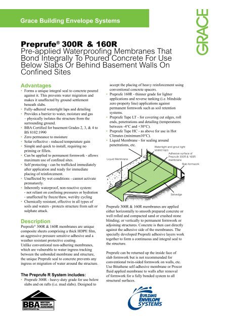
Installation<strong>Pre</strong>prufe ® <strong>300R</strong> & <strong>160R</strong> membranes are supplied in rolls1.2m wide, with a selvedge on one side to provide selfadheredlaps for continuity between rolls. The rolls of<strong>Pre</strong>prufe membrane and <strong>Pre</strong>prufe Tape are interwound witha disposable plastic release liner which must be removedbefore placing reinforcement and concrete.Substrate <strong>Pre</strong>parationAll Surfaces - It is essential tocreate a sound and solid substrateto eliminate movement during theconcrete pour. Substrates must beregular and smooth with no gapsor voids greater than 12 mm. Grout around all penetrationssuch as utility conduits, etc. for stability.Horizontal Blinding - Monolithic concrete blinding ormud slab is preferred. The blinding must be free of looseaggregate and sharp protrusions. An angular profiledblinding is recommended rather than a sloping or roundedsubstrate. The surface does not need to be dry, but standingwater must be removed.Vertical Sheet Piling - Use concrete, plywood, insulationor other approved facing to sheet piling to provide support tothe membrane. Board systems such as timber lagging mustbe close butted to provide support and not more than 12 mmout of alignment.fixings must be covered with a patch of<strong>Pre</strong>prufe Tape. Ensure the underside ofthe succeeding sheet is clean, dry and freefrom contamination before attempting tooverlap. Roll firmly to ensure a watertightseal. Roll Ends and Cut Edges - Overlap all roll ends andcut edges by a minimum 75 mm and ensure the area is cleanand free from contamination, wiping with a damp cloth ifnecessary. Allow to dry and apply <strong>Pre</strong>prufe Tape LT (orHC in hot climates) centered over the lap and roll firmly.Immediately remove printed plastic release liner from thetape.PenetrationsUse the following steps to seal around penetrations such asservice pipes, piles, lightning conductors, etc.Grout around the penetration if the penetration is not stable.Scribe membrane tight to the penetration. If the membrane isnot within 12mm of the penetration, apply <strong>Pre</strong>prufe Tape toCornersInternal and external corners should be formed as shownin the diagrams returning the membrane a minimum of100mm and sealing with <strong>Pre</strong>prufe Tape. Ensure that theapex of the corner is covered and sealed with tape androll firmly. Crease and fold the membrane to ensure aclose fit to the substrate profile and avoid hollows.foldMembrane Installation<strong>Pre</strong>prufe can be <strong>applied</strong> at temperatures of-4ºC or above. During cold or damp conditions, the selvedgeand tape adhesive can be gently warmed using a hot air gunor similar to remove moisture or condensation and improveinitial adhesion.Horizontal Substrates - Placethe membrane HDPE film side tothe substrate with printed coated sideup facing towards the concrete pour.End laps should be staggered to avoida build up of layers. Leave plastic release liner in positionuntil overlap procedure is completed. Accurately positionsucceeding sheets to overlap the previous sheet 75 mm alongthe marked selvedge. Ensure the underside of the succeedingsheet is clean, dry and free from contamination beforeattempting to overlap. Peel back the plastic release liner frombetween the overlaps as the two layers are bonded together.Ensure a continuous bond is achieved without creases androll firmly with a heavy roller. Completely remove the plasticliner to expose the protective coating. Any initial tack willquickly disappear.Internal231fold<strong>Pre</strong>prufe Tape100minExternal23100min<strong>Pre</strong>prufe TapeVertical Substrates - Mechanically fasten themembrane vertically using fixings (i.e. fasteners)appropriate to the substrate with the printedcoated side facing towards the concrete pour. Themembrane may be installed in any convenientlength. Secure the top of the membrane using abatten such as a termination bar or fixing 50 mm below thetop edge. Fixings can be made through the selvedge so thatthe membrane lays flat and allows firmly rolled overlaps.Immediately remove the plastic release liner. Any additional4
cover the gap. Wrap the penetration with <strong>Pre</strong>prufe Tape bypositioning the tape 12 mm above the membrane.Mix and apply Bituthene Liquid Membrane around thepenetrations using a fillet to provide a watertight sealbetween the <strong>Pre</strong>prufe membrane and <strong>Pre</strong>prufe Tape.Membrane RepairInspect the membrane before installation of reinforcementsteel, formwork and final placement of concrete. Themembrane can be easily cleaned by jet washing if required.Repair damage by wiping the area with a damp cloth toensure the area is clean and free from dust, and allow todry. Apply <strong>Pre</strong>prufe Tape centered over the damaged areaand roll firmly. Any areas of damaged adhesive should becovered with <strong>Pre</strong>prufe Tape. Remove printed plastic releaseliner from tape. Where exposed selvedge has lost adhesionor laps have not been sealed, ensure the area is clean anddry and cover with fresh <strong>Pre</strong>prufe Tape, rolling firmly.Alternatively, use a hot air gun or similar to activate adhesiveand firmly roll lap to achieve continuity.Pouring of ConcreteEnsure the plastic release liner is removed from all areasof <strong>Pre</strong>prufe R membrane and Tape. It is recommended thatconcrete be poured within 56 days (42 days in hot climates)of application of the membrane. Concrete must be placedand compacted carefully to avoid damage to the membrane.Never use a sharp object to consolidate the concrete.Alternative wall base detail for early shutter removalWall base detail2 <strong>Pre</strong>prufe Tape 4 Liquid Membrane 6 Hydroduct ®53532 15 1 4150 mm lap1100 mm lapWall base with toe detail showing drainage option300 mmWall base detail against permanent shutter3216475 mm lap21 21line ofpermanent1formwork150 mm lap61100 mm lap100 mm lapPipe penetration2Pile detail4 1reinforcement4 11 <strong>Pre</strong>prufe 3 Bituthene ® or Procor ® 5 ProtectionDetails shown are typical illustrations and not working details. For assistance with detailing and problem solving please contact Grace Technical Department.
Physical PropertiesProperty Typical Value Test Method<strong>300R</strong><strong>160R</strong>ColourWhiteThickness* 1.2 mm 0.8 mm ASTM D3767Peel Adhesion to Concrete 880 N/m ASTM D903 modifiedShear Strength of Joints 440 N/m ASTM D1876 modifiedMethane permeability 9.1 mls/m 2 /day NA University of London, QMW College3Resistance to Hydrostatic Head >70 m ASTM D5385 modifiedLow Temperature Flexibility