Pad ROL⢠200 XT - Johnstech
Pad ROL⢠200 XT - Johnstech
Pad ROL⢠200 XT - Johnstech

You also want an ePaper? Increase the reach of your titles
YUMPU automatically turns print PDFs into web optimized ePapers that Google loves.
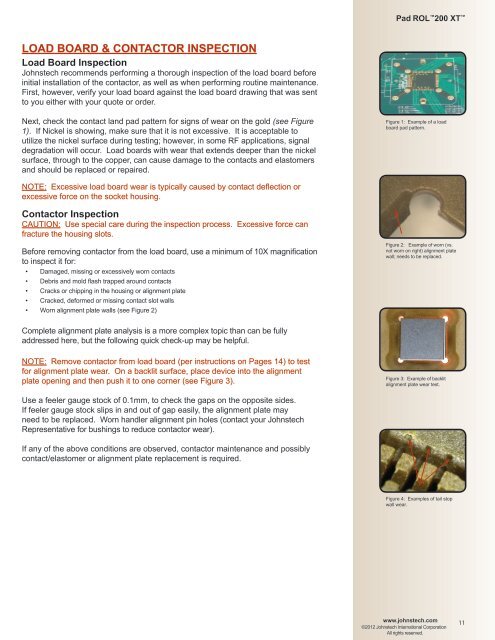
<strong>Pad</strong> ROL <strong>200</strong> <strong>XT</strong> LOAD BOARD & CONTACTOR INSPECTIONLoad Board Inspection<strong>Johnstech</strong> recommends performing a thorough inspection of the load board beforeinitial installation of the contactor, as well as when performing routine maintenance.First, however, verify your load board against the load board drawing that was sentto you either with your quote or order.Next, check the contact land pad pattern for signs of wear on the gold (see Figure1). If Nickel is showing, make sure that it is not excessive. It is acceptable toutilize the nickel surface during testing; however, in some RF applications, signaldegradation will occur. Load boards with wear that extends deeper than the nickelsurface, through to the copper, can cause damage to the contacts and elastomersand should be replaced or repaired.Figure 1: Example of a loadboard pad pattern.NOTE: Excessive load board wear is typically caused by contact deflection orexcessive force on the socket housing.Contactor InspectionCAUTION: Use special care during the inspection process. Excessive force canfracture the housing slots.Before removing contactor from the load board, use a minimum of 10X magnificationto inspect it for:• Damaged, missing or excessively worn contacts• Debris and mold flash trapped around contacts• Cracks or chipping in the housing or alignment plate• Cracked, deformed or missing contact slot walls• Worn alignment plate walls (see Figure 2)Figure 2: Example of worn (vs.not worn on right) alignment platewall; needs to be replaced.Complete alignment plate analysis is a more complex topic than can be fullyaddressed here, but the following quick check-up may be helpful.NOTE: Remove contactor from load board (per instructions on Pages 14) to testfor alignment plate wear. On a backlit surface, place device into the alignmentplate opening and then push it to one corner (see Figure 3).Figure 3: Example of backlitalignment plate wear test.Use a feeler gauge stock of 0.1mm, to check the gaps on the opposite sides.If feeler gauge stock slips in and out of gap easily, the alignment plate mayneed to be replaced. Worn handler alignment pin holes (contact your <strong>Johnstech</strong>Representative for bushings to reduce contactor wear).If any of the above conditions are observed, contactor maintenance and possiblycontact/elastomer or alignment plate replacement is required.Figure 4: Examples of tail stopwall wear.www.johnstech.com©2012 <strong>Johnstech</strong> International CorporationAll rights reserved.11