
You also want an ePaper? Increase the reach of your titles
YUMPU automatically turns print PDFs into web optimized ePapers that Google loves.
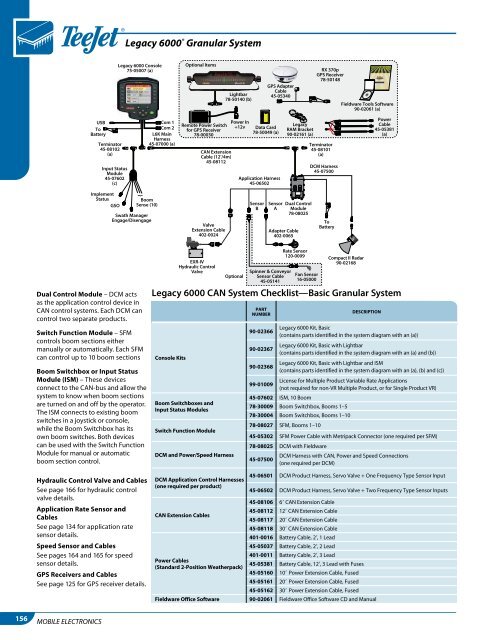
A BLegacy 6000 ® Granular SystemLegacy 6000 Console75-05007 (a)Optional ItemsLightbar78-50140 (b)GPS AdapterCable45-05340RX 370pGPS Receiver78-50148Fieldware Tools Software90-02061 (a)USBToBatteryTerminator45-08102(a)Input StatusModule45-07602(c)Com 1Com 2L6K MainHarness45-07000 (a)Remote Power Switchfor GPS Receiver78-00030CAN ExtensionCable (12’/4m)45-08112Power In+12vData Card78-50049 (a)Application Harness45-06502LegacyRAM Bracket90-02161 (a)Terminator45-08101(a)DCM Harness45-07500PowerCable45-05381(a)ImplementStatusGSO}BoomSense (10)Swath ManagerEngage/DisengageValveExtension Cable402-0024SensorBSensorADual ControlModule78-08025Adapter Cable402-0065ToBatteryDual Control Module – DCM actsas the application control device inCAN control systems. Each DCM cancontrol two separate products.Switch Function Module – SFMcontrols boom sections eithermanually or automatically. Each SFMcan control up to 10 boom sectionsBoom Switchbox or Input StatusModule (ISM) – These devicesconnect to the CAN-bus and allow thesystem to know when boom sectionsare turned on and off by the operator.The ISM connects to existing boomswitches in a joystick or console,while the Boom Switchbox has itsown boom switches. Both devicescan be used with the Switch FunctionModule for manual or automaticboom section control.Hydraulic Control Valve and CablesSee page 166 for hydraulic controlvalve details.Application Rate Sensor andCablesSee page 134 for application ratesensor details.Speed Sensor and CablesSee pages 164 and 165 for speedsensor details.GPS Receivers and CablesSee page 125 for GPS receiver details.EXR-IVHydraulic ControlValveOptionalSpinner & ConveyorSensor Cable45-05141Rate Sensor120-0009Fan Sensor16-05000Compact II Radar90-02168Legacy 6000 CAN System Checklist—Basic Granular SystemConsole KitsBoom Switchboxes andInput Status ModulesSwitch Function ModuleDCM and Power/Speed HarnessDCM Application Control Harnesses(one required per product)partnumber90-0236690-0236790-02368descriptionLegacy 6000 Kit, Basic(contains parts identified in the system diagram with an (a))Legacy 6000 Kit, Basic with Lightbar(contains parts identified in the system diagram with an (a) and (b))Legacy 6000 Kit, Basic with Lightbar and ISM(contains parts identified in the system diagram with an (a), (b) and (c))99-01009License for Multiple Product Variable Rate Applications(not required for non-VR Multiple Product, or for Single Product VR)45-07602 ISM, 10 Boom78-30009 Boom Switchbox, Booms 1–578-30004 Boom Switchbox, Booms 1–1078-08027 SFM, Booms 1–1045-05302 SFM Power Cable with Metripack Connector (one required per SFM)78-08025 DCM with Fieldware45-07500DCM Harness with CAN, Power and Speed Connections(one required per DCM)45-06501 DCM Product Harness, Servo Valve + One Frequency Type Sensor Input45-06502 DCM Product Harness, Servo Valve + Two Frequency Type Sensor Inputs45-08106 68 CAN Extension CableCAN Extension Cables45-08112 128 CAN Extension Cable45-08117 208 CAN Extension Cable45-08118 308 CAN Extension Cable401-0016 Battery Cable, 28, 1 Lead45-05037 Battery Cable, 28, 2 Lead401-0011 Battery Cable, 28, 3 LeadPower Cables(Standard 2-Position Weatherpack)45-05381 Battery Cable, 128, 3 Lead with Fuses45-05160 108 Power Extension Cable, Fused45-05161 208 Power Extension Cable, Fused45-05162 308 Power Extension Cable, FusedFieldware Office Software 90-02061 Fieldware Office Software CD and Manual156MOBILE ELECTRONICS