FEM 9.832
FEM 9.832
FEM 9.832

You also want an ePaper? Increase the reach of your titles
YUMPU automatically turns print PDFs into web optimized ePapers that Google loves.
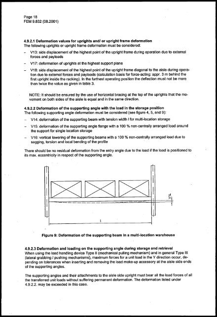
Page 18<strong>FEM</strong> <strong>9.832</strong> (08.2001)4.9.2.1 Deformation values for uprights andl or upright frame deformationThe following uprights or upright frame deformation must be considered:- V13: side displacement of the highest point of the upright frame during operation due to externalforces and payloadsV17: deformation of uprights at the highest support plane- V18: side displacement of the highest point of the upright frame diagonal to the aisle during operationdue to external forces and payloads (calculation basis for force-acting: appr. 3 m behind thefirst upright inside the racking). In the furthest operating position the deflection must not be morethan twice the value as given in table 3.NOTE: It should be ensured by the use of horizontal bracing at the top of the uprights that the movementon both sides of the aisle is equal and in the same direction.4.9.2.2 Deformation of the supporting angle with the load in the storage positionThe following supporting angle deformation must be considered (see figure 4,5, and 9):- V14: deformation of the supporting beam with tension width I for multi-location storage- V15: deformation of the supporting angle flange with a 100 % non-centrally arranged load aroundthe support for single location storage- V16: vertical lowering of the supporting beams with a 100 % non-centrally arranged load due tosagging, torsion and local bending of the profileThere should be no residual deformation from the entry angle due to the load if the load is positioned toits max. eccentricity in respect of the supporting angle.Figure 9: Deformation of the supporting beam in a multi-location warehouse4.9.2.3 Deformation and loading on the supporting angle during storage and retrievalWhen using the load handling device Type 11 (mechanical pulling mechanism) and in general Type III(lateral grabbing I pushing mechanisms), maximum forces for a unit load in the Y direction occur, dependingon tolerances when inserting and removing the load make-up accessory at the aisle side endsof the supporting angles.The supporting angles and their attachments to the aisle side upright must bear all the load forces of allthe transferred unit loads without suffering permanent deformation. The deformation listed under4.9.2.2. may be exceeded in this case.