FEM 9.832
FEM 9.832
FEM 9.832

Create successful ePaper yourself
Turn your PDF publications into a flip-book with our unique Google optimized e-Paper software.
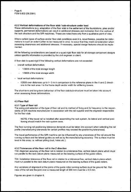
Page 6<strong>FEM</strong> <strong>9.832</strong> (08.2001)4.2.2 Vertical deformations of the floor slab I sub-structure under loadThese deformations (e.g. adaptation of the floor slab to the settlement of the foundations, piles and/orsupports, permanent deformation) can result in additional stresses and inclination from the vertical ofthe rack structure and the SIR machines. These are noted here only from a qualitatve point of view.Where certain types of surface and/or floor slab conditions exist it is, nevertheless, possible for deformationsto such an extent (often to be measured in cms) to occur that they merit consideration whenassessing clearances and additional stresses. If necessary, special design features should be implemented.All the following considerations are based on a quasi-rigid floor slab for all storage component designsunless specific information is provided by the civil engineer or client.A floor slab is quasi-rigid if the following vertical deformations are not exceeded:- overall vertical deformation:1/3000 of the total storage length1/3000 of the total storage width- local vertical deformations:112500 over distances up to I = 3 m in comparison to the reference plane in the X and Z directionsin the rack area. I is the frame depth and/or width for stiffening towers.The short-term and long-term behaviour of the floor slab/sub-structure must be taken into accountwhen assessing these deformations.4.3 Floor Rail4.3.1 Type of floor railThe sizing and selection of the type of floor rail and its method of fixing and its frequency is the responsibilityof SIR machine manufacturer in association with the rail supplier and the engineer responsiblefor the floor slab.NOTE: If the travel rail is installed after assembling the rack system, its lateral and vertical positioningshould match the rack system axes.The floor running rail positioning tolerance demands must be taken into account when selecting the railprofile (manufacturing tolerances for certain profiles may exceed the positioning tolerances).The travel performance of the SIR machine can be influenced by any uneveness of the rail around therunning surface and the lateral guides as well as by the manufacturing accuracy. The surface must belevel in this area, Le. without pitting (rust, holes etc.).4.3.2 Tolerances of the floor rail in the Z directionT19: Alignmen accuracy of the floor rail in relation to a tolerance-free, vertical datum plane which mustrun parallel to the rack datum plane measured on the bearing surface of the guide rollers.T24: Installation tolerance of the floor rail in relation to a tolerance-free, vertical datum plane whichmust run parallel to the rack datum plane measured on the bearing surface of the guide rollers.Any variations of alignment at the joints of the guide roller running surface must be ground flat. Flatnessof the rail and the joint over a measured length of 200 mm must be ::; 0.5 mm.Figures are given in chapter 6.