FEM 9.832
FEM 9.832
FEM 9.832

Create successful ePaper yourself
Turn your PDF publications into a flip-book with our unique Google optimized e-Paper software.
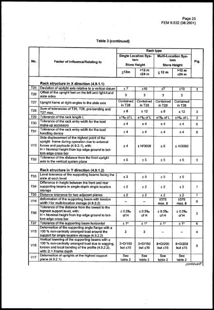
Page 25<strong>FEM</strong> <strong>9.832</strong> (08.2001)Table 3 (continued)No.Factor of Influence/Relatlng toRack typeSingle Location Sys- Multi-Location Systemtem Fig.Store HeightStore Height&12m>12m>12m&12m:!>24ms24mRack structure in X direction (4.9.1.1)T25 Deviation of upright axis relative to a vertical datum ±7 ±10 ±7 ±10 3T26Offset of the upright feet on the left and right-handaisle sides3 3 3 3T27 Upright frame at right-angles to the aisle axisContained Contained Contained ContainedinT~8 inT28 inT28 inT28T28Sum of tolerances of T25, T26, pre-bending andT27 max.±8 ± 12 ±8 ±12 3T29 Tolerance of the rack length L ±1%o of L ±1%0 of L ±1%o of L ±1%o of L 3T30Tolerance of the rack entry width for the loadmake-up accessory±4 ±4 ±4 ±4 6T31Tolerance of the rack entry width for the loadhandling device±4 ±4 ±4 ±4 6Side displacement of the highest point of theupright frame during operation due to externalV13 forces and payloads (4.9.2.1), with: ±4 ± H/3000 ±6 ± H/3000H = Nominal height from top edge ground to bottomedge cross barT32Tolerance of the distance from the front uprightaxis to the vertical system plane±5 ±5 ±5 ±5 3Rack structure in Y direction (4.9.1.2)T33Level tolerance of the supporting beams facing theaisle at each level±3 ±5 ±5 ±5Difference in height between the front and rearT34 supporting beams in single-depth single location ±2 ±2 ±2 ±2 7storageT35 Distance tolerance for two adjacent planes ±2 ±2 ±2 ±2 7V14deformation of the supporting beam with tension 1/375 1/3759T36width I for multi-location storage (4.9.2.2)- -max.8 max.8Tolerance of the distance from the lowest to thehighest support level, with: ± 0.5%0 ±0.5%o ± 0.5%0 ± 0.5%0H = Nominal height from top edge ground to bot- ofH ofH ofH ofHtom edge cross barT37 Tolerance of the supporting beam horizontal ± 1° ± 1° ± 1° ± 1° 6Deformation of the supporting angle flange with aV15 100 % non-centrally arranged load around the 3 3 -- - 4support for single location storage (4.9.2.2)V16V17Vertical lowering of the supporting beams with a100 % non-centrally arranged load due to sagging, 3+0/150 3+0/150 8+D/200 8+D/200torsion and local bending of the profile (4.9.2.2), but s10 but s10 buts15 but s155with: 0 = Frame depthDeformation of uprights at the highest support See See See Seeplane (4.9.2.1) table 2 table 2 table 2 table 2.continued"3