FEM 9.832
FEM 9.832
FEM 9.832

Create successful ePaper yourself
Turn your PDF publications into a flip-book with our unique Google optimized e-Paper software.
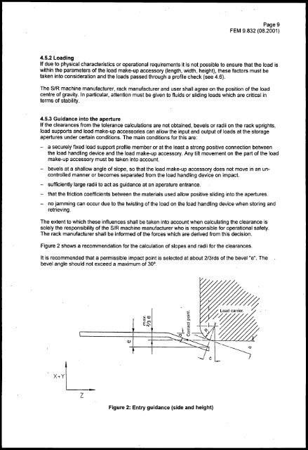
Page 9<strong>FEM</strong> <strong>9.832</strong> (08.2001)4.5.2 LoadingIf due to physical characteristics or operational requirements it is not possible to ensure that the load iswithin the parameters of the load make-up accessory (length, width, height), these factors must betaken into consideration and the loads passed through a profile check (see 4.6).The SIR machine manufacturer, rack manufacturer and user shall agree on the position of the loadcentre of gravity. In particular, attention must be given to fluids or sliding loads which are critical interms of stability.4.5.3 Guidance into the apertureIf the clearances from the tolerance calculations are not obtained, bevels or radii on the rack uprights,load supports and load make-up accessories can allow the input and output of loads at the storageapertures under certain conditions. The main conditions for this are:- a securely fixed load support profile member or at the least a strong positive connection betweenthe load handling device and the load make-up accessory. Any tilt movement on the part of the loadmake-up accessory must be taken into account.- bevels at a shallow angle of slope, so that the load make-up accessory does not move in an uncontrolledmanner or becomes separated from the load handling device on impact.- sufficiently large radii to act as guidance at an aperature entrance.- that the friction coefficients between the materials used allow positive sliding into the apertures.- no jamming can occur due to the twisting of the load on the load handling device when storing andretrieving.The extent to which these influences shall be taken into account when calculating the clearance issolely the responsibility of the SIR machine manufacturer who is responsible for operational safety.The rack manufacturer shall be informed of the forces which are derived from this decision.Figure 2 shows a recommendation for the calculation of slopes and radii for the clearances.It is recommended that a permissible impact point is selected at about 2/3rds of the bevel "e". Thebevel angle should not exceed a maximum of 30°.Q)zFigure 2: Entry gUidance (side and height)