ST-7000-C SERIES - toshiba tec europe
ST-7000-C SERIES - toshiba tec europe
ST-7000-C SERIES - toshiba tec europe
- No tags were found...

Create successful ePaper yourself
Turn your PDF publications into a flip-book with our unique Google optimized e-Paper software.
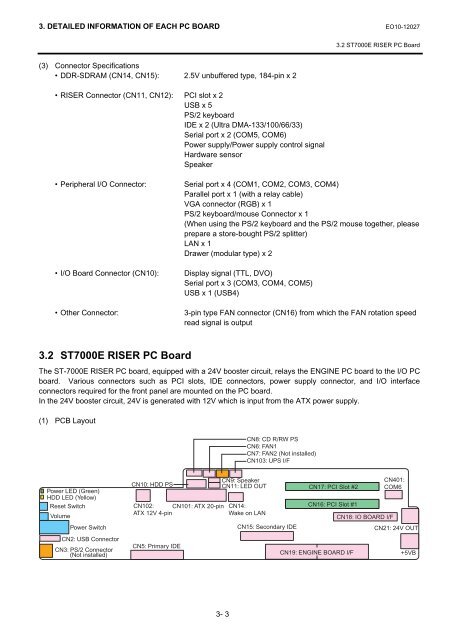
3. DETAILED INFORMATION OF EACH PC BOARD EO10-120273.2 <strong>ST</strong><strong>7000</strong>E RISER PC Board(3) Connector Specifications• DDR-SDRAM (CN14, CN15): 2.5V unbuffered type, 184-pin x 2• RISER Connector (CN11, CN12): PCI slot x 2USB x 5PS/2 keyboardIDE x 2 (Ultra DMA-133/100/66/33)Serial port x 2 (COM5, COM6)Power supply/Power supply control signalHardware sensorSpeaker• Peripheral I/O Connector:• I/O Board Connector (CN10):• Other Connector:Serial port x 4 (COM1, COM2, COM3, COM4)Parallel port x 1 (with a relay cable)VGA connector (RGB) x 1PS/2 keyboard/mouse Connector x 1(When using the PS/2 keyboard and the PS/2 mouse together, pleaseprepare a store-bought PS/2 splitter)LAN x 1Drawer (modular type) x 2Display signal (TTL, DVO)Serial port x 3 (COM3, COM4, COM5)USB x 1 (USB4)3-pin type FAN connector (CN16) from which the FAN rotation speedread signal is output3.2 <strong>ST</strong><strong>7000</strong>E RISER PC BoardThe <strong>ST</strong>-<strong>7000</strong>E RISER PC board, equipped with a 24V booster circuit, relays the ENGINE PC board to the I/O PCboard. Various connectors such as PCI slots, IDE connectors, power supply connector, and I/O interfaceconnectors required for the front panel are mounted on the PC board.In the 24V booster circuit, 24V is generated with 12V which is input from the ATX power supply.(1) PCB LayoutCN8: CD R/RW PSCN6: FAN1CN7: FAN2 (Not installed)CN103: UPS I/FPower LED (Green)HDD LED (Yellow)Reset SwitchVolumePower SwitchCN2: USB ConnectorCN3: PS/2 Connector(Not installed)CN10: HDD PSCN102: CN101: ATX 20-pinATX 12V 4-pinCN5: Primary IDECN9: SpeakerCN11: LED OUTCN14:Wake on LANCN15: Secondary IDECN17: PCI Slot #2CN16: PCI Slot #1CN19: ENGINE BOARD I/FCN401:COM6CN18: IO BOARD I/FCN21: 24V OUT+5VB3- 3