AP 720S Instruction Manual - Hitachi Chemical Diagnostics
AP 720S Instruction Manual - Hitachi Chemical Diagnostics
AP 720S Instruction Manual - Hitachi Chemical Diagnostics
- No tags were found...

Create successful ePaper yourself
Turn your PDF publications into a flip-book with our unique Google optimized e-Paper software.
<strong>AP</strong> <strong>720S</strong> TM<strong>Instruction</strong> <strong>Manual</strong>OPTIGEN®Semi-Automated Instrument
Confidentiality NoticeThe materials and information contained herein are provided by <strong>Hitachi</strong> <strong>Chemical</strong><strong>Diagnostics</strong> Inc. to its customers for their sole use.<strong>Hitachi</strong> <strong>Chemical</strong> <strong>Diagnostics</strong> Inc. retains all rights, title, interest in and copyrights tothe materials and information herein. The materials and information contained hereinconstitute confidential information of <strong>Hitachi</strong> <strong>Chemical</strong> <strong>Diagnostics</strong> Inc. and customershall not disclose or transfer any of these materials or information to any third party.Copyright © 2010<strong>Hitachi</strong> <strong>Chemical</strong> <strong>Diagnostics</strong>, Inc.630 Clyde CourtMountain View, California 94043_________________U.S. and Foreign Patents PendingAll rights reserved. No part of this book may be reproduced in any form withoutwritten permission from <strong>Hitachi</strong> <strong>Chemical</strong> <strong>Diagnostics</strong>, Inc.Document Number: 0780 – ENG Revision: 04Date: April 20101
― Table of Contents ―Page1 User Safety………………………………………………………………….………. 32 System Overview2-1 Specifications…………………………………………………………………. 42-2 Overview………………………………………………………………….…… 52-3 Accessories…………………………………………………………………… 63 Identification of Parts3-1 Front of Instrument………………………………………...…………….…... 73-2 Back of Instrument (Power Panel)………………………………….………. 83-3 Back of Instrument (Aspirate-Drain Panel)…………………………….….. 84 Installation <strong>Instruction</strong>s4-1 General <strong>Instruction</strong>s…………………….……………………….…………... 94-2 Tube Connections………………………………………………..……….….. 105 Preparation Prior to Operation5-1 Power Cord…………………………………………………………..……...... 115-2 Power ON…………………………………………………………….……….. 115-3 Pette Rack…………………………………………………………….…..….. 115-4 Sample/Reagent Rack………………………………………………..……... 145-5 Loading the Racks/Reservoir onto the Instrument…………………..…… 165-6 Preparation of Wash Buffer………………………………………….……… 176 Operation6-1 Procedures for Operation…………………………………………….……... 186-2 Completion of Operation………………………………………………...…... 226-3 Interruption During Operation………………………………………….……. 237 Maintenance7-1 Maintenance Menu…………………………………………………………… 247-2 Cleaning of Instrument………………………………………………..…...… 247-3 Maintenance of Nozzle Head…………………………………….……....…. 257-4 Maintenance of Water Pump MT-11………………………………….…..… 258 Troubleshooting……………………………………………………………………... 262
1 User SafetyWarningRisk of DangerThis symbol is used to indicate that noncompliance with theinstructions or procedures may lead to physical injury, death, or couldcause damage to the instrument.This section includes important information for the safety of the user. Readcarefully before continuing. When using instruments, a number offundamental safety rules must be observed, including the following:• Read all of the instructions prior to use.• Do not immerse the instrument in liquid. See the instructions for maintenance.• Place the instrument on a flat, stable surface that can hold 50kg or more.• Before installation, ensure instrument is at least 20 cm from wall or any objecton the counter/table.• Avoid dust, magnetic fields, excessive humidity and direct sunlight since theymay cause operational errors.• Operate the instrument at room temperature.• Unplug the instrument from the power outlet when not in use or prior tocleaning.• Never operate the instrument with the cable or the plug damaged, if anymalfunctions have occurred or if the instrument has been damaged in any way.• Use maximum care when moving the instrument.• Do not use the instrument for purposes other than those it has been designedfor.• Do not disassemble or modify this instrument in any way.• Do not put foreign objects inside the instrument or open the door during theautomated operation.• Electrical Connection:o This instrument must be properly grounded. In the event of a short circuit,the ground connection reduces the risk of electric shock, allowing theelectrical current to be dispersed.o The plug must be connected to a power outlet that has been correctlyinstalled and grounded. Improper use of ground wire may lead to risk ofelectric shock.o If you are unsure if the power outlet is grounded, contact a qualifiedelectrician.o Do not use multiple extension cords to power the instrument.o Ensure that the power switch is OFF before you insert the power cord.o Do not use a wall socket with multiple outlets.o Handle the power cable with care; avoid pulling and twisting the cable.o The attached power cord is for use in USA/Canada only. For other regions,use an appropriate regional power cord. Failure to do so will result in severedamage to the instrument.o This unit is not equipped with an emergency stop button. For an emergencystop, turn the instrument off using the Power Switch button.3
2 System OverviewThe <strong>AP</strong> <strong>720S</strong> Semi-Automated Instrument is a processor for use with theOPTIGEN platform. The OPTIGEN assay is an in vitro test, which providessemiquantitative measurement of circulating allergen specific IgE antibodies inhuman serum. The OPTIGEN assay is intended to assist in the clinical diagnosisof IgE-mediated allergic disorders.The <strong>AP</strong> <strong>720S</strong> is a processor that automates the manual OPTIGEN assay. Theinstrument aspirates samples and reagents, washes, removes residual fluid fromthe internal channel of the device and washes the nozzle and Pette tips to avoidcontamination.2-1 SpecificationsType…………………………………….<strong>AP</strong> <strong>720S</strong> InstrumentAppearance……………………………. See page 7Case…………………………………….Outer Dimension………………...…….Weight…………………………….…….Body: Firing-painted iron plateBody: 380mm(W)×390mm(D)×505mm(H)Body: Approximately 30kgPower Voltage…………………...…….AC100V~AC240V (50/60Hz)Fuse……………………………………. AC250V 4A TYPE: F (φ 5×20)Consumption Electric Power…..……..Control…………………………….……External Communication…………..…Pollution………………………...……….100W16 bits CPU controlRS-232C (9P-Dsub)Degree II4
2-2 OverviewInstrument ComponentsItemDescription1. Pette Rack Maximum of twenty (20) Pettes can be loaded.2. Sample/ReagentRackSerum Cups (20) + Reagent Reservoirs (2) will be loadedmanually.Two reagent reservoirs are available:Antibody=identified by a blue fill linePhotoreagents=identified by a red fill line3. Nozzle Head Nozzle Head will connect to the top opening of thePettes during the Pette washing, sample and reagentaspiration.4. Sample/ReagentAspirationPettes will move into their specified positions for sampleand reagent aspiration.5. Pette Washing The Pette Tip and the Pette Body will be washed. Wasteliquid will be drained through the vacuum pump.6. Nozzle HeadWashingNozzle Head will be washed with Wash Buffer andDeionized Water. Waste liquid will be drained throughthe vacuum pump.7. LCD Display A touch screen will operate the LCD display.Assay ComponentsNo. OPTIGEN Kit Components Quantity1 Pettes 202 Photoreagent AB 13 Photoreagent CD 14 IgE Antibody 15 Wash Buffer Concentrate 16 White Plugs 227 Black Plugs 22No. Consumables Quantity1 Pette Tips (per bag) 622 Sample Cups (per bag) 10005
2-3 Accessories1 2,3 4 56 7,8 9 1011 12,13No. Instrument Parts Quantity1 Power Cord* 12 Pette Rack 13 Pette Stand 14 Sample/Reagent Rack 15 Antibody Reagent Reservoir (blue) 15 Photoreagent Reservoir (red) 16 Water and Wash Buffer Tubes (Φ 3×Φ 5 silicon 1.5m) 27 Vacuum Tube (orange) (Φ 3×Φ 5 toaron 1.5m) 18 Drain Tube (black) (Φ 3×Φ 5 toaron 1.5m) 19 Water Bottle and Wash Buffer Bottle (1L) 210 Waste Bottle (2L) 111 Over Flow Tray 112 Gasket 113 O-Ring 114 <strong>AP</strong> <strong>720S</strong> <strong>Instruction</strong> <strong>Manual</strong> 115 <strong>AP</strong> <strong>720S</strong> LCD Panel Guide 116 <strong>AP</strong> <strong>720S</strong> Quick Start 1* NOTE: The attached power cord is for use in USA/Canada only. For otherregions, use an appropriate regional power cord. Failure to do so will result insevere damage to the instrument. The Auto-Run time (Priming and Processes)for a maximum of twenty pettes is approximately 4 hours and 45 minutes.6
3 Identification of Parts3-1 Front of InstrumentPower SwitchNozzle HeadLCD DisplayFront DoorHeadWashingStationPette RackSample/ReagentRackNamePower SwitchLCD DisplayFront DoorPette RackNozzle HeadHead WashingStationSample/ReagentRackDescriptionMain power switch ON(I)/OFF(O). The power switch willbe lit green when the power is ON.Operation will be controlled by touch screen.The door must be fully closed when the instrument is inoperation, to activate safety switch.The Pette Rack will be loaded with Pettes and Tips(manual load).Pettes will be positioned for pette wash and aspiration.The Nozzle Head will be washed.Sample Cups and Reagent Reservoir will be loadedmanually.7
3-2 Back of Instrument (Power Panel)NameACFUSERS-232CDescriptionThe power cord attachment willbe inserted hereTwo AC 250V 4A TYPE: F(φ 5×20)Connector for externalcommunication (9P-Dsub)3-3 Back of Instrument (Aspirate-Drain Panel)Air Aspirate(Orange)Drain(Black)Wash Buffer(Yellow)Water(White)NameAIR ASPIRATEDRAINWASH BUFFERWATERDescriptionVacuum tube connection onto the Waste BottleWaste tube connectionWash Buffer tube connectionDeionized Water tube connection8
4 Installation <strong>Instruction</strong>sThe <strong>AP</strong> <strong>720S</strong> should be installed according to the instructions in the Service<strong>Manual</strong>, by a qualified Service Engineer.4-1 General <strong>Instruction</strong>s:• Check that the instrument has not suffered any damage due totransportation.• Place the instrument on a flat, stable surface that can hold 50kg or more.• Before installation, ensure instrument is at least 20 cm from wall or anyobject on the counter/table.• Do not place any object less than 20 cm from the instrument.• Avoid dust, magnetic fields, excessive humidity and direct sunlight sincethey may cause operational errors.• Operate the instrument at room temperature.• Ensure that the power switch is OFF before you insert the power cord.• Do not use multiple extension cords to power the instrument.• Do not use a wall socket with multiple outlets.• The attached power cord is for use in USA/Canada only. For other regions,use an appropriate regional power cord. Failure to do so will result in severedamage to the instrument.• If you must transfer the instrument:o Apply [Drain] function to remove all liquid completely from theinstrument.o Remove the Pette Rack, Sample/Reagent Rack, Over Flow Tray and alltubes from the instrument.o Secure all moving parts such as the Nozzle Head and door.9
4-2 Tube Connections• Connect each tube to a specific color coded tube connector located at theback of the instrument.• Lock the tube connector by turning clockwise, until tightened.• Ensure all tubes are secure and connected to the correct bottle(s). Seefigure below for details.1. Waste Bottle: Black tube into the “DRAIN” connection, Orange tubeinto the “AIR ASPIRATE” connection.2. Wash Buffer Bottle: Yellow tube into the “WASH BUFFER” connection.3. Deionized Water Bottle: White tube into “WATER” connection.1 2 310
5 Preparation Prior to Operation5-1 Power Cord• Ensure the power switch is OFF(O) before inserting the power cord into theoutlet.• Connect the power cord into AC on the back side of the instrument.• The attached power cord is for use in USA/Canada only. For other regions,use an appropriate regional power cord. Failure to do so will result in severedamage to the instrument.5-2 Power ON• Switch the Power ON(I).• The instrument will automatically initialize after about ten seconds frompowering ON.Main Menu screen will appear . Continue with Preparation <strong>Instruction</strong>s .Do not touch the Power Switch with wet hands, as it may cause electricshock.5-3 Pette Rack• Attach one Pette Tip onto each Pette Body.Pette BodyPette Tip• Collect the Pette Rack and Pette Stand. Always use the Pette Stand whenloading or removing the pettes.Pette RackPette Stand11
• Place the Pette Rack onto the Pette Stand. Use the guide bar on the PetteStand to match the guide hole at the bottom of the Pette Rack.Guide Hole atBottom ofPette RackGuide Bar ofPette StandProper fit of the Pette Rack and Stand is shown below:12
• Load the Pettes with attached Pette Tips, one by one, into the cartridges onthe Pette Rack. Always start at position #1 and do not leave anypositions empty when loading.1. The black side of the Pette Body should face the Operator.2. Slide the bottom portion of the Pette Body through the bottom cartridgeopening so that the Pette Body extends past the bottom of the cartridgeplatform.Cartridge OpeningExtension of PetteBody Past CartridgePlatform3. Slide the top of the Pette Body under the upper portion of the cartridge,while pushing down on the Pette Body. Check that the Pette Body iscorrectly positioned and securely attached to the Pette Rack.Pette Body sliding intotop of cartridgeTop of Pette Body inPette Rack cartridgePette Body in positionin Pette Rack13
5-4 Sample/Reagent Rack• Gather the Serum Cups, Antibody Reagent Reservoir (BLUE line), and theSample/Reagent Rack.Sample/ReagentRackSample CupReagent Reservoirfor Antibody• Load the sample cups starting at position #1. Always start at position #1and do not leave any empty positions when loading.• Ensure the quantity of Sample Cups matches the quantity of Pette Bodies.• Use only HCD approved Sample Cups. Other cups may cause theinstrument to malfunction and test results may be lost.• Fill the correct amount of centrifuged serum into the Sample Cups:o 600 µl serum for a 36-allergen petteo 490 µl serum for a 20-allergen petteNOTE: There is a red Sample Fill Line on the Sample/Reagent Rack. Thisline can be used as a guide to check that there is a fill volume ofapproximately 600 µl in the Sample Cups.Sample/ReagentRackSample Fill Line14
• Fill the Antibody Reservoir with the correct amount of Antibody. Refer to thetable below. Gently invert Antibody Reagent Bottle prior to use to mix.PetteNo.Antibody(mL)PetteNo.1 1.6 11 7.62 2.2 12 8.23 2.8 13 8.84 3.4 14 9.45 4.0 15 10.06 4.6 16 10.67 5.2 17 11.28 5.8 18 11.89 6.4 19 12.410 7.0 20 13.0Antibody(mL)BLUE Line15
5-5 Loading the Racks/Reservoir onto the Instrument:• Setting of the Sample/Reagent Rack1. Install the Sample/Reagent Rack first, then insert the Pette Rack into theinstrument.2. Hold the Sample/Reagent Rack so that the position #1 aligns with thered indicator line (see photo below).3. Lower the Sample/Reagent Rack slowly so that the center and thePositioning Pin are aligned into the appropriate hole at the bottom of therack.4. Ensure that the Sample/Reagent Rack is secure and horizontal.5. Ensure the Antibody Reservoir has sufficient Antibody and load onto theSample/Reagent Rack.Sample/ReagentRackPositioning PinCenterSample/ReagentRackRed Indicator Line16
• Setting of the Pette Racko Remove Pette Rack from the Pette Stand.o Hold the Pette Rack so that number #1 cartridge position is front andcenter.o Lower the Pette Rack, insert the center guide bar and the Positioning Pininto the appropriate holes at bottom of the Pette Rack.Pette RackCenter GuideBar of InstrumentPositioning PinPositioning Pino Ensure Positioning Pin is completely set in the hole at bottom of PetteRack.o Close the door.5-6 Preparation of Wash Buffer• Prepare Wash Buffer according tothe instructions in the OPTIGENPackage Insert.• Follow the table below to fill WashBuffer Bottle.PetteQuantityMinimum Volume ofWash Buffer (mL)5 34010 50015 67020 84017
6 Operation6-1 Procedures for Operation: Refer to “<strong>AP</strong> <strong>720S</strong> LCD Panel Guide” fordetails.• When racks are in position, close the door.• Switch the Power ON(I).• The instrument will automatically initialize after about ten seconds frompowering ON.Do not touch Power Switch with wet hands, as it may cause electricshock.NOTE: Do not touch the instrument or any moving parts when theinstrument is in operation.NOTE: This instrument has an inter-lock safety system. If the door opensduring the operation, the system is activated and the instrument can not bestarted/will not run.• Select the type of panel (Panel 20 or Panel 36) from the [Main Menu]screen.18
• Press “Next” and move to the [Check] screen.• Check reagents/water:1. Make sure sufficient Antibody is in the Reagent Reservoir.2. Ensure there is sufficient Wash Buffer in the Wash Buffer Bottle.3. Ensure there is sufficient (1L) Deionized Water in the Deionized WaterBottle and fill if needed.4. Ensure the color of the cap matches with the color coded bottle label.a. Wash Buffer = Yellowb. Deionized Water = White5. Ensure the weighted ends of the Wash Buffer and Deionized Watertubes sit securely at the bottom of their respective bottles.6. Empty the Waste Bottle by pressing the quick release connectors todetach the tubes, unscrew the cap, and then empty the waste liquid.NOTE: The collected waste is a biohazard and should be disposed ofaccording to your local requirements.7. Re-Connect the Waste Bottle. Screw the cap back on and tighten. Attachthe quick release connectors to the cap, and match the color-codedlabels.NOTE: The cap must be tightened completely so that the waste liquidcan drain properly.• Press “Start” to start automated operation.• “Priming” and “Rack & PETs check” will be done automatically, beforestarting “PROCESS”.19
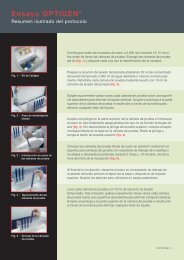
• There are eight (8) processes in all, to complete the Auto-Run.No. Process1 Rehydration2 Sample Aspiration3 Sample Incubation4 Wash5 Antibody Aspiration6 Antibody Incubation7 Wash<strong>Manual</strong>ly Load Photoreagent Mixture8 Photoreagent Aspiration• At the end of Process # 7, <strong>AP</strong> <strong>720S</strong> will pause and an alarm will sound.[Change Photo Rgt] will appear on the screen. Press “Alarm Off”.• Prepare Photoreagent Mixture by thoroughly mixing an equal amount ofPhotoreagent AB and CD. Fill the Photoreagent Reservoir (RED line) withthe correct amount of Photoreagent Mixture.RED LineNOTE: Allow Photoreagent AB and CD to come to room temperature priorto use. Once mixed, the Photoreagent mixture should be used immediatelyfor best results.20
Pette No.PhotoreagentMixture (mL)Photoreagent AB andCD Required (mL)1 1.6 0.8 each2 2.2 1.1 each3 2.8 1.4 each4 3.4 1.7 each5 4.0 2.0 each6 4.6 2.3 each7 5.2 2.6 each8 5.8 2.9 each9 6.4 3.2 each10 7.0 3.5 each11 7.6 3.8 each12 8.2 4.1 each13 8.8 4.4 each14 9.4 4.7 each15 10.0 5.0 each16 10.6 5.3 each17 11.2 5.6 each18 11.8 5.9 each19 12.4 6.2 each20 13.0 6.5 each• Open the door. Remove the Antibody Reservoir and load the PhotoreagentReservoir in the Sample/Reagent Rack. Close the door.• Press “Continue” on [Change Photo Rgt] screen.• Press “Yes” on [Check] screen to start Process #8.• As soon as the first pette is filled with the Photoreagent Mixture, set a timerfor 10 minutes.• At the end of Process #8, an alarm will sound.• Press “Alarm Off” on [Process End] screen.• Open the door. Remove the Pette Rack from the instrument by lifting straightup until it is completely off the Center Guide Bar. Set the Pette Rack in thePette Stand on a table.21
• Insert the black top plug into each pette.• Unload the pettes, one by one, starting from position #1.• Remove the pette tip from each pette body with a gentle twist.• Insert the white bottom plug into each pette.• Load the pettes in order into the Pette Cassette Tray.• At the 10 minutes end of the timer, load the tray in CLA-1 Luminometer toread test results. Refer to the CLA-1 Luminometer Operator <strong>Manual</strong> fordetails (Document No. 0277).6-2 Completion of Operation• Remove the Pette Rack from the instrument. Place the Pette Rack onto thePette Stand.• Remove the Sample/Reagent Rack and close the door.• There are two options:End – to run a second set of Pettes immediately following the first set. Youwill be taken to the [Main Menu], page 18, and can follow the Auto-Runprocedure.Rinse – to clean the instrument at the end of Auto-Run and prepare for shutdown. Continue with the instructions as listed below:Press “Rinse” on [Process End] screen.[Rinse] screen will appear.• Unscrew bottle caps of both Wash Buffer and Deionized Water. Pull out thetube from Wash Buffer and place into the Deionized Water Bottle along withthe Deionized Water tube, which will still be inside the bottle.• Press “Ok”.• After rinse is finished, [Drain] screen will appear.22
• Remove the Wash Buffer and Deionized Water tubes from the DeionizedWater Bottle.• Place Wash Buffer tube and Deionized Water tube on a clean surface duringDrain function. Press “Ok” to start Drain function.• After the Drain function is finished, [Main Menu] will appear. It is now safeto turn power “OFF”.• Rinse Reagent Reservoirs well with Deionized Water.• Clean the instrument as needed. See “Maintenance” for details.6-3 Interruption During Operation• When the Auto-Run is interrupted by pressing the “Pause” key or by openingthe door, a [Run Status] alarm screen will appear (Refer to <strong>AP</strong> <strong>720S</strong> LCDPanel Guide, section 2-8).• Press “Alarm Off” key to stop the alarm. There are two options:Option #1: “Continue” option:If no parts inside the door have been touched or moved, press[Continue] to resume the operation.Option #2: “Cancel” option:If any parts inside the door have been touched or moved, follow thesteps below to ensure that the parts return to the correct alignment atinitialization, before the operation is resumed.a. Press “Cancel” key. [Check] screen will be displayed.b. Press “Yes” key. The panel opening screen will be displayed andfollowed automatically by the initialization screen and the [MainMenu] screen.23
c. Press the “Next” key on the [Main Menu] screen. The “Start/EndProcess and Position Setup” screen will appear (Refer to <strong>AP</strong> <strong>720S</strong>LCD Panel Guide, section 2-9).Confirm the following, as this information is crucial to the run set up:o The Start Process NUMBER is correct on the screeno The End Process NUMBER is correct on the screeno The Pette Position NUMBER is correct on the screenRe-enter the number information as necessary.d. Press “Next” to resume Auto-Run.7 Maintenance7-1 Maintenance MenuThe [Maintenance] menu provides Prime, Rinse, Clock and Language functions.• [Prime] will begin the Priming operation.• [Rinse] will begin the Rinse operation.• [Clock] allows setup of the date and time.• [Language] allows language selection for the screen display.• [Back] will take you to the [Main Menu] screen.7-2 Cleaning of InstrumentDaily maintenance is necessary in order to maintain the performance of theinstrument and to prevent problems during operation.• Wipe the instrument with a soft lint-free cloth. Do not use any solvents asthey may deteriorate the instrument surfaces.• Ensure all surfaces are clean and that no liquids have been spilt.24
7-3 Maintenance of Nozzle HeadReplacement of the O-Ring and Gasket should be done once a year.• Turn the main power “OFF”• Turn the Seal Cap clockwise to remove.NozzleSeal Cap• When the Seal-Cap is removed, you will find the O-Ring and the Gasketinside the Seal Cap.• Remove the O-Ring and Gasket using a pair of tweezers. Be careful if theseal gum is adhered inside of the Gasket.O-RingGasketSeal Cap• To reseal, attach Seal Cap to the nozzle with the replacement O-Ring andGasket inside as shown.• It is important that the replacement O-Ring and Gasket are correctly alignedwithin the Seal Cap.• Wipe the Nozzle Head with a soft, lint-free cloth. Do not use any solvents.7-4 Maintenance of Water Pump MT-11The water pump MT-11 can dry when the instrument is left unused for twomonths or longer. In case of this occurrence contact your distributor formaintenance support.25
8 TroubleshootingIf you experience problems with the instrument, consult the troubleshootingguide below. If repair is needed, contact your Distributor for service.Trouble Cause MeasurePower cord is not connected. Reinsert the power cord.The LCD panelBlown-out fuse(s).Replace with new fuse(s).is not displayedwhen the power The power switch is broken. Repair as needed.is turned ON. A problem has occurred inRepair as needed.the electrical system.The door is open.Securely close the door.Make sure that the rack(s)The rack(s) have not beenhave been set correctly.set properly.Reinstall the rack(s).Warning orAlarm isdisplayed afterthe operationhas beenstarted.The machinedoes not workat START ofoperation. (The“SENSORERROR” isdisplayed.)Liquid(s) cannotbe aspirated.A Pette Tip is missing.Other ProblemsThere is a problem in theelectrical system (damagesensor, motor, or PC board,etc.); or mechanical problem(excessive load on themachinery, broken motor/belt, loosened screws, etc.).Lack of reagent(s).Cracks or breaks in Pette(s).Leakage from Pette Tip(s).Pette(s) are not attachedproperly on Pette Rack.Pette Tip(s) are missing.Gasket and O-Ringdamaged/missingReattach a Pette Tip.Read the Pause/Alarmsection in the LCD PanelGuide.If it is due to the electricalsystem or mechanicalfunction, repair may beneeded.Repair as needed.Check the fill volume table.Replace with new Pette(s).Replace with new PetteTip(s).Reattach the Pette(s) onthe Pette Rack.Attach the Pette Tip(s).Replace with new O-Ringand/or new Gasket.Replenish with WashBuffer for PRIMING again.The pettescannot beLack of Wash Buffer.washed. A problem in the fluidics. Repair as needed.26