Yamaha Digital Audio System Design Guide 8.42MB
Yamaha Digital Audio System Design Guide 8.42MB
Yamaha Digital Audio System Design Guide 8.42MB

You also want an ePaper? Increase the reach of your titles
YUMPU automatically turns print PDFs into web optimized ePapers that Google loves.
The <strong>Yamaha</strong> Advantage<br />
The benefi ts of digital audio networking for professional audio systems are<br />
enormous – a fact that is substantiated by the wide variety of related devices<br />
and formats available from numerous manufacturers. In fact, there are so many<br />
possible approaches and options that the task of designing and implementing the<br />
optimum system for a given application can seem daunting. This publication has<br />
been prepared by <strong>Yamaha</strong> to help you make the right choices for your application,<br />
whichever format or formats you intend to use.<br />
<strong>Yamaha</strong> digital consoles are not only the de-facto industry standard, but they<br />
offer direct compatibility with more third-party protocols that any other consoles<br />
available at the current time. A comprehensive range of <strong>Yamaha</strong> audio interfaces<br />
and networking solutions let you build high-performance pro audio systems of any<br />
scope based on <strong>Yamaha</strong> gear that can be seamlessly integrated with equipment<br />
from other manufacturers as needed. You choose the peripheral devices that<br />
ideally support your application. <strong>Yamaha</strong> provides core processing and control as<br />
well as the interfacing required to bring it all together in the most effi cient, effective<br />
way possible.<br />
For unmatched audio quality, control fl exibility, reliability, scalability, and compatibility,<br />
connect with the best. Connect with <strong>Yamaha</strong>.<br />
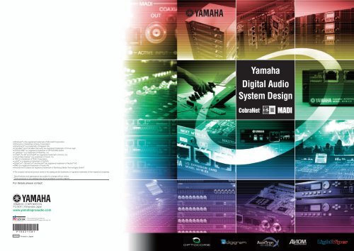
<strong>Yamaha</strong> <strong>Digital</strong> <strong>Audio</strong> <strong>System</strong> <strong>Design</strong><br />
2 Index<br />
3 <strong>Digital</strong> <strong>Audio</strong> Transmission and Networks<br />
6 Key Points of Selecting a Network <strong>Audio</strong> <strong>System</strong><br />
8 EtherSound<br />
8 Products<br />
12 AVS-ESMonitor<br />
16 Mid-size Live SR<br />
17 Large Live SR<br />
18 Stadium<br />
19 Application Example<br />
21 CobraNet<br />
22 Products<br />
23 Mid-size Live SR<br />
24 Banquet<br />
25 Application Example<br />
26 MADI<br />
26 Products<br />
27 Studio<br />
28 Large Live SR<br />
29 Theater<br />
30 Application Example<br />
31 Quality Control<br />
33 Product Line Up<br />
33 <strong>Digital</strong> Mixer<br />
35 Stage Box<br />
37 Plug-in Effects<br />
40 MY Cards<br />
42 Signal Processor<br />
45 Power Amplifi er<br />
47 Appendix<br />
48 AVIOM<br />
53 LightViper<br />
58 OPTOCORE
<strong>Digital</strong> <strong>Audio</strong> Transmission and<br />
Differences between Analog <strong>Audio</strong> and<br />
<strong>Audio</strong> Networks<br />
Whenever transferring multiple channels of audio in analog format,<br />
the devices used for transmission and reception are connected using<br />
thick analog multicore cables. As a cable is required for each channel<br />
being used, the multicore cables comprising all of the necessary<br />
wires can become extremely heavy; in addition, they require<br />
considerable physical effort to handle, and a signifi cant amount of<br />
time and money is needed for their setup and installation.<br />
<strong>Digital</strong>-audio transmission technologies as typifi ed by the AES/<br />
EBU standard convert analog audio into digital signals and have<br />
the advantage of being able to transfer these digital signals with<br />
extremely low levels of audio deterioration. That said, however, they<br />
cannot be said to offer signifi cant advantage in terms of transmittable<br />
channel numbers, bi-directionality, and the like.<br />
Network audio, on the other hand, is an audio transmission format<br />
that makes use of PC network technologies such as Ethernet.<br />
Network audio systems are capable of long-distance, multi-channel,<br />
bidirectional transmission, and they also allow complicated routing<br />
patterns to be confi gured within networks. As a result of the rapid<br />
pace of advancement in digital communication technologies in recent<br />
years, the principal network audio formats in use today can handle<br />
several dozen channels on network-audio cables of, for example,<br />
the Cat5 design, while formats supporting optical- fi ber cables have<br />
an even greater capacity and are capable of transmitting several<br />
hundred channels.<br />
As Cat5, optical-fi ber, and other digital cables can transfer a number<br />
of audio channels that far exceeds that of a single analog multicable,<br />
they offer a major advantage in terms of installation cost and setup<br />
time. Transmission distance also can be extended much further<br />
than before with practically no deterioration in signal quality, and<br />
therefore, digital audio networks offer an overwhelming performance<br />
advantage over analog lines in PA, sound reinforcement, relay<br />
broadcasting, and many other applications. In digital audio networks,<br />
furthermore, input and output channels can be freely setup on<br />
an individual device basis, allowing highly-fl exible systems to be<br />
realized. And since control signals can also be transmitted together<br />
with audio signals, these networks facilitate the setup of advanced,<br />
16-channel analog multicable<br />
Up to 16 channels of audio<br />
Transmission distance: Up to 120 m<br />
Cat5 cable<br />
64-in / 64-out audio channels<br />
Control signals<br />
Transmission distance: 100 m<br />
highly convenient operating environments where, for example, head<br />
amps located a signifi cant distance away from the mixer can be<br />
remotely controlled and the operating status of amp groups can be<br />
monitored.<br />
In order to benefi t from these formidable advantages, applications<br />
that have until now made use of conventional analog lines — for<br />
example, sound reinforcement in live music venues, stadiums, and<br />
theatres; and live broadcasting — are currently undergoing a rapid<br />
change to digital audio networks. Analog lines have traditionally<br />
been seen as the cheaper solution, but digital audio networks are<br />
making inroads here also, and systems such as CobraNet, for<br />
example, also offer cable and switch redundancy as standard. If a<br />
problem were to occur with any of the network's switches or cables,<br />
other cables would be automatically patched in to preserve network<br />
integrity and maintain signal fl ow; consequently, the fl ow of audio<br />
would be completely unaffected and processing could continue as<br />
normal. A range of other network formats making use of advanced,<br />
proprietary technologies in order to further enhance reliability are<br />
also available, and all satisfy the stringent dependability and stability<br />
requirements of the professional environment. Thanks to these<br />
signifi cant advantages, network audio is already providing solutions<br />
in a large number of situations where high-level performance is a<br />
must. And in addition to large-scale installations in many different<br />
countries and world-tour scale concerts here at home, this<br />
technology is also being applied in sound reinforcement, musical<br />
performances, broadcasting, and countless other projects of widely<br />
varying scales.<br />
Advantage of Network <strong>Audio</strong> Signals<br />
Network audio solutions currently suitable for professional<br />
applications all utilize Cat5 or similar cables in order to facilitate<br />
multi-channel transmission of several dozen channels. If also<br />
using optical-fi ber cables, furthermore, dramatic increases can be<br />
achieved in terms of channel numbers and transmission distance.<br />
With analog lines, the longer the transmission distance, the greater<br />
the level of interference due to external noise, making signal<br />
deterioration unavoidable. With network audio, on the other hand,<br />
sound signals are converted into digital format, which in theory,<br />
suffers from absolutely no interference due to external noise. In other<br />
Optical-fiber cable<br />
Ex: Duplex SC type<br />
Several hundred audio channels<br />
Video signals<br />
Control signals<br />
Transmission distance: 2 km over (single mode)<br />
Networks<br />
words, this technology facilitates high-quality transmission of multichannel<br />
audio, regardless of the transmission distance.<br />
<strong>Digital</strong> <strong>Audio</strong> Networks and Cost<br />
Performance<br />
Requiring an individual circuit for each audio channel, standard<br />
analog multicables are extremely heavy and expensive. For example,<br />
a cable of this type with capacity for sixteen channels would weigh<br />
approximately 53 kg per 100 meters, whereas in contrast, the weight<br />
of a Cat5 cable per 100 meters is a mere 6 kg or thereabouts.<br />
Meanwhile, a two-core optical-fi ber cable is also much lighter, at<br />
only about 11 kg for the same length. A professional setup using,<br />
for example, 128 input channels and 32 output channels would<br />
typically require a total of ten analog multicables, each handling<br />
16 channels; however, if a network audio solution were used, the<br />
same performance level could be achieved with two Cat5 cables<br />
or a single optical-fi ber cable. And since this difference in weight<br />
and cost becomes more and more pronounced as the transmission<br />
distance grows, the advantage offered by network audio solutions<br />
over analog audio is beyond doubt.<br />
In analog audio installations, furthermore, cables must often be<br />
laid and connected in complicated patterns in order to match<br />
system diagrams; however, as the fl ow of audio signals can be<br />
easily controlled using software with many network-audio formats,<br />
the same systems can be realized with but a handful of physical<br />
connections. In this type of case, therefore, not only is it possible<br />
to achieve remarkable savings in terms of time and effort, but the<br />
potential for mistakes or problems associated with large amounts of<br />
manual labor can also be sharply reduced. Even after installation,<br />
furthermore, these network audio solutions allow signal routing,<br />
channel numbers, and other system parameters to be modifi ed<br />
and adjusted in a highly fl exible way using the same software, thus<br />
generating massive improvements in the effi ciency and ease of work<br />
associated with system installation and setup.<br />
Left: Optical-Fiber cable, Right: Analog Multi cable<br />
Control Functions<br />
A large number of digital audio networks also facilitate the transmission<br />
of control signals together with multi-channel audio, and as such,<br />
make it possible to create highly-advanced, highly-controllable audio<br />
environments. For example, this type of setup allows networked<br />
devices such as power amplifi ers and remote head amps integrated<br />
into A/D converters to be conveniently monitored and controlled. In<br />
addition, central control and monitoring of groups of devices located<br />
some distance away in amplifi er rooms or equipment rooms can also<br />
be carried out via a PC or digital mixer.<br />
Selecting the Best Network <strong>System</strong><br />
A host of network audio systems with differing formats are currently<br />
available from a wide range of manufacturers. Regardless of<br />
whether a network is to be used with PA and sound-reinforcement<br />
equipment for live performances and concerts or for broadcasting,<br />
the ideal format is normally selected based on a number of different<br />
factors — for example, the size and purpose of the installation site,<br />
the number of channels needed, transmission distances, whether<br />
or not redundancy is required in order to further enhance reliability,<br />
device compatibility requirements, and the level of latency (i.e.,<br />
delay) occurring as a result of audio processing or inherent to the<br />
network system itself.<br />
Once a network format has been chosen in line with the specifi c<br />
advantages that it offers, it is generally possible to combine devices<br />
from multiple manufacturers in order to confi gure the actual network,<br />
as long as they all support the same format. With <strong>Yamaha</strong> professional<br />
audio equipment, however, it is also possible to directly connect<br />
devices compatible with different network-audio formats. More<br />
specifi cally, <strong>Yamaha</strong> products can be fi tted with two or more mini-<br />
YGDAI cards for different network formats in order to also function<br />
as a format converter, thus vastly expanding the range of potential<br />
applications. Thanks to the open architecture concept adopted in the<br />
design and development of these products, our professional audio<br />
equipment can be combined with all types of network-audio format,<br />
and regardless of scale, can also be positioned right at the heart<br />
of these networks. In fact, <strong>Yamaha</strong>'s digital mixers have become<br />
the de-facto standard for this type of central role, which itself is<br />
testament to the ability of these products to support many different<br />
system solutions in order to meet the varying needs of the market.<br />
In addition to superior levels of quality and reliability, therefore,<br />
this represents a further advantage of <strong>Yamaha</strong> professional audio<br />
equipment.<br />
3 <strong>Yamaha</strong> <strong>Digital</strong> <strong>Audio</strong> <strong>System</strong> <strong>Design</strong><br />
<strong>Yamaha</strong> <strong>Digital</strong> <strong>Audio</strong> <strong>System</strong> <strong>Design</strong> 4
Key Technology<br />
Mini-YGDAI Cards and Card Slots<br />
I/O slots are provided on <strong>Yamaha</strong> digital mixers, processors, power amps, and the like in order to facilitate the fi tting of expansion cards. More<br />
specifi cally, these cards are correctly known as mini-YGDAI cards (where YGDAI stands for <strong>Yamaha</strong> General <strong>Digital</strong> <strong>Audio</strong> Interface), and as<br />
the name suggests, they represent a proprietary standard for audio I/O expansion.<br />
A large number of compatible interface cards can be inserted into mini-YGDAI card slots in order to add support for many different audio signal<br />
formats. <strong>Yamaha</strong>’s lineup of mini-YGDAI (or MY) cards comprises as many as 20 different types (as of Oct. 2008), and third-party interface<br />
cards from various other manufacturers provide additional support for various formats and applications. Practically every <strong>Yamaha</strong> digital mixer<br />
available today features one or more mini-YGDAI slots, meaning that you can freely choose the best MY cards for your specifi c requirements.<br />
The principal advantages of mixers and processors featuring MY slots are as follows:<br />
• The number of I/O channels can be expanded beyond the device’s original physical limit.<br />
• Cards can be installed to instantly realize support for analog, AES/EBU, TDIF, A-DAT, EtherSound, and CobraNet I/O formats (see below), while<br />
networking and DSP effect functionality is also provided by third-party products. In addition, cards can be easily interchanged to support many<br />
different formats.<br />
• <strong>Audio</strong> signals input into the device can be converted to the card’s specifi c format for output.<br />
On the <strong>Yamaha</strong> Professional <strong>Audio</strong> site, you can visit the I/O Card Matching page in<br />
order to determine the number of MY cards that can be used with each model, conditions<br />
applying to their usage, and other important information. For more information, please use<br />
the following URL:<br />
http://www.yamahaproaudio.com/<br />
*Information on network cards is available from the product page for the protocol in question.<br />
*Please turn to page 37 for information on other MY cards.<br />
HA Remote<br />
HA Remote is a <strong>Yamaha</strong> technology that uses RS422 signals to remotely control head amplifi ers. With this functionality, it is possible to control<br />
the head amps on <strong>Yamaha</strong> AD8HR A/D converters from a <strong>Yamaha</strong> digital mixer — for example, the FOH mixer could be used to remotely control<br />
one or more AD8HRs located at the side of the stage. In fact, when a <strong>Yamaha</strong> digital mixer is combined with an AD8HR operating as a stage<br />
box, this extremely convenient function allows gain to be controlled remotely in steps of 1 dB. The majority of the digital consoles* in the <strong>Yamaha</strong><br />
product lineup feature HA Remote connectors in order to provide support for remote head-amp control. Once connected to a <strong>Yamaha</strong> mixer<br />
via HA Remote, the AD8HR’s head-amp gain levels and HPF frequencies can be remotely controlled, and in addition, it is also possible to turn<br />
phantom power and the HPFs on and off from the mixer.<br />
*A remote connector can be added to the LS9 by installing an MY16-ES64 card or the like.<br />
Use a D-sub 9-pin<br />
cross cable for HA<br />
Remote control.<br />
EtherSound, CobraNet, and other major network audio formats provide the capacity for head-amp remote signals and the like to be transmitted<br />
and received together with audio data. A single Cat5 or optical-fi ber cable can easily carry these signals, allowing for highly convenient remote<br />
control over long distances without the cost and effort associated with extra cabling.<br />
Key Points for Selecting a Network <strong>Audio</strong> <strong>System</strong><br />
As described above, a host of different network audio formats and standards are currently available, and sound professionals<br />
in fi elds such as sound reinforcement, facility acoustics, production studios, and broadcasting have wholeheartedly adopted<br />
these network audio solutions. This technology is no longer simply being tested or experimented with; rather, network audio has<br />
become a convenient and reliable means of confi guring audio systems for today's diverse requirement and environments.<br />
When it comes to practical deployment of network audio, two critical points must be considered — namely, selecting a suitable<br />
format for your application and designing a system that allows the merits of the selected format to be maximized. Each format<br />
has its own distinctive advantages and disadvantages, and therefore, it is important to study them carefully before making a<br />
selection.<br />
<strong>Yamaha</strong> Supports an Open Architecture <strong>Design</strong> for Network <strong>Audio</strong><br />
Generally speaking, different network audio formats are mutually incompatible, and once your system has been deployed, changing the format<br />
used can be a major undertaking. Requiring not only the replacement of network devices, this may also call for reinstallation, or even worse,<br />
complete rebuilding of your facility. It goes without saying, therefore, that format selection before deployment is the most critical factor.<br />
To reduce the level of associated risk, <strong>Yamaha</strong> pro audio devices can be fi tted with MY cards in order to support practically all I/O formats.<br />
Thanks to this open architecture design, systems can be designed with a higher degree of fl exibility. Individual <strong>Yamaha</strong> pro audio devices<br />
can handle as many different formats as they have MY card slots; accordingly, devices with two or more such slots can be used to interface<br />
between audio networks of different formats. Already operating as format converters in many different environments, <strong>Yamaha</strong> pro audio<br />
devices add more fl exibility to the design and planning of network audio systems.<br />
KEY POINT 1: Required Number of Channels and Network Topology<br />
As in the design of an analog mixing system, fi rst examine the total number of I/O channels needed, the physical arrangement of<br />
I/O devices, and physical signal routings. Based on what you fi nd, consider how the various network audio formats would suit your<br />
needs. Formats vary in terms of the number of I/O channels supported, possible routing patterns, and network topology (that is,<br />
how devices can be connected within the network); furthermore, topologies also differ from each other in terms of connectivity,<br />
expandability, and their level of protection against network failure. That said, however, certain formats can support two or more<br />
different topologies. Since the physical arrangement of devices depends greatly on the topology selected, it is important to also<br />
consider the relative importance of connectivity, expandability, and reliability in terms of your network audio system.<br />
Typical Topologies<br />
Point-to-Point Star (CobraNet, etc.)<br />
Two devices are connected via a<br />
single cable.<br />
Advantages:<br />
The standard for today's PC networks, star<br />
configurations support distributed installation<br />
and are highly flexible when it comes to the<br />
addition and removal of individual devices.<br />
Disadvantages:<br />
Failure of the Ethernet switch at the<br />
center of the network affects all devices.<br />
Ring (Optocore, EtherSound, etc.) Daisy Chain (EtherSound, AVIOM, etc.)<br />
Advantages:<br />
As signals flow both clockwise and<br />
counterclockwise around the ring,<br />
failure of a specific device will not<br />
affect the entire network.<br />
Disadvantages:<br />
Network reconfiguration (i.e.,<br />
addition or removal of devices) may<br />
be difficult and require re-wiring.<br />
KEY POINT 2: Latency and Sound Quality<br />
Advantages:<br />
With simple, series-type connections<br />
between devices, networks are easy to<br />
configure.<br />
Disadvantages:<br />
Failure of any device other than those at<br />
the ends of the daisy chain splits the<br />
network in two.<br />
Network audio formats also vary in terms of system latency and sound quality. Latency determines the amount of delay in signal<br />
transfer, while sound quality is determind by sampling rate, bit depth, and other similar parameters. As such, both are important<br />
factors to consider when selecting a network audio format. It is important to determine your system's absolute requirements with<br />
regard to each.<br />
5 <strong>Yamaha</strong> <strong>Digital</strong> <strong>Audio</strong> <strong>System</strong> <strong>Design</strong><br />
<strong>Yamaha</strong> <strong>Digital</strong> <strong>Audio</strong> <strong>System</strong> <strong>Design</strong> 6
7<br />
KEY POINT 3: Network <strong>Audio</strong> Protocols<br />
Network audio formats are categorized according to whether they are based on standard Ethernet protocols or other proprietary<br />
protocols. In this section, we consider the pros and cons of both.<br />
<strong>Yamaha</strong> <strong>Digital</strong> <strong>Audio</strong> <strong>System</strong> <strong>Design</strong><br />
Network audio protocols<br />
Ethernet-based CobraNet, EtherSound, etc.<br />
Proprietary AVIOM, Optocore, LightViper, etc.<br />
● Ethernet-based protocols<br />
Ethernet-based networks are confi gured using standard Ethernet devices such as switches and media converters, and therefore,<br />
a wide range of options are available, even on a tight budget. Using advanced Ethernet functions such as VLAN (virtual LAN) and<br />
STP (spanning tree protocol), furthermore, signals other than audio can also be transferred over these networks. The establishment<br />
of redundancy in networks as protection against localized failure is also fully supported, although this may require a higher level of<br />
networking expertise in device selection and system confi guration.<br />
● Proprietary protocols<br />
<strong>Audio</strong> networks confi gured using proprietary protocols employ dedicated devices and procedures, and as such, can deliver time<br />
savings when it comes to device selection and system confi guration. With user convenience in mind, proprietary products are often<br />
developed for specifi c applications, which gives rise to both advantages and disadvantages. Even if such solutions are initially<br />
perfect for your system, they may later prove infl exible or present compatibility problems upon expansion, however small. Generally<br />
speaking, systems confi gured using dedicated devices are relatively costly.<br />
KEY POINT 4: Compatibility Information<br />
Once format and basic topology have been settled, the network peripherals required to confi gure the basis of your audio network<br />
must be determined. Depending on your system requirements, such devices can include Ethernet switches for extending or<br />
branching Cat5e cables and media converters for interchanging Cat5e and optical-fi ber cables. Popular network peripherals, which<br />
may realize a higher level of compatibility, may be available from your system vendor. In the majority of cases, however, devices<br />
from various different manufacturers are used to confi gure network audio systems. Accordingly, it is important to confi rm that the<br />
devices you intend to use are free of compatibility issues. Today, many manufacturers and vendors publish such information on their<br />
websites. It is a good idea to regularly check this product, support, and compatibility information before fi nalizing your design.<br />
KEY POINT 5: <strong>System</strong> Management<br />
You may be wondering how — in addition to audio signals transferred via network cables – the status of each device deployed<br />
within an audio network can be monitored and managed. The solution is generally simple, and while network audio devices normally<br />
support remote control, it does depend on the specifi c devices and network format used. Certain devices can be controlled from<br />
a networked computer running a dedicated software tool, while others may require control signals from hardware connected via a<br />
special control line; naturally, it is important to be aware of these differences. As many of the popular network audio formats support<br />
the transfer of control signals together with audio, most devices can be controlled directly over the network; however, certain other<br />
devices may require a separate control line in order to be controlled. Be sure to check the specifi cations of the devices to be used<br />
in order to confi rm whether or not additional control lines will be needed.<br />
Tip regarding computers for system management<br />
First and foremost, a computer used for system management must be highly stable in continuous use, and in order to avoid any<br />
potential diffi culties, it is critical that unnecessary system load be eliminated. Turn off the screen-saver, auto-sleep, and other<br />
energy-saving features or programs running in the background. In doing so, you will make your computer more responsive<br />
overall.<br />
EtherSound<br />
EtherSound Technology Overview<br />
EtherSound<br />
EtherSound is a protocol for network audio developed by Digigram of France. Using this technology, it is possible to both<br />
transmit and receive up to 64 channels of 24-bit / 48-kHz audio data using a single Cat5 cable. Alternatively, 32 channels of<br />
uncompressed, 24-bit / 96-kHz audio data can be transferred in each direction. And in addition to audio, HA Remote and other<br />
control signals can also be exchanged using this protocol. Compliant with the IEEE802.3 (100Base-TX) standard, EtherSound<br />
can be used with general-purpose Cat5 cables, media converters, and switches. And as with networks within companies,<br />
EtherSound supports the confi guration of VLANs. Network connections can be daisy-chained, setup in a star pattern using a<br />
switch, or arranged as a combination of the two.<br />
If using Cat5 cables, the distance between devices can be approximately 100 m*; however, this can be further extended by<br />
converting signals into optical data using a media converter. What’s more, ring networks can also be setup in order to realize<br />
redundancy for higher levels of stability. In such a confi guration, the fi rst and last devices in a daisy-chained series are also<br />
connected in the same way to form an inter-connected ring. Even if a problem were to develop at any specifi c connection point,<br />
the system would be able to continue operating normally. This, among other reasons, explains why EtherSound has become the<br />
focus of considerable industry attention.<br />
When operating at a sample rate of 48 kHz, network latency is only 5 samples or 104 µs, and this increases by a mere 1.4 µs<br />
for each additional node (the name given to switches and other network devices). As such, EtherSound is the perfect choice for<br />
systems where minimizing signal delay is paramount. And in order to facilitate the setting and monitoring of EtherSound network<br />
devices from a Windows PC, AuviTran has made its dedicated software package AVS-ESMonitor available as a free download.<br />
For more details, please visit http://www.auvitran.com.<br />
(*Maximum transmission distances depend on cable quality. For more details, please visit http://www.ethersound.com)<br />
EtherSound Topologies<br />
■ Daisy Chain Confi guration<br />
In a daisy chain — the simplest of confi gurations — all network devices are connected in<br />
series. Daisy-chain networks are benefi cial in two ways, allowing extremely simple routing<br />
of data and delivering fast transmission times. With each additional EtherSound device<br />
added to a daisy-chain network, latency increases by only 1.4 µs. On the other hand, if<br />
one connection within the chain were to fail, all downstream devices would be adversely<br />
affected. A cable failure within a daisy chain causes the system to be split in two and<br />
prevents signals from fl owing beyond the point of the failure.<br />
Furthermore, even if the daisy chain were to contain devices that could potentially exhibit<br />
unstable operation, such as a PC running DAW software, an End Loop point could be setup<br />
immediately in front of that device to ensure that it only receives signals. With this type of<br />
countermeasure in place, it is even possible to reboot the PC without adversely affecting the<br />
system as a whole. (For more details, see Setting an End Loop below.)<br />
■ Ring Confi guration<br />
In a daisy chain, in the event of a cable failure,the system was split in two, preventing<br />
signals from fl owing beyond the point of the failure.<br />
To overcome this, both ends of the daisy chain can be connected together, to realize a<br />
redundant system. This type of confi guration is known as a ring topology.<br />
Even if a failure occurs on one part of the network, the network as a whole is not affected.<br />
However when using ring topologies, the number of channels on the entire network is<br />
limited to 64. To use ring topologies, all EtherSound devices must support ring topologies,<br />
and network switches may not be used. Although many producers of EtherSound products<br />
are still developing devices capable of being confi gured in a ring, a number of compliant<br />
devices with the ES-100 logo are currently available (see below).<br />
■ Star Confi guration<br />
To realize a star-shaped confi guration, a switch is placed between two daisy-chained<br />
devices, with additional daisy-chains extending out from this junction point. In addition<br />
to being very easily expanded, this type of confi guration permits new devices to be<br />
conveniently added at any point within an existing network. However it is only possible to<br />
send downstream through a switch.<br />
In the fi gure on the right, the network has a star confi guration immediately downstream<br />
from a switch, and therefore, the switch can only send data to the branches of the star — it<br />
cannot receive from them. Nevertheless, the branches can be seen as individual daisy<br />
chains facilitating two-way communication between each of the component devices.<br />
Devices downstream of an End Loop will receive,<br />
but not transmit data.<br />
Failure of any device or connection<br />
splits the system in two.<br />
End Loop<br />
For the details on confi guration of <strong>Yamaha</strong> EtherSound devices, please refer to ''EtherSound Setup <strong>Guide</strong>'' at the <strong>Yamaha</strong> pro<br />
audio website: http://www.yamahaproaudio.com<br />
Primary<br />
Master<br />
Two-way<br />
communication<br />
is not possible<br />
across switches.<br />
Switch<br />
DAW<br />
<strong>Yamaha</strong> <strong>Digital</strong> <strong>Audio</strong> <strong>System</strong> <strong>Design</strong> 8
9<br />
EtherSound EtherSound<br />
Products<br />
EtherSound Interface Card<br />
MY16-ES64<br />
The MY16-ES64 is a Mini-YGDAI card providing<br />
support for EtherSound In addition to the 16-in /<br />
16-out channels of audio handled by this card,<br />
MY16-EX expansion boards can also be added to<br />
further boost the number of channels. With each<br />
MY16-EX adding a maximum of 16-in / 16-out channels and connection of up to three of these boards supported, the MY16-ES64 can be<br />
expanded to handle up to 64-in / 64-out channels in total. (Four card slots will be required for such a confi guration.)<br />
I/O Expansion Board<br />
MY16-EX<br />
The MY16-EX is an expansion card for use with the<br />
MY16-ES64 or MY16-MD64 interface card. A single<br />
board is capable of 16-in / 16-out communication,<br />
allowing communication with a host to be confi gured as follows:<br />
• Master card and one MY16-EX card: 32-in / 32-out<br />
• Master card and two MY16-EX cards: 48-in / 48-out<br />
• Master card and three MY16-EX cards: 64-in / 64-out<br />
Please note that the MY16-EX cannot be used as a stand-alone unit.<br />
MY16-EX Card Connections<br />
The MY16-EX is an expansion board for use with the MY16-ES64<br />
Ethernet interface card or the MY16-MD64 MADI interface card. Up to<br />
three MY16-EX cards can be combined with an MY16-ES64 or MY16-<br />
MD64 operating as master (for a maximum of four cards overall), and in<br />
such a case, up to 64-in / 64-out channels of digital audio data can be<br />
handled. When connecting cards together, it is important that straighttype<br />
LAN cables (STP*) of Cat5 or better be used and that they be kept<br />
as short as possible (i.e., no more than 3 meters).<br />
Connections from the master card (MY16-ES64 or MY16-MD64) must<br />
be made in the same order as defi ned by the SW1 dipswitches on the<br />
MY16-EX cards. In the setup shown here, the master card (MY16-ES64<br />
or MY16-MD64) is inserted into Slot 1, while Slot 2, Slot 3, and Slot 4 are<br />
occupied by MY16-EX cards with the SW1 dipswitch set to 1, 2, and 3,<br />
respectively. Accordingly, the communication sequence is Slot 1 ➝ Slot<br />
2 ➝ Slot 3 ➝ Slot 4.<br />
*Shielded Twisted Pair (STP) cables The LAN cables generally referred to as Ethernet cables come in two different types — namely, UTP (twisted pair) and STP<br />
(shielded twisted pair). Shielded twisted pair cables protect signals from external noise, thus allowing faster communication speeds. As these cables feature a<br />
built-in shield, furthermore, the devices and systems connected using them must be grounded. We recommend that STP-type, straight LAN cables of Cat5 or better<br />
be used with the MY16-EX.<br />
Network <strong>Audio</strong> Interface<br />
NAI48-ES<br />
Offering up to 48 I/O channels, the NAI48-ES can be used to interface between EtherSound and AES/EBU. This advanced device can also<br />
exchange word clock signals and supports connection of a redundant power supply for failsafe operation. What’s more, HA Remote control<br />
signals can be exchanged together with digital audio data via Cat5 cables. This functionality and performance makes the NAI48-ES the perfect<br />
choice for stage boxes.<br />
1 2 3 4 5 6<br />
<strong>Yamaha</strong> <strong>Digital</strong> <strong>Audio</strong> <strong>System</strong> <strong>Design</strong><br />
Example: Rear panel of PM5D-RH<br />
<strong>Digital</strong> Mixing Console<br />
Slot 4: MY16-EX (Slave 3)<br />
Slot 2: MY16-EX (Slave 1)<br />
Slot 3: MY16-EX (Slave 2)<br />
Slot 1: MY16-ES64 (Master)<br />
Rear Panel<br />
Products<br />
NAI48-ES Rear Panel<br />
1 EXT DC INPUT connector<br />
XLR-4-32 type connector allowing for the supply of external power (at<br />
+12 V) to the NAI48-ES as a backup for its internal power supply.<br />
2 HA Remote connector<br />
3 Word clock terminals<br />
HA Remote Settings for NAI48-ES and <strong>Digital</strong> Mixer<br />
In order that HA Remote signals can be relayed to AD8HRs (AD converters supporting remote head-amp control) connected to an<br />
NAI48-ES, settings must be made for the mixer’s ES card and the NAI48-ES. A PC running the application AVS-ESMonitor is used to<br />
make these settings. Available as a free download from AuviTran, AVS-ESMonitor can be used to confi gure audio routing and to setup<br />
remote control for devices on EtherSound networks. In terms of <strong>Yamaha</strong> products, this application provides individualized support for<br />
the MY16-ES64, the NAI48-ES, DME Satellite ES series, and the SB168-ES.<br />
Using AVS-ESMonitor, a mode setting for the NAI48-ES is made based on the model of the mixer that will communicate with this<br />
interface unit via the MY16-ES64 expansion card. For more details on establishing routes for HA Remote signals in this way, please<br />
refer to the section on AVS-ESMonitor below.<br />
Mode settings for the different mixer models are as follows.<br />
● LS9 <strong>Digital</strong> Mixing Console: Set to Mode 2<br />
● PM5D or M7CL <strong>Digital</strong> Mixing Console; DM2000 or DM1000 <strong>Digital</strong> Production Console: Set to Mode 3<br />
With the correct mode setup, remote-control signals will be transmitted via the Cat5 cable, allowing you to make full use of HA Remote<br />
functionality.<br />
DME Satellite ES Series for EtherSound<br />
Fitted with high-quality mic preamps supporting HA Remote, <strong>Yamaha</strong>’s DME Satellite ES series make it possible to add analog inputs, outputs,<br />
or both to low-latency EtherSound networks. Specifi cally, the DME8i-ES adds 8 analog inputs to an EtherSound network; the DME8o-ES, 8<br />
analog outputs; and the DME4io-ES, 4 analog inputs and 4 analog outputs. The ES series can also send and receive 16 channels of digital<br />
audio on EtherSound networks and provides a host of advanced signal-processing functions. For example, this functionality could easily be<br />
applied to operate a DME8o-ES as a speaker processor, controllable via the network.<br />
Control of these signal processors is achieved using the PC application DME <strong>Design</strong>er, allowing a wealth of audio-processing components<br />
such as EQ, crossover, and delay to be freely and intuitively confi gured. Furthermore, with Remote (RS-232C/RS-422), GPI, and Ethernet<br />
connectors also included as standard, many other types of control are also supported.<br />
DME8i-ES 8 analog inputs<br />
DME Satellite adding 8 analog input channels to EtherSound networks.<br />
DME8o-ES 8 analog outputs<br />
DME Satellite adding 8 analog output channels to EtherSound networks.<br />
DME4io-ES 4 analog inputs and 4 analog outputs<br />
DME Satellite adding 4 analog input and 4 analog output channels to EtherSound networks.<br />
DME8i-ES Rear Panel<br />
1 Network connector<br />
100Base-TX/10Base-T Ethernet connector for connecting to a computer<br />
or another DME unit.<br />
2 Remote connector<br />
D-sub 9-pin connector for connecting to devices supporting HA Remote<br />
and external RS232C/422 compatible controllers.<br />
4 AES/EBU connectors<br />
Used for the input and output of digital audio signals. Each is capable of<br />
handling 8 I/O channels. Note that only connectors 1 through 4 are active<br />
when the unit is operating in Double Speed mode (i.e., 88.2 / 96 kHz).<br />
5 EtherSound input and output connectors<br />
6 I/O send (TX) and receive (RX) indicators<br />
DME8i-ES/DME8o-ES/DME4io-ES Front Panel<br />
1 2 3 4<br />
DME8i-ES Rear Panel<br />
3 GPI connector<br />
Euroblock connector for input and output of control signals. Provides 8<br />
channels of input and 4 channels of output.<br />
4 Analog input connectors<br />
Euroblock-type input connectors.<br />
<strong>Yamaha</strong> <strong>Digital</strong> <strong>Audio</strong> <strong>System</strong> <strong>Design</strong> 10
11<br />
EtherSound EtherSound<br />
Products<br />
AuviTran<br />
Based in France, AuviTran was established around a core of staff members from Digigram’s EtherSound product development<br />
department. Applying specialist expertise and know-how, the company is focused on the development of solutions using<br />
EtherSound technologies.<br />
AVRed-ES Series of EtherSound Redundant-Link Management Units<br />
The AVRed-ES series provides a range of EtherSound redundant-link management units in a compact 1U rack size. These units ensure highly<br />
stable EtherSound connections using two redundant links. Offering a choice of Cat5 cable connectors or optical-fi ber cable connectors for<br />
input and output, the series adds support for a range of different systems.<br />
AVRed-ES<br />
Support for EtherCon connectors<br />
AVRed-ES/FoSC<br />
Support for optical SC duplex connectors<br />
AVRed-ES/FoNeutrik<br />
Support for OpticalCon connectors<br />
AVRed-ES/FoFibreco<br />
Support for Fibreco fi ber-optic connectors<br />
EtherSound Network Matrix<br />
AVM500-ES<br />
Coming in a compact 1U rack size, the AVM500-ES provides an EtherSound network matrix for simultaneously linking and routing of up to fi ve<br />
EtherSound networks, each with 64-in / 64-out channels. As such, this device can be used to confi gure an audio matrix with as many as 320<br />
inputs and 320 outputs. In large scale systems, furthermore, multiple AVM500-ES units can be distributed or joined together in a ring to create<br />
an EtherSound network with functional redundancy for guaranteed stability.<br />
Digigram<br />
Digigram was established in 1985, initially developing professional sound cards for PCs. And while developing and marketing a<br />
wide range of PC sound cards, network devices, and software, the company also worked on customizing the Ethernet protocol<br />
for using with network audio. In 1999, Digigram introduced the fi rst audio network products utilizing Ethernet technologies — a<br />
solution that it christened “EtherSound”. Since then, the number of manufacturers adopting EtherSound technology has grown<br />
steadily, making it one of the most commonly used protocols in today’s digital audio networks. At <strong>Yamaha</strong> and at many other<br />
manufacturers, advanced EtherSound-compatible devices are being continually designed and developed.<br />
EtherSound PCI Sound Card<br />
LX6464ES<br />
The LX6464ES is a PCI sound<br />
card for PCs providing 64-in /<br />
64-out EtherSound channels<br />
(when operating at 44.1 or 48<br />
kHz), and it can be connected<br />
to network devices using Cat5<br />
cables. When integrated into an<br />
EtherSound system in this way, a computer running DAW software<br />
can be used for direct recording of audio. In terms of audio quality,<br />
furthermore, the LX6464ES supports sampling rates as high as 192<br />
kHz (16-in / 16-out).<br />
<strong>Yamaha</strong> <strong>Digital</strong> <strong>Audio</strong> <strong>System</strong> <strong>Design</strong><br />
EtherSound PCI Sound Card<br />
LX1616ES<br />
The LX1616ES is a PCI sound<br />
card for PCs providing 16-in /<br />
16-out EtherSound channels<br />
(when operating at 44.1 or<br />
48 kHz). Although currently<br />
a scaled-down version of the<br />
LX6464ES, it is planned to<br />
expand this card to handle a maximum of 64-in / 64-out channels in<br />
the future through fi rmware upgrades. The LX1616ES has a fi xed bit<br />
depth of 24, and offers sampling rates of 44.1 and 48 kHz.<br />
AVS-ESMonitor<br />
AVS-ESMonitor is an application for Windows XP or Vista that can be used to set and monitor devices within EtherSound audio networks.<br />
Developed by AuviTran, this application can be downloaded free of charge from the company’s web site. EtherSound networks feature devices<br />
connected together in series in a daisy-chain confi guration — in specifi c terms, the Out connector of each device is connected to the In connector<br />
of the next device in the network. The fi rst device in the daisy-chain is referred to as the Primary Master, and the PC running AVS-ESMonitor is<br />
connected to this unit's In connector. The application then automatically detects all EtherSound devices in the network and displays them onscreen.<br />
In specifi c terms, AVS-ESMonitor identifi es the manufacturer ID, the model ID, the model name, and the corresponding number in the<br />
connection sequence for each networked device. Additional information on each device can be assessed by opening its Property screen.<br />
Laptop PC<br />
(AVS-ESMonitor)<br />
Primary Master<br />
MY16-ES64<br />
OUT IN<br />
HA Remote<br />
AVS-ESMonitor screen<br />
NAI48-ES End Loop NAI48-ES<br />
IN OUT<br />
IN<br />
MY16-EX MY16-EX<br />
PM5D<br />
Automatic detection<br />
Live Rec<br />
Select the device to be set from the network view<br />
on the left of the screen<br />
(End Loop set at<br />
final unit permitted<br />
to transmit data<br />
upstream)<br />
Tab views showing settings and other details for the selected device (right of screen)<br />
Tab views<br />
In AVS-ESMonitor, tab views are used to display information on the device selected from the<br />
network view on the left of the screen.<br />
● Properties tab<br />
As the name suggests, this tab displays the general properties of the selected device. In<br />
addition, the <strong>Audio</strong> Setup area can be used to set the sampling rate, number of channels,<br />
and other parameters.<br />
● Network Routing tab (Net Patch)<br />
Signal routing for the entire network can be displayed by selecting the Net Patch tab. Here,<br />
signals fl ow from the sources listed at the top to the receivers listed along the left-hand side.<br />
● Routing tab (I/O Patch)<br />
In the Routing tab, EtherSound channels can be assigned to the selected device. Output<br />
channels are displayed on the top; input channels, on the bottom. Using these grids, signal<br />
transmission and reception settings can be made for each device. In addition, this tab can<br />
also be used to set an End Loop.<br />
● Control tab<br />
If specifi c controls apply to the selected device, they can be set using the Control tab. If, for<br />
example, an MY16-ES64 expansion card is selected, you can use this tab to set HA Remote<br />
parameters for connected AD8HRs and to also set the slot on the digital mixer fi tted with the<br />
card.<br />
Starting at a unit designated as the Primary Master, an EtherSound network can transmit a total of 128 channels of audio signals; furthermore,<br />
all of this data — comprising 64 upstream and 64 downstream channels — can be transmitted on a single Cat5 cable. The channels on which<br />
this audio data is sent and received can be freely defi ned for each of the devices forming the EtherSound network, and the routing functionality<br />
provided by AVS-ESMonitor allows these settings to be made in an intuitive, graphical way. In terms of <strong>Yamaha</strong> products, this application<br />
currently supports the MY16-ES64, the NAI48-ES, DME Satellite ES series, and the SB168-ES.<br />
<strong>Yamaha</strong> <strong>Digital</strong> <strong>Audio</strong> <strong>System</strong> <strong>Design</strong> 12
13<br />
EtherSound EtherSound<br />
AVS-ESMonitor<br />
Using AVS-ESMonitor to Set <strong>Audio</strong> I/O<br />
AVS-ESMonitor’s Network Routing tab and Routing tab are used to make settings for audio signals on the network and the input and output of<br />
data on network devices. Specifi cally, the Network Routing tab can be used to route device output channels to device input channels, while the<br />
Routing tab allows EtherSound channels to be assigned to the inputs and outputs of individual devices. As such, these tabs allow networks to<br />
be confi gured in two different ways.<br />
Saving Settings<br />
Example 1<br />
Parameter values set using AVS-ESMonitor are stored within the internal memory of the corresponding EtherSound devices. Accordingly,<br />
there is no need to keep the PC connected to the network after parameters and routing have been confi gured.<br />
<strong>Yamaha</strong> <strong>Digital</strong> <strong>Audio</strong> <strong>System</strong> <strong>Design</strong><br />
Signals flow in this direction.<br />
Routing is indicated by “X” marks.<br />
The area inside the purple line extends from EtherSound patch number 1 to number 64.<br />
Signals taken into the device from the<br />
EtherSound network (downstreaming)<br />
Example: EtherSound → NAI48-ES (AES/EBU)<br />
Signals from the device placed on the<br />
EtherSound network (upstreaming)<br />
Example: NAI48-ES (AES/EBU) → EtherSound<br />
The areas inside the red lines contain device patch numbers.<br />
The number of available patches varies from device to device — for example, 01 to 48 for an NAI48-ES and 01 to 64 for an MY16-ES64.<br />
AVS-ESMonitor<br />
Setting an End Loop<br />
AVS-ESMonitor allows an End Loop to be set for devices on an EtherSound network. When a device is set as an End Loop, two-way exchange<br />
of data will be possible between that device and other devices located upstream from it; however, devices positioned downstream will only<br />
be able transmit downstream. Setting of such devices is carried out using the End Loop item from the BiDir Status area of AVS-ESMonitor’s<br />
Routing tab. (Group settings for the network must be carried out in advance.) Once a device has been set as an End Loop, it will be displayed<br />
using a reverse-arrow icon.<br />
When an End Loop is set in this way, if a problem occurred in, for example, a PC-based DAW connected to the network downstream of that<br />
point, none of the devices upstream of the End Loop would be affected, and this also means that the computer could be safely rebooted to<br />
solve the problem. In addition, if the End Loop is set at a DAW device located at the end of the network, audio recorded on that DAW could be<br />
used to perform a sound check, even when the musicians themselves are not present. Alternatively, if some of the musicians were available,<br />
they could conveniently rehearse by playing along with recorded versions of the other musicians’ parts. In addition, End Loop settings can be<br />
easily changed using AVS-ESMonitor running on a laptop at the start of the network.<br />
Laptop PC<br />
(AVS-ESMonitor)<br />
HA Remote<br />
Setting Parameters for Individual Devices<br />
NAI48-ES NAI48-ES End Loop NAI48-ES<br />
PM5D<br />
As the rightmost NAI48-ES is set as the End Loop, it<br />
sends data to downstream devices but does not<br />
receive from them. Even if a problem were to occur<br />
with the DAW, therefore, all devices located upstream<br />
of the End Loop NAI48-ES would continue to operate<br />
normally.<br />
Live Rec<br />
AVS-ESMonitor features a range of individualized control screens for EtherSound-compatible devices from many different manufacturers,<br />
including <strong>Yamaha</strong>'s MY16-ES64, NAI48-ES, and DME Satellite ES series. The content of these screens varies from device to device, and for<br />
example, they can also be used to make word-clock settings and to set serial signals for remote control of AD8HRs.<br />
<strong>Yamaha</strong> <strong>Digital</strong> <strong>Audio</strong> <strong>System</strong> <strong>Design</strong> 14
15<br />
EtherSound EtherSound<br />
AVS-ESMonitor<br />
HA Remote Settings for NAI48-ES and <strong>Digital</strong> Mixer<br />
In order that HA Remote signals can be relayed to AD8HRs (AD converters supporting remote head-amp control) connected to an NAI48-ES,<br />
settings must be made for the mixer’s ES card and the NAI48-ES. Furthermore, it will be necessary to use a PC running AVS-ESMonitor to do<br />
so.<br />
Setting procedure<br />
1 With the network already having been correctly confi gured, launch AVS-ESMonitor and confi rm that all connected devices are detected<br />
and correctly recognized.<br />
2 In order to enable communication between a digital mixer fi tted with an MY16-ES64 card and an NAI48-ES, settings for the NAI48-ES<br />
are performed fi rst, followed by settings for the MY16-ES64. To begin, select the NAI48-ES from the list displayed in AVS-ESMonitor, and<br />
then display the Control tab. Within the Serial Communication Mode area, turn on the Unicast radio button, and from the drop-down list<br />
on the right, select the card with which signals are to be exchanged.<br />
3 The next step is to setup the card. In the same way as above, select the MY16-ES64 from the list displayed in AVS-ESMonitor, and then<br />
display the Control tab. Within the AD8HR Remote Option area, select Mode 2 if controlling from an LS9 <strong>Digital</strong> Mixing Console or Mode<br />
3 if controlling from a PM5D V2 or M7CL <strong>Digital</strong> Mixing Console or from a DM1000 VCM or DM2000 VCM <strong>Digital</strong> Production Console.<br />
4 Finally, these settings must be stored in the internal memory of the connected devices. To do so, click the Save icon located in the AVS-<br />
ESMonitor tool bar. Successful writing to memory will be confi rmed by an on-screen message.<br />
<strong>Yamaha</strong> <strong>Digital</strong> <strong>Audio</strong> <strong>System</strong> <strong>Design</strong><br />
Stores settings within all of the connected devices<br />
Stores settings within the currently selected device only<br />
After setting up EtherSound equipments, the settings should be saved onto the hardware. If the power of the equipment is turned off without<br />
them being saved, the equipments will be reset to the last settings confi gured by AVS-ES Monitor.<br />
Mid-size Live SR<br />
In this case study, EtherSound is used to realize a sound-reinforcement solution for a mid-sized concert requiring 32-in / 16-out channels. In<br />
consideration of the distance from the M7CL-32 <strong>Digital</strong> Mixing Console, MY16-ES64 EtherSound Interface Card, and MY16-EX I/O Expansion<br />
Card, which are located within the audience area, Cat5 cables are used to connect with the on-stage devices. Furthermore, each of a pair of<br />
rack-type stage boxes located on either side of the stage contains a SB168-ES Stage Box, receiving 16 audio inputs from microphones and<br />
providing 8 channel outputs. This analog output is routed both to power amplifi ers for monitor speakers and to power amplifi ers for the main<br />
speakers via an SP2060 <strong>Digital</strong> Speaker Processor. In addition, HA Remote signals output from the M7CL-32 can be used to control the gain<br />
of the SB168-ESs' head amps.<br />
Located close to the M7CL-32, a PC running the AVS-ESMonitor application makes it easy to monitor the system and to make any necessary<br />
settings. Furthermore, a rack-mounted PC is included at the terminating end of the EtherSound network at the left side of the stage in order that<br />
computer recording of live performances can be carried out. Connected to the EtherSound network via an LX6464ES PCI Sound Card, which<br />
supports 64-in / 64-out channels, this PC can be used record network audio directly into a DAW application such as Cubase or Nuendo.<br />
Equipment List<br />
Live Rec<br />
To main-speaker power amps STAGE<br />
To main-speaker power amps<br />
By designating this SB168-ES as the End<br />
Loop, any problems occurring with the DAW<br />
during live recording can be prevented from<br />
adversely affecting the on-stage devices (or<br />
more specifi cally, the End Loop unit and all<br />
devices located upstream from it). (For more<br />
details, please turn to Setting an End Loop in<br />
the AVS-ESMonitor section.)<br />
F.O.H<br />
G<br />
E<br />
D<br />
Laptop PC<br />
(AVS-ESMonitor)<br />
Manufacturer Equipment Model<br />
Qty. Note<br />
A <strong>Yamaha</strong> <strong>Digital</strong> Mixing Console M7CL-32 1<br />
B EtherSound Interface Card MY16-ES64 1<br />
C I/O Expansion Card MY16-EX 1<br />
D Stage Box SB168-ES 2<br />
E — Rack-mount PC — 1<br />
F — Cat5 Cable (with Drum) — 2<br />
G Digigram PCI Sound Card for Cubase (DAW) LX6464ES 1<br />
A<br />
Mics 17-24<br />
Mics 25-32<br />
B C<br />
Mics 1-8<br />
Mics 9-16<br />
To monitor-speaker power amps To monitor-speaker power amps<br />
F.O.H Console<br />
F<br />
F<br />
The M7CL-32 features 16 mix buses that can be used<br />
either as group or auxiliary buses, in addition to eight<br />
matrix buses. As the matrix buses can also receive<br />
signals from the input channels (using the Input to Matrix<br />
function), you essentially have 16 + 8 AUX buses at<br />
your disposal for sending sub-mixes to sidefi ll monitors,<br />
recorders, dressing rooms, and the like. What’s more, all<br />
output buses — including the matrix buses — feature a<br />
four-band PEQ and channel-specifi c dynamics as part of a<br />
full line-up of audio processors.<br />
Cat5e cable<br />
Cat5e cable (STP only)<br />
HA Remote (D-sub 9-pin)<br />
Analog<br />
<strong>Yamaha</strong> <strong>Digital</strong> <strong>Audio</strong> <strong>System</strong> <strong>Design</strong> 16<br />
D
17<br />
EtherSound EtherSound<br />
Large Live SR<br />
In this case study, EtherSound is used to realize a sound-reinforcement solution for a large concert requiring 48-in / 32-out channels. One major<br />
difference with respect to the previous example of the mid-sized concert is the addition of a PM5D-RH V2 <strong>Digital</strong> Mixing Console on-stage for<br />
monitor mixing. Utilizing the NAI48-ES to its full potential, Y-type cables are connected to the AES/EBU connectors in order to separate input<br />
and output signals, making it possible for an AD8HR (input) and DA824 (output) to be used simultaneously.<br />
The two stages boxes located on either side of the stage are connected via their NAI48-ES units, and the HA Remote connectors on the<br />
AD8HRs are also connected in sequence using D-sub 9-pin cables; accordingly, the gain settings of all head amplifi ers in the network can be<br />
centrally controlled from the monitor mixer.<br />
Regardless of the size of the event, system monitoring and setting can be easily carried out using AVS-ESMonitor. As a result, setup time can<br />
be reduced signifi cantly when compared with an analog-only confi guration. And with the live-recording equipment at the terminating end of the<br />
EtherSound network also located on stage, all related operations can be conveniently carried out by the monitor mixing engineer.<br />
G<br />
Live Rec<br />
To Power Amplifiers,<br />
Speaker Processor<br />
F.O.H<br />
D<br />
E<br />
By designating this NAI48-ES as the End Loop, any problems<br />
occurring with the DAW during live recording can be prevented<br />
from adversely affecting the on-stage devices (or more<br />
specifi cally, the End Loop unit and all devices located upstream<br />
from it). (For more details, please turn to Setting an End Loop in<br />
the AVS-ESMonitor section.)<br />
The PM5D-RH V2 features 24 mix<br />
buses that can be used either as<br />
group or auxiliary buses, in addition to<br />
eight matrix buses. As such, as many<br />
as 24 buses + 8 matrix buses can<br />
be made available. What’s more, all<br />
output buses — including the matrix<br />
buses — feature an four-band PEQ<br />
and channel-specifi c dynamics (with<br />
the exception of gates) as part of a full<br />
line-up of audio processors.<br />
Equipment List<br />
E<br />
E<br />
F<br />
I<br />
<strong>Yamaha</strong> <strong>Digital</strong> <strong>Audio</strong> <strong>System</strong> <strong>Design</strong><br />
Laptop PC<br />
(AVS-ESMonitor)<br />
Mics 25-32<br />
Mics 33-40<br />
Mics 41-48<br />
B<br />
STAGE<br />
Manufacturer Equipment Model<br />
Qty. Note<br />
A <strong>Yamaha</strong> <strong>Digital</strong> Mixing Console PM5D-RH V2 2<br />
B EtherSound Interface Card MY16-ES64 2<br />
C I/O Expansion Card MY16-EX 4<br />
D Network <strong>Audio</strong> Interface NAI48-ES 2<br />
E ADC/8ch Remote PreAmp AD8HR 6<br />
F DA Converter DA824 3<br />
G <strong>Digital</strong> I/O Card MY8-AE 3<br />
H AuviTran Redundant Link Unit AVRed-ES/FoNeutrik 2<br />
I — Rack-mount PC — 1<br />
J Neutrik Optical Cable Opticalcon/2 pole 2<br />
K Digigram PCI Sound Card for NUENDO (DAW) LX6464ES 1<br />
K<br />
B<br />
F.O.H Console<br />
Monitor Console<br />
Mics 1-8<br />
C C<br />
Mics 9-16<br />
Mics 17-24<br />
C C<br />
A<br />
G<br />
G<br />
A<br />
To Power Amplifiers,<br />
Speaker Processor<br />
H<br />
H<br />
D<br />
E<br />
E<br />
E<br />
F<br />
F<br />
AES/EBU Connector Pin Assignment of NAI48-ES<br />
13<br />
1<br />
Pin Connection<br />
1 CH1/2 IN +<br />
2 CH3/4 IN +<br />
3 CH5/6 IN +<br />
4 CH7/8 IN +<br />
5 CH1/2 OUT +<br />
6 CH3/4 OUT +<br />
7 CH5/6 OUT +<br />
8 CH7/8 OUT +<br />
9 —<br />
10 GND<br />
25<br />
14<br />
Pin Connection<br />
11 —<br />
12 GND<br />
13 GND<br />
14 CH1/2 IN –<br />
15 CH3/4 IN –<br />
16 CH5/6 IN –<br />
17 CH7/8 IN –<br />
18 CH1/2 OUT –<br />
19 CH3/4 OUT –<br />
20 CH5/6 OUT –<br />
J<br />
J<br />
Optical cable<br />
Cat5e cable<br />
Cat5e cable (STP only)<br />
D-sub 25-pin (male) cable<br />
HA Remote (D-sub 9-pin)<br />
Analog<br />
Pin Connection<br />
21 CH7/8 OUT –<br />
22 GND<br />
23 GND<br />
24 GND<br />
25 GND<br />
The NAI48-ES provides 48 inputs and 48 outputs on<br />
6 AES/EBU (D-sub 25-pin) connectors or 8 inputs<br />
and 8 outputs per connector. For your special<br />
purpose, make your original cables to freely combine<br />
these inputs and outputs.<br />
Stadium<br />
Primary control and processing for the entire venue are handled by a PM5D-RH <strong>Digital</strong> Mixing Console. Music sources and wireless microphone<br />
reception equipment are also located in the control room. The PM5D-RH is fi tted with MY16-ES64 digital networking cards that connect via<br />
standard Ethernet cables to the nearest of fi ve switch/media converters located around the stadium. From there optical cables connect to the<br />
other four switch/media converters so that no degradation of the audio signals can occur even over the extremely long distances involved.<br />
Each of the fi ve strategically located switch/media converters directly feeds output systems consisting of two TX4n power amplifi ers driving<br />
four IF3115 3-way speaker units. The TX4n amplifi ers are fi tted with MY16-ES64 or MY16-EX digital network cards allowing direct Ethernet<br />
connection from the switches. All speaker processing required for precise output tuning is built right into the TX4n power amplifi ers, so no<br />
further output equipment is necessary. Each switch/media converter is also linked via Ethernet to one or more satellite DME8i-ES units for<br />
remote microphone input capability (up to eight inputs per DME8i-ES unit).<br />
Control Room<br />
D<br />
D<br />
Switch<br />
&<br />
Media Converter<br />
Laptop PC<br />
(NetworkAmp<br />
Manager II Installed)<br />
Equipment List<br />
A<br />
Mics Mics<br />
B C C<br />
Manufacturer Equipment Model Qty. Note<br />
A <strong>Yamaha</strong> <strong>Digital</strong> Mixing Console PM5D-RH 1<br />
B EtherSound Interface Card MY16-ES64 9<br />
C I/O Expansion Card MY16-EX 9<br />
D CD Player — 2<br />
E Power Amplifier TX4n 16<br />
F Speaker IF3115 32<br />
G <strong>Audio</strong> I/O & DSP Expansion Unit DME8i-ES 5<br />
Mics<br />
Switch<br />
&<br />
Media Converter<br />
Switch<br />
&<br />
Media Converter<br />
Wireless Mics<br />
Mics<br />
Switch<br />
&<br />
Media Converter<br />
E<br />
E<br />
Mics<br />
Switch<br />
&<br />
Media Converter<br />
B<br />
C<br />
Processor & Amp<br />
Switch<br />
&<br />
Media Converter<br />
G<br />
F F<br />
F F<br />
Speaker<br />
Optical cable<br />
Cat5e cable<br />
Cat5e cable (STP only)<br />
HA Remote (D-sub 9-pin)<br />
Analog<br />
<strong>Yamaha</strong> <strong>Digital</strong> <strong>Audio</strong> <strong>System</strong> <strong>Design</strong> 18
19<br />
EtherSound EtherSound<br />
Application Example<br />
Cutting-edge EtherSound system employed by sound-reinforcement company,<br />
Public Address, Inc.<br />
Public Address, Inc. is a provider of professional sound-reinforcement<br />
solutions, founded in Tokyo in 2004. Purchasing a <strong>Yamaha</strong> M7CL<br />
practically upon its released, the company was one of the fi rst to make<br />
practical use of this digital mixing console. And as global pioneer<br />
in the usage of EtherSound, Public Address has developed an<br />
excellent reputation within the sound-reinforcement industry through<br />
integration of this technology into digital-audio transmission systems<br />
for live concerts.<br />
At Public Address, information related to network audio is carefully<br />
collected and thoroughly reviewed, and based on knowledge acquired<br />
through this approach, the company chose EtherSound from the large<br />
number of potential solutions on the market. According to a company<br />
spokesperson, the two most important factors behind this decision<br />
were latency and redundancy. More specifi cally, Public Address<br />
made their choice in recognition of the overwhelming advantage that<br />
EtherSound offers over other network audio formats in terms of the<br />
amount of audio-signal delay in confi gured systems, and in addition,<br />
the ability to switch to a backup circuit with practically no interruption<br />
of audio signal fl ow should a problem occur in critical lines.<br />
The diagram at the bottom of this page shows a system confi gured by<br />
Public Address and currently being put to practical use. As you can<br />
see, all on-stage audio sources are input into AD8HR AD Converters,<br />
which feature HA Remote-compatible preamps. The AD8HRs provide<br />
a pair of independent outputs in AES/EBU format, one of which is<br />
routed to the main EtherSound circuit, which connects the stage with<br />
the FOH mixing console, while the other is directed to a recording<br />
rack where it is recorded on a hard-disk recorder after being passed<br />
through an EtherSound-to-adat conversion bridge. As the recording<br />
circuit is kept independent and isolated, the main circuit would be<br />
completely unaffected in the unlikely event of a problem with the<br />
<strong>Yamaha</strong> <strong>Digital</strong> <strong>Audio</strong> <strong>System</strong> <strong>Design</strong><br />
associated equipment; furthermore, the application of a highly<br />
stable and dependable, stand-alone hard disk recorder ensures that<br />
extremely-reliable recordings can be produced every time.<br />
A further advantage of this system is the ease with which virtual sound<br />
checks can be carried out, and this is achieved by patching audio<br />
performances stored on the hard-disk recorder into the main circuit<br />
via an NAI48-ES Network <strong>Audio</strong> Interface. What’s more, a number<br />
of other preventative measures have been integrated into the system<br />
in order to ensure that — no matter what — the show will always go<br />
on. For example, redundancy in the main EtherSound circuit between<br />
the FOH digital mixing console and stage has been realized by<br />
introducing a pair of AVRed redundant-link management units from<br />
AuviTran, and even if this main circuit were to go down, an analog<br />
backup circuit connects the M7CL <strong>Digital</strong> Mixing Console serving<br />
as the monitor mixer directly to the main-speaker power amps. This<br />
EtherSound system has thus been designed to be extremely stable<br />
and reliable, with no deterioration of digital audio signals anywhere<br />
between the head amplifi ers serving as the port of entry for audio and<br />
the amplifi ers located just before the speakers.<br />
Thanks to careful study and practical application of state-of-the-art<br />
digital solutions, which also offer additional advantage in terms of<br />
cost, mobility, and much more, Public Address, Inc has now — just a<br />
few years since its establishment — become one of the most keenly<br />
watched companies in the sound reinforcement industry.<br />
http://www.publicaddress.co.jp/<br />
Redundant Link<br />
MY16-ES64<br />
AV-Red<br />
Ex. NAI48-ES<br />
Ex. NAI48-ES<br />
Ethernet Switch<br />
AV-Red<br />
M7CL<br />
AES/EBU out 1<br />
FOH<br />
Signal<br />
Processor<br />
CD Player<br />
AD8HR<br />
Stage Input<br />
Mesa EQ<br />
Stage Rack<br />
AES/EBU out 2<br />
Connection for virtual sound check<br />
EtherSound Bi-direction<br />
EtherSound Uni-direction<br />
AES/EBU<br />
ADAT Optical<br />
Analog<br />
M7CL<br />
Speaker<br />
Rec Rack<br />
AES/EBU↔adat Converter<br />
ADI192DD<br />
24tr Hard Disk Recorder<br />
D2424<br />
EtherSound↔AES/EBU Converter<br />
MS-8<br />
Amp Rack 2<br />
EtherSound↔AES/EBU Converter<br />
MS-8<br />
Power amp supporting<br />
AES/EBU input<br />
Amp Rack 1<br />
Back-up<br />
<strong>Yamaha</strong> <strong>Digital</strong> <strong>Audio</strong> <strong>System</strong> <strong>Design</strong> 20
21<br />
CobraNet CobraNet<br />
CobraNet<br />
CobraNet Technology Overview<br />
Developed by Peak <strong>Audio</strong> (now Cirrus Logic) of the United States, CobraNet is a digital audio transfer technology that uses a single Cat5<br />
cable to simultaneously transfer 64 input and 64 output signals — in other words, a total of 128 audio channels — together with control signals.<br />
(Transferable control signals vary depending on the type of device being used.) This technology supports transmission of uncompressed audio<br />
signals in 16-, 20-, and 24-bit resolutions at sampling frequencies of 48 and 96 Hz. As CobraNet is based on generic Ethernet protocols, you<br />
can choose from standard Cat5 cables, switches, and media converters (for signal conversion from Cat5 to optical-fi ber cables), and you can<br />
even create a virtual local area network (VLAN). This technology supports transfer lengths of up to 100 meters (which can be extended to 200<br />
meters by relaying via a switch). What's more, it even supports “long distance” transfer over a maximum of two kilometers if confi gured with<br />
media converters and multi-mode optical-fi ber cables. Since audio signal routing can be performed in real time using a PC-based software<br />
tool, CobraNet is used widely in audio systems for large venues. With this approach, a star network is created around a switch, and as each<br />
CobraNet device features two connection ports (PRIMARY and SECONDARY), it is easy to setup reliable, redundant audio network systems.<br />
CobraNet-compatible devices are available from many manufacturers, allowing you to combine them as required for fl exible design of audio<br />
networks. Furthermore, system latency is fi xed at 5.33, 2.66, or 1.33 ms depending on the operation mode, which is set using a dedicated PC<br />
application, such as CobraNet Manager.<br />
Bundle<br />
A bundle is a unit of measurement for the transfer of audio signals via CobraNet, with each bundle<br />
capable of transferring eight channels. Every bundle has a unique number, and signal transfer takes<br />
place between a sender and a receiver that share the same bundle number. (For more details, see<br />
Unicast Bundle and Multicast Bundle below.) There is no limitation on the transferable bundle count<br />
as long as the network capacity allows for it; however, the maximum bundle count may vary between<br />
individual devices depending on their processing power.<br />
Unicast Bundle and Multicast Bundle<br />
A unicast bundle is transferred in a one-to-one pattern from one device to another, whereas a multicast<br />
bundle is transferred in a one-to-many pattern from one device to two or more devices in the network.<br />
Multicast bundles are sent to all devices in the network regardless of their reception settings; however,<br />
receivers only process bundles for which they have been set. Multicast bundles consume a relatively<br />
large amount of network resources — for example, a multicast bundle sent to four devices is equivalent<br />
to the transmission of 32 channels (i.e., four unicast bundles) — accordingly, it is advisable that their<br />
number be limited. The CobraNet specifi cations defi ne multicast bundle numbers from 1 to 255 and<br />
unicast bundle numbers from 255 to 65,279.<br />
Software Tools for CobraNet<br />
■ CobraCAD and CobraNet Discovery<br />
CobraCAD is a software tool that allows you design CobraNet network<br />
systems and to check whether the network bandwidth is suffi cient for the<br />
amount of bundles to be handled. Using an intuitive GUI, you can easily<br />
design a system and carefully check the numbers of bundles to be used.<br />
CobraCAD also provides a list of CobraNet devices and recommended<br />
switches.<br />
Using the software tool CobraNet Discovery, meanwhile, you can monitor<br />
networked CobraNet devices and identify any errors in audio streams. In<br />
addition, you can also setup CobraNet devices and generate a report of<br />
all of their settings.<br />
Both of these software tools are available as a free download from www.<br />
cobranet.info.<br />
CobraNet Topology<br />
CobraNet uses the star confi guration for network connections.<br />
■ Star Confi guration<br />
In terms of usage of network bandwidth, the star confi guration can deploy network devices most<br />
effi ciently. These networks can be designed so as to reinforce the central point of the star — i.e., the<br />
point of heaviest network traffi c — with extra processing power and redundancy, while far end nodes<br />
(i.e., network devices) are deployed in a more cost-effective manner. Star confi gurations can be easily<br />
expanded by connecting a new device at any point within the network; however, this practice also<br />
accentuates an inherent disadvantage of traditional star confi gurations: Since a signifi cant load is<br />
placed on the center node (through which every item of network data transferred between devices<br />
must pass), the majority of the network would go offl ine if the center node were to fail. For this reason, it<br />
is important to reinforce your network using a “dual-link” structure. With CobraNet, a dual-link network<br />
is easily created using both PRIMARY and SECONDARY connectors on each compatible device. First<br />
of all, a star network is confi gured using the PRIMARY connectors; this is then duplicated using the<br />
SECONDARY connectors; and fi nally, the center nodes (or switches) of both networks are connected<br />
together. With connections made in this way, you can easily establish redundancy for both switches<br />
and cabling.<br />
<strong>Yamaha</strong> <strong>Digital</strong> <strong>Audio</strong> <strong>System</strong> <strong>Design</strong><br />
Unicast Bundle<br />
Unicast bundles from Device A are received on Device<br />
D when the TX bundle number on A matches the RX<br />
bundle number on D.<br />
CobraNet device CobraNet device<br />
A<br />
B<br />
C D<br />
CobraNet device CobraNet device<br />
Multicast Bundle<br />
Multicast bundles from Device A are sent to all other<br />
devices (B to D) in the CobraNet network.<br />
CobraNet device CobraNet device<br />
A<br />
B<br />
A redundant network system is created with<br />
cabling duplicated on the PRIMARY and<br />
SECONDARY lines and with switches<br />
connected together.<br />
Primary<br />
Secondary<br />
Network<br />
Network<br />
C D<br />
CobraNet device CobraNet device<br />
<strong>Digital</strong> audio data<br />
■ CobraNet Manager Lite for <strong>Yamaha</strong><br />
CobraNet Manager Lite for <strong>Yamaha</strong> is an application allowing various<br />
CobraNet parameters for an MY16-CII CobraNet interface card (such as<br />
bundle numbers and latency) to be setup and viewed via a networked<br />
computer. Products supported by this software include the MY16-CII and<br />
DME8i/8o/4io-C. (Although other <strong>Yamaha</strong> products are displayed within<br />
the application, support will be implemented at a later date.) Up to four<br />
devices at a time can be managed using the Lite version (marketed from<br />
D&R Electronica B.V.). For more information, visit the CobraNet Manager<br />
website at www. cobranetmanager.com.<br />
Switch<br />
Switch<br />
Products<br />
CobraNet Interface Card<br />
MY16-CII<br />
A Mini-YGDAI card formatted for CobraNet, the MY16-<br />
CII can handle digital-audio signals for any 16-input<br />
and 16-output channels from the total of 64-input and<br />
64-output channels that are supported by CobraNet<br />
networks. In addition, this card also fully supports<br />
redundant cabling.<br />
Network Hub/Bridge<br />
NHB32-C<br />
The NHB32-C is used to convert digital-audio signals between CobraNet and<br />
AES/EBU. A single hub/bridge unit can exchange digital-audio signals on up to<br />
32 input and 32 output channels with a CobraNet network, together with MIDI, HA<br />
Remote, or other control signals. Redundant cabling is also fully supported.<br />
Amp Control Unit<br />
ACU16-C<br />
The ACU16-C can remotely control and manage up to 32 Tn and PC-1N amplifi ers.<br />
Whenever a system-related problem occurs, this control unit automatically issues<br />
alerts and generates log fi les for instant troubleshooting. The ACU16-C can also<br />
receive CobraNet digital-audio streams and then provide up to 16 channels of<br />
analog audio to amplifi ers. This control unit fully supports redundant cabling.<br />
NETWORK<br />
(Ethernet)<br />
connector<br />
REMOTE connector<br />
GPI connector<br />
Rear Panel<br />
Rear Panel<br />
DME Satellite C Series for CobraNet<br />
The DME Satellite C series of signal processors operate at the predefi ned latency of a CobraNet digital-audio network. In addition to supporting<br />
digital-audio transfer on any 16-input and 16-output channels from the network, they provide 8 analog inputs together with remotely controlled,<br />
high-defi nition microphone preamplifi ers (DME8i-C), 8 analog outputs (DME8o-C), or 4 analog inputs and 4 analog outputs (DME8io-C). The<br />
powerful array of signal processors integrated into each unit provides for highly-fl exible system design — for example, the DME8o-C can also<br />
be used as a network controlled speaker processor. And using a dedicated PC application, DME <strong>Design</strong>er, you gain full control over those<br />
built-in processors, allowing audio to be processed using EQ, crossover, delay, and many other components or combinations thereof. What's<br />
more, each DME Satellite unit also features a range of control connectors such as REMOTE (RS-232C/RS-422), GPI, and Ethernet.<br />
DME8i-C 8 Analog Inputs<br />
CobraNet-compatible DME Satellite unit with 8 analog inputs.<br />
DME8o-C 8 Analog Outputs<br />
CobraNet-compatible DME Satellite unit with 8 analog outputs.<br />
DME4io-C 4 Analog Inputs + 4 Analog Outputs<br />
CobraNet-compatible DME Satellite unit with 4 analog inputs and 4 analog outputs.<br />
DME8i-C/DME8o-C/DME4io-C Front Panel<br />
INPUT connectors<br />
DME8i-C Rear Panel<br />
<strong>Yamaha</strong> <strong>Digital</strong> <strong>Audio</strong> <strong>System</strong> <strong>Design</strong> 22
23<br />
CobraNet CobraNet<br />
Mid-size Live SR<br />
This section describes a typical confi guration for a mid-sized, fully-redundant sound reinforcement system for live music with 32 input and<br />
16 output channels. From the switch set up on the stage, two pairs of CAT5e cables are each connected to the PRIMARY and SECONDARY<br />
connectors on two rack-mounted NHB32-C units on the left and right of the stage. Redundant network system is completed by similarly<br />
connecting a pair of CAT5e cables as PRIMARY and SECONDARY cables to the NHB32-C located at FOH.<br />
In the realm of sound reinforcement, digital cabling is convenient, highly practical, and offer many advantages over traditional analog cabling<br />
in terms of time and money.<br />
The console and the NHB32-C unit could also be connected using a D-sub 9-pin cross cable to facilitate transfer of HA Remote control signals<br />
over the network. In this way, AD8HR units used as mic preamps can be remotely controlled from the console.<br />
E<br />
Equipment List<br />
F.O.H<br />
Manufacturer Equipment Model Qty. Note<br />
A <strong>Yamaha</strong> <strong>Digital</strong> Mixing Console M7CL-32 1<br />
B Network Hub & Bridge NHB32-C 3<br />
C ADC/8ch Remote PreAmp AD8HR 4<br />
D DA Converter DA824 2<br />
E <strong>Digital</strong> I/O Card MY8-AE 2<br />
F <strong>Digital</strong> I/O Card MY16-AE 2<br />
G Speaker Processor SP2060 2<br />
H Switch — 4<br />
<strong>Yamaha</strong> <strong>Digital</strong> <strong>Audio</strong> <strong>System</strong> <strong>Design</strong><br />
B<br />
C<br />
C<br />
D<br />
Mics 17-24<br />
Mics 25-32<br />
F.O.H Console<br />
Mics 1-8<br />
Mics 9-16<br />
To Power Amplifiers,<br />
To Power Amplifiers,<br />
Speaker processor<br />
Speaker processor<br />
G<br />
G<br />
To Power Amp<br />
STAGE<br />
To Power Amp<br />
F<br />
F<br />
A<br />
E<br />
B<br />
H<br />
B<br />
C<br />
C<br />
D<br />
Cat5e cable (Primary)<br />
Cat5e cable (Secondary)<br />
D-sub 25-pin (male) cable<br />
HA Remote (D-sub 9-pin)<br />
Analog<br />
Banquet<br />
This section describes a typical design for a partitionable sound-reinforcement system in a large venue such as a banquet hall, which is divided<br />
into two or more sections using movable partitions. The basic CobraNet network comprises a number of Ethernet wall connector boxes setup<br />
within the banquet hall and individually connected to a standard Ethernet switch located in a control room. Each of the control racks or the LS9<br />
console can be freely connected to any CobraNet wall connector based on the fl oor plan or the way in which the venue will be partitioned, and<br />
in order to gain even more advantage from partitioning, a pair of DME64N units can be setup in the control room in order to rapidly change the<br />
output routings to speakers. The ICP1 wall control panel makes all of this possible, switching between full speaker output for a full-size event<br />
and selective speaker output of the audio mix from a rack console in a partitioned room. A pair of DME8i-C units setup within the banquet hall<br />
provides preamps for up to 16 microphone inputs, in addition to input signal processors such as compressors, EQs, and gates – all of which<br />
can be controlled from GPI-based CP4SW, CP4SF, and CP1SF wall control panels or equivalent devices. Furthermore, the LS9 console even<br />
lets you remotely control the DME8i-C units’ head amps by transmitting HA Remote signals over the CobraNet network.<br />
Ethernet<br />
Connector<br />
Equipment List<br />
For Main SP<br />
Banquet A<br />
For Main SP<br />
Banquet B<br />
For Main SP<br />
Banquet C<br />
For Ceiling SP<br />
(Hi-Impedance Out)<br />
C<br />
Banquet<br />
Capacity: 100<br />
Mics Wireless Mics<br />
To Power Amp<br />
To Power Amp<br />
Movable Partition Movable Partition<br />
H I<br />
F<br />
Banquet<br />
Capacity: 150<br />
Manufacturer Equipment Model Qty. Note<br />
A <strong>Yamaha</strong> <strong>Digital</strong> Mixing Console LS9-32 1<br />
B <strong>Digital</strong> Mixing Console 01V96VCM 2<br />
C CobraNet Interface Card MY16-CII 4<br />
D <strong>Digital</strong> Mixing Engine DME64N 2<br />
E DA Card MY8-DA96 7<br />
F <strong>Audio</strong> I/O & DSP Expansion Unit DME8i-C 2<br />
G Intelligent Control Panel ICP1 1<br />
H Control Panel CP4SW 1<br />
I Control Panel CP4SF 1<br />
J Control Panel CP1SF 1<br />
K Switch — 3<br />
B<br />
Laptop PC<br />
(DME <strong>Design</strong>er)<br />
K<br />
E<br />
C<br />
K<br />
D<br />
E<br />
D<br />
E E<br />
Mics<br />
F<br />
C<br />
E E E<br />
Mics Wireless Mics<br />
A<br />
C<br />
K<br />
The Room Combiner<br />
Component<br />
The DME Room Combiner<br />
Component makes it easy to<br />
flexibly divide, combine, and<br />
zone spaces as required by<br />
your application.<br />
Control Room<br />
Banquet<br />
Capacity: 100<br />
Mics Wireless Mics<br />
Cat5e cable (Primary)<br />
Cat5e cable (DME-Network)<br />
D-sub 68-pin (male) cable<br />
Analog<br />
GPI<br />
<strong>Yamaha</strong> <strong>Digital</strong> <strong>Audio</strong> <strong>System</strong> <strong>Design</strong> 24<br />
B<br />
J<br />
G
25<br />
CobraNet CobraNet<br />
Application Example<br />
Italy · Napoli “Max & Play”<br />
Cardito, a town with a population of approximately 20,600 on<br />
the outskirts of Naples, was recently witnessed the launch of a<br />
unique venue: Max & Play.<br />
As far as the choice of the equipment was concerned, Liuzzi<br />
states: “The clients explained their requirements and we built<br />
the system according to these indications, obviously trying to<br />
obtain the best quality: price ratio, but setting quality as the<br />
main goal, since the system to install was rather complicated.”<br />
Liuzzi continues: “We’d already heard the new <strong>Yamaha</strong><br />
Installation Series loudspeaker enclosures and were very<br />
favourably impressed. There were several reasons for<br />
choosing them — fi rstly, their very linear response, even at<br />
high frequencies — this is a very important feature for us, as<br />
it ensures fatigue-free listening over long periods — in short,<br />
they’re very pleasant to listen to.”<br />
The <strong>Yamaha</strong> sound system installed in the live room consists<br />
of a FOH comprising two IF2115/64 fl own from the ceiling and<br />
a fl oor-mounted IS1215 subwoofer on either side of the stage.<br />
The IF2115 enclosures are two-way high-power multifunction<br />
systems fi tted with a 15" woofer and, of the three types of<br />
“horn dispersion” available, those with 60° x 40° were chosen.<br />
The IS1215 subwoofers feature twin 15" speakers which,<br />
combined with the full-range speakers, offer the ideal solution<br />
for obtaining maximum power and best reproduction over the<br />
entire audio spectrum.<br />
From his raised mixing platform, Max & Play young sound<br />
engineer Gennaro helms a <strong>Yamaha</strong> LS9-32 digital console.<br />
In just 88 cm and slightly over 19 kilos, this desk is a real<br />
concentration of functions and facilities: 32 Mic-pre/Line<br />
inputs with storable/recallable gain, an additional 32-channel<br />
layer for incoming signals from the two Mini-YGDAI card slots,<br />
16 Mix Out and eight Matrix assignable to 16 Omni outputs,<br />
and a Virtual Effect Rack with four Multieffects. In addition to<br />
the standard 31-band single-channel GEQ units, there are<br />
also 2-channel Flex 15GEQ units that allow up to 16 15-point<br />
GEQ units to be used simultaneously. The desk also features a<br />
built-in 2-track USB memory recorder enabling recording and<br />
playback in MP3 format directly to or from a USB pen-drive.<br />
Liuzzi concludes, “To link the live room to the studio, <strong>Yamaha</strong><br />
provided a reliable cost-effective solution — two <strong>Yamaha</strong><br />
ACU16-C control units connected with the LS9 send 32<br />
channels of 24-bit audio at 48kHz from the live mixing platform<br />
to the control room, for live multi-track recording. The <strong>Yamaha</strong><br />
console has two MY16-CII CobraNet expansion cards, from<br />
which the signals are fed along twenty metres of Cat 5 cable<br />
to the ACU16-Cs, which convert them to analogue and send<br />
them to the recording desk’s patch bay. This means that 2track<br />
MP3 recordings can be made of the live mix directly on<br />
the LS9, plus a 32-track dedicated recording mix done in the<br />
control room.”<br />
<strong>Yamaha</strong> <strong>Digital</strong> <strong>Audio</strong> <strong>System</strong> <strong>Design</strong><br />
StartUp <strong>Audio</strong> also confi gured the ACU16-Cs for control of the<br />
amps on stage. In fact, these units can provide comprehensive,<br />
wide-ranging control of up to thirty-two separate PC-N<br />
amplifi ers. With a computer and the included NetworkAmp<br />
Manager software, it’s possible to control and monitor settings<br />
and functions such as In/Out levels, limiting, protection circuit,<br />
heat sink temperature, PowerON/StandBy, attenuation, phase<br />
and muting of the loudspeakers.<br />
MADI<br />
MADI Technology Overview<br />
An abbreviation of Multichannel <strong>Audio</strong> <strong>Digital</strong> Interface, the MADI protocol was jointly defi ned by AMS/Neve, SSL, Sony,<br />
Mitsubishi, and the <strong>Audio</strong> Engineering Society (AES) in 1991. Originally documented in AES10-1991, this protocol set forth the<br />
formats and characteristics of 56-channel audio transfer over a single coaxial cable. MADI was subsequently upgraded to MADI<br />
Extended (MADI-X) in 2003 in order to provide for the transmission of 64 channels of 24-bit/48-kHz audio or 32 channels of<br />
24-bit/96-kHz audio over a single coaxial or optical-fi ber cable. Since its inception, MADI has become a time-tested, reliable<br />
protocol for multichannel audio transfer.<br />
Since MADI utilizes a single coaxial or optical-fi ber cable to transfer up to 64 channels of audio, a standard OUT-to-IN connection<br />
is all that is required for basic transfer of multichannel audio streams. As MADI-X grows in popularity, more and more devices<br />
compatible with this protocol are equipped with both coaxial and optical-fi ber cable connectors, and when used together, these<br />
two connectors provide for redundancy in data exchange. Meanwhile, a number of compatible devices also support bridging<br />
and splitting for the creation of more fl exible systems.<br />
MADI supports coaxial cable lengths of up to 100 meters and optical fi ber lengths of up to two kilometers. As such, MADI systems<br />
are more often used for fi xed cabling at recording studios than at live music venues, and the transfer of multichannel audio at<br />
surround production studios is a typical application of this protocol. Thanks to simplicity in installation and cabling, MADI has<br />
gained an ever-improving reputation over more than a decade. Many manufacturers have now adopted MADI in a wide variety<br />
of products, boosting its overall popularity. Accordingly, this solution is increasingly being put to use in sound reinforcement, live<br />
and studio broadcasting, and a host of other environments.<br />
MADI Connections<br />
■ Point-to-Point Connection<br />
The most typical point-to-point connection is found in, for example, direct<br />
connection between a digital mixer and a recording PC. Cabling and<br />
installation are both relatively simple in such a case.<br />
■ Star Connections<br />
Star connections around the central point known as a “bridge” are highly<br />
scalable. A typical bridge device is the MADI Bridge. Facilitating branch<br />
connections and format conversions, this product accepts any MADIcompatible<br />
device and also supports redundant cabling.<br />
Products<br />
MADI Interface Card<br />
MY16-MD64<br />
Formatted for MADI, the MY16-MD64 Mini-YGDAI interface<br />
card comes with a pair of input and a pair of input and output<br />
connectors in both coaxial (BNC) and optical (Duplex SC)<br />
types, and these can be used together to establish redundant<br />
connections. Each of the cards can handle the MADI-format<br />
data required for up to 16 input and 16 output channels of digital audio. In order to<br />
supply a mixing console* with a total of 64 inputs and 64 outputs, therefore, a master<br />
MY16-MD64 card can be installed along with three MY16-EX cards operating as slaves.<br />
* For such a setup, the mixing console will require four card slots (for one master and three slave cards).<br />
I/O Expansion Card<br />
MY16-EX<br />
MY16-EX Mini-YGDAI expansion cards are used in<br />
combination with a master MY16-ES64 or MY16-MD64 card.<br />
Each of these cards operates as a slave, providing the host<br />
device* with an additional 16 inputs and 16 outputs.<br />
Master card + 1 MY16-EX card = 32 inputs and 32 outputs<br />
Master card + 2 MY16-EX cards = 48 inputs and 48 outputs<br />
Master card + 3 MY16-EX cards = 64 inputs and 64 outputs<br />
* The MY16-EX cannot operate independently and must be combined with a master card.<br />
MADI MADI<br />
MADI<br />
MADI<br />
MADI<br />
MADI<br />
Up stream<br />
Down stream<br />
MADI Bridge<br />
Up stream<br />
Down stream<br />
<strong>Yamaha</strong> <strong>Digital</strong> <strong>Audio</strong> <strong>System</strong> <strong>Design</strong> 26
27<br />
MADI MADI<br />
Studio<br />
In the following example, a MADI system is confi gured for a production facility comprising two small editing studios, a large recording studio,<br />
and a main studio capable of collecting and distributing audio signals to and from the other studios. Because MADI enables simple, point-topoint<br />
transfer of multichannel digital audio with excellent signal-to-noise ratios, it is well suited to the transfer of audio signals between studios<br />
located within the same facility (where cable lengths are relatively short).<br />
Analog audio signals input into a DM1000 VCM in each studio are transferred via coaxial cables between MY16-MD64 Mini-YGDAI interface<br />
cards for MADI. In the main studio, a DM2000 VCM receives these signals via an additional three MY16-MD64 cards, each capable of handling<br />
16 channels. The DM2000 VCM is also equipped with two MY16-EX Mini-YGDAI expansion cards (used in combination with another MY16-<br />
MD64), allowing it to simultaneously transfer up to 48 channels of digital audio to a DAW system in the machine room.<br />
Studio 1 Studio 2 Studio 3<br />
C<br />
C<br />
Main <strong>Audio</strong> Studio<br />
Equipment List<br />
B<br />
<strong>Yamaha</strong> <strong>Digital</strong> <strong>Audio</strong> <strong>System</strong> <strong>Design</strong><br />
Screen<br />
C C C D D<br />
Manufacturer Equipment<br />
Model Qty. Note<br />
A <strong>Yamaha</strong> <strong>Digital</strong> Production Console DM2000 VCM 1<br />
B <strong>Digital</strong> Mixing Console DM1000 VCM 3<br />
C <strong>Digital</strong> I/O Card MY16-MD64 7<br />
D <strong>Digital</strong> I/O Card MY16-EX 2<br />
E RME MADI PCI Expess Card HDSPe MADI 1<br />
C<br />
Main Mixer<br />
A<br />
B<br />
C<br />
Machine Room<br />
B<br />
DAW with NUENDO<br />
E<br />
Coaxial cable (Tx)<br />
Coaxial cable (Rx)<br />
Cat5e cable (STP only)<br />
Large Live SR<br />
This section describes a MADI-based solution for sound reinforcement in a large concert venue and comprising 48 input and 32 output<br />
channels. Despite being as simple to use as traditional analog cabling, MADI cabling offers an added labor-saving advantage in the form<br />
of lower weight and overall length. Using a MADI bridge, redundancy is established for cabling between the stage and FOH. And as MADI<br />
facilitates the distribution of signals from a bridge (essentially operating as a multichannel splitter), the FOH MADI bridge can transmit two<br />
identical multichannel outputs to an outside broadcasting truck and a recording mobile, both of which are located outside the venue. It should<br />
be noted that the MADI bridge also sends the same output to a DAW workstation located close to the FOH console.<br />
On stage, meanwhile, the monitor console uses dedicated lines to control six AD8HR units with HA Remote signals. Instead of stage monitor<br />
speakers, supporting musicians at the back of the stage utilize the AVIOM monitor system, which is based on the proprietary A-Net audio<br />
network. Specifi cally, these musicians use network-based AVIOM A-16 II personal mixers to create their preferred monitor mixes from incoming<br />
monitor signals. Normally, it is not possible for differing digital audio formats to coexist on the same audio lines. In this confi guration, however,<br />
the PM5D monitor console is equipped with both MADI and AVIOM interface cards so that it can also function as a format converter, facilitating<br />
simultaneous operation of both MADI and AVIOM (A-Net) systems.<br />
G<br />
N N N<br />
J<br />
D<br />
D<br />
D<br />
E<br />
E<br />
F<br />
A<br />
B<br />
Mics 25-32<br />
Mics 33-40<br />
Mics 41-48<br />
C C<br />
F.O.H Console<br />
Mics 1-8<br />
Mics 9-16<br />
Mics 17-24<br />
Equipment List<br />
Manufacturer Equipment Model Qty. Note<br />
A <strong>Yamaha</strong> <strong>Digital</strong> Mixing Console PM5D-RH V2 2<br />
B MADI Interface Card MY16-MD64 2<br />
C I/O Expansion Card MY16-EX 4<br />
D ADC/8ch Remote PreAmp AD8HR 6<br />
E Speaker Processor SP2060 4<br />
F DA Converter DA824 2<br />
G <strong>Digital</strong> I/O Card MY8-AE 2<br />
H RME MADI Switcher/Router MADI Bridge 2<br />
I CoaxialOptical Converter MADI Converter 1<br />
J MADI AES/EBU Format Converter ADI-6432 2<br />
K MADI PCI Express Card HDSPe MADI 1<br />
L — Rack Mount PC — 1<br />
M AVIOM A-Net Console Card 16/o-Y1 1<br />
N Personal Mixers A-16II unlimited<br />
O Neutrik Optical Cable Opticalcon/2 pole 1<br />
G<br />
M<br />
I<br />
H<br />
A<br />
H<br />
B C C<br />
Monitor Console<br />
O<br />
L<br />
K<br />
<strong>Yamaha</strong> <strong>Digital</strong> <strong>Audio</strong> <strong>System</strong> <strong>Design</strong> 28<br />
J<br />
D<br />
D<br />
D<br />
E<br />
E<br />
F<br />
Broadcast Mobile<br />
Recording Mobile<br />
Optical cable<br />
Coaxial (up) cable<br />
Coaxial (down) cable<br />
Cat5e cable<br />
D-sub 25-pin (male) cable<br />
HA Remote (D-sub 9-pin)<br />
Analog
29<br />
MADI MADI<br />
Theater<br />
The following describes how an aging theater system based on traditional analog multi-cables and splitters can be replaced with a MADI digital<br />
transfer system. While MADI is not a network-based solution, its simple transfer mechanism does allow for convenient signal distribution using<br />
a MADI bridge. Accordingly, redundancy can be conveniently established in critical signal distribution to the amp room and the stage rack by<br />
routing with both coaxial and optical-fi ber cables, thus increasing the reliability and stability of the system. Furthermore, a portable desk used<br />
for fl exible setup simply connects to the same bridge using a single cable in order to exchange audio signals with the main console located in<br />
the control room. MADI also supports the transfer of additional signals over cables; accordingly, RS-422 control signals can be sent from the<br />
control room to a number of AD8HR units in the stage rack in order to control head amps remotely.<br />
In the amp room, a DME64N is pre-programmed with all of the required system confi gurations (for routing of audio to the various output and for<br />
processors such as delay and EQ), and these confi gurations can be easily switched from the control room by sending control signals via MADI.<br />
Accordingly, all speaker outputs from the amp room — be they to FOH speakers, stage monitors, dressing rooms, the lobby, the entrance, and<br />
so on — can be controlled in a highly fl exible manner.<br />
B<br />
I<br />
I<br />
B<br />
L<br />
A<br />
<strong>Yamaha</strong> <strong>Digital</strong> <strong>Audio</strong> <strong>System</strong> <strong>Design</strong><br />
E<br />
Cascade Connection<br />
L<br />
G<br />
G<br />
G<br />
G<br />
H<br />
H<br />
F F<br />
K<br />
E<br />
To Power Amp<br />
Equipment List<br />
Manufacturer Equipment Model Qty. Note<br />
A <strong>Yamaha</strong> <strong>Digital</strong> Mixing Console PM5D V2 1<br />
B <strong>Digital</strong> I/O Card MY16-AE 4<br />
C <strong>Digital</strong> Mixing Console DM2000VCM 1<br />
D <strong>Digital</strong> Mixing Console M7CL-48 1<br />
E MADI Interface Card MY16-MD64 4<br />
F I/O Expansion Card MY16-EX 7<br />
G ADC/8ch Remote PreAmp AD8HR 4<br />
H DA Converter DA824 2<br />
I <strong>Digital</strong> I/O Card MY8-AE 2<br />
J <strong>Digital</strong> Mixing Engine DME64N 1<br />
K RME MADI Switcher/Router MADI Bridge 1<br />
L MADI Converter ADI-6432 1<br />
M MADI PCI Express Card HDSPe MADI 1<br />
C<br />
E F<br />
B B<br />
F F<br />
No redundancy for extra portability<br />
F<br />
E F<br />
J<br />
D<br />
M<br />
Optical cable<br />
Coaxial (up) cable<br />
Coaxial (down) cable<br />
Cat5e cable<br />
AES/EBU (D-sub 25-pin)<br />
HA Remote (D-sub 9-pin)<br />
Application Example<br />
Nippon Television Network Corporation<br />
Nippon Television Network Corporation (NTV) is a major Japanese television network, broadcasting nationwide and boasting<br />
approximately 30 affi liate stations.<br />
In May 2008, NTV employed a number of <strong>Yamaha</strong> DM-series mixing consoles in its live broadcasting of the World Ladies<br />
Championship Salonpas Cup — one of the major golf tournaments for women on the Japan LPGA Tour and held at Tokyo Yomiuri<br />
Country Club. For digital connections between DM2000 and DM1000 mixing consoles within the broadcast center, NTV selected<br />
MADI. The signal transfer system was confi gured by providing the main DM2000 and each of three DM1000 consoles with an MY16-<br />
MD64 master MADI interface card and an MY16-EX slave I/O expansion card. Signals from the DM2000 were transmitted along<br />
coaxial cabling to an RME MADI Bridge, where they were relayed and distributed to the three DM1000 consoles, creating a simple<br />
but reliable 32-channel distributed digital-audio transfer system.<br />
<strong>Yamaha</strong> <strong>Digital</strong> <strong>Audio</strong> <strong>System</strong> <strong>Design</strong> 30
Quality Control<br />
“Quality” is one of those little words that covers a lot of ground. It can mean different things to different people at different<br />
times, but at <strong>Yamaha</strong> it applies to a whole spectrum of concepts that form the backbone of a uniquely conscientious approach<br />
to product development and manufacture. Sonic quality, although it is often the fi rst aspect that comes to mind, is only the<br />
beginning. Reliability and durability are just as important, and are in many ways more diffi cult to achieve with any degree<br />
of consistency. Then of course there’s safety, both personal and environmental, to which an extensive gamut of important<br />
standards apply. Unique to electronic devices is the need to prevent electrical interference, both incoming and outgoing,<br />
which is an area that requires an extraordinary level of skill combined with advanced facilities for effective management and<br />
control. And quality management must continue even after the product is sold, in the form of support and service.<br />
To achieve the kind of quality that satisfi es all conditions all of the time requires focused, unrelenting attention to detail and<br />
control right from initial product planning and design through fi nal manufacture and packaging to post-sales support. It is<br />
not a simple task, and requires a dedicated organization and infrastructure for effective implementation. This is where many<br />
manufacturers fall short, but is where <strong>Yamaha</strong>’s commitment to delivering unequalled quality in all areas is overwhelmingly<br />
clear. And the fact that the <strong>Yamaha</strong> approach works is evident in an outstanding track record and enviable reputation.<br />
Large EMC Test Chamber<br />
Overall Quality Management<br />
<strong>Yamaha</strong>’s Quality Management <strong>System</strong> conforms to ISO 9001:2000<br />
standards and is certifi ed by DNV (Det Norske Veritas — an<br />
internationally recognized certifi cation company based in Norway).<br />
The <strong>Yamaha</strong> system, however, has been customized to even<br />
more stringent criteria that refl ect some very ambitious internal<br />
quality goals. The Quality Management <strong>System</strong> applies not only<br />
to operations in Japan, but to <strong>Yamaha</strong>’s factories in China and<br />
Indonesia as well. The all-inclusive scope of the system ensures<br />
that the same policies, objectives and standards are shared by all<br />
<strong>Yamaha</strong> staff and facilities, no matter where they may be, so that<br />
the required level of product and service quality can be maintained<br />
on a worldwide scale.<br />
The <strong>Yamaha</strong> Quality Support Center<br />
Near the entrance to one of <strong>Yamaha</strong>’s main offi ce and factory<br />
complexes stands an imposing, almost windowless structure<br />
that is a vital arm of <strong>Yamaha</strong>’s Quality Management <strong>System</strong>.<br />
The Quality Support Center is a world-class testing laboratory<br />
that houses some of the most advanced and sensitive testing<br />
facilities for electronic devices available anywhere, plus some<br />
tortuous durability tests that are almost shocking in their severity.<br />
The Quality Support Center complies with ISO 17025 standards:<br />
“general requirements for competence of testing and calibration<br />
laboratories.” Not many manufacturers operate an internationally<br />
accredited facility of this scale or capability.<br />
Factory Quality Control<br />
Factory production can only begin after the fi nal engineering<br />
samples have passed all tests and have been fully approved by the<br />
Quality Support Center. But that is by no means the end of quality<br />
management. Monitoring and testing continue throughout the<br />
manufacturing process to ensure that quality goals are maintained.<br />
Parts received from external suppliers must pass testing at the<br />
factory Quality Assurance Center before they can be accepted as<br />
stock or passed on to the assembly staff. Then, when assembly<br />
is complete, each and every unit undergoes a thorough fi nal<br />
inspection right at the point of manufacture, so that if a problem is<br />
detected it can be rectifi ed immediately and effectively. In addition<br />
to inspection and testing of every unit produced, samples are<br />
taken from every production run for even more in-depth testing.<br />
Cell Production (Made in Toyooka/Japan)<br />
Non-destructive X-ray Tomography<br />
Computer-controlled Vibration Table<br />
Encoder Durability Testing<br />
Approximately fi ve samples will be taken per month, depending<br />
on the product, with at least one sample taken at the beginning<br />
of each production run. Sample production units are taken to a<br />
separate area of the factory where they are tested under actual-use<br />
conditions.<br />
The Ultimate Goal<br />
In addition to the obvious need for absolute safety, the ultimate<br />
goal of the <strong>Yamaha</strong> Quality Management <strong>System</strong> is total customer<br />
satisfaction. Total customer satisfaction can only be achieved<br />
by providing a stable supply of products of the highest quality<br />
at the lowest possible cost along with responsive and effective<br />
support. Easier said than done. Like the products themselves,<br />
quality management must continually evolve to keep pace with<br />
continuously changing markets, user needs, and technology. The<br />
<strong>Yamaha</strong> Quality Management <strong>System</strong> is right at the leading edge.<br />
Cable Durability Testing<br />
Small-item Drop Test<br />
31 <strong>Yamaha</strong> <strong>Digital</strong> <strong>Audio</strong> <strong>System</strong> <strong>Design</strong><br />
<strong>Yamaha</strong> <strong>Digital</strong> <strong>Audio</strong> <strong>System</strong> <strong>Design</strong> 32
33<br />
Product Line Up<br />
<strong>Digital</strong> Mixer<br />
<strong>Digital</strong> Mixing <strong>System</strong><br />
PM1D V2<br />
The PM1D <strong>Digital</strong> Mixing <strong>System</strong> was the fi rst to take the acclaimed <strong>Yamaha</strong> PM-series live sound consoles into the fully digital domain. It<br />
features separate control surfaces, processing units, and input/output units that are both modular and networkable. The PM1D offers digital<br />
fl exibility and controllability along with enormous input/output capacity and data storage recall capability. Featuring digital audio technology<br />
shared with <strong>Yamaha</strong>’s advanced digital recording consoles, this digital mixer delivers the equivalent of 28-bit linear AD processing and 27-bit<br />
linear DA processing for an extraordinary dynamic range in excess of 120 dB, as well as outstanding overall sound quality. And since each<br />
section of the “mixing system” is provided in the form of compact modules, it offers unprecedented space utility and mobility. The PM1D<br />
continues to lead the fi eld in terms of mixing performance and quality for concert tours, large halls, and broadcast applications.<br />
Main Features<br />
• Distributed modular concept with highly-advanced digital technology for unmatched sonic realism.<br />
• Superior head amplifi er design for a more assertive PM sound.<br />
• A wealth of channel functions, plus <strong>Yamaha</strong>’s intuitive Selected Channel interface.<br />
• A total of 8 effect processors and 24 GEQs integrated for use as inserts or send/return processors.<br />
• Advanced scene memory function for total console recall.<br />
• Component architecture and a generous bus complement designed with system scalability fi rmly<br />
in mind.<br />
• PM1D Manager software reduces setup time, aids mixing, provides failsafe security,<br />
and much more.<br />
• Rugged hardware and thoroughly tested software deliver<br />
superior reliability.<br />
<strong>Yamaha</strong> <strong>Digital</strong> <strong>Audio</strong> <strong>System</strong> <strong>Design</strong><br />
<strong>Digital</strong> Mixer<br />
Product Line Up<br />
PM5D V2, PM5D-EX<br />
A new breed of the PM5D V2, a de facto standard SR console comes equipped with more expandability.<br />
Capable of high-speed 96-kHz processing, the PM5D V2 digital mixing console supports mixing of 48 mono and 4 stereo inputs, 24 mix<br />
busses and 2 stereo outputs, and 8 matrix channels (optionally expandable); furthermore, it also provides additional DSP features in the form<br />
of 8 audio effects and 12 GEQs. The current V2 lineup includes the standard PM5D and the PM5D-RH, which can also save and recall headamp<br />
settings; furthermore, the PM5D can be combined with a DSP5D mixing engine to realize a highly scalable PM5D-EX mixing system.<br />
PM5D V2 Features<br />
In the PM5D V2 these features have been refi ned and optimized for live sound, with emphasis on fast, easy access.<br />
■ VIRTUAL SOUNDCHECK<br />
When performing a sound check, the new VIRTUAL SOUNDCHECK<br />
option lets you change input patches in the currently recalled<br />
scene temporarily, without permanently affecting the input patch<br />
confi guration stored with that scene. With a simple click you can<br />
instantly switch from your mic sources to your playback tracks or<br />
even a mixture of both; this proves really useful for rehearsals.<br />
■ Changeable output patching to MIX OUT<br />
You can now change output patching to MIX OUT connectors 1<br />
through 24. Even when the cables are connected in a different<br />
confi guration to the channel assignments in the current scene or<br />
in scene memory, you can change the patch state of the MIX OUT<br />
connectors to get the right connections without having to re-connect<br />
cables or replace one channel data to another.<br />
■ GEQ/PEQ functions for internal effects, and PEQ<br />
functions for GEQ<br />
We have added a DSP CONFIGURATION option to the PM5DV2,<br />
so that you can now use either 31-band graphic EQ or 8-band<br />
parametric EQ for internal effects 1 through 8. You can also allocate<br />
any of the 8 internal effect processors for GEQ, which means that you<br />
PM5D-EX Features<br />
can increase the number of GEQs available to a maximum of 20 from<br />
the default 12.<br />
■ Additional ADD-ON EFFECTS<br />
<strong>Yamaha</strong> VCM (Virtual Circuitry Modeling) technology-based AE-011<br />
(Compressor 276/276S, Compressor 260/260S, Equalizer 601) and<br />
AE021 (OPEN DECK) add-on effects are included as standard on the<br />
PM5D V2.<br />
■ Other features<br />
LOAD LOCK<br />
Monitoring and cue level control from STEREO and/or DCA<br />
strip sections<br />
Channel move<br />
Additional USER DEFINED KEYS functions<br />
ON/OFF parameters for the RECALL SAFE and SELECTIVE<br />
RECALL functions<br />
...and more.<br />
Please refer to <strong>Yamaha</strong> web site: www.yamahaproaudio.com<br />
This powerful live sound and recording package combines a <strong>Yamaha</strong> PM5D V2 <strong>Digital</strong> Mixing Console with a DSP5D <strong>Digital</strong> Mixing <strong>System</strong>,<br />
giving you the I/O and processing capacity of two PM5D V2 consoles controlled from a single control surface.<br />
■ 96 Mic Inputs at 96 kHz<br />
96 kHz capability delivers unbeatable audio quality for live<br />
recording.<br />
■ Open Architecture for Flexible Live Recording<br />
MY card slots deliver extraordinary fl exibility and<br />
expandability to handle any recording applications.<br />
■ <strong>Digital</strong> Cabling Capability<br />
Optional DCU5D <strong>Digital</strong> Cabling unit allows full audio<br />
communication and control between the PM5D V2 and<br />
DSP5D over long distances.<br />
■ Remote I/O Box with Independent DSP<br />
The DSP5D can function as a remote I/O box with built in<br />
DSP that allows effects and channel processing to be applied<br />
independently of the PM5D V2.<br />
<strong>Yamaha</strong> <strong>Digital</strong> <strong>Audio</strong> <strong>System</strong> <strong>Design</strong> 34
35<br />
Product Line Up Product Line Up<br />
<strong>Digital</strong> Mixer<br />
<strong>Digital</strong> Mixing Console<br />
M7CL-32/-48<br />
The M7CL is the ideal digital mixing console for medium size live sound applications that have previously been handled by analog gear.<br />
Centralogic is an innovative <strong>Yamaha</strong> approach to console operation that allows total control from an easily accessible central area. With<br />
open-architecture MY card slots built in, the M7CL boasts excellent connectivity with many industry standards. And by combining this console<br />
with stage boxes supporting EtherSound, CobraNet, or another network audio technology, advanced digital mixing systems can be confi gured<br />
to suit a vast range of needs.<br />
Main Features<br />
<strong>Digital</strong> Mixing Console<br />
LS9-16/-32<br />
The LS9 series consoles follow in the distinguished footsteps of the <strong>Yamaha</strong> PM1D, PM5D, and M7CL, expanding <strong>Yamaha</strong>’s digital mixing console<br />
lineup for live sound and installations. The LS9 series consists of the 32-mic/line input 64-channel LS9-32, and the 16-mic/line input 32 channel<br />
LS9-16. While being compact and light enough for one person to move and set up easily, both models include features that have been fi eld-proven<br />
in previous <strong>Yamaha</strong> digital consoles as well as outstanding sonic quality. Even small and compact, the LS9 embraces the open architecture design.<br />
Integrated card slots facilitate the fi tting of MY cards compatible with many industry-standard audio formats, and when used to connect to stage<br />
boxes supporting audio networking technologies such as EtherSound and CobraNet, the LS9 becomes a powerful, advanced digital mixing system.<br />
Main Features<br />
<strong>Yamaha</strong> <strong>Digital</strong> <strong>Audio</strong> <strong>System</strong> <strong>Design</strong><br />
M7CL-48<br />
• Centralogic interface: central, logical, and intuitive.<br />
• 48 or 32 mono microphone/line inputs, 4 stereo inputs, and 3 mini-YGDAI card slots (a total of 56 or 40 mixing channels).<br />
• 16 mix buses, LCR bus, 8 matrix channels, and 8 DCAs assignable to 16 omni outputs.<br />
• Virtual effect and EQ rack: up to 4 simultaneous multi-effect processors; up to 8 simultaneous 31-band graphic EQs.<br />
...and more.<br />
LS9-32<br />
• 16 or 32 Mono Input Channels Plus 4 Stereo Input Channels expandable up to 32 or 64 channels in Two Layers.<br />
• Virtual Rack with Top-quality Effects.<br />
• USB Memory Recorder/Player for Convenient Recording and BGM or Effect Playback.<br />
• Full-console scene Store and Recall.<br />
• Lightweight and Compact for Superior Portability and Handling.<br />
...and more.<br />
MY Card Slot<br />
MY Card Slot<br />
<strong>Digital</strong> Mixer<br />
Stage Box<br />
SB168-ES<br />
The SB168-ES stage box provides 16 inputs and 8 outputs<br />
while also supporting HA Remote control and EtherSound.<br />
This simple I/O interface box can be easily patched into an<br />
EtherSound network using a single Cat5e cable connection;<br />
furthermore, up to four SB168-ES units can be cascaded<br />
(for 64-channel transmission and reception), making it ideal<br />
for use with an M7CL or LS9 digital mixing console. Using<br />
AVSESMonitor, a PC application for managing EtherSound<br />
products, you can edit the stage box's internal routings and<br />
a number of other settings. What's more, the SB168-ES can<br />
be combined with other EtherSound products such as the<br />
AuviTran AVRed-ES in order to establish network redundancy.<br />
Specifi cations<br />
• 24-bit / 48 kHz or 44.1 kHz high-quality sound<br />
• +48V, signal, and peak indicators<br />
• 3U rack size, simultaneous use of up to 4 units<br />
• Compatible with ES applicable products (can be used as<br />
audio interface to ES from analog 16 in/8 out) and AVS-<br />
ESMonitor software<br />
Application<br />
This example depicts a 64-in, 32-omni out live sound system<br />
(including 32 remote inputs), built around an LS9-32 for use in<br />
small spaces.<br />
This system uses Cat5e cables and ES-100 ring topology in<br />
a redundant confi guration to connect the stage box, allowing<br />
simple, hassle-free setup. What’s more, you can use the<br />
SB168-ES head amp remote function from the LS9-32 to<br />
control microphone gain.<br />
AD8HR Stage Box Packages based on NAI48-ES or NHB32-C<br />
<strong>Yamaha</strong>'s NAI48-ES and NHB32-C are network interface devices capable of<br />
converting AES/EBU signals into EtherSound and CobraNet format, respectively.<br />
When put to use, audio signals can be transferred over a standard network cable,<br />
and therefore, the FOH console can be located quite a distance from the stage.<br />
Accordingly, these network interface devices are indispensable in terms of stage<br />
box solutions. A typical stage-box package combines a network interface device,<br />
one or more AD8HRs providing head amps for microphone input, and a DA824<br />
delivering analog output to power amps in a single rack. As both the NAI48-ES and<br />
NHB32-C are capable of transferring HA Remote signals together with digital audio,<br />
no special setup is required in order to remotely control the AD8HR head amps.<br />
A stage box makes setup easy as the FOH console and network interface can be<br />
conveniently connected using a standard Cat5e cable and the DA824 output can<br />
then be fed to the power amp. The photograph shows a stage box based on the<br />
NAI48-ES and comprising six AD8HR units for 48 microphone inputs in addition<br />
to three DA824 units for 24 analog outputs. Similarly, a stage box based on the<br />
NHB32-C network interface, which features 32-channel AES/EBU inputs (specifi cally,<br />
four AES/EBU input and output connectors, with 8-channel inputs and outputs per<br />
connector), can include up to four AD8HR units for 32 microphone inputs and two<br />
DA824 units for 16 analog outputs.<br />
MY16-ES64 MY16-EX<br />
16 x XLR in<br />
8 x XLR out<br />
16 x XLR in<br />
8 x XLR out<br />
32 x XLR in<br />
16 x XLR out<br />
SB168-ES<br />
Cat5e cable (EtherSound)<br />
Cat5e cable<br />
Analog<br />
<strong>Yamaha</strong> <strong>Digital</strong> <strong>Audio</strong> <strong>System</strong> <strong>Design</strong> 36
37<br />
Product Line Up Product Line Up<br />
<strong>Digital</strong> Mixer<br />
DM/0 VCM Series<br />
The World’s Most Popular <strong>Digital</strong> Consoles Gain Even More Production Power and Versatility<br />
Already de facto standards for professional audio recording, sound reinforcement, and broadcasting, the digital consoles from<br />
<strong>Yamaha</strong>'s DM/0 series have been upgraded with VCM functionality and all models now come equipped with Add-On Effects<br />
– a highly acclaimed onboard plug-in architecture embraced by sound engineers worldwide. As digital production becomes<br />
more popular, professional demands for mixing capabilities grow more diverse, spanning from analog presence in the digital<br />
domain to highly-advanced surround sound solutions. Inspired by the challenge of meeting these demands, we have made<br />
our DM/0-series digital consoles much more fl exible and versatile.<br />
Good-condition vintage outboard gear, which is almost indispensable in the production of fat analog sounds, is problematic in<br />
terms of availability, pricing, maintenance, and occasionally, installation space. Furthermore, surround-sound production using<br />
DAW software is limited when it comes to precise control over the positioning of audio. In order to resolve these issues, the K’s<br />
Lab team of top-level engineers has developed a plug-in technology known as VCM that digitally reproduces the ‘musicality’<br />
of analog circuits through modeling and simulation at the individual component level. In addition, the team has also developed<br />
Interactive Spatial Sound Processing (iSSP) technology for smooth creation of surround sound fi elds and a fully controllable,<br />
high-density reverb simulator based on the award-winning SPX and known as REV-X. With these and more plug-in effects built<br />
in, each DM/O digital mixing console is now even more powerful and offers higher-quality sounds to meet the diverse needs of<br />
each and every professional.<br />
Comparison Chart<br />
<strong>Yamaha</strong> <strong>Digital</strong> <strong>Audio</strong> <strong>System</strong> <strong>Design</strong><br />
DM2000VCM 02R96VCM DM1000VCM 01V96VCM<br />
Input (Mixing Capacity) 96 in@96 kHz 56 in@96 kHz 48 in@96 kHz 40 in@96 kHz<br />
Mic Input (Head Amp) 24 (XLR/TRS) 16 (XLR/TRS) 16 (XLR) 12 (XLR/TRS)<br />
Bus<br />
8 mix buses, 12 AUX,<br />
Main ST Bus<br />
8 mix buses, 8 AUX,<br />
ST bus<br />
8 mix buses, 8 AUX,<br />
Main ST Bus<br />
8 mix buses, 8 AUX,<br />
ST bus<br />
Matrix 4 Stereo — — —<br />
MY Card slots 6 4 2 1<br />
Faders 24+1 24+1 16+1 16+1<br />
Multi Effects/Graphic EQ 8 / 6 4 / — 4 / — 4 / —<br />
Dimensions (W x H x D)<br />
DM2000VCM<br />
906 x 257 x 821 mm<br />
(35.7" x 10.2" x 32.3")<br />
667 x 239 x 697 mm<br />
(26.3" x 9.4" x 27.4")<br />
436 x 200 x 585 mm<br />
(17.2" x 7.9" x 23.0")<br />
436 x 150 x 540 mm<br />
(17.2" x 5.9" x 21.3")<br />
Weight 43.0 kg (94.8 lbs) 34.0 kg (75 lbs) 20.0 kg (44.1 lbs) 15.0kg (33.1 lbs.)<br />
Available Plug-in Components<br />
02R96VCM<br />
DM1000VCM<br />
01V96VCM<br />
Channel Strip Master Strip REV-X Reverb Surround Post Vintage Stomp<br />
DM2000VCM Installed Installed Installed Installed Installed<br />
DM1000VCM Installed Installed Installed Installed Installed<br />
02R96VCM Installed Installed Installed Installed Installed<br />
01V96VCM Installed Optional Installed N/A Optional<br />
Extraordinary New Plug-ins<br />
The VCM series digital consoles offer unprecedented effect performance with a selection of new effect programs that employ <strong>Yamaha</strong>’s<br />
revolutionary VCM (Virtual Circuitry Modeling) and ISSP (Interactive Spatial Sound Processing) technologies for unprecedented effect quality<br />
and control.<br />
The Birth of VCM<br />
It took more than two years of concentrated work, but by 2003 K’s Lab had refi ned<br />
and re-purposed physical modeling to the point where it was ready for practical<br />
implementation ... in the form of Virtual Circuit Modeling. This technology is the<br />
cornerstone of <strong>Yamaha</strong>’s VCM plug-ins, and achieves it’s stunning sonic and musical<br />
performance by actually modeling the individual characteristics of the multitude<br />
of parts and components that contributed to the fi nal sound of the original analog<br />
circuits: transistors, tape, tape heads, etc. Even subtle saturation effects have been<br />
painstakingly modeled to bring the warmth and richness of the original analog gear<br />
back to life in stable, easy-to-operate digital form.<br />
CHANNEL STRIP<br />
Pre-installed: DM2000VCM, DM1000VCM, 02R96VCM, 01V96VCM<br />
The Channel Strip plug-in includes 5 models that employ VCM (Virtual Circuitry Modeling) technology to recreate the sound and characteristics<br />
of several classic compression and EQ units from the 70’s. Not only do these models faithfully capture the unique saturation of analog circuitry<br />
— in part thanks to precise modeling of the original FET gain reduction, tube/transformer buffer amplifi er, VCA (Voltage Controlled Amplifi er)<br />
and RMS detector circuits — but they have also been fi ne-tuned by leading engineers and feature carefully selected parameters in a simple<br />
interface that makes it easier than ever to create the ideal sound.<br />
Compressor 276 (mono), Compressor 276S (stereo)<br />
These models recreate the fast response, frequency characteristics, and tube-amp saturation of<br />
the most in-demand analog compressors for studio use, delivering classic style compression with<br />
all the punch and fatness you’d expect from a fi ne piece of studio grade analog gear. Not limited to<br />
processing drums and bass, these compressors are also an excellent choice for vocals and master<br />
stereo mix compression.<br />
Compressor 260 (mono), Compressor 260S (stereo)<br />
Featuring faithful modeling of the solid-state voltage-controlled amplifi er and RMS<br />
detection circuitry of the late 70’s, these plug-ins bring back the sound of classic<br />
comp/limiters used primarily for live sound reinforcement applications. They offer three selectable<br />
compression knee types — hard, medium, and soft — and although variable attack and release are<br />
provided, presets recreate the fi xed settings of the vintage gear.<br />
Equalizer 601<br />
The 601 equalizer offers two equalizer types: Clean and Drive. The Drive type models the distortion<br />
characteristics of 70’s analog EQ circuitry, delivering musical-sounding drive and saturation. The 601<br />
is a stereo six-band parametric equalizer with LO and HI shelving fi lters and four MID peaking fi lters,<br />
and it accurately reproduces both the boost and cut frequency response and band interaction of<br />
vintage analog gear. And you get EQ capability over a wide 16Hz — 40kHz range when operating at<br />
88.2/96kHz. The 601 features a familiar knob style interface as well as graphical editing capability.<br />
MASTER STRIP<br />
Pre-installed: DM2000VCM, DM1000VCM, 02R96VCM<br />
Optional: 01V96VCM<br />
Open Deck provides models of four machine types: Swiss ’70, Swiss ’78, Swiss ’85, and<br />
American ’70. You can even combine different record and playback decks for a wider<br />
range of variation. You also have a choice of “old” and “new” tape types, tape speed,<br />
bias, and EQ settings that can vary the “focus” of the sound, distortion, and saturation<br />
characteristics. Now you can easily take advantage of top-end analog sound-shaping<br />
techniques in real time using <strong>Yamaha</strong> VCM series digital consoles.<br />
America ’70 + Swiss ’78 America ’70 + America ’70<br />
Compressor 276S (stereo)<br />
Compressor 260 (mono)<br />
Equalizer 601<br />
Swiss ’78 + Swiss ’78<br />
Swiss ’85 + Swiss ’85<br />
<strong>Yamaha</strong> <strong>Digital</strong> <strong>Audio</strong> <strong>System</strong> <strong>Design</strong> 38
39<br />
Product Line Up Product Line Up<br />
REVERB<br />
Pre-installed: DM2000VCM,<br />
DM1000VCM, 02R96VCM, 01V96VCM<br />
The REV-X programs feature the richest reverberation and<br />
smoothest decay available, based on years of dedicated<br />
research and development. REV-X Hall, REV-X Room, and<br />
REV-X Plate programs are provided, with new parameters<br />
such as room size and decay envelopes that offer<br />
unprecedented defi nition and fi ner nuance control.<br />
SURROUND POST<br />
Pre-installed: DM2000VCM, DM1000VCM, 02R96VCM<br />
These three plug-ins take full advantage of <strong>Yamaha</strong>’s remarkable iSSP (Interactive Spatial Sound Processing) technology to deliver preciselycontrollable<br />
spatial processing capabilities that are particularly suited to cinema or television sound post-production and mixing facilities.<br />
All plug-ins are applicable to a range of surround formats, providing unprecedented precision in matching visual motion with sound, and<br />
vast creative control for the creation of fantastic sonic environments. The Surround Post effects can be controlled directly from the console’s<br />
joystick, where applicable.<br />
Room-ER<br />
Room-ER is capable of simulating the acoustic properties of a room of about 30 meters in length, with accurate reproduction of the direct sound and early<br />
refl ections as affected by distance from the source, source motion, speed of motion, and room surface characteristics.<br />
Auto Doppler<br />
Auto Doppler effectively simulates this effect in a wide variety of scenarios. In addition to objects moving linearly past the listener, Auto Doppler can recreate the<br />
effect of objects moving toward and then away from the listener, for example, with precise speed and distance control.<br />
Field Rotation<br />
The Field Rotation plug-in can be used to rotate or distort the sound fi eld around the listener. The listener can be at the center of rotation, or the listener can be<br />
rotated or moved around a sound source. The axis of rotation, amount of movement, distance from the center of rotation, and speed of motion can be specifi ed<br />
and controlled manually via a joystick, or automated as required.<br />
VINTAGE STOMP<br />
Pre-installed: DM2000VCM, DM1000VCM, 02R96VCM<br />
Optional: 01V96VCM<br />
MAX100<br />
Even the original light-sensitive CdS cell that was used for modulation has been modeled so the<br />
subtle change in character with modulation speed of the original is recreated in perfect detail.<br />
DUAL PHASER<br />
This is a faithful reproduction of the original with dual phaser circuits and dual LFOs that can be confi gured to deliver a dazzling<br />
array of effects. Special care has been taken in modeling the effect of the CdS cell in the phase-shifting circuit so that the exquisite<br />
balance at all modulation speeds that was a major part of the sound of the original has been retained.<br />
VINTAGE PHASER<br />
Rather than a simulation of a specifi c phaser, this model has been designed to deliver the best qualities of the most sought after<br />
classic phasers in one versatile plug-in. Different mode settings transform this effect into dramatically different phaser types.<br />
Stereo and mono versions are provided.<br />
Engineer Interviews<br />
Snake Newton<br />
FOH engineer, currently<br />
working for Duran Duran.<br />
Also worked for Craig<br />
David and Pet Shop Boys.<br />
“When I am not on the<br />
road, much of my time<br />
is spent in front of a studio based around<br />
multiple Macs running Cubase SX. If these<br />
components are the heart and brain of the<br />
studio then the myriad of VST plug-ins that<br />
I use are it’s life blood. Now <strong>Yamaha</strong>, with a<br />
remarkable set of new effects, have brought<br />
live mixing a big step closer to this fl exibility.<br />
The ability to choose a ‘vintage’ type<br />
compressor or EQ with the click of a mouse is<br />
taken for granted in the studio. This is fi nally<br />
within reach thanks to the new range of plugin<br />
type of effects from <strong>Yamaha</strong>!”<br />
<strong>Yamaha</strong> <strong>Digital</strong> <strong>Audio</strong> <strong>System</strong> <strong>Design</strong><br />
Rick Pope<br />
PM1D: 2001 tour with<br />
Jamiroquai — PM5D with<br />
Clear Channel, doing<br />
‘instant live’ recording<br />
directly to CD, fi rst started<br />
using the new effects<br />
then. — Now using PM5D (&DM1000) for<br />
Jamiroquai’s tour.<br />
“I use Open Deck all the time as a ‘fi nalizer’.<br />
We don’t have time to do proper fi nalizing with<br />
Clear Channels’ live recordings, so the Open<br />
Deck gives it that fi nished result. Sounds like<br />
it’s mastered off a half-inch. I’ve tried all the<br />
types, and they are very subtle differences. I<br />
tend to use Swiss 85. You can really notice the<br />
difference between new and old tape. The Old<br />
Tape setting really sounds as if its been through<br />
the heads several times.”<br />
REV-X (Room) REV-X (Plate)<br />
REV-X (Hall)<br />
MAX100 DUAL PHASER<br />
VINTAGE PHASER<br />
Steve Levine<br />
Recording and mixing<br />
engineer, worked for<br />
many artists including<br />
Culture Club, The Beach<br />
Boys, Honeyz, and Gary<br />
Moore.<br />
“I am very impressed with the new REV-X<br />
reverbs. These reverbs sound so good, a<br />
match for any current hardware reverb unit<br />
— the REV-X Room simulation is the best<br />
“room sound” I have heard since the famous<br />
Quantec room simulator.”<br />
MY Cards<br />
In addition to the MY cards introduced above as network interfaces, various other formats are also available. Easily added to mixing consoles,<br />
processors, and other devices with one or more MY card slots, these cards facilitate I/O expansion and provide audio-format conversion<br />
functionality for many different situations.<br />
Card<br />
Type<br />
<strong>Digital</strong> I/O<br />
card<br />
Model<br />
Format/<br />
Sampling<br />
freq. rate<br />
MY16-AE AES/EBU<br />
44.1/48 kHz<br />
MY16-AT ADAT<br />
44.1/48 kHz<br />
MY16-TD TASCAM<br />
44.1/48 kHz<br />
MY16-CII CobraNet<br />
48/96 kHz<br />
MY16-ES64 EtherSound<br />
48/96 kHz<br />
MY16-MD64 MADI<br />
48/96 kHz<br />
MY16-EX —<br />
48/96 kHz<br />
MY8-AE96 AES/EBU<br />
44.1~96 kHz<br />
MY8-AE96S AES/EBU<br />
44.1~96 kHz<br />
MY8-AE AES/EBU<br />
44.1/48 kHz<br />
Ch.<br />
16 IN/OUT *1<br />
16 IN/OUT *1<br />
16 IN/OUT *1<br />
16 IN/OUT *1<br />
16 IN/OUT *2<br />
16 IN/OUT *2<br />
16 IN/OUT<br />
8 IN/OUT<br />
8 IN/OUT<br />
with<br />
Sampling<br />
Rate<br />
Converter<br />
8 IN/OUT<br />
Card<br />
Type<br />
<strong>Digital</strong> I/O<br />
card<br />
AD/DA<br />
card<br />
Model<br />
Format/<br />
Sampling<br />
freq. rate<br />
MY8-AEB AES/EBU<br />
(AES-3id)<br />
44.1/48 kHz<br />
MY8-AT ADAT<br />
44.1/48 kHz<br />
MY8-TD TASCAM<br />
44.1/48 kHz<br />
MY8-ADDA96 AD/DA<br />
96 kHz<br />
AD card MY8-AD96 AD<br />
96 kHz<br />
MY8-AD24 AD<br />
44.1/48 kHz<br />
MY4-AD AD<br />
44.1/48 kHz<br />
DA card MY8-DA96 DA<br />
96 kHz<br />
MY4-DA DA<br />
44.1/48 kHz<br />
Ch.<br />
8 IN/OUT<br />
8 IN/OUT<br />
8 IN/OUT<br />
8 IN/OUT<br />
*1: In 96-kHz operation mode, cards operate with 48-kHz double channels (interleaved), and therefore, channel availability is reduced to 8 inputs and 8 outputs).<br />
*2: Expandable to up to 64 inputs and 64 outputs when combined with MY16-EX cards.<br />
8 IN<br />
8 IN<br />
4 IN<br />
8 OUT<br />
4 OUT<br />
<strong>Yamaha</strong> <strong>Digital</strong> <strong>Audio</strong> <strong>System</strong> <strong>Design</strong> 40
41<br />
Product Line Up Product Line Up<br />
MY Cards<br />
The following cards are also available from third parties.<br />
Manufacturer Model<br />
<strong>Yamaha</strong> <strong>Digital</strong> <strong>Audio</strong> <strong>System</strong> <strong>Design</strong><br />
Format/Sampling<br />
frequency rate<br />
AuviTran AVY16-ES EtherSound<br />
44.1~96 kHz<br />
AVIOM 6416Y2 A-Net PRO64<br />
44.1~96 kHz<br />
16/o-Y1 A-Net PRO16<br />
44.1~48 kHz<br />
LightViper VIM-MY32MLC LightViper<br />
44.1~96 kHz<br />
VIM-MY32S LightViper<br />
44.1~96 kHz<br />
Ch.<br />
16 IN/OUT<br />
16 IN/OUT<br />
16 OUT<br />
16 IN/OUT<br />
16 IN/OUT<br />
OPTOCORE YG2 OPTOCORE 16 IN/OUT *3<br />
YS2 OPTOCORE 16 IN/OUT<br />
*3: Expandable to up to 64 inputs and 64 outputs when combined with YS2 cards.<br />
Pin Assignments of D-sub 25 pin Connector<br />
for AES/EBU<br />
AES/EBU<br />
Signal<br />
Pin Hot<br />
Cold<br />
13 1<br />
25 14<br />
Data In Ch Data Out Ch<br />
1-2 3-4 5-6 7-8 1-2 3-4 5-6 7-8<br />
1 2 3 4 5 6 7 8<br />
14 15 16 17 18 19 20 21<br />
Open GND<br />
9,11<br />
10, 12, 13, 22,<br />
23, 24, 25<br />
I/O Card Matching<br />
Due to power consumption mismatches<br />
and other conditions, some combinations<br />
of optional I/O cards (<strong>Yamaha</strong> Mini-YGDAI<br />
cards as well as third-party products)<br />
cannot be used simultaneously. For<br />
details refer to the “I/O Card Matching”<br />
page on the <strong>Yamaha</strong> Pro <strong>Audio</strong> website:<br />
http://www.yamahaproaudio.com/<br />
Pin Assignments of D-sub 25 pin Connector<br />
for AD/DA<br />
13 1<br />
25 14<br />
AD/DA<br />
Signal<br />
1 2<br />
Input Ch/Output Ch<br />
3 4 5 6 7 8<br />
Open GND<br />
Pin<br />
Hot<br />
Cold<br />
24<br />
12<br />
10<br />
23<br />
21<br />
9<br />
7<br />
20<br />
18<br />
6<br />
4<br />
17<br />
15<br />
3<br />
1<br />
14<br />
13<br />
2, 5, 8, 11, 16,<br />
19, 22, 25<br />
Signal Processor<br />
<strong>Digital</strong> Mixing Engine<br />
DME64N<br />
Programmable, Networkable Mixing Engines for a Range of <strong>Audio</strong> Processing Applications<br />
With unparalleled DSP power, the <strong>Yamaha</strong> DME64N <strong>Digital</strong> Mixing Engine provides customizable audio solutions for a stunning diversity of<br />
applications. This versatile mixing engine boasts an impressive array of DSP components that can be combined and programmed to precisely<br />
accommodate just about any audio requirements — even in highly complex systems. Superior sound quality, generous DSP power, extensive<br />
scalability, and network capabilities — all supported by an intuitive interface — offer unprecedented freedom and effi ciency in the design of<br />
audio systems for installations and live sound.<br />
Rear Panel<br />
Outstanding Compatibility between PM5D and DME Series<br />
The mixing capabilities of PM5D-series consoles (i.e., the PM5D and PM5D-RH) are greatly expanded through integration<br />
of a DME-series mixing engine. While these consoles offer eight matrix routings as standard, this may not be enough for a<br />
large venues or facilities. In such a case, the console’s mix busses can be connected to a DME engine in order to obtain<br />
additional matrix routings. Meanwhile, you can also feed speaker output signals into the DME engine for processing with<br />
GEQ, crossover, delay, and other built-in processors. With a large number of DME parameters directly controllable from<br />
the console and the DME engine’s scene recall linked to that of the console, the combination of these two devices realizes<br />
exceptional levels of convenience and operability.<br />
Slot Slot<br />
CASCADE OUT CASCADE IN<br />
D-Sub 68-pin cable<br />
DME Control Functions<br />
All of the most important DME parameters are accessible via the screen on the<br />
PM5D-series console. Other parameters that would normally require the use of<br />
DME <strong>Design</strong>er — a dedicated PC software tool — are also accessible using the<br />
console's data entry encoder, buttons, and DCA faders. In addition, each PM5Dseries<br />
console features a DME CONTROL screen (MIDI/REMOTE function).<br />
1 Select the component containing the parameter to be set. If, for example,<br />
a total of fi ve GEQs (i.e., GEQ(1) to GEQ(5)) were being used, each could<br />
be individually selected for setting.<br />
2 Monitor DME audio signals on the PM5D cue buses.<br />
3 The DME engine's scene number and name are linked to the PM5D's<br />
scene memory.<br />
4 Recall or store a DME parameter from the PM5D. (Storing can only be<br />
used to overwrite existing data — new data cannot be saved.)<br />
5 Edit screen design resembles that of DME <strong>Design</strong>er.<br />
6 Parameter settings assigned to the PM5D DCA faders.<br />
Connections<br />
The PM5D-series consoles and the DME-series mixing engine are<br />
connected via the CASCADE or slot connectors. This connectivity<br />
is available with the DME64N, DME24N, DME8i-C, DME8o-C, and<br />
DME4io-C; furthermore, CASCADE connection using a D-sub 68-pin<br />
cable is supported only by the DME64N. Rather than delivering<br />
cascading functionality whereby mix busses are shared, this type of<br />
connection allows for the input and output of audio signals using the<br />
CASCADE connectors so that any signals on the mix busses can be<br />
patched between the PM5D and DME64N.<br />
1 2 3 4<br />
6<br />
5<br />
DME <strong>Design</strong>er<br />
<strong>Yamaha</strong> <strong>Digital</strong> <strong>Audio</strong> <strong>System</strong> <strong>Design</strong> 42
43<br />
Product Line Up Product Line Up<br />
Signal Processor<br />
<strong>Digital</strong> Mixing Engine<br />
DME24N<br />
Eight Analog Inputs and Outputs on the DME24N<br />
The DME24N provides eight built-in analog inputs and outputs via Euroblock<br />
terminals on the rear panel. The analog inputs and outputs feature precision 24bit,<br />
96-kHz A/D and D/A converters that deliver top class audio performance.<br />
DME Satellite<br />
High-performance terminal I/O processors for a DME network The DME8i,<br />
DME8o and DME4io are the latest additions to <strong>Yamaha</strong>’s innovative DME series<br />
of digital mixing engines that allow complex audio systems to be designed and<br />
created via software running on a computer. Both types offer greater freedom for<br />
system design while reducing cabling costs, and overall system redundancy and<br />
reliability can be enhanced through<br />
distributed placement of analog I/O<br />
and signal processing.<br />
Each DME Satellite is available in<br />
EtherSound or CobraNet version.<br />
<strong>System</strong> Confi guration using DME Satellite ES Series<br />
• The FOH/monitor, dual-purpose sound reinforcement system shown below is based on EtherSound technology.<br />
• The FOH NAI48-ES and the third on-stage DME8o-ES are connected using Cat5e cables in a simple daisy-chain confi guration. In<br />
addition, the FOH computer (running AVSESMONITOR) is used to monitor each using while also performing patch changes.<br />
• <strong>Audio</strong> signals input to each AD8HR are fed to the M7CL console, and the mixed signals are then sent to each DME8o-ES.<br />
• Each DME8o-ES processes mixed signals using built-in crossover, EQ, delay, limiter, and other effects. As speaker output needs<br />
grow, the system can easily be expanded by connecting additional processors to the daisy chain using Cat5e cables.<br />
• EtherSound cabling latency in this system is extremely low — only 104 µs from stage to FOH and 108.2 µs from FOH to the third<br />
DME8o-ES (at the end of the daisy-chain). At this level, in-ear monitoring* is virtually unaffected.<br />
* Latency for AD/DA conversion and for internal processing by the M7CL and DME8o-ES is not included.<br />
NAI48-ES<br />
DME8o-ES<br />
CAT5e cable<br />
Laptop PC<br />
AVS ES-Monitor<br />
<strong>Yamaha</strong> <strong>Digital</strong> <strong>Audio</strong> <strong>System</strong> <strong>Design</strong><br />
HA Remote (D-sub 9-pin)<br />
D-sub 25-pin (male) cable<br />
Analog cable<br />
Amp & Speakers<br />
MY16-AE<br />
AES/EBU cable<br />
DME8o-ES<br />
CAT5e cable<br />
CAT5e cable<br />
CAT5e cable CAT5e cable<br />
Analog cable<br />
Amp & Speakers<br />
NAI48-ES<br />
AES/EBU cable<br />
MY16-AE<br />
M7CL-32 + MY16-AE + MY16-AE<br />
DME8o-ES<br />
AD8HR x 4<br />
Amp & Speakers<br />
STAGE<br />
RS-232C cable<br />
Analog cable<br />
DME8i-ES/DME8o-ES/DME4io-ES Front Panel<br />
F.O.H<br />
DME8i-ES Rear Panel<br />
Signal Processor<br />
Speaker Processor<br />
SP2060<br />
Full-featured Speaker Processing<br />
in a 1U Space<br />
Speaker processing can be a complicated<br />
Rear Panel<br />
business requiring a substantial array of<br />
equipment, but the <strong>Yamaha</strong> SP2060 offers everything you need in a single rack space. This innovative 24-bit, 96-kHz digital speaker processor<br />
delivers excellent sound quality, an impressive variety of processing functions — gain, delay, PEQ, compressor, crossover, limiter, and an<br />
all-pass fi lter for phase adjustment — and intuitive programming from <strong>Yamaha</strong>’s DME <strong>Design</strong>er application running on a personal computer.<br />
It has two analog inputs and six analog outputs, plus two AES/EBU format digital inputs for connectivity with a broad range of systems. And<br />
if you use <strong>Yamaha</strong> Installation Series Speakers, all you need to do is select one of the many optimized presets provided for great sound with<br />
minimum measurement and setup time. The SP2060 is a compact, portable 1U unit that is ideal for live sound or installations.<br />
Sound <strong>System</strong> Simulator<br />
Y-S 3<br />
Trial and error is one approach to setting up a sound system, but proper analysis and<br />
planning can make the job go a lot faster, and you’re much more likely to achieve professional<br />
results requiring a minimum of post-setup tweaking.<br />
<strong>Yamaha</strong>’s innovative Y-S 3 (<strong>Yamaha</strong> Sound <strong>System</strong> Simulator) software application employs<br />
advanced acoustic modeling technology to precisely simulate the sound pressure level<br />
distribution, frequency, and Installation Series Speakers within a specifi ed acoustic space. It<br />
can also automatically generate optimum system confi gurations and processing profi les for<br />
the specifi ed space, eliminating guesswork and providing accurate guidelines that can help<br />
you to set up the perfect system with minimum effort and expense.<br />
The Y-S 3 application features an advanced graphical interface that makes it easy to specify<br />
the shape and other pertinent characteristics of the target space — right down to average ambient air temperature and humidity — with<br />
equally comprehensive output that provides a graphic representation of the actual sonic distribution within the specifi ed area. There’s even<br />
an “auralization” function that lets you hear the simulated response of the venue with your own ears. Simulation output can be saved in DME<br />
format fi les that can be directly imported into the DME <strong>Design</strong>er application, minimizing the time and effort required to set up a <strong>Yamaha</strong> DME-N<br />
<strong>Digital</strong> Mixing Engine. Y-S 3 automatically calculates optimum speakers and system arrangements (Auto tuning Function), including the array<br />
pan, tilt, spray angle, EQ and gain required to deliver uniform SPL throughout the service area. A preset “Installation Series” library ensures<br />
faultless system planning when using <strong>Yamaha</strong> Installation Series Speakers with PC-N or XP series power amplifi ers and DME digital mixing<br />
engine or SP2060.<br />
Operating procedure<br />
STEP1 STEP2<br />
Choose the shape of the venue for simulation. Select from five<br />
basic types: Rectangular, Fan, Circle, Cross, and Polygon and<br />
adjust the shape of the simulation venue.<br />
Simulation result is displayed with visualized diagrams.<br />
The Y-S 3 STEP4<br />
can display the Contour Figure (visualization).<br />
STEP5<br />
Export the configuration to DME format.<br />
Set the speaker array. Choose the speaker array from the<br />
library (Then set position, tilt, pan, rotate, spray angle, and<br />
symmetry).<br />
The Y-S 3 can display the Sound Pressure Level Distribution<br />
(visualization).<br />
STEP3<br />
Set the DME configuration. You can set delay, PEQ, amp<br />
model, and gain for each speaker.<br />
The Y-S 3 can display the Frequency Characteristics Graph<br />
(visualization).<br />
Check simulation result with your ears using a sound source<br />
(auralization).<br />
<strong>Yamaha</strong> <strong>Digital</strong> <strong>Audio</strong> <strong>System</strong> <strong>Design</strong> 44
45<br />
Product Line Up Product Line Up<br />
Power Amplifi er<br />
EEEngine<br />
The Energy Effi cient Engine (or EEEngine) is a unique, innovative amp drive technology developed by <strong>Yamaha</strong>.<br />
While preserving the sound quality required for professional power amplifi ers, EEEngine delivers overwhelming<br />
power and highly effi cient driving performance with signifi cantly reduced energy requirements. In specifi c terms,<br />
this technology has successfully reduced power consumption and heat generation to less than 50% and 35% of<br />
their original levels*, respectively. As such, the EEEngine is a welcome relief to the ever-increasing power loads<br />
associated with more lighting and the like in sound-reinforcement venues. Naturally, this energy-saving, cool-running design also contributes to power<br />
cost savings and to extended service lives of power amps (as long as internal components are not damaged by heat).<br />
* Power consumption and heat generation of conventional <strong>Yamaha</strong> power amp products in actual use.<br />
Figure 2: EEEngine technology block diagram Figure 3: Efficiency comparison data<br />
(power consumption vs. output)<br />
TXn Series<br />
Three new high-power amplifi ers not only deliver extraordinary effi ciency and stunning sound quality reliably into 2-ohm loads, but also offer<br />
sophisticated onboard DSP with a front-panel user interface that minimizes or eliminates the need for external equalizers, delays, and speaker<br />
processors. All models feature both analog and direct digital inputs, with automatic failsafe redundancy switching between digital and analog<br />
input. The input confi guration can be changed as required using optional plug-in <strong>Yamaha</strong> mini-YGDAI interface cards. With the appropriate I/O<br />
cards these advanced amplifi ers are fully compatible with CobraNet or EtherSound audio networks as well as a variety of digital audio formats.<br />
The built-in Ethernet port can be connected to a computer running <strong>Yamaha</strong>’s NetworkAmp Manager II software for comprehensive remote<br />
control and monitoring of individual amplifi ers or groups.<br />
General specifi cations<br />
TX6n TX5n TX4n<br />
120 V (US) 230 V (EU) 120 V (US) 230 V (EU) 120 V (US) 230 V (EU)<br />
2 per channel 2750 W 2750 W 2500 W 2500 W 2200 W 2200 W<br />
Output power<br />
4 per channel 3000 W 3000 W 2200 W 2300 W 1900 W 2000 W<br />
THD+N=1%<br />
8 per channel 1800 W 1800 W 1300 W 1300 W 1100 W 1100 W<br />
1 kHz<br />
4 bridge 5500 W 5500 W 5000 W 5000 W 4400 W 4400 W<br />
8 bridge 6000 W 6000 W 4400 W 4600 W 3800 W 4000 W<br />
Standby 20 W<br />
Power consumption Idle 100 W<br />
1/8 power, 2 / Pink noise 1800 W 1600 W 1500 W<br />
THD+N 10 Hz ~ 20 kHz, half power (*1), RL = 4 , 8 0.2 %<br />
Channel Separation Att. max, half power (*2), RL = 8 , 1 kHz, input 600 shunt 65 dB<br />
Damping factor RL = 8 , 1 kHz 800<br />
Power requirements<br />
US: 120 V (60Hz) 30 A Twist lock connector<br />
EU: 220 V ~ 230 V (50 Hz / 60 Hz)<br />
Dimensions (W x H x D) 480 x 88 x 461 mm (18.9" x 3.46" x 18.1" : 2U)<br />
Weight 16.0 kg (35 lbs)<br />
<strong>Yamaha</strong> <strong>Digital</strong> <strong>Audio</strong> <strong>System</strong> <strong>Design</strong><br />
Power consumption<br />
4000<br />
3500<br />
3000<br />
2500<br />
2000<br />
1500<br />
1000<br />
500<br />
0<br />
0 500 1000<br />
Output/ch (w)<br />
EEEngine,<br />
class D<br />
class AB<br />
class H<br />
TX6n Front Panel<br />
TX6n Rear Panel<br />
Figure 4: Efficiency comparison data<br />
(heat generation level vs. output)<br />
Heat (w)<br />
2000<br />
1800<br />
1600<br />
1400<br />
1200<br />
1000<br />
800<br />
600<br />
400<br />
200<br />
0<br />
0 500 1000<br />
Output/ch (w)<br />
EEEngine,<br />
class D<br />
class AB<br />
class H<br />
The TXn series amplifi ers feature a <strong>Yamaha</strong> mini-<br />
YGDAI standard card slot that comes fi tted with an<br />
AES/EBU I/O card for digital input and throughput.<br />
MY Card Slot<br />
Power Amplifi er<br />
T5n/T4n/T3n<br />
Main Features<br />
• Stable 2 drive capability is ideal for line array speaker systems.<br />
• Certifi ed at 2 by Underwriters Laboratories Inc. and Intertek ETL<br />
SEMKO. Compliance with these safety standards prove operation<br />
safety and quality even in 2 conditions.<br />
• A durable exterior, large cooling fans and fan guards, easily<br />
replaceable fi lters, and other reliability features help to deliver total<br />
dependability even under demanding tour conditions.<br />
• Original <strong>Yamaha</strong> EEEngine amp drive technology realizes a<br />
50% reduction in power consumption compared to conventional<br />
amplifi ers.<br />
• Remote amplifi er control and monitoring via the <strong>Yamaha</strong> ACU-16C<br />
Amp Control Unit.<br />
T5n Front Panel<br />
PC9501N/PC6501N/PC4801N/<br />
PC3301N/PC2001N<br />
Main Features<br />
• Lightweight, compact design<br />
• An advanced switching regulator and high-effi ciency EEEngine<br />
technology.<br />
• Innovative circuit layout for superior sound and reliability.<br />
• Easy-to-read indicators and comprehensive protection circuitry.<br />
• Three drive modes for extra fl exibility.<br />
• Multiple I/O connections and a subsonic fi lter.<br />
• Remote amplifi er monitoring/control via a CobraNet network.<br />
PC9501N Front Panel<br />
XP7000/XP5000/XP3500/XP2500/XP1000<br />
Main Features<br />
• Advanced circuit design and carefully selected parts deliver quality<br />
on a par with top-line models.<br />
• Exclusive <strong>Yamaha</strong> EEEngine technology achieves unmatched<br />
effi ciency.<br />
• Monitor and Remote terminals for remote monitoring and control.<br />
• Frequency-switchable high-pass fi lter for subsonic noise reduction<br />
or subwoofer matching.<br />
• Comprehensive protection circuits, indicators and variable-speed<br />
cooling.<br />
XP7000 Front Panel<br />
General specifi cations<br />
*Figures based on US 120 V specifi cations. See the specifi cations for details on the yamaha web site.<br />
Model T5n T4n T3n<br />
Dynamic power; 2 ohms; Stereo 3400 W x2 2900 W x2 2200 W x2<br />
1 kHz; 20 ms burst 4 ohms; Bridge 6800 W 5800 W 4400 W<br />
2 ohms; Stereo 2500 W x2 2200 W x2 1900 W x2<br />
4 ohms; Stereo 2200 W x2 1950 W x2 1400 W x2<br />
Output power; 1kHz 8 ohms; Stereo 1350 W x2 1150 W x2 790 W x2<br />
4 ohms; Bridge 5000 W 4400 W 3800 W<br />
8 ohms; Bridge 4400 W 3900 W 2800 W<br />
Stand-by 5 W 5 W 5 W<br />
Power consumption Idle 70 W 70 W 70 W<br />
1/8 (2ohms / Pink noise) 1600 W 1400 W 1200 W<br />
THD+N Less than 0.1 % (20 Hz ~ 20 kHz; Halfpower)<br />
Channel Separation Less than -67dB<br />
Damping factor More than 800<br />
Power requirements 100 V, 120 V (30 A Twist lock connector), 230 V or 240 V; 50/60 Hz<br />
Dimensions (W x H x D): mm 480 x 88 x 447<br />
Weight 14.0 kg<br />
General specifi cations<br />
*Figures based on US 120 V specifi cations. See the specifi cations for details on the yamaha web site.<br />
T5n Rear Panel<br />
Model PC9501N PC6501N PC4801N PC3301N PC2001N<br />
Dynamic power; 1 kHz; 2 ohms; Stereo 2300 W x2 1500 W x2 1200 W x2 800 W x2 500 W x2<br />
20 ms nonclip<br />
4 ohms; Bridge 4800 W 3000 W 2400 W 1600 W 1000 W<br />
4 ohms; Stereo 1600 W x2 1100 W x2 850 W x2 600 W x2 400 W x2<br />
Output power; 1 kHz 8 ohms; Stereo 1000 W x2 700 W x2 550 W x2 350 W x2 230 W x2<br />
8 ohms; Bridge 3200 W 2200 W 1700 W 1200 W 800 W<br />
Idle 55 W 40 W 40 W 40 W 40 W<br />
Power consumption Music source<br />
equivalent (120 V)<br />
950 W 700 W 450 W 450 W 300 W<br />
THD+N Less than 0.1%, (20 Hz ~ 20 kHz; Halfpower)<br />
Channel Separation Less than -70dB<br />
Damping factor More than 800<br />
More than<br />
500<br />
Power requirements AC 100 V, 120 V or 220~240 V 50/60 Hz<br />
Dimensions (W x H x D): mm 480 x 88 x 456<br />
Weight 13.0 kg 12.5 kg<br />
General specifi cations<br />
PC9501N Rear Panel<br />
*Figures based on US 120 V specifi cations. See the specifi cations for details on the yamaha web site.<br />
Model XP7000 XP5000 XP3500 XP2500 XP1000<br />
Dynamic power; 1 kHz; 2 ohms; Stereo 1600 W x2 1300 W x2 1000 W x2 650 W x2 250 W x2<br />
20ms nonclip 4 ohms; Bridge 3200 W 2600 W 2000 W 1300 W 500W<br />
4 ohms; Stereo 1100 W x2 750 W x2 590 W x2 390 W x2 165 W x2<br />
Output power; 1kHz 8 ohms; Stereo 750 W x2 525 W x2 390 W x2 275 W x2 135 W x2<br />
8 ohms; Bridge 2200 W 1500 W 1180 W 780 W 330 W<br />
Stand-by 5 W 5 W 5 W 5 W 5 W<br />
Power consumption Idle 35 W 35 W 30 W 25 W 20 W<br />
Music source equivalent 650 W 500 W 450 W 320 W 170 W<br />
THD+N Less than 0.1 % (20 Hz ~ 20 kHz, half power)<br />
Channel Separation Less than -70dB<br />
Damping factor More than 350 More than 200<br />
Power requirements AC 120 V, 230 V or 240 V 50/60 Hz<br />
Dimensions (W x H x D): mm 480 x 88 x 456<br />
Weight 14.0 kg 15.0 kg 14.0 kg 12.0 kg<br />
XP7000 Rear Panel<br />
<strong>Yamaha</strong> <strong>Digital</strong> <strong>Audio</strong> <strong>System</strong> <strong>Design</strong> 46
Appendix<br />
Other notable formats of<br />
Network audio.<br />
AVIOM ...............................................48<br />
LightViper ..........................................53<br />
OPTOCORE ......................................58<br />
AVIOM<br />
Explanation of A-Net Protocol<br />
A-Net ® is Aviom’s proprietary audio distribution and networking technology. A-Net is based<br />
on the physical layer of Ethernet, so it uses familiar Cat5e cables and RJ45 connectors.<br />
Unlike Ethernet, however, A-Net is designed specifi cally for the unique demands of dataintensive<br />
streaming audio. Because of this, A-Net offers several important benefi ts over<br />
Pro16 A-Net<br />
Pro16 devices transmit in one direction and can be connected in<br />
serial or parallel using A-Net distributors, with no limit to the number<br />
of devices making up a network.<br />
Pro64 A-Net<br />
AVIOM<br />
Ethernet-based approaches to distributing audio digitally, including simplifi ed system design and setup, improved systemic<br />
fl exibility and stability, dramatically reduced latency, longer cable runs, and improved clock performance and audio fi delity,<br />
without sample rate converters or restrictions on system layout.<br />
Connection Setup (topology)<br />
Aviom supports two versions of A-Net and offers two product lines based on those technologies: the Pro16 ® series and the<br />
Pro64 ® series.<br />
The Pro16 version of A-Net is optimized for distributing audio from<br />
point to point to point as quickly and as seamlessly as possible.<br />
<strong>System</strong>-wide latency in a Pro16 system — including analog-todigital<br />
and digital-to-analog conversions — is well below a single<br />
millisecond, even when many devices are connected in a long daisy<br />
chain. Its speed and effi ciency make the Pro16 version of A-Net<br />
ideal for Aviom’s Pro16 Monitor Mixing <strong>System</strong>, which has become<br />
the world standard for personal mixing.<br />
Input Output Output Output<br />
Input Distributor<br />
Output<br />
Output<br />
Output<br />
The Pro64 version of A-Net is a more sophisticated technology,<br />
designed for even the most complex audio networking applications.<br />
Pro64 A-Net is always fully bidirectional even when using hubs and<br />
never requires complex computer programming or IP addressing.<br />
It maintains the speed and core simplicity of Pro16 A-Net but adds<br />
several features important for higher end installations, including<br />
more fl exible system architecture, higher channel counts (up to 64<br />
x 64), support for higher sample rates (up to 192 kHz), integrated<br />
control data for remote control of mic preamps and remote<br />
network management, and the innovative Virtual Data Cables TM for<br />
distributing user control data (RS-232, RS-422, MIDI, GPIO).<br />
There are no input/output connection limitations when using Pro64<br />
devices. Inputs, outputs, and splits can be connected at any<br />
convenient location in the network. Devices can be connected at<br />
any time without fear of crashing the network.<br />
Output Input Input Output<br />
Output<br />
Hub<br />
Input Output Input<br />
Output<br />
<strong>Yamaha</strong> Corporation provides neither sales<br />
nor customer-support services for these<br />
products. Please visit the manufacturer's web<br />
site for technical specifi cations and other<br />
product-related information.<br />
URL: http://www.aviom.com<br />
Pro64 A-Net supports parallel connections using Pro64 merger<br />
hubs and can be connected with redundant cabling if desired,<br />
including ring topologies. Data remains bidirectional at all times.<br />
Hub<br />
Input Output Input<br />
<strong>Yamaha</strong> <strong>Digital</strong> <strong>Audio</strong> <strong>System</strong> <strong>Design</strong> 48<br />
Appendix
Appendix<br />
49<br />
AVIOM<br />
Products<br />
A-Net Console Interface Card<br />
16/o-Y1<br />
The 16/o-Y1 card provides a 16-channel output<br />
stream from a Mini-YGDAI compatible console or<br />
DME and can be connected to any Pro16 A-Net<br />
distributor, output module, or personal mixer product.<br />
The 16/o-Y1 card supports sample rates from 44.1kHz to 48kHz, ±10%.<br />
Multiple 16/o-Y1 cards can be installed in a console to provide multi-zone monitoring or signal distribution systems. Cat5e cable lengths of up to 500 feet<br />
(150 meters) are possible between Pro16 A-Net devices.<br />
A-Net Console Interface Card<br />
6416Y2<br />
The 6416Y2 A-Net Card supports up to 16 channels<br />
in and 16 channels out simultaneously from a Mini-<br />
YGDAI compatible console or DME depending on the<br />
host product’s expansion capacity and the selected<br />
system sample rate. Multiple cards may be used in a<br />
single host device, providing up to 64 channels in and 64 channels out simultaneously. Inputs and outputs may be assigned to one of four A-Net network<br />
slot banks, while input channels sent to the Pro64 network may be individually activated as needed.<br />
The 6416Y2 A-Net Card is compatible with all Aviom Pro64 Series products, and, with the addition of an ASI A-Net <strong>System</strong>s Interface module, can also<br />
be used with Pro16 Series output products, A-Net distributors, and personal mixers.<br />
Network Features<br />
Pro64 audio networks featuring 6416Y2 A-Net Cards can be confi gured to slave to a host<br />
console or to pass the highly accurate and stable Pro64 clock to the console through<br />
the card slot backplane. All Pro64 products feature Aviom's exclusive clock management<br />
algorithms, ensuring pristine clocking throughout a network, including console-to-console<br />
communications. The 6416Y2 card supports sample rates from 44.1kHz to 48kHz, +/-10%<br />
and 88.2kHz to 96kHz, +/-10% in compatible consoles.<br />
Multiple 6416Y2 cards can be installed in a console to create high channel count distribution<br />
and monitoring systems of up to 64x64 channels. Cat5e cable lengths of up to 400 feet<br />
(120 meters) are possible between Pro64 A-Net devices. Fiber optic (single- and/or multimode)<br />
interconnects are supported with the MH10f Merger Hub via two SFP ports.<br />
The 6416Y2 A-Net Card supports two interface paths to the Pro64 network's Virtual Data<br />
Cables. The card features a front-panel DB9 connector for either RS-232 or RS-422<br />
control data. When using the LS9 series consoles, control data can be routed to the card<br />
through the backplane connector, as these consoles do not have DB9 remote control<br />
ports built in. Internal DIP switches allow the VDC data paths to be confi gured for a variety<br />
of uses, including passing RS-422 control data for remote control of AD8HR microphone<br />
preamps.<br />
Multi-Card Setup<br />
<strong>Yamaha</strong> <strong>Digital</strong> <strong>Audio</strong> <strong>System</strong> <strong>Design</strong><br />
MODEL MY SLOTS 6416Y2 CARDS<br />
AW4416 2 1<br />
AW2816 1 1<br />
DIO8 8 5<br />
DM2000 6 5<br />
02R96 4 3<br />
DM1000 2 2<br />
01V96 1 1<br />
DME24N 1 1<br />
DME64N 4 4<br />
PM5D/PM5D-RH 4 4<br />
M7CL 3 3<br />
AW2400 1 1<br />
LS9-16 1 1<br />
LS9-32 2 2<br />
When installing multiple 6416Y2 cards in a host console, the card’s A-Net ports are connected using standard Cat5e jumper cables. Any card<br />
can be set to be the network Control Master, providing clock from the <strong>Yamaha</strong> console to the rest of the Pro64 network. Optionally, any Pro64<br />
hardware I/O module can be set to be the Control Master, allowing the <strong>Yamaha</strong> console to slave to Aviom’s high quality clock.<br />
Mid-size Live SR<br />
Medium-Scale Concert — 32 input channels and 16 output channels, M7CL mixer<br />
Equipment List<br />
F<br />
Personal Monitoring<br />
F.O.H<br />
Manufacturer Equipment<br />
Model Qty. Note<br />
A <strong>Yamaha</strong> <strong>Digital</strong> Mixing Console M7CL-32 1<br />
B ADC/8ch Remote PreAmp AD8HR 4<br />
C Aviom A-Net Console Interface Card 6416Y2 2<br />
D A-Net <strong>System</strong>s Interface ASI 1<br />
E Line-Level Output Module 6416o 2<br />
F Personal Mixers A-16II —<br />
C<br />
AES3 outputs to amps and/or DSP<br />
STAGE<br />
C<br />
F.O.H Console<br />
Mics 1-8<br />
Mics 9-16<br />
Mics 17-24<br />
Mics 25-32<br />
A<br />
Control<br />
data<br />
D<br />
E<br />
E<br />
B<br />
B<br />
B<br />
B<br />
AVIOM<br />
32 mic inputs connected to four AD8HR 8-channel mic preamp modules on the stage can be digitally connected to the FOH console with<br />
a single Cat5e cable by installing two Pro64 6416Y2 cards in the M7CL. Using the same Pro64 cards, 16 channels of audio for the speaker<br />
processing and amps can be sent from FOH into the Pro64 network to be output as AES3 digital signals. A 16-channel monitor feed is also<br />
provided, connected to an ASI A-Net <strong>System</strong>s Interface. The AD8HR mic preamp settings can be remote controlled from the console by<br />
sending RS-422 control data over the Pro64 Virtual Data Cables.<br />
Cat5e cable<br />
D-sub 25-pin (male) cable<br />
HA Remote (D-sub 9-pin)<br />
Analog<br />
<strong>Yamaha</strong> <strong>Digital</strong> <strong>Audio</strong> <strong>System</strong> <strong>Design</strong> 50<br />
Appendix
Appendix<br />
AVIOM<br />
Simple Monitor <strong>System</strong> — 16 outputs to Pro16 monitor system<br />
This system is ideal for small clubs, recording studios, theaters, and houses of worship. A single Pro16 A-Net card is installed in the digital<br />
console’s MY slot and provides a 16-channel monitor feed for performers who monitor using A-16II or A-16R Personal Mixers. A single Cat5e<br />
cable up to 500 feet (150 meters) in length can be used to connect the mixing console to the monitor system.<br />
Any MY compatible console can be substituted for the LS9. Multi-zone systems can be created by installing additional A-Net cards in the mixing<br />
console, limited only by the MY expansion capacity of the console.<br />
Equipment List<br />
To additional<br />
Personal Mixers<br />
F.O.H<br />
D<br />
C<br />
Personal Monitoring<br />
STAGE<br />
Manufacturer Equipment<br />
Model Qty. Note Cat5e cable<br />
A <strong>Yamaha</strong> <strong>Digital</strong> Mixing Console LS9-16 1<br />
B Aviom A-Net Console Interface Card 16/o-Y1 1<br />
C A-Net Distributor A-16D Pro 1<br />
D Personal Mixers A-16 II or A-16R unlimited<br />
51<br />
Monitor <strong>System</strong> Application Example<br />
<strong>Yamaha</strong> <strong>Digital</strong> <strong>Audio</strong> <strong>System</strong> <strong>Design</strong><br />
B<br />
F.O.H Console<br />
D<br />
A<br />
D<br />
Eagle Brook Spring Lake Park Campus<br />
This installation features both Pro16 and Pro64 technology. In addition to the Pro16 digital snake being used to connect the<br />
stage and front of house mix positions in the main room, a Pro16 monitoring system is connected to an M7CL mixer using a<br />
16/o-Y1 card. Performers monitor using a combination of A-16II and A-16R Personal Mixers, with A-16CS Control Surfaces<br />
used for remote control of the A-16R mix parameters.<br />
A Pro64 6416Y2 A-Net Card installed in the M7CL is connected to another 6416Y2 card installed in an 01V96 console<br />
located in the video broadcast room. These two A-Net cards are used to send 16 channels bidirectionally between the<br />
consoles in the main room and the video room.<br />
Candlebox on Tour<br />
Equipment List<br />
Manufacturer Equipment Model Qty.<br />
<strong>Yamaha</strong> <strong>Digital</strong> Mixing Console M7CL 1<br />
<strong>Digital</strong> Mixing Console 01V96 1<br />
Aviom A-Net Console Card 16/o-Y1 1<br />
A-Net Console Card 6416Y2 2<br />
Personal Mixer A-16II 2<br />
Personal Mixer A-16R 6<br />
Control Surface A-16CS 6<br />
A-Net Distributor A-16D 1<br />
This live sound application features a Pro16 monitoring system with 8 rack-mounted A-16R Personal Mixers. The members<br />
of the band Candlebox monitor using wireless in-ear transmitters and control their individual mixes using the A-16CS<br />
Control Surface which connects to the rear of the A-16R. The FOH console is an M7CL with one Pro16 16/o-Y1 A-Net card<br />
installed. The band is touring with one mix engineer and a single mixing console that is being used to create the FOH mix<br />
while at the same time generating the source signals for the monitor system.<br />
Equipment List<br />
Manufacturer Equipment Model Qty.<br />
<strong>Yamaha</strong> <strong>Digital</strong> Mixing Console M7CL 1<br />
Aviom A-Net Console Card 16/o-Y1 1<br />
Personal Mixer A-16R 8<br />
Control Surface A-16CS 8<br />
A-Net Distributor A-16D Pro 1<br />
AVIOM<br />
<strong>Yamaha</strong> <strong>Digital</strong> <strong>Audio</strong> <strong>System</strong> <strong>Design</strong> 52<br />
Appendix
Appendix<br />
53<br />
LightViper<br />
LightViper<br />
LightViper Technology Overview<br />
The LightViper Series 32 product line is a straight forward point to point audio transport<br />
system. <strong>System</strong>s can be made up in building blocks of 32 x 8 channels transporting either<br />
analog or digital I/O. Incoming signals are multiplexed and transported synchronously<br />
via fi ber optic cable. Multiple fi ber optic transceivers can be driven to provide optically<br />
isolated splits of the transmitted audio. Output options include line level analog, AES3<br />
digital or direct fi ber connection to a <strong>Yamaha</strong> console via Mini-YGDAI cards. The Series<br />
32 system also provides for transmission of RS-232/422, MIDI, DMX lighting control or<br />
<strong>Yamaha</strong> HA control along with the audio.<br />
By using a fully synchronous time division multiplex transmission scheme, the<br />
LightViper system minimizes digital to digital transmission latency to a negligible 10 µs.<br />
The biggest advantage, however, comes in the transmission media itself; fi ber optic<br />
cable.<br />
Fiber cable is made from glass silica which is an abundantly available resource,<br />
meaning that it's friendly for the environment. Functionally, fi ber by nature is nonconductive.<br />
This means it provides complete end to end electrical isolation eliminating<br />
common problems such as ground loops. It is impervious to external interference such<br />
as EMI/RFI and even EMP caused by nearby lightning strikes. Finally, fi ber cable offers<br />
dramatically extended range with multimode connections reaching as far as 2 km and<br />
singlemode as far as 20 km or more.<br />
Monitoring Software for <strong>Yamaha</strong> AD8HR Microphone<br />
Preamps<br />
<strong>Yamaha</strong> <strong>Digital</strong> <strong>Audio</strong> <strong>System</strong> <strong>Design</strong><br />
Buddy Oliver with MY Card<br />
YamMon software provides complete remote control capability for up to 255<br />
<strong>Yamaha</strong> AD8HR microphone preamps from a remote PC computer. In addition<br />
to full functional support of the <strong>Yamaha</strong> communications protocol, YamMon provides the capability to uniquely name each<br />
preamp module as well as each individual channel for complete organization. Your entire confi guration can be easily saved<br />
to a fi le for backup and future recall. A simple RS-232 null modem connection is all that is needed to control an entire bank of<br />
AD8HRs. For a complete fi ber optic remote control setup, feed the digital outputs of the AD8HRs into a LightViper VIS-4832<br />
system and pass the control signal for the preamps right down the same fi ber!<br />
<strong>Audio</strong> to Console<br />
To Stage<br />
Fiber cable<br />
<strong>Yamaha</strong> Corporation provides neither sales<br />
nor customer-support services for these<br />
products. Please visit the manufacturer's web<br />
site for technical specifi cations and other<br />
product-related information.<br />
URL: http://www.lightviper.com<br />
MD-3<br />
VIM-1832 (FOH) Laptop PC<br />
(YamMon)<br />
Products<br />
LightViper<br />
LightViper Interface Card for <strong>Yamaha</strong> <strong>Digital</strong> Mixer<br />
VIM-MY32MT4, VIM-MY32MOC, VIM-MY32MLC, VIM-MY32S<br />
LightViper VIM-MY32 MY-cards enable users of <strong>Yamaha</strong> PM5D, M7CL, DM2000, DM1000 and LS9 consoles to interface with the LightViper<br />
1832 and 4832 systems via direct digital fi ber-optic input to the console. The end result is a neater, more compact transport system with fewer<br />
parts, fewer connections, less headaches and even quicker set-up and tear down times.<br />
The VIM-MY32 cards are available in the following confi gurations:<br />
VIM-MY32MT4<br />
Master card with a single TAC-4 Fiber connector<br />
VIM-MY32MLC<br />
Master card with LC fi ber connectors<br />
VIM-MY32MOC<br />
Master card with a single Neutrik OpticalCon ® fi b e roptic<br />
connector<br />
VIM-MY32S<br />
This slave card is connected to the master card via a<br />
Neutrik jumper cable /connector<br />
The MY-32 cards contain a 24 bit / 48 kHz master clock, and can either send clock to the console and distribute it to the rest of the system<br />
(master), or accept external clock from the console and distribute it to the rest of the system (slave). Master and slave cards are connected via<br />
a supplied 12 pin high speed Neutrik MiniCon ® cable.<br />
RoHS compliant, the LightViper VIM-MY32 cards carry the Fiberplex limited lifetime warranty and are manufactured in the USA.<br />
<strong>Yamaha</strong> <strong>Digital</strong> <strong>Audio</strong> <strong>System</strong> <strong>Design</strong> 54<br />
Appendix
Appendix<br />
LightViper<br />
Mid-size Live SR<br />
A simple, economical system can be created using a LightViper VIS-4832 and a set of VIM-MY32 YGDAI cards. Paired with a <strong>Yamaha</strong> M7CL<br />
this system provides 32 in/ 8 out channels of remote control audio over a single fi ber pair. The digital outputs of 4 <strong>Yamaha</strong> AD8HRs are<br />
connected to the VIS-4832. The VIS-4832 provides wordclock, HA Control and 8 AES3/Analog return lines from the console. At FOH the VIM-<br />
MY32 cards simply plug into the M7CL and all the I/O connections are done with a single fi ber pair. Since the M7CL provides remote control<br />
from the YGDAI backplane, the VIM-MY32S slave card is set to pull those internal control signals from the backplane. The VIM-MY32M master<br />
card can either be clock slave to the console or clock master in the system.<br />
Equipment List<br />
F.O.H<br />
STAGE<br />
A <strong>Yamaha</strong><br />
Equipment<br />
<strong>Digital</strong> Mixing Console M7CL-32 1<br />
B ADC/8ch Remote PreAmp AD8HR 4<br />
C DA Converter DA824 1<br />
D <strong>Digital</strong> I/O Card MY8-AE 1<br />
E <strong>Digital</strong> Speaker Processor SP2060 1<br />
F LightViper 16ch MY card for YAMAHA (Master) VIM-MY32MLC 1<br />
G 16ch MY card for YAMAHA (Slave) VIM-MY32S 1<br />
H <strong>Digital</strong> Stage Box VIS-4832 1<br />
I Hand Reel for FiberOptic Cable REL-R380 1<br />
55<br />
A<br />
F G<br />
F.O.H Console<br />
Mics 1-8<br />
Mics 9-16<br />
Mics 17-24<br />
Mics 25-32<br />
Manufacturer Model Qty. Note Optical cable<br />
<strong>Yamaha</strong> <strong>Digital</strong> <strong>Audio</strong> <strong>System</strong> <strong>Design</strong><br />
D<br />
To Power Amplifiers,<br />
Speaker processor<br />
To Power Amp<br />
H<br />
B<br />
B<br />
B<br />
B<br />
C<br />
E<br />
I<br />
HA Remote (D-sub 9-pin)<br />
Analog<br />
Mini-con cable<br />
Large Live SR/Theater<br />
D<br />
Equipment List<br />
To Power Amplifiers,<br />
Speaker Processor<br />
F.O.H<br />
G<br />
B<br />
B<br />
B<br />
C<br />
A<br />
Mics 25-32<br />
Mics 33-40<br />
Mics 41-48<br />
I<br />
STAGE<br />
Mics 1-8<br />
Mics 9-16<br />
Mics 17-24<br />
E F E<br />
F.O.H Console<br />
DGL-422<br />
Manufacturer Equipment Model Qty. Note Optical cable<br />
A <strong>Yamaha</strong> <strong>Digital</strong> Mixing Console M7CL-48 2<br />
D-sub 25-pin (male) cable<br />
B<br />
C<br />
ADC/8ch Remote PreAmp<br />
DA Converter<br />
AD8HR<br />
DA824<br />
6<br />
2<br />
HA Remote (D-sub 9-pin)<br />
Analog<br />
Mini-con cable<br />
D <strong>Digital</strong> I/O Card MY8-AE 2<br />
Word clock<br />
E LightViper 16ch MY card for YAMAHA (Master) VIM-MY32MLC 4<br />
F 16ch MY card for YAMAHA (Slave) VIM-MY32S 2<br />
G <strong>Digital</strong> Stage Box VIS-4832 2<br />
H Hard Reel for FberOptic cable REL-R380 1<br />
I Optical Connector Converter VPL-11 1<br />
D<br />
A<br />
E<br />
F E<br />
Monitor Console<br />
To Power Amplifiers,<br />
Speaker Processor<br />
LightViper<br />
LightViper is perfectly suited for large complex installations. The drawing shows a 48 channel system distributed to 3 locations. FOH to STAGE<br />
has 48 in/ 16 out with HA Control and, MONITOR to STAGE is 48 in/ 0 out. At the STAGE location the AES3 outputs from 6 <strong>Yamaha</strong> AD8HRs<br />
are fed into 2 LightViper VIS-4832 <strong>Digital</strong> Heads. The VIS-4832s also provide 16 channels of simultaneous AES3/Analog outputs from FOH.<br />
FOH has 2 sets of VIM-MY32 cards installed in a <strong>Yamaha</strong> M7CL-48 providing 48 in/ 16 out through the YGDAI slots. These are connected using<br />
2 fi bers each to a VIS-4832 at STAGE. The VIM-MY32 cards are set up as clock slaves to the M7CL-48. Since the M7CL-48 at MONITOR has<br />
only 3 YGDAI slots, 2 VIM-MY32M master cards and 1 VIM-MY32S slave card are installed, providing 48 channels of audio in the digital buss.<br />
Word Clock and HA Control are sent from the M7CL-48 FOH console through the same fi ber as the audio.<br />
G<br />
B<br />
B<br />
B<br />
C<br />
H<br />
<strong>Yamaha</strong> <strong>Digital</strong> <strong>Audio</strong> <strong>System</strong> <strong>Design</strong> 56<br />
Appendix
Appendix<br />
57<br />
LightViper<br />
Application Example<br />
New Record Plant Remote “Ninety-Six Cubed”<br />
<strong>Audio</strong> Production Suite Goes LightViper<br />
Annapolis Junction, MD, October, 2007 — FiberPlex, Inc., announced that their<br />
LightViper audio transport system was recently installed in the new Record Plant<br />
Remote audio production vehicle. A total of 96 channels of fi ber optic digital audio<br />
transport are available. The fi rst location assignment for the Ringwood, NJ-based<br />
company’s new “truck” was in mid-town Manhattan for the last broadcast of ABC<br />
Television’s Good Morning America summer outdoor concerts in Bryant Park,<br />
NYC. Record Plant Remote production vehicles have handled the ABC morning<br />
show’s May through August live music performances since 2001.<br />
In addition to the “plug n’ play” LightViper fi ber optic audio “snake” system, the<br />
production vehicle is equipped with two <strong>Yamaha</strong> DM2000 digital consoles with 48<br />
channels each. Both consoles operate at 96kHz with all 96 inputs and there is also<br />
96 channels of Tascam X-48 hard disk recording available.<br />
The new Record Plant Remote vehicle is the fi rst of it’s kind in that it is built as an<br />
audio production facility from within a luxurious 40 foot touring motor home, rather<br />
than the standard tractor/trailer type “big rig.”<br />
Kooster McAllister, Owner and Chief <strong>Audio</strong> Engineer for Record Plant Remote,<br />
offered some insights into his decisions on equipping the new audio vehicle:<br />
“I’m thinking of calling the new truck ‘Ninety-Six Cubed’ since it’s the only pro audio<br />
production facility on wheels that features a full 96kHz on 96 digital inputs to 96<br />
simultaneous digital recording tracks.<br />
For many of the large gigs and high-profi le artists we handle, being able to instantly<br />
set-up a huge number of inputs was also absolutely critical. The LightViper fi ber<br />
system gives me full control of the <strong>Yamaha</strong> remote mic-pre’s right from the twin<br />
consoles in the vehicle’s control room. This capability coupled to the console’s<br />
ability to do full snapshot audio set-ups, is one of the main reasons I went with the<br />
<strong>Yamaha</strong>/LightViper combo.<br />
McAllister, a winner of six TEC Awards for his live recording work, continued:<br />
“The audio gear choices were really ‘no-brainers’ for me. The highest sound quality I<br />
could get was the de facto decision. That being said, the fact that set-ups and teardowns<br />
now take, literally, a fraction of the time that we used to spend on schlepping<br />
and repairing old-school copper snakes runs a close second!”<br />
<strong>Yamaha</strong> <strong>Digital</strong> <strong>Audio</strong> <strong>System</strong> <strong>Design</strong><br />
John “JC” Convertino, Chief Music Mixer for ABC’s<br />
Good Morning America and Paul Special, <strong>System</strong>s<br />
Engineer for Record Plant Remote, seated in the new<br />
control room of the remote recording company’s new<br />
audio production vehicle.<br />
Kooster McAllister, Owner and Chief <strong>Audio</strong> Engineer<br />
for Record Plant Remote, stands at the rear I/O<br />
access of the new recording “truck” just outside the<br />
backstage area of NYC’s Bryant Park. 96 channels<br />
of digital audio enter and exit the vehicle on one thin<br />
LightViper fi ber optic cable.<br />
Editor’s Technical Notes:<br />
Fiberplex manufactures the LightViper fi ber optic audio cable transport systems. The LightViper systems offer total signal path isolation<br />
between both stage and mixer as well as between the mixer and power amplifi cation; the cable is totally immune to ground loops, RFI, EMI and<br />
electromechanical noise, and runs of up to 1 1/4 miles (6,600 feet) can be easily accomplished without signal loss or degradation. FiberPlex<br />
includes a limited lifetime warranty with all of its LightViper system components.<br />
Additional information can be obtained at www.fi berplex.com or www.lightviper.com<br />
Other Links: www.recordplantremote.com<br />
NOTE: LightViper is a registered trademark of FiberPlex, Inc. Other company and product names may be trademarks of the respective<br />
companies with which they are associated.<br />
For more information, contact Robert Clyne, ClyneMedia, Inc.: Tel: 615-662-1616, Email: robert@clynemedia.com; Web: www.clynemedia.com<br />
OPTOCORE<br />
OPTOCORE Technology Overview<br />
OPTOCORE is a synchronous, redundant, optical ring network capable to transport<br />
audio, video, control data and word clock over extremely long distances. The large<br />
variety of OPTOCORE modules can all be combined and offer maximum fl exibility in<br />
terms of layout, number of channels, safety as well as the type of signals which can be<br />
transmitted.<br />
Topology and Connection Set-up<br />
The Optocore Network <strong>System</strong> is based on a ring topology. The<br />
devices are linked via optical fi ber cables. All the Optocore network<br />
devices are equipped with dual optical interfaces in order to build<br />
dual redundant ring structures. The standard type of fi ber is the<br />
multimode 50/125 µm fi ber, with SC- or LC-type connectors. Other<br />
options are available on request (i.e. single mode fi ber).<br />
The ring structure offers multiple advantages. Once a signal is<br />
received at any point in the network, it is available at any other point.<br />
Each input can be assigned to as many outputs as are demanded<br />
by an application. A ring network topology is most suitable to build<br />
in redundancy. The dual redundant ring structure of the Optocore<br />
network provides maximum safety. All the devices in the ring have<br />
the same importance and do not require a central unit (or main hub).<br />
In the unlikely case of a defective unit, the remaining network will<br />
continue working.<br />
The fi ber cables weigh only a fraction of the copper cables used<br />
in a conventional analog audio system. Optical fi ber cables not<br />
only reduce the cable weight, but also increase the quality of the<br />
transmitted signals. Electromagnetic interference and cable capacity<br />
are no longer an issue. Galvanic isolation between the devices is<br />
given, thus ground loops do not exist. The cables only need very<br />
little space; installation becomes very easy and comfortable. Using<br />
the Optocore Network <strong>System</strong> and its optical fi ber connections<br />
offers the highest standards in regard to control and complexity.<br />
Control signals such as the OPTOCORE CONTROL remote data,<br />
third party control and Ethernet data, word clock signals or video<br />
can be included and sent using the same fi ber cable as used for<br />
the audio signals.<br />
LightViper<br />
The bandwidth of the 1Gbps network allows the transmission of 512 audio channels at a sample rate of 48 kHz by using a single<br />
fi ber optical cable. In order to transmit audio, video and data simultaneously, the different data types share the bandwidth.<br />
<strong>Audio</strong> and video are continuous signals. The OPTOCORE ® OPTICAL DIGITAL NETWORK SYSTEM uses a digital Time Division<br />
Multiplex technology (TDM) with a fi ber channel based 8B10B-NRZI-coding. Static time slots guarantee the synchronous<br />
transmission of all channels at any time with no demand for dynamic bandwidth or buffers. All signals attached to the audio,<br />
video, word clock and auxiliary ports of the device are transmitted simultaneously. All devices (Optocore and non Optocore)<br />
integrated in the network run with the same word clock.<br />
One of the big advantages of this method is the extremely low latency of the network. The Optocore system delay including the<br />
matrix is fi xed to 41.6 µs for all channels. The transport delay per Optocore unit (
Appendix<br />
59<br />
OPTOCORE<br />
Products<br />
<strong>Yamaha</strong> General <strong>Digital</strong> <strong>Audio</strong> Interface I/O Card<br />
YG2<br />
YS2<br />
The Y-Series Network Modules are designed for the use in all <strong>Yamaha</strong> devices with Mini-YGDAI-Slots. The main card YG2 includes the ‘heart of Optocore’<br />
allowing a direct connection of <strong>Yamaha</strong> digital consoles and other devices to the OPTOCORE ® OPTICAL DIGITAL NETWORK SYSTEM. The YS2 is used<br />
as sub-card. With one YG2 and three YS2, simply connected by standard Cat5 cables, a total of 64 in- and 64 output channels can be achieved.Up to<br />
seven YS2 sub cards can be connected to a single YG2 main card if the 8-channel mode is enabled (PM1D).<br />
Example<br />
<strong>Yamaha</strong> <strong>Digital</strong> <strong>Audio</strong> <strong>System</strong> <strong>Design</strong><br />
YG2<br />
YS2<br />
Mid-size Live SR<br />
D<br />
Equipment List<br />
To Power Amplifiers,<br />
Speaker Processor<br />
I<br />
F.O.H<br />
To Power Amp<br />
STAGE<br />
F.O.H Console<br />
Manufacturer Equipment Model Qty. Note Optical cable (Multi mode)<br />
A <strong>Yamaha</strong> <strong>Digital</strong> Mixing Console M7CL-32 1<br />
B ADC/8ch Remote PreAmp AD8HR 4<br />
C DA Converter DA824 2<br />
D <strong>Digital</strong> I/O Card MY8-AE 2<br />
E Speaker Processor SP2060 2<br />
F Optocore <strong>Digital</strong> <strong>Audio</strong> Interface I/O Card (Main) YG2 1<br />
G <strong>Digital</strong> <strong>Audio</strong> Interface I/O Card (Sub) YS2 1<br />
H Network I/O Device DD32E 2<br />
I Optical Multi Fiber Cable OptoCable 3<br />
H<br />
B<br />
B<br />
C<br />
Notebook<br />
(Optocore Control)<br />
Mics 17-24<br />
Mics 25-32<br />
To Power Amplifiers,<br />
Speaker Processor<br />
E E<br />
F<br />
Mics 1-8<br />
Mics 9-16<br />
G<br />
D<br />
A<br />
I<br />
To Power Amp<br />
H<br />
B<br />
B<br />
C<br />
OPTOCORE<br />
This application example below illustrates how easy a synchronous and straight forward fi ber optic connection can be established between the<br />
FOH console and the AD converters on stage using OPTOCORE YGDAI cards (YG2 and YS2) and DD32E multi I/O AES devices.<br />
These example applications provide enough leeway for additional outputs on stage as only three of the DD32E ports are used. The system<br />
provides redundancy offering maximum safety with an extreme low latency of 41.6µs.<br />
I<br />
Cat5e cable (STP only)<br />
D-sub 25-pin (male) cable<br />
HA Remote (D-sub 9-pin)<br />
Analog<br />
USB<br />
<strong>Yamaha</strong> <strong>Digital</strong> <strong>Audio</strong> <strong>System</strong> <strong>Design</strong> 60<br />
Appendix
Appendix<br />
D<br />
Equipment List<br />
To Power Amplifiers,<br />
Speaker processor<br />
F.O.H<br />
Notebook<br />
(Optocore Control)<br />
Mics 25-32<br />
Mics 33-40<br />
Mics 41-48<br />
STAGE<br />
F.O.H Console<br />
Manufacturer Equipment<br />
Model Qty. Note Optical cable (Multi mode)<br />
A <strong>Yamaha</strong> <strong>Digital</strong> Mixing Console PM5D-RH V2 2<br />
B ADC/8ch Remote PreAmp AD8HR 6<br />
C DA Converter DA824 3<br />
D <strong>Digital</strong> I/O Card MY8-AE 3<br />
E Optocore <strong>Digital</strong> <strong>Audio</strong> Interface I/O Card (Main) YG2 2<br />
F <strong>Digital</strong> <strong>Audio</strong> Interface I/O Card (Sub) YS2 4<br />
G Network I/O Device DD32E 2<br />
H Optical Multi Fiber Cable OptoCable 4<br />
61<br />
OPTOCORE<br />
Large Live SR Application Example<br />
This application illustrates a large location with extremely long distances, as it may be the case in a stadium (i.e. Olympic Games in Athens 2004<br />
or Beijing 2008). It brings along all the advantages of the previously illustrated mid-size system. A second console, for example as monitoring<br />
desk, is integrated into the system.<br />
In such a system, it is very important to have an excellent and stable word clock distribution to synchronize all devices. High-Quality word clock<br />
and its distribution over the same fi ber connections as audio, data and video is guarantied when using an OPTOCORE network. The system<br />
runs entirely on the digital level, is therefore absolutely safe, and eliminates almost any source of defect or malfunction. Any other OPTOCORE<br />
device can be integrated into the system, which makes the network extremely fl exible.<br />
H<br />
H<br />
G<br />
B<br />
<strong>Yamaha</strong> <strong>Digital</strong> <strong>Audio</strong> <strong>System</strong> <strong>Design</strong><br />
B<br />
B<br />
C<br />
E F F<br />
Mics 1-8<br />
Mics 9-16<br />
Mics 17-24<br />
A<br />
H<br />
D<br />
D<br />
E F F<br />
Monitor Console<br />
To Power Amplifiers,<br />
Speaker processor<br />
H<br />
G<br />
B<br />
B<br />
B<br />
C<br />
C<br />
A<br />
Cat5e cable (STP only)<br />
D-sub 25-pin (male) cable<br />
HA Remote (D-sub 9-pin)<br />
Analog<br />
USB<br />
Optocore and <strong>Yamaha</strong> devices<br />
Located in Cologno Monzese (MI) Italy, Mediaset is one of Italy’s<br />
leading TV broadcast networks providing broadcast contributions<br />
from various sectors such as news, showbiz, live- and sport<br />
events. Optocore and <strong>Yamaha</strong> devices form the technological<br />
heart of one of Mediaset’s latest investments. The new Mediaset<br />
OB Van 27 is designed for the outside broadcast of soccer and<br />
MotoGP sports events and is equipped with the latest state-of-theart<br />
audio-, video- and broadcast technology.<br />
OPTOCORE<br />
The Mediaset Engineering Group around Aldo Medici and Luciano<br />
Consigli were responsible for the technical interior of the van. 12<br />
x DD32E, 3 x YG2 and 15 x YS2 OPTOCORE modules form the<br />
core of the new Mediaset Unita 27 HD. It brings together all audio<br />
sources (video camera, audio multiplexer and demultiplexer,<br />
video tape recorder, jingle machine, microphones, audio monitors<br />
etc.) with the main console, offering both transport and matrix functions. Two interconnected Optocore rings form the heart of the<br />
system. The fi rst is located inside the OB van and comprises 7 x DD32E digital I/O modules in addition with an YG2 and 7 x YS2<br />
optical digital Mini-YGDAI cards for <strong>Yamaha</strong> devices. The cards are plugged into a set of <strong>Yamaha</strong> DIO8s that are part of the PM1D<br />
system, the main console of the van. The second ring includes a set of YG2 and YS2 cards hosted by a further pair of DIO8s, also<br />
part of the PM1D, and an additional set of YG2 and YS2 cards plugged into a spare DM1000. Supplementary DD32Es complete the<br />
second ring for internal and external audio connections. The <strong>Yamaha</strong> PM1D console is the main crossing point for the audio signals<br />
between the two Optocore rings. The van also provides three racks used outside to collect and distribute audio signals. They are<br />
each equipped with a DD32E along with <strong>Yamaha</strong> AD8HRs and DA824 for A/D-D/A conversion. All installed Optocore devices are<br />
equipped with single mode (9/125) fi ber transceivers.<br />
Mediaset Unita 27 HD Equipment<br />
DD32E ID4<br />
DD32E ID6<br />
DD32E ID7<br />
DD32E ID5<br />
DD32E ID5<br />
DD32E ID3<br />
DM 1000 Console<br />
YS2<br />
YG2 ID2<br />
Redundant optical fiber ring — stage<br />
(External ring)<br />
DD32E ID8<br />
Redundant optical fiber ring — OB van<br />
(Internal ring)<br />
DD32E ID4<br />
YG2 ID1 YG2 + 7 x YS2<br />
in 2 x DIO8 (PM1D)<br />
YG2 ID1<br />
DD32E ID6<br />
LC SC (YG Device)<br />
SC SC (Device Device)<br />
D-sub 25 cable for OPTOCORE AES/EBU ports<br />
CAT 5<br />
DD32E ID7<br />
YG2 + 7 x YS2<br />
in 2 x DIO8 (PM1D)<br />
DD32E ID3<br />
DD32E ID2<br />
YS2<br />
YS2<br />
YS2<br />
YS2<br />
YS2<br />
YS2<br />
YS2<br />
PM1D Console<br />
YS2<br />
YS2<br />
YS2<br />
YS2<br />
YS2<br />
YS2<br />
YS2<br />
<strong>Yamaha</strong> <strong>Digital</strong> <strong>Audio</strong> <strong>System</strong> <strong>Design</strong> 62<br />
Appendix