Using OMS with a MIDI Patchbay - House of Synth
Using OMS with a MIDI Patchbay - House of Synth
Using OMS with a MIDI Patchbay - House of Synth
- No tags were found...

You also want an ePaper? Increase the reach of your titles
YUMPU automatically turns print PDFs into web optimized ePapers that Google loves.
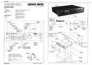
CH 1:ADDING AND DEFINING A <strong>MIDI</strong>PATCHBAYThis technical publication discusses how to use <strong>OMS</strong> <strong>with</strong> <strong>MIDI</strong>patchers (sometimes called patchbays, switchers, or thru boxes) andhow <strong>OMS</strong> automates the selection <strong>of</strong> programs <strong>with</strong>in the patcher. NOTE: This document discusses <strong>MIDI</strong> patcher techniques for bothMacintosh and Windows. Screen-shots from both operating systemsare used interchangeably. Whenever any platform-dependent differencesoccur, they are noted specifically.CONNECTING THE HARDWAREFigure 1 shows an example <strong>of</strong> how to wire a <strong>MIDI</strong> studio containinga standard <strong>MIDI</strong> interface, a <strong>MIDI</strong> patcher, four sound modules, anda computer.Figure 1: Typical Studio <strong>with</strong> <strong>MIDI</strong> PatcherCh 1: Adding and Defining a <strong>MIDI</strong> <strong>Patchbay</strong> <strong>Using</strong> <strong>OMS</strong> <strong>with</strong> a <strong>MIDI</strong> <strong>Patchbay</strong> — pg. 2
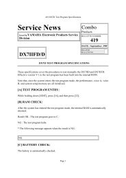
The studio configuration depicted in Figure 1 would be representedin <strong>OMS</strong> Setup as shown in Figure 2:Figure 2: Studio Schematic w/Studio Setup DocumentTo connect a <strong>MIDI</strong> patcher in your <strong>MIDI</strong> studio: Turn <strong>of</strong>f power to your computer, <strong>MIDI</strong> interface and <strong>MIDI</strong> patcher. Connect you computer to your <strong>MIDI</strong> interface. Connect your patcher’s <strong>MIDI</strong> IN jack to your interface’s <strong>MIDI</strong> OUTjack. Similarly, connect your patcher’s like-numbered <strong>MIDI</strong> OUT jack toyour interface’s <strong>MIDI</strong> IN jack. Connect all other <strong>MIDI</strong> devices directly to the <strong>MIDI</strong> patcher. Turn on your patcher, interface, and computer.DEFINING <strong>MIDI</strong> PATCHERS IN <strong>OMS</strong> SETUPThis section explains how to configure your Studio Setup documentto contain a <strong>MIDI</strong> patcher. Before starting, make sure that the currentStudio Setup document is open in <strong>OMS</strong> Setup. It it isn’t, launch <strong>OMS</strong>Setup, then choose File>Open Current Studio Setup.Ch 1: Adding and Defining a <strong>MIDI</strong> <strong>Patchbay</strong> <strong>Using</strong> <strong>OMS</strong> <strong>with</strong> a <strong>MIDI</strong> <strong>Patchbay</strong> — pg. 3
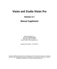
Follow these steps for each <strong>MIDI</strong> patcher in your studio. Choose Studio>New Patcher.The Patcher Info dialog box appears.Figure 3: Typical Patcher Info Dialog Box From the pop-up menus (drop-down list boxes for Windows), selectthe manufacturer and model <strong>of</strong> your <strong>MIDI</strong> patchbay.You can select “other” if you don’t see your patchbay in the list. Use the Ports numerical to enter the number <strong>of</strong> <strong>MIDI</strong> ports (In/Out<strong>MIDI</strong> jack pairs) on your <strong>MIDI</strong> patchbay.<strong>OMS</strong> Setup enters the number automatically when you select aknown patchbay from the Manuf and Model drop-down lists.Figure 3 shows a <strong>MIDI</strong> patcher <strong>with</strong> 20 ports. <strong>Using</strong> the Receive Channels check boxes, select the <strong>MIDI</strong> channelon which your patchbay receives <strong>MIDI</strong> program change information.<strong>OMS</strong> sends patcher program changes when an application (such asGalaxy or another librarian program) needs to establish 2-way communicate<strong>with</strong> a <strong>MIDI</strong> device. This is also the case when <strong>OMS</strong> Setupis in Test Studio mode.Consult your <strong>MIDI</strong> patchbay manual to find out how to set it torespond to <strong>MIDI</strong> program change messages. Some patchers onlyrespond to program change messages on one <strong>of</strong> their input ports—ifthis is true for your patcher, make sure the computer is connected tothat <strong>MIDI</strong> port.Figure 3 shows a <strong>MIDI</strong> patcher that receives <strong>MIDI</strong> program changemessages on <strong>MIDI</strong> channel 13.Ch 1: Adding and Defining a <strong>MIDI</strong> <strong>Patchbay</strong> <strong>Using</strong> <strong>OMS</strong> <strong>with</strong> a <strong>MIDI</strong> <strong>Patchbay</strong> — pg. 4
Click OK.The newly defined patcher will appear in the Studio Setup document.Repeat these steps for every <strong>MIDI</strong> patcher in your studio. When youare finished, choose File>Save to save your work.STUDIOS WITHMORE THAN ONEPATCHERIf your studio contains more than one <strong>MIDI</strong> patchbay, your StudioSetup document will contain multiple patcher icons and theirPatcher Info dialog boxes will contain an additional pop-up menucalled Send program changes to.Most <strong>MIDI</strong> patchers receive program changes only on one <strong>of</strong> their<strong>MIDI</strong> in ports. The Send Program Changes to pop-up menu allowsyou to specify which computer port, and consequently whichpatcher port, receives the program change.SHARING APATCHERBETWEEN TWOPORTSIt’s conceivable that your <strong>MIDI</strong> studio could contain a single patcher<strong>with</strong> <strong>MIDI</strong> connections to two different serial port interfaces (particularlyif you use a Macintosh). If your studio is set up this way, yourStudio Setup document will need to show two patchers.This is easiest to explain by example. Suppose you have the StudioSetup document shown in Figure 4. It represents a single MSB 16/20<strong>MIDI</strong> patcher shared between two serial ports. “MSB 16/20 Modem”and “MSB 16/20 Printer” represent one patcher operating on twoserial ports.Figure 4: One Patcher Defined as TwoCh 1: Adding and Defining a <strong>MIDI</strong> <strong>Patchbay</strong> <strong>Using</strong> <strong>OMS</strong> <strong>with</strong> a <strong>MIDI</strong> <strong>Patchbay</strong> — pg. 5
Since there are two patcher icons, each patcher icon’s <strong>MIDI</strong> DeviceInfo dialog contains a Send program changes to pop-up menu.Figure 5: Send Program Changes to Pop-up MenuIn this example, the Send program changes to pop-up menu allowsyou to choose whether program changes are sent to the MSB 16/20via the computer’s Modem port or its Printer port. Choosing “self”in Figure 5 tells <strong>OMS</strong> to send program changes to the MSB <strong>MIDI</strong> portthat’s connected to the Modem port. Choosing “MSB 16/20 Printer”tells <strong>OMS</strong> to send program changes to the MSB <strong>MIDI</strong> port that’s connectedto the Printer port. NOTE: If you share a single patcher between two serial ports (asshown in the previous example), you must give each patcher aunique name—in this example, we named one patcher “MSB 16/20Modem” and the other, “MSB 16/20 Printer”.Ch 1: Adding and Defining a <strong>MIDI</strong> <strong>Patchbay</strong> <strong>Using</strong> <strong>OMS</strong> <strong>with</strong> a <strong>MIDI</strong> <strong>Patchbay</strong> — pg. 6
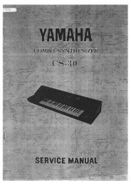
CH 2:CONNECTING <strong>MIDI</strong> DEVICESTO PATCHBAYSFigure 6 illustrates a typical <strong>MIDI</strong> patcher connected to a standardinterface and the devices that are connected to the patcher.Figure 6: Patcher in a Studio Setup Document (Mac Version)STUDIO SETUP PATCHER ANATOMYAs you can see in Figure 6, the Studio Setup document containsnumerous parameters that are associated <strong>with</strong> the <strong>MIDI</strong> patcher.These are: Patcher Icon—You can change this just like any other <strong>MIDI</strong> deviceicon in a Studio Setup document. Patcher Default Program—Every <strong>MIDI</strong> patcher needs one internalprogram that’s designed to 1) transfer <strong>MIDI</strong> data from any <strong>MIDI</strong>controller to your PC, and 2) transfer <strong>MIDI</strong> data from the PC to every<strong>MIDI</strong> device. This is called the “default” program. Set the DefaultProgram numerical to match the <strong>MIDI</strong> program number <strong>of</strong> thepatcher’s internal “default” program. For more information, seePatcher Default Program (pg. 8). Patcher Name—This is the name <strong>of</strong> the <strong>MIDI</strong> patchbay as defined inthe Patcher Info dialog box.Ch 2: Connecting <strong>MIDI</strong> Devices to <strong>Patchbay</strong>s <strong>Using</strong> <strong>OMS</strong> <strong>with</strong> a <strong>MIDI</strong> <strong>Patchbay</strong> — pg. 7
Patcher Port—These numericals correspond to the numbered portson your <strong>MIDI</strong> patchbay. For example, if your Korg M1 is connectedto port 3 <strong>of</strong> your <strong>MIDI</strong> patchbay, set the numerical next to the M1to “3”. For more information, see Patcher Port Assignments (pg. 9). Patcher Program—You should program your <strong>MIDI</strong> patcher suchthat each <strong>MIDI</strong> device has its own patcher program that sends <strong>MIDI</strong>data only to that device and receives <strong>MIDI</strong> data only from that device.Set each Program Number numerical to match the <strong>MIDI</strong> programnumber that does this in the patchbay’s internal memory. For moreinformation, see Patcher Program Assignments (pg. 9).The following sections discuss some <strong>of</strong> these parameters in detail.PATCHERDEFAULTPROGRAMThe small quadrangle <strong>with</strong> the number inside represents thepatcher’s default program number. The default program is that programused by the patcher whenever it’s not routing data from aspecific <strong>MIDI</strong> device to the computer. You need to design a patcherprogram to be your default program and assign it a program changenumber. Your patcher’s default program allows your <strong>OMS</strong> applicationsto send data to any device at any time, so it must:• Connect the computer’s output to all <strong>MIDI</strong> devices connected to thepatcher.• Connect the computer’s input to the controller keyboard.See your <strong>MIDI</strong> patcher manual to learn how to program it and howto assign <strong>MIDI</strong> program change numbers to <strong>MIDI</strong> patcher programs.Look at Figure 7. The M1 is the master keyboard controller. TheMatrix-1000 and Proteus are sound modules. The arrows indicate<strong>MIDI</strong> cable connections. The lines inside the patcher indicate itsdefault program. Notice that <strong>MIDI</strong> data from the computer passesthrough to all devices and that the M1 sends <strong>MIDI</strong> data to thecomputer.ProteusComputerInterfaceMatrix 1000PatcherM1Figure 7: Default Program ExampleCh 2: Connecting <strong>MIDI</strong> Devices to <strong>Patchbay</strong>s <strong>Using</strong> <strong>OMS</strong> <strong>with</strong> a <strong>MIDI</strong> <strong>Patchbay</strong> — pg. 8
To set the patcher default program number in the Studio Setupdocument: Click the number in the quadrangle and type the number <strong>of</strong> yourpatcher’s default program.PATCHER PORTASSIGNMENTSPatchers have ports to which you connect <strong>MIDI</strong> devices. Port numbersare represented by small, boxed numericals in the <strong>MIDI</strong> path toeach device. You must set the Studio Setup document’s port numbersto match each device’s patcher port number. Connect <strong>MIDI</strong> devices to the patcher in the Studio Setup documentso that they mirror your actual connections (as discussed earlier inthis document). Select the patcher port numerical and enter the number <strong>of</strong> thepatcher port to which that <strong>MIDI</strong> device is connected.Figure 8: Setting a Patcher Port NOTE: The numerical range <strong>of</strong> the patcher port assignment correspondsto the number <strong>of</strong> <strong>MIDI</strong> ports entered in the patcher definition. NOTE: If you are using different numbered ports on your patcher for<strong>MIDI</strong> In and <strong>MIDI</strong> Out <strong>of</strong> a single device, you will have to use twoicons to represent the device. This type <strong>of</strong> connection is not recommended.See CH 3: Non-Standard Use <strong>of</strong> Patchers for more details.PATCHERPROGRAMASSIGNMENTSEach device that’s connected to a <strong>MIDI</strong> patcher has a quadrangle toits far left. The numerical inside the quadrangle represents a <strong>MIDI</strong>program change number. You can ignore this section if your <strong>MIDI</strong>patcher does not accept <strong>MIDI</strong> program changes.If you want two-way communication between a <strong>MIDI</strong> device and thecomputer (such as when transferring patch banks between them),you’ll need to program your patcher so that each <strong>MIDI</strong> device has acorresponding patcher program that allows it to send data to, andreceive data from, the computer. See your <strong>MIDI</strong> patcher manual tolearn how to program it and how to assign <strong>MIDI</strong> program changenumbers to <strong>MIDI</strong> patcher programs.Ch 2: Connecting <strong>MIDI</strong> Devices to <strong>Patchbay</strong>s <strong>Using</strong> <strong>OMS</strong> <strong>with</strong> a <strong>MIDI</strong> <strong>Patchbay</strong> — pg. 9
Look at Figure 9. The arrows indicate <strong>MIDI</strong> cable connections. Thelines inside the patcher indicate a patcher program that sends <strong>MIDI</strong>data from the computer to the Proteus and <strong>MIDI</strong> data from the Proteusto the computer. This would be the patcher program for theProteus.ProteusComputerInterfaceMatrix 1000PatcherM1Figure 9: Patcher Program ExampleTo set the patcher program number in the Studio Setup document: Select the number in the quadrangle by clicking it.Figure 10: Setting a Patcher Program Enter the patcher program number. NOTE: <strong>OMS</strong> Setup uses the standard <strong>MIDI</strong> program change numberrange (0-127). Some patchers observe alternate numbering conventions(1-128 or 11-88). If your patcher uses a patch numberingscheme other than 0-127, see its manual to learn the relationshipbetween its internal patch numbering and standard <strong>MIDI</strong> programchange numbers. NOTE: Some patchers receive program changes on only one port—be sure to connect this port to your <strong>MIDI</strong> interface.USING THE TEST STUDIO COMMAND WITH A PATCHERWhen in Test Studio mode, clicking the patcher icon also sends theappropriate two-way communication patcher program. Clicking thepatcher icon recalls the patcher’s default program.Ch 2: Connecting <strong>MIDI</strong> Devices to <strong>Patchbay</strong>s <strong>Using</strong> <strong>OMS</strong> <strong>with</strong> a <strong>MIDI</strong> <strong>Patchbay</strong> — pg. 10
PATCHER DELAYIn the <strong>OMS</strong> Preferences dialog box, there is an item called “Delayafter sending program change to <strong>MIDI</strong> patcher(s)”:You can choose how many milliseconds you want to delay the transfer<strong>of</strong> <strong>MIDI</strong> data after sending a program change to a <strong>MIDI</strong> patcher.This is necessary because <strong>MIDI</strong> patchers take a small amount <strong>of</strong> timeto rearrange their internal connections after receiving a programchange message. <strong>OMS</strong> needs to wait before transmitting so that<strong>MIDI</strong> data following a program change is properly routed and transmittedthrough a patcher. If you are using a <strong>MIDI</strong> patcher and thingsdon’t seem to be working properly, try increasing the delay time. Agood starting place is 50 milliseconds.Ch 2: Connecting <strong>MIDI</strong> Devices to <strong>Patchbay</strong>s <strong>Using</strong> <strong>OMS</strong> <strong>with</strong> a <strong>MIDI</strong> <strong>Patchbay</strong> — pg. 11
CH 3:NON-STANDARD USE OFPATCHERSIn a standard patcher connection, you connect the <strong>MIDI</strong> inputs andoutputs <strong>of</strong> your <strong>MIDI</strong> devices to <strong>MIDI</strong> port pairs on your patcher.Patcher/device connections that deviate from this scheme are called“non-standard”.One possible non-standard patcher connection is shown inFigure 11. Outputs from <strong>MIDI</strong> devices connect to the patcher, butinputs to <strong>MIDI</strong> devices connect to the standard interface. This iswhat the actual cable routing would look like:Figure 11: Actual <strong>MIDI</strong> Cable RoutingCh 3: Non-Standard Use <strong>of</strong> Patchers <strong>Using</strong> <strong>OMS</strong> <strong>with</strong> a <strong>MIDI</strong> <strong>Patchbay</strong> — pg. 12
Here’s what you would do in <strong>OMS</strong> Setup to create thatconfiguration:Figure 12: Equivalent Studio Setup DocumentUse the Studio>Different In/Out Ports option to configure eachdevice as shown.In the example shown in Figure 12, you send program changes to thepatcher, routing <strong>MIDI</strong> to the computer from a particular device.Every device is always available for output from the computer.Ch 3: Non-Standard Use <strong>of</strong> Patchers <strong>Using</strong> <strong>OMS</strong> <strong>with</strong> a <strong>MIDI</strong> <strong>Patchbay</strong> — pg. 13