ASR-10 Operator's Manual - MPCStorageSolution
ASR-10 Operator's Manual - MPCStorageSolution
ASR-10 Operator's Manual - MPCStorageSolution

Create successful ePaper yourself
Turn your PDF publications into a flip-book with our unique Google optimized e-Paper software.
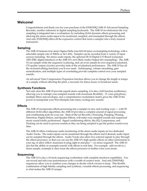
PrefaceWelcome!Congratulations and thank you for your purchase of the ENSONIQ <strong>ASR</strong>-<strong>10</strong> Advanced SamplingRecorder, another milestone in digital sampling keyboards. The <strong>ASR</strong>-<strong>10</strong> revolutionizes the waysampling is integrated into a workstation, by including 24-bit dynamic effects processing andallowing the stereo audio input to be monitored, sampled, and resampled through the effects.And only ENSONIQ offers all the expressive control that turns a sampler into a truly musicalinstrument.SamplingThe <strong>ASR</strong>-<strong>10</strong> features true stereo Sigma-Delta (one-bit) 64 times oversampling technology with aselectable sample rate of 30kHz or 44.1 kHz. Samples can be recorded from a variety of inputsources including: the stereo audio inputs, the optional DI-<strong>10</strong> Digital I/O Board (consumerAES/EBU digital interface) or the <strong>ASR</strong>-<strong>10</strong>’s own Main Audio Output (for resampling). The <strong>ASR</strong>-<strong>10</strong> can sample while the sequencer is playing, and can even sample its own sequencer playback.CD quality output circuitry provides state of the art playback performance. The <strong>ASR</strong>-<strong>10</strong> has allthe on-board editing functions you’ll ever need. Autolooping, volume smoothing, gainnormalization, and multiple types of crossfading provide complete control over your sampledsounds.An advanced Time Compression/Expansion function allows you to change the length or tempoof a sample without affecting the pitch, a necessity for dance music or broadcast needs.Synthesis FunctionsNot only does the <strong>ASR</strong>-<strong>10</strong> provide superb stereo sampling, it is also a full function synthesizer,allowing you to reshape your sampled sounds with maximum flexibility. 31 voice polyphony,multiple filters and envelopes, and a comprehensive modulation matrix gives the <strong>ASR</strong>-<strong>10</strong> thepower to manipulate your WaveSamples into many exciting new sounds.EffectsThe <strong>ASR</strong>-<strong>10</strong> incorporates effects processing into a sampler in new and exciting ways — with 50different 24-bit effect algorithms, the <strong>ASR</strong>-<strong>10</strong> provides a complete arsenal of signal processingand conditioning tools for your use. State-of-the-art Reverbs, Chorusing, Flanging, Phasing,Distortion, Digital Delays, and Speaker Effects, will make your sampled sounds and sequencedmusic sound totally professional. Signal conditioning effects, like EQ, Compression, andDucking can be used to process sounds as they are being sampled to get the perfect sound everytime.The <strong>ASR</strong>-<strong>10</strong> offers continuous audio monitoring of the stereo audio inputs on two dedicatedAudio Tracks. The audio inputs can be monitored through the effects and if desired, audio inputcan be sampled through the effects. Audio Tracks also allow live external signals to play throughthe effects processor, so that you can use the <strong>ASR</strong>-<strong>10</strong>’s high quality effects on other instruments inyour rig, or allow fellow musicians to plug right in and play — no mixer required! The <strong>ASR</strong>-<strong>10</strong>also has the ability to resample sounds with effects in real time. For example: add reverb to adrum sample, resample it, then reuse the effects processor to further color your music.SequencingThe <strong>ASR</strong>-<strong>10</strong> is also a 16-track sequencing workstation with complete mixdown capabilities. Youcan record and edit your performances with a wealth of creative tools. And only ENSONIQsequencers allow you to audition your changes to decide which version to keep. This flexiblecombination of high fidelity sampling and synthesis, versatile effects processing, and sequencingis what makes the <strong>ASR</strong>-<strong>10</strong> unique.i
Preface<strong>ASR</strong>-<strong>10</strong> Musician’s <strong>Manual</strong>Audio Track Recording CapabilityVersion 2 O.S. adds two tracks of digital audio recording capability to the <strong>ASR</strong>-<strong>10</strong>. Audio Trackscan be recorded directly into RAM (RAMTracks) or directly to a SCSI storage device (harddisk, removable media, etc.) via the optional SP-3 SCSI Interface (DiskTracks). Now you cancombine live performances with MIDI sequenced tracks for full production recording within the<strong>ASR</strong>-<strong>10</strong>. Sing, play your guitar, blow your horn — add whatever live performances you wish.Recognizing that you want to get up and running quickly, we strongly recommend that you trythe section titled “An Audio Track Tutorial” in Section 18 — Audio Track Applications to get a feelfor the Audio Track recording process.Support for the Optional DI-<strong>10</strong> Digital I/O Interface<strong>ASR</strong>-<strong>10</strong> Version 2 supports the optional DI-<strong>10</strong> Digital I/O Interface. When installed, the DI-<strong>10</strong>provides direct digital input and output connection to and from the <strong>ASR</strong>-<strong>10</strong> using RCA-typeconnectors. The Digital Output will provide 44.1 kHz digital output of the Main Out mix whenthe current effect uses a 44.1 kHz sample rate. The Digital Input can be used for direct digitalsampling from an external digital audio source at 44.1 or 48 kHz.The Digital Input and Output conforms to the S/PDIF standard (Sony/Phillips Digital InterfaceFormat). S/PDIF is a digital audio communication standard for digital hardware devices. Besure that any digital devices used with the DI-<strong>10</strong> conform to this standard. For more informationabout using the DI-<strong>10</strong> Digital I/O Interface, refer to the DI-<strong>10</strong> <strong>Manual</strong>.Note:If you wish to record the 44.1 kHz digital output of the <strong>ASR</strong>-<strong>10</strong> to a DAT recorder, the DATrecorder must be able to record from its digital input at 44.1 kHz. Some older/consumer DATrecorders do not record at 44.1 kHz as a copy protection scheme: These DAT recorders will notrecord the <strong>ASR</strong>-<strong>10</strong>’s 44.1 kHz digital output.Additional 44.1 kHz Effect AlgorithmsThe O.S. disk also includes 12 additional effect algorithms, designed exclusively for the <strong>ASR</strong>-<strong>10</strong>,that use the 44 .1 kHz system sample rate (note: polyphony is reduced to 23 voices). AudioTracks recorded at the 44.1 kHz sample rate can be output directly from the <strong>ASR</strong>-<strong>10</strong>’s Digital I/OOutput jack (which requires the optional DI-<strong>10</strong> Digital I/O Interface). For a complete descriptionof all the effect algorithms, see later in this document.Clean Up and MaintenanceOnly clean the exterior of your <strong>ASR</strong>-<strong>10</strong> with a soft, lint-free, dry (or slightly damp) cloth. You canuse a slightly dampened cloth (with a mild neutral detergent) to remove stubborn dirt, but makesure that the <strong>ASR</strong>-<strong>10</strong> is thoroughly dry before turning on the power. Never use alcohol, benzene,volatile cleaners, solvents, abrasives, polish or rubbing compounds.About The <strong>Manual</strong>The Musician’s <strong>Manual</strong> is your guide to unlocking the full power of the <strong>ASR</strong>-<strong>10</strong>. At this point,you’re probably anxious to plug in your <strong>ASR</strong>-<strong>10</strong> in and get playing. The rest of this sectioncontains important information about power, grounding, amplification and care of the floppydrive. We recommend that you read through it, and then follow the Tutorial. The Tutorial isdesigned to provide step-by-step procedures for performing basic operations on the <strong>ASR</strong>-<strong>10</strong>.After the initial “I just gotta hear it” phase has passed and you’re ready to utilize the fullpotential of the <strong>ASR</strong>-<strong>10</strong>, please take the time to read through the sections in this manual onsampling, programming, sequencing, effects, and storage. The Musician’s <strong>Manual</strong> is designed tobe used as a reference tool. Both manuals provide valuable information and tips that will speedup the learning process and ensure your maximum enjoyment of this powerful musicalinstrument.ii
PrefaceThank-you again for choosing ENSONIQ. Enjoy the music!iii
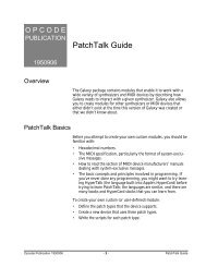
Preface<strong>ASR</strong>-<strong>10</strong> Musician’s <strong>Manual</strong>Power1 2Insert the line cord into the line receptacle on the back of the <strong>ASR</strong>-<strong>10</strong> (2), next to the power switch(1). Plug the other end of the cable into a grounded AC outlet. The proper voltage for your <strong>ASR</strong>-<strong>10</strong> is listed on the Serial Number label on the rear panel. Turn the <strong>ASR</strong>-<strong>10</strong> power on and makesure the display lights up. If not, check your connections and power source.Power — Polarization and GroundingLike many modern electrical devices, your <strong>ASR</strong>-<strong>10</strong> has a three-prong power cord with earthground to ensure safe operation. Some products have power cords with only two prongs and noearth ground. To ensure safe operation, modern products with two-prong power cords havepolarized plugs that can only be inserted into an outlet the proper way. Some products, such asolder guitar amplifiers, do not have polarized plugs and can be connected to an outlet incorrectly.This may result in dangerous high voltages on the audio connections that could cause youphysical harm or damage any properly grounded equipment to which they are connected, suchas your ENSONIQ product.To avoid shock hazards or equipment damage, we recommend the following precautions:• If you own equipment with two pronged power cords, check to see if they are polarized ornon-polarized. You might consider having an Authorized Repair Station change any nonpolarizedplugs on your equipment to polarized plugs to avoid future problems.• Exercise caution when using extension cords or plug adapters. Proper polarization shouldalways be maintained from the outlet to the plug. The use of polarized extension cords andadapters is the easiest way to maintain proper polarity.• Whenever possible, connect all products with grounded power cords to the same outletground. This will ensure a common ground level to prevent equipment damage andminimize hum in the audio output.AC outlet testers are available from many electronic supply and hardware stores. These can beused to check for proper polarity of outlets and cords.ivDisk Care
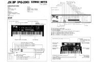
PrefaceGround LoopsSometimes currents flowing through the ground line generate a signal seen by another part of thecircuit sharing the same ground. In other words, if there are two identical signal paths within acircuit, they can form a loop which can result in hum and/or noise. If you are using equipmentthat has 3-prong “grounded” AC power cords, you may suffer from a ground loop resulting fromthe interconnection of this equipment. The following diagram shows how cascading or“chaining” the output of one 3-prong grounded system into the input of another 3-pronggrounded system with a standard unbalanced 2 conductor cord (like a 1/4” guitar cable) canresult in a ground loop.Unbalanced Output to Unbalanced Input.Single conductor shielded cable3-Prong"Grounded"System+ +Earth GroundSIGNAL PATH(circuit ground)>Ground Loop
Preface<strong>ASR</strong>-<strong>10</strong> Musician’s <strong>Manual</strong>AmplificationConnect the Main Audio Outputs of the <strong>ASR</strong>-<strong>10</strong> to the line level inputs of a mixer, instrumentamplifier, stereo, or any other sound system, using 1/4 inch audio cables. If your system isstereo, connect the Left and Right Main Outputs to two channels of your mixer, stereo, etc. If it’smono, use either of the Main Audio Outputs, but make sure nothing is plugged into the otheroutput. For listening through headphones, plug the phones into the rear panel jack markedPhones. If you’re running the <strong>ASR</strong>-<strong>10</strong> through a mixer, in stereo, be sure to pan the left inputchannel on the mixer fully left, and the right input channel fully right.It is a good idea to make sure your audio system is turned off (or down) when makingconnections, to avoid damaging speakers or other components.Note:The <strong>ASR</strong>-<strong>10</strong> outputs are line-level, and are intended to be connected only to line-level inputs,such as those on a mixer, stereo pre-amp, keyboard amp, etc. Connecting the <strong>ASR</strong>-<strong>10</strong> audiooutputs to a mic-level input, such as a guitar amp or the microphone jacks on a tape deck, is notrecommended, and might result in damage to the device input.Move the Volume Slider all the way up. As with any digital musical instrument, the <strong>ASR</strong>-<strong>10</strong> willgive the best results if you keep the Volume Slider full on, and use the volume control on yourmixer or amp to adjust its level.Switch the audio system on, and adjust the amplifier volume for normal listening levels. If youhear no sound while playing the keyboard, switch the audio system off and check yourconnections.Running Your <strong>ASR</strong>-<strong>10</strong> Through a Home Stereo SystemIf you are thinking about amplifying your <strong>ASR</strong>-<strong>10</strong> through your home stereo, a word of caution isin order. A home stereo is great for playing CD’s, albums, tapes — the dynamic range of thesemedia is limited, and your speakers aren’t usually subjected to extreme volume changes andfrequency transients. While the dynamic range of CD’s is significantly greater than LP’s or tapes,the output of a CD player is still conservative compared to the uncompressed, unlimited lineleveloutput of a pro-level keyboard. Running your <strong>ASR</strong>-<strong>10</strong> — or any pro-level keyboardthrough a home stereo at high volume levels can damage your speakers, not to mention theimpedance mis-match this can create. If your only means of amplification is your home stereo,then try to keep your levels on the conservative side.viDisk Care
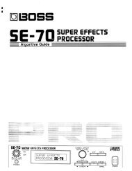
PrefaceCare and Feeding of the Disk DriveThe <strong>ASR</strong>-<strong>10</strong>’s built-in disk drive is used to store all your Instruments, Banks, and Sequencer data,as well as System Exclusive messages from other MIDI devices. The <strong>ASR</strong>-<strong>10</strong> uses a Quad-densitydisk drive that can store 1600 Kilobytes of data on a Double-Sided High-Density (DSHD) 3.5”micro-floppy disk and 800 Kilobytes of data on a Double-Sided Double-Density (DSDD) 3.5”micro-floppy disk. The disks are enclosed in a protective plastic carrier with an automatic shutterto protect the diskette from physical damage. It is important not to alter this carrier in any way.The 3.5” disks have a sliding writeprotectiontab so that you can protectyour sounds and sequences againstaccidental erasure. Sliding the writeprotectiontab in the lower left corner ofthe disk so that the window is closedwill allow you to store information onthe disk. Sliding the tab so that thewindow is open will protect the diskagainst being accidentally reformattedor having files deleted. Double-SidedHigh Density disks can be easilyidentified because they have anadditional window (with no writeprotectiontab) located on the lowerright corner of the disk.Double-Sided High-Density (DSHD)Write Protect TabDouble-Sided Double-Density (DSDD)Write Protect TabDiskWindowNo DiskWindowFloppy disks are a magnetic storage medium, and should be treated with the same care you’dgive important audio tapes. Just as you would use high quality audio tapes for your importantrecording needs, we recommend using high quality floppy disks for your <strong>ASR</strong>-<strong>10</strong>. Here are a fewDo’s and Don’t’s concerning disks and the disk drive.Do’s:• Use either Double-Sided High-Density (DSHD) or Double-Sided Double-Density (DSDD) 3.5inch Micro-floppy disks. Both types are available from almost any computer store and manymusic stores carry them as well.• Keep your disks and the disk drive clean and free of dust, dirt, liquids, etc.• Label your disks and keep a record of what is saved on each.• Only transport your unit with nothing in the drive.Don’t’s:• Don’t use Single-Sided (SSDD or SSSD) disks. These disks have not passed testing on bothsides. While a single-sided disk might work successfully with the <strong>ASR</strong>-<strong>10</strong>, it is possible thatyou will eventually lose important data to a disk error if you try using Single-Sided disks.• Don’t put anything other than a disk or the plastic sheet in the disk drive.• Don’t transport the unit with a disk in the drive.• Don’t expose disks to extremes of temperature. Temperatures below 50˚ F and above 140˚ Fcan damage the plastic outer shell.• Don’t expose your disks to moisture.• Don’t dry your disks in a microwave oven.• Don’t subject disks to strong magnetic fields. Exposure to magnetic energy can permanentlydamage the information on the disk. Keep disks away from speaker cabinets, tape decks,power cables, airline x-ray equipment, power amplifiers, TV sets, and any other sources ofmagnetic energy.• Don’t eject the disk while the drive is operating (i.e. when the disk drive light is on).Disk Carevii
Preface<strong>ASR</strong>-<strong>10</strong> Musician’s <strong>Manual</strong>Backing-up the O.S. DiskSince floppy disks are vulnerable to the affects of magnetic fields, we highly recommend makingback-up copies of your O.S. disk. Doing so can save time and frustration in the unlikely eventthat the O.S. disk becomes damaged. Since the tutorial files and the additional 44.1 kHz effectalgorithms are on the O.S. disk, you will need a HD (high density) disk to save all of theinformation. We’ll use the COPY FLOPPY DISK command to back up the disk. Here’s how:1. Slide open the plastic write-protect tab on the original O.S. disk (you should be able to seethrough the little square hole) so that the disk is write-protected (protected from being writtento). This is an extra precaution to safeguard the data.2. Press Command, then System•MIDI, and scroll to the COPY FLOPPY DISK command.3. Press Enter•Yes.The display shows INSERT SOURCE DISK (the one you want to copy).4. Insert the source disk, then press Enter•Yes.The drive will engage and the display will flash READING SOURCE DISK. Once the drivestops, the display will change to show INSERT DEST DISK.5. Insert the destination disk (the one you want to copy to) and press Enter•Yes.If the destination disk is unformatted, the display will ask ERASE AND FORMAT DISK?Press Enter•Yes to format the disk. When formatting is complete, the drive will engage andthe display will flash WRITING DEST DISK.After writing to the destination disk, the display will read VERIFYING DEST DISK. If thecopy is complete, the display will read DISK COMMAND COMPLETED.If you do not want to copy all of the tutorial files or the 44.1 kHz effect algorithms, use theCommand/System•MIDI, COPY O.S. TO DISK command (as described in Section 2 —System•MIDI).We recommend that you use the copied O.S. disk for daily use, and store the original O.S. disk ina safe place. If your O.S. disk becomes damaged and you do not have a back-up copy made, yourlocal Authorized ENSONIQ Dealer can make a new copy for you (you must supply the disk).viiiBacking-Up the O.S. Disk
PrefaceAccessoriesThese optional accessories are available from your Authorized ENSONIQ Dealer:• OEX-6sr Output Expander — The OEX-6sr gives the <strong>ASR</strong>-<strong>10</strong> six additional outputs, groupedin three stereo pairs in addition to the built-in stereo outputs. Each WaveSample, or an entireinstrument/track can be assigned to any of the stereo pairs and panned within the stereo field.• SP-3 SCSI Kit — This SCSI (Small Computer Serial Interface) allows the <strong>ASR</strong>-<strong>10</strong> tocommunicate with a hard drive, CD ROM player, or computer. Hard drives provide a faster,more convenient way to store instrument, sequencer, bank, and MIDI files. The SP-3 must beinstalled by an Authorized ENSONIQ Repair Station.• DI-<strong>10</strong> Digital I/O Board (S/PDIF) — Allowing digital input and output using RCA-typeconnectors. The DI-<strong>10</strong> must be installed by an Authorized ENSONIQ Repair Station.• Model CVP-1 CV PEDAL — A Control Voltage Foot Pedal which can be assigned as amodulator within the voice section of the <strong>ASR</strong>-<strong>10</strong> or used as a volume pedal.• ENSONIQ Model SW-<strong>10</strong> Dual Foot Switch — Can be used for hands-free patch select control(when plugged into the Patch Select jack) or used for modulation control, voice sustain, orstarting, stopping, and continuing the internal sequencer (when plugged into the Foot Switchjack).• ENSONIQ Model SW-6 Foot Switch — A single damper piano style foot switch, for sustain,or to function as the right patch select button.• CDR Series — These CD ROMs offer a vast array of instruments, banks, and sequence/songarranged in directories by file types. The CDR Series also features Direct Macros, whichallows instant access (direct-dial) to any instrument file.• AS –Series Sound Libraries — The AS sound libraries are designed exclusively for the <strong>ASR</strong>-<strong>10</strong>, provided on five High Density disks.• SL, SLT, and ESS Sound Libraries — The <strong>ASR</strong>-<strong>10</strong> can read all of the disks designed for theEPS Series. These disks offer the largest, most accurate, responsive, and musical sampledsounds available anywhere. These sounds are divided into three separate libraries: SL, aseries of five-disk sets featuring sounds specifically designed for the EPS-16 PLUS, but fullycompatible with the <strong>ASR</strong>-<strong>10</strong>; SLT, a series of ten-disk packs originally designed by top soundprogrammers for the EPS, also compatible with the <strong>ASR</strong>-<strong>10</strong>; and ESS, three-disk “SignatureSeries” sets designed by renowned industry performers and producers like Joey DeFrancesco,Jason Miles, Maurice White, The System, Nile Rodgers, David Hentschel, and others.An Important Note About Non-ENSONIQ Accessories and Your ENSONIQWarrantyENSONIQ highly recommends that users who wish to add SCSI or a Digital I/O Interface to their<strong>ASR</strong>-<strong>10</strong> use ENSONIQ-made accessories. However, for those who wish to purchase a non-ENSONIQ product, there are some important things to know about non-ENSONIQ products andyour <strong>ASR</strong>-<strong>10</strong>’s warranty:• ENSONIQ will not approve any Non-ENSONIQ SCSI kits or Digital I/O Interfaces for the<strong>ASR</strong>-<strong>10</strong>.• If your <strong>ASR</strong>-<strong>10</strong> requires servicing, and a non-ENSONIQ accessory is installed, <strong>ASR</strong>-<strong>10</strong> ownerswill pay a service fee to have it removed so that a technician can diagnose the base unit.• If it is determined that the use of an unapproved Non-ENSONIQ product caused damage,then the repair of that damage is not covered by the ENSONIQ warranty. Any non-ENSONIQ product which requires opening the case must be installed by an AuthorizedENSONIQ Repair Station.• In addition, if it is found that continued use of a non-ENSONIQ product causes damage toyour <strong>ASR</strong>-<strong>10</strong>, any future service that your unit might require may not be covered under theENSONIQ warranty.An Important Noteix
Preface<strong>ASR</strong>-<strong>10</strong> Musician’s <strong>Manual</strong>Need More Help?Whether you’re an aspiring programmer looking for additional information about basic samplingtechniques and MIDI theory, or a professional sound designer working with advancedapplications, you may want more detailed information that is beyond the scope of this manual.The following books can help enhance your understanding of sampling, synthesis, MIDI, andrelated topics. These, in addition to the numerous monthly magazines, provide a wealth ofinformation. While we don’t endorse any one of these publications, we offer this partial list as aresource for you to draw on.The Mix BookshelfFor prices and more information call: 1-800-233-9604MIDIMIDI FOR MUSICIANS, Craig AndertonTHE MIDI MANUAL, David HuberTHE MIDI HOME STUDIO, Howard MasseyTHE NEXT MIDI BOOK, Rychner & WalkerTHE MIDI BOOK, Steve De Furia, Joe ScacciaferroTHE MIDI RESOURCE BOOK, Steve De Furia, Joe ScacciaferroHOW MIDI WORKS, Dan WalkerMIDI SYSTEMS & CONTROL, Francis RumseyUSING MIDI, Helen Casabona, David FrederickMIDI, THE INS, OUTS AND THRUS, Jeff RonaSAMPLINGTHE SAMPLING BOOK, Steve De Furia, Joe ScacciaferroSAMPLING BASICS, Bobby MaestasSYNTHESIZERSGUITAR SYNTH & MIDI, Guitar Player MagazineSECRETS OF ANALOG AND DIGITAL SYNTHESIS, Steve De FuriaSYNTHESIZER PERFORMANCE & REAL TIME TECHNIQUES, Jeff PressingSYNTHESIZER BASICS, Dean FriedmanMUSIC & TECHNOLOGY, H.P. NewquistA SYNTHESIST'S GUIDE TO ACOUSTIC INSTRUMENTS, Howard MasseyAlfred Publishing CompanyFor prices and more information call 1-818-891-5999MIDIADVANCED MIDI APPLICATIONS, GPIBASIC MIDI APPLICATIONS, GPIWHAT IS MIDI?, GPISYNTHESIZERSBEGINNING SYNTHESIZER, GPIPLAYING SYNTHESIZERS, GPISYNTHESIZER PROGRAMMING, GPIHal Leonard PublishingFor prices and more information call 1-414-774-3630MIND OVER MIDI, GPISYNTHESIZER TECHNIQUE (REVISED), GPIx
PrefaceMonthly MagazinesThe following magazines offer many specific articles and columns that can provide a plethora ofuseful information.THE TRANSONIQ HACKERFor prices and more information about this independent news magazine for ENSONIQUsers, call 1-503-227-6848KEYBOARDFor subscription rates and more information call 1-800-289-9919ELECTRONIC MUSICIANFor subscription rates and more information call 1-800-888-5139HOME & STUDIO RECORDINGFor subscription rates and more information call 1-818-407-0744MIXFor subscription rates and more information call 1-800-888-5139EQFor subscription rates and more information call 1-212-213-3444xi
Section 1 — Controls & ArchitectureThis section provides an introduction to the <strong>ASR</strong>-<strong>10</strong>’s many controls and rear panel connections,a conceptual overview of the system, a guide to understanding memory, and a discussion ofediting various types of parameters. We suggest you read this section carefully — it will helpyou get the most out of your <strong>ASR</strong>-<strong>10</strong>.Rear Panel ConnectionsMIDIThruInOutPatch SelectFoot SwitchPedal•CV1 23456 7 81) PowerThe power switch turns the <strong>ASR</strong>-<strong>10</strong> on and off. When you turn the power on, the display lightsup and shows “PLEASE INSERT DISK,” which is the prompt to load the operating system.2) AC Line InThe supplied line cord connects here. The correct voltage for the <strong>ASR</strong>-<strong>10</strong> is on the rear panelalong with the serial number. If you travel, remember the <strong>ASR</strong>-<strong>10</strong> will only operate on the listedvoltage.3) MIDI ThruThis jack “passes on” all MIDI (Musical Instrument Digital Interface) information received by the<strong>ASR</strong>-<strong>10</strong> to other MIDI devices. Information generated by the <strong>ASR</strong>-<strong>10</strong> itself does not go to this jack— the Thru jack merely echoes what comes into the MIDI In jack.4) MIDI InThis jack receives MIDI information from other MIDI instruments or computers.5) MIDI OutThis jack transmits MIDI information generated by the <strong>ASR</strong>-<strong>10</strong> keyboard and/or sequencer toother instruments and computers.6) Patch Select (Foot Switch)If you connect the optional SW-<strong>10</strong> Dual Foot Switch in this jack, it duplicates the function of thePatch Select buttons, allowing hands-free patch select changes. This jack requires a dual footswitch and will not work properly with a single foot switch (SW-2 or SW-6).7) Foot SwitchThis jack supports either one or two foot switches depending on what is plugged into it:• If you plug the ENSONIQ Model SW-2 Foot Switch (which came with your <strong>ASR</strong>-<strong>10</strong>) into thisjack, it will act as a Sustain pedal. Holding it down will cause notes to continue to sustainafter the key has been released.• Or you can connect the optional ENSONIQ Model SW-<strong>10</strong> Dual Foot Switch here. The SW-<strong>10</strong> isa dual (piano-type) foot switch with two separate pedals. When the SW-<strong>10</strong> is connected, theRight Foot Switch will act as a sustain pedal and the Left Foot Switch is assignable.1
Section 1 — Controls and Architecture<strong>ASR</strong>-<strong>10</strong> Musician’s <strong>Manual</strong>Note:If you are using a single foot switch (SW-2 or SW-6), the Edit/System•MIDI, LEFT FOOT SWparameter should be set to OFF. This will prevent unexpected behaviour. Remember that theFoot Switch jack is optimized for use with a dual foot switch (SW-<strong>10</strong>), and when a single footswitch is connected, it behaves like the Right Foot Switch.When the SW-2 is connectedto the Foot Switch jack:When the SW-<strong>10</strong> is connected tothe Foot Switch jack:It acts as theSustain Pedal.The Left Foot Switchis assignable.The Right Foot Switch actsas the Sustain Pedal.A parameter on the Edit/System•MIDI page (press Edit, then System•MIDI, then scroll untilthe display reads “LEFT FOOT SW=OFF”) determines the function of the Left Foot Switch.Tip:The Sustain pedal can be used to dynamically “latch” the current amount of pressure beingexerted on the keyboard. Here’s how:1) Select a sound that responds to pressure. Choose a sustaining sound like an organ.2) Play a key and press into the keyboard until you can hear the pressure modulationaffect the sound of the note.3) Press and hold the Sustain pedal.4) Release the key. You will hear that the sound continues to be modulated by pressureat the depth to which you were pressing.5) Play a different key. Notice that the new note is not modulated. You can now pressinto the keyboard and modulate the new note independent of the note that issustained. When the current pressure output exceeds the latched level, pressure onthe new note will modulate both notes.6) To release the “latched” pressure value on the sustained note, either press the“latched” key again, or release the Sustain pedal.2 Rear Panel Connections
Section 1 — Controls and Architecture8) Pedal•CVThis jack is for connecting an optional ENSONIQ Model CVP-1 Control Voltage Foot Pedal,which is assignable as a modulator to various parameters within the <strong>ASR</strong>-<strong>10</strong>. The pedal givesyou a handy alternative modulation source when, for example, you would want to use the ModWheel but both hands are busy.ENSONIQCVP-1Control Voltage Foot PedalA CV pedal plugged into this jack can also act as a Volume pedal, controlling the volume of thecurrently selected Instrument•Sequence Track(s). A parameter on the Edit/System•MIDI page(press Edit, then System•MIDI, then scroll until the display reads PEDAL=VOLUME MIDI=7),determines whether the CV pedal will act as a modulator or as a volume pedal. Set toPEDAL=VOLUME to use the CV pedal to control volume.Pedal/CV Specs: 3-conductor (Tip= control voltage input, Ring=5<strong>10</strong> ohm resistor to +5 Volts,Sleeve= ground). 36 KOhm input impedance, DC coupled. Input voltage range=0 to 3 volts DC.Scan rate=32mS (maximum recommended modulation input= 15 Hz). For use with an externalcontrol voltage, use a 2-conductor cable with the voltage on the tip and the sleeve grounded.Rear Panel Connections 3
Section 1 — Controls and Architecture<strong>ASR</strong>-<strong>10</strong> Musician’s <strong>Manual</strong>Rear Panel Connections Cont’d.Digital I/OInOutSCSIOutputExpanderMicLineInputLevelAudio InputB/RightA/LeftMain OutRight/MonoLeft/MonoPhones9 <strong>10</strong>11 12 13 1415169) Digital I/O — Input/OutputThe DI-<strong>10</strong> Digital I/O Interface (S/PDIF) provides direct Digital Input and Output connection toand from the <strong>ASR</strong>-<strong>10</strong> using RCA-type connectors. The Digital Output will provide direct 44.1kHz digital audio output of the Main Output mix when the current effect uses a 44.1 kHz samplerate. The Digital Input can be used for direct digital sampling from an external digital audiosource at 44.1 or 48 kHz.The Digital Input and Output conforms to the S/PDIF standard.Note:If you wish to record the 44.1 kHz digital output of the <strong>ASR</strong>-<strong>10</strong> to a DAT recorder, the DATrecorder must be able to record from its digital input at 44.1 kHz. Some older/consumer DATrecorders do not record at 44.1 kHz as a copy protection scheme: these DAT recorders will notrecord the <strong>ASR</strong>-<strong>10</strong>’s 44.1 kHz digital output.<strong>10</strong>) SCSI InterfaceThis space is for the optional SP-3 SCSI kit that allows the <strong>ASR</strong>-<strong>10</strong> to transfer data to and from aSCSI-compatible hard disk, CD ROM player, or exchange information with computers at veryhigh speed.11) Output Expander (AUX 1, 2, 3)This multi-pin connector is used to connect the optional OEX-6sr Output Expander box, whichprovides the <strong>ASR</strong>-<strong>10</strong> with three pairs of stereo outputs (or 6 individual outs) in addition to thebuilt-in stereo outputs. Each WaveSample, or an entire Instrument•Sequence Track, can beassigned to any of the three AUX stereo pairs and can be independently panned within the stereofield.12) Mic/Line SwitchThis switch is used to change between either a mic (up) or a line (down) level input source.13) Input Level Trim ControlThis knob allows you to amplify the level of the external signal source.4 Rear Panel Connections
Section 1 — Controls and Architecture14) Audio Input — B/Right and A/LeftThese jacks are the Right and Left Audio Inputs into the <strong>ASR</strong>-<strong>10</strong> for sampling or Audio Trackmonitoring of external analog audio sources.SPECS: 140 KOhm input impedance, AC coupled. The Audio Inputs have 2 ranges: Line andMic. With the Mic/Line switch set to Line, the<strong>ASR</strong>-<strong>10</strong> will accommodate signals from +15.5dBV (Input Level Trim control fullycounterclockwise) to -16.5dBV (Input Level Trim control fully clockwise). With the Mic/Lineswitch set to Mic, the <strong>ASR</strong>-<strong>10</strong> will accommodate signals from -11.5dBV (Input Level Trim controlfully counterclockwise) to -43.5dBV (Input Level Trim control fully clockwise). Matching theappropriate input level with the correct settings of the Mic/Line switch and Input Level Trimcontrol will bring the external signal source up to clipping level.15) Main Out — Right/Mono and Left/MonoTo operate the <strong>ASR</strong>-<strong>10</strong> in stereo, connect these outputs to two discrete channels of your mixerand pan the mixer channels right and left. Note that either of the audio outputs can be used as amono output. If you want to listen to the output in mono, make sure that only one of the outputjacks is connected.16) PhonesTo listen to the <strong>ASR</strong>-<strong>10</strong> in stereo through headphones, plug the phones into this jack. The phonesoutput contains a mix of the signal from the main outputs. Headphone volume is controlled bythe volume slider on the front panel. Note that plugging headphones into this jack does notautomatically turn off the audio in the right and left outputs.Rear Panel Connections 5
Section 1 — Controls and Architecture<strong>ASR</strong>-<strong>10</strong> Musician’s <strong>Manual</strong>Front Panel ControlsAlmost everything you do on the <strong>ASR</strong>-<strong>10</strong> — whether it’s selecting a sound, editing that sound,adjusting the tuning, etc. — is controlled from the front panel using the following controls:LoadInstrumentEnv 1 Env 2Env 3(Select Preset)Seq•Song1 2 3Pitch Filters AmpCommand456System•MIDILFOWaveLayer(Create Preset)Edit(Directory)789EffectsTrackCancelEnterVolumeData Entry1 2 3 41) Volume SliderThis controls the overall volume of the <strong>ASR</strong>-<strong>10</strong> audio outputs.0NoYes2) Mode ButtonsThese three buttons are the key to finding your way around the <strong>ASR</strong>-<strong>10</strong>. The <strong>ASR</strong>-<strong>10</strong> is always inone of these three Modes — LOAD, COMMAND, or EDIT. The current mode is selected bypressing the appropriate mode button. The highlighted word in the upper left corner of thedisplay tells you which is the current mode.• LOAD mode is the one you will be in most often — since the <strong>ASR</strong>-<strong>10</strong> lets you continue playingwhile loading sounds and sequences, LOAD mode also doubles as the “Performance” mode.When the LOAD indicator is flashing, the display is showing you disk files for loading. Whenthe LOAD indicator is lit but not flashing, the display is showing you the name(s) of theinstruments in the Internal Memory.Tip:In flashing LOAD mode (when the LOAD indicator is flashing), successive presses of theInstrument, Seq•Song, System•MIDI, or Effects buttons will scroll through the available filesof that type on the selected storage device.• COMMAND mode is used to execute a wide variety of commands, such as: savinginstruments, banks, and sequences to disk; copying instruments, layers, and WaveSamplesfrom one internal location to another; creating and modifying sequences and songs; andmanipulating WaveSamples and their loops in various ways... just to name a few.Tip:In COMMAND mode, successive presses of each of the 14 page buttons will scroll through theCommand screens, one at a time.• EDIT mode is used to select and modify a great many variables — or parameters — rangingfrom the volume of a WaveSample, to the velocity response of the instrument, to the MIDI InMode. Edit mode is also the mode in which all sequence recording and mixing is done.Tip:In EDIT mode, successive presses of each of the 14 page buttons will scroll through the Editscreens, one at a time.6 Front Panel Controls
Section 1 — Controls and Architecture3) Page ButtonsWithin each mode, the available disk files, commands, and parameters are organized into Pages.A page is selected by pressing one of these fourteen page buttons. Once you are on the correctpage, you use the Data Entry Controls to scroll through the files, commands or parameters onthe page. A given page will have different functions depending on the current mode. Each modehas a different set of pages available. Not all fourteen page buttons are active in all three modes.The ten numbered page buttons also double as a numeric keypad for “direct-dialing” a given diskfile, command, or parameter or for sending MIDI Program Changes.4) Data Entry ControlsOnce you are in the desired mode and have selected the proper page, you use the controls in thedata entry section to: locate and load the desired file (in Load mode); locate and execute thedesired command (in Command mode); or locate and modify the value of the desired parameter(in Edit mode).• The Data Entry Slider and the Up and Down Arrow buttons will: move through the files onthe current disk or directory (in flashing LOAD mode); change the value of the currentparameter (in Edit mode); or respond when the <strong>ASR</strong>-<strong>10</strong> asks you for further input during theexecution of a command (in Command mode).• The Left and Right Arrow buttons are used primarily to move to the next parameter orcommand on the current page.Tip:To advance by screens (instead of by parameters), while holding down the Right Arrow button,press the Up Arrow button, or while holding down the Left Arrow button, press the DownArrow button.• The Enter•Yes and Cancel•No buttons are used to either proceed with or cancel the functioncurrently showing on the display.Tip:Tip:Tip:When editing any parameter, pressing Cancel•No will reset the parameter to the value it was setto before it was last edited.In Load mode, successive presses of the Cancel•No button will alternate between solid andflashing Load modes.When editing any parameter that has a center value, there is an easy way to reach that value.While holding down the Down Arrow button, press the Up Arrow button, then quickly releaseboth buttons.Parametric ProgrammingThe method used to modify or edit programs, presets and system parameters is called PagedrivenParametric Programming, which sounds like a mouthful, but don’t worry. Once you’vegrasped a few basic concepts you’ll find that operating the <strong>ASR</strong>-<strong>10</strong> is quite simple, given its manycapabilities.It is likely that you have already encountered some form of parametric programming on othersynthesizers or samplers. What this means is that instead of having a separate knob or slider foreach function, you have one master Data Entry Slider and the Up/Down and Left/Right Arrowbuttons, which adjust the value of whichever parameter you select.This approach has many advantages, the most obvious is that it greatly reduces the amount ofhardware — knobs, switches, faders, etc. needed to control a wide variety of functions. If the<strong>ASR</strong>-<strong>10</strong> had a separate control for each function, it would literally have hundreds of knobs.Front Panel Controls 7
Section 1 — Controls and Architecture<strong>ASR</strong>-<strong>10</strong> Musician’s <strong>Manual</strong>Additional Front Panel Controls6785Left RightPeakSignalInput LevelSampleSource SelectFX SelectFX BypassRecordStopPlay1 2 3 4 5 6 7 8A BInstrumentsAudio TracksSequence TracksContinue9<strong>10</strong>115) DisplayThe <strong>ASR</strong>-<strong>10</strong> Display is divided into two main sections: the Indicator Lights in the top half of thewindow and the 22-character Alphanumeric Display at the bottom of the window.Mode IndicatorPage IndicatorSequencerStatusLOAD INST STOPFILE 2GRAND PIANO22-character Alphanumeric DisplayThe indicator lights will tell you which mode the <strong>ASR</strong>-<strong>10</strong> is in (Load, Command, or Edit); whichpage it is on; and the sequencer status (Stop, Play, Record, etc.). The 22-character alphanumericdisplay is used to show you information about specific files, commands, parameters, etc. It willalso ask you for additional input when necessary, such as which track you want to load aninstrument into, or which WaveSample you want to edit.6) Input Level LED MetersThese 2 dedicated Input Level meters provide separate Left/Right metering of the Audio Inputlevels, pre-FX, at all times. The green Signal LEDs light at -24 dB. The red Peak LEDs light at 6dB below clipping.7) Sample•Source Select ButtonThis button is used to initiate sampling (digitally recording sounds) by the <strong>ASR</strong>-<strong>10</strong>. The RecordSource selected on this page will determine the audio signal that will be monitored on the AudioTracks.8 Front Panel Controls
Section 1 — Controls and Architecture8) FX Select•FX Bypass ButtonThis button acts as the “master” control switch for the built-in effects, determining which, if anyeffect will be used and how it will interact with the instruments that reside in the internalmemory. The controls on this page also determine the current sample rate and polyphony.9) Instrument•Sequence Track Buttons — 1 through 8These eight buttons are used to select, deselect, and “stack” the various instruments that areloaded into the internal memory of the <strong>ASR</strong>-<strong>10</strong>. For each of the eight locations, the two LEDsabove the button indicate whether an instrument is Loaded into that location (red LED lit) andwhether it is Selected (yellow LED lit). See “Playing Instruments” later in this section for a fulldiscussion of the Instrument•Sequence Track buttons.Each instrument location is also a sequencer track — that is, whatever is recorded on track 1 of asequence will play the instrument that is loaded into location #1. When you are recording,editing or mixing sequences and songs, you use these buttons to select the current track.<strong>10</strong>) Audio Track Buttons — A and BAudio Tracks are used to record RAMTracks and DiskTracks. The two Audio Track buttonscontrol audio monitoring of the stereo audio inputs through effects (if desired), enabling you tomonitor during sampling, sing along (or play a guitar) to sequencer playback, or record yourperformance to the Audio Tracks. Each Audio Track has its own Edit/Track MIX, PAN, andOUT bus assignment. The signal monitored on Audio Tracks is the signal that will be sampled orrecorded to the Audio Tracks.Each Audio Track button contains 2 LEDs:• The left LED is red, and is labelled “Source Monitor.” When lit, it indicates that the AudioTrack Record Source (set on the Sample•Source Select page, REC SRC parameter) can bemonitored on the Audio Track, and that a voice is being used to monitor this audio signal.When the Source Monitor LED is off, the Audio Track is muted and inaudible.When REC SRC= MAIN-OUT, the audio inputs are disabled, and both Source Monitor LEDsremain off at all times. This happens because REC SRC= MAIN-OUT recording is all <strong>ASR</strong>-<strong>10</strong>generated audio that is routed to BUS1, 2, or 3, and the Source Monitor voices are not neededto monitor this REC SRC, as it is always audible out the Main Outs.• The right LED is yellow, and is labelled “SELECTED.” When lit, it indicates that the track isselected for parameter editing and/or Audio Track Recording, and that the Audio SignalSource being monitored on the track is selected for sampling. When the SELECTED LED isoff, the track’s Edit/(audio) Track parameters cannot be edited, and the Audio Signal Sourcebeing monitored on the track will not be sampled and will not be recorded to Audio Tracks.See Section 12 — Sequencer and Audio Track Concepts for more information on Audio Tracks.11) Sequencer “Transport Controls”These three buttons are used to control the <strong>ASR</strong>-<strong>10</strong>’s internal multi-track sequencer.Front Panel Controls 9
Section 1 — Controls and Architecture<strong>ASR</strong>-<strong>10</strong> Musician’s <strong>Manual</strong>Performance ControllersThe <strong>ASR</strong>-<strong>10</strong> features a number of real-time performance controllers that can modify sounds as youplay for maximum expressiveness. Three of the most important controllers are located to the leftof the keyboard:Patch SelectButtonsPitch BendWheelModulationWheel• PATCH SELECT BUTTONS — These two buttons are used to select alternate groups of voices(called Layers) within a sound. The <strong>ASR</strong>-<strong>10</strong> can be programmed so that the sound changes(sometimes in subtle ways, sometimes radically) when you play notes with one or both PatchSelect buttons held down As you play instruments on the <strong>ASR</strong>-<strong>10</strong>, make sure you explorewhat these buttons do to each sound.• PITCH BEND WHEEL — This wheel bends the pitch of a note up or down. The wheel isnormally centered, where it has no effect on the pitch — moving the wheel up or down willbend the note by the amount specified in the Bend Range parameters contained on theEdit/System•MIDI page (for GLOBAL BEND RANGE) and on the Edit/Pitch page (for anindividual WaveSample’s BEND RANGE).• MODULATION WHEEL — Perhaps the most common use of the Mod Wheel is to addvibrato, but it can also be assigned as a modulator anywhere within the <strong>ASR</strong>-<strong>10</strong> voicearchitecture to alter the pitch, brightness, volume and a great many other aspects of the sound.<strong>10</strong> Performance Controllers
Section 1 — Controls and ArchitecturePressure (After-touch)Another important controller is Pressure. Pressure (often called after-touch) is a modulator thatallows you to change the sound in various ways by pressing down harder on a key or keys afterthe initial keystrike. The <strong>ASR</strong>-<strong>10</strong> keyboard is capable of generating two types of pressure —Channel Pressure and Poly-Key Pressure.Like the mod wheel or foot pedal, pressure is a modulator and can be chosen wherever amodulator is selected in the programming section (see Section 9 — WaveSample and Layer Concepts)of the <strong>ASR</strong>-<strong>10</strong>. Pressure can be assigned to alter the pitch or volume of voices, filter cutofffrequency, LFO rate or depth, pan location, etc.There are two types of Pressure:• Channel Pressure, also called Mono pressure, affects all notes that are playing when you exertpressure on any of the keys. For example, if you play a three note chord, pressing downharder on any of the three notes of the chord will modulate all three notes. This type ofpressure is the more common of the two types.Most MIDI instruments that currently implement pressure send and receive only channelpressure. If you are playing such an instrument from the <strong>ASR</strong>-<strong>10</strong>, you should set the <strong>ASR</strong>-<strong>10</strong>to send channel pressure. (Note that some devices, including all ENSONIQ products, respondto both types of pressure.)• Poly-Key Pressure, also referred to as polyphonic pressure, is a more sophisticated andexpressive type of pressure. Poly-Key pressure affects each key independently. For example,if you play a three-note chord, pressing down harder on any of the three notes of the chordwill modulate only that note. The other two notes will remain unaffected.Each Instrument•Sequence Track can be programmed to generate Poly-Key pressure,channel pressure or none at all. If you wish to change the pressure type for a given track, youcan do so on the Edit/Instrument page.Tip:Poly-Key pressure generates a tremendous amount of data and will consume sequencer memorymuch faster than other types of events, such as notes and program changes. You should turnpressure off when sequencing instruments which do not respond to pressure, such as piano anddrum sounds.About Pressure 11
Section 1 — Controls and Architecture<strong>ASR</strong>-<strong>10</strong> Musician’s <strong>Manual</strong>Architecture“Booting” the <strong>ASR</strong>-<strong>10</strong>Insert the power cord into the line receptacle on the back of the <strong>ASR</strong>-<strong>10</strong>, next to the power switch.Plug the other end of the cable into a grounded AC outlet. The proper voltage for your <strong>ASR</strong>-<strong>10</strong> islisted on the Serial Number label on the rear panel. Turn the <strong>ASR</strong>-<strong>10</strong> power on and make surethe display lights up. If not, check your connections and power source.The <strong>ASR</strong>-<strong>10</strong> Operating System (O.S.) — the computer program that tells the hardware what to do— is “disk based.” This means that each time you turn the <strong>ASR</strong>-<strong>10</strong> on, the first disk you insertmust be one containing an <strong>ASR</strong>-<strong>10</strong> Operating System (see the disk label). This is called “booting”the machine. Insert the disk with the label facing up and the sliding metal door facing away fromyou. The display will read LOADING SYSTEM while the O.S. is being loaded. You shouldalways use the latest (highest-numbered) Operating System. If the first disk you put in the drivedoesn’t contain the <strong>ASR</strong>-<strong>10</strong> Operating System — the display will flash O.S. NOT ON DISK orDISK NOT FORMATTED. Just remove that disk and insert a proper <strong>ASR</strong>-<strong>10</strong> O.S. disk.Note:We recommend that you use a copy of the original O.S. Disk for daily use, and store the originalO.S. Disk in a safe place. For more information, see the Preface.Right after the <strong>ASR</strong>-<strong>10</strong> is finished loading the Operating System, and before it puts itself intoLOAD mode, it will calibrate its keyboard. During calibration the software scans each key andoptimizes its velocity and pressure response. The display will briefly read TUNING KBD -HANDS OFF. It is important that you don’t play or hold down any keys during this time (seebelow).Once it has “booted” the <strong>ASR</strong>-<strong>10</strong> is ready to operate, but it won’t make any sound until youLOAD an instrument into its internal memory and then select that instrument by pressing itsInstrument•Sequence Track button. These functions will be covered later in this section.Keyboard CalibrationEach time you switch it on, the <strong>ASR</strong>-<strong>10</strong> will go through a boot-up routine that includescalibrating the keyboard — a process by which the <strong>ASR</strong>-<strong>10</strong> software is able to scan the entirekeyboard and optimize the response of each key. This ensures that the keyboard is always finetuned for the best possible response. The calibration process only takes about three seconds.Never play the keyboard while it’s calibrating:After you turn on the <strong>ASR</strong>-<strong>10</strong> and insert the Operating System in the drive, the display will showLOADING SYSTEM, then TUNING KBD - HANDS OFF. You should not play the keyboardwhile this message is on the display. After about three seconds, the display will automaticallyswitch to show the instrument files on the current disk and the <strong>ASR</strong>-<strong>10</strong> is ready for use.If you do play the keyboard while it’s calibrating:Playing keys during calibration will cause the display to show KBD FAILED - RETRY? PressEnter•Yes to allow it to calibrate again, taking care not to play keys this time. In short, youshould make it a point not to play keys during the first few moments after turning the unit on.If the KBD FAILED message appears without touching the keys:If the display repeatedly shows KBD FAILED RETRY? even when you are not touching keysduring calibration, this would indicate a hardware problem and the unit should be serviced by anAuthorized ENSONIQ Repair Station.Using the <strong>ASR</strong>-<strong>10</strong> as a sound module only, after getting repeated KBD FAILED messages:If you want to use the unit as a sound module after the display shows repeated KBD FAILEDRETRY? messages, press Cancel•No. This will disable the Poly-Key keyboard completely, butthe <strong>ASR</strong>-<strong>10</strong> will respond normally to all button presses and incoming MIDI information fromanother MIDI instrument.12 Architecture
Section 1 — Controls and ArchitectureMemoryDisk Memory vs. Internal MemoryThe instruments, banks, and sequences that the <strong>ASR</strong>-<strong>10</strong> plays are stored on 3.5” micro-floppydisks. The <strong>ASR</strong>-<strong>10</strong> uses a high-density (HD) drive, allowing you to uses both Double-SidedHigh-Density and Double-Sided Double-Density disks:Disk Type High-Density High-Density Double-Density Double-DensityFormat(Sector Offset)ENSONIQ(offset 0)COMPUTER(offset 1)ENSONIQ(offset 0)COMPUTER(offset 1)Kilobytes 1600 1440 800 720Sample Words 800k 720k 400 360kBlocks 3176 2863 1585 1426A Block is a handy unit that the <strong>ASR</strong>-<strong>10</strong> uses to measure Internal and Disk memory — 1Block=256 sample words; 4 Blocks=1k sample words.Sounds and sequences must be loaded from the disk into the internal memory of the <strong>ASR</strong>-<strong>10</strong>before they can be played. Once it’s loaded into memory, an <strong>ASR</strong>-<strong>10</strong> sound or sequence iscompletely independent of the copy on the disk — you can do anything you want to it withoutharming the version on the disk, unless you intentionally save the changes. You should feel freeto experiment as much as you like with the instrument, layer, and WaveSample parameters ofany sound that came with the <strong>ASR</strong>-<strong>10</strong>. As long as you have it safely on the disk, you can justreload it and start over if your experiments go awry.Important:The data in the <strong>ASR</strong>-<strong>10</strong> internal RAM Memory is not retained when the power is turned off.Anything in memory, whether Instruments, Banks, or sequencer data, must be saved to diskbefore you switch the power off, or it will be gone forever.Warning!If you are unfamiliar with installing SIMMs, or do not want to risk the possibility of causingdamage to the SIMMs or your <strong>ASR</strong>-<strong>10</strong>, we highly recommend having an Authorized ENSONIQDealer install them. We also recommend reading all of the SIMM information before attemptingto install SIMMs in your <strong>ASR</strong>-<strong>10</strong>.Purchasing SIMMsHere is some important information you should know about purchasing the proper SIMMs:• The <strong>ASR</strong>-<strong>10</strong> was designed to use 1m x 8 or 4m x 8 (Macintosh) non-parity SIMMs (not 1m x 9or 4m x 9 parity SIMMs). We highly recommend using this type of SIMMs.• We do not recommend using parity SIMMs (designed for IBM PC compatibles). These SIMMsmay not operate properly, and may cause damage to the <strong>ASR</strong>-<strong>10</strong>.• We recommend using SIMMs with an access speed of 80 nanoseconds or faster.About Memory 13
Section 1 — Controls and Architecture<strong>ASR</strong>-<strong>10</strong> Musician’s <strong>Manual</strong>What is a SIMM?SIMM is an acronym which stands for Single In-line Memory Module. SIMMs have become theindustry standard used by most computers (both IBM and Mac compatible) to expand thecomputer’s memory. Because of this, SIMMs are readily available in most computer softwarestores, and from mail order organizations. The <strong>ASR</strong>-<strong>10</strong> memory, like a computer, is alsoexpanded using SIMMs.Drams (amount varies)AlignmentNotchLatching HoleEdge ConnectorInternal MemoryAs it comes out of the box, the <strong>ASR</strong>-<strong>10</strong> contains 2 MegaBytes or 1 MegaWord of internal memory(a word is one single sample, or 16 bits). That’s enough for 31.5 (mono) or 15.75 (stereo) secondsof sampling at a 29.8 KHz sample rate, or about 400,000 notes of sequencer memory.This internal memory is shared by sounds and the sequencer. The memory is distributeddynamically between instruments and sequences, which means that the more sounds you have inmemory, the less sequencer memory you have, and vice versa.Expanding the <strong>ASR</strong>-<strong>10</strong> MemoryIf you want to expand the memory, the <strong>ASR</strong>-<strong>10</strong> can address up to 16 MegaBytes/8 MegaWords,using industry standard 1m x 8 or 4m x 8 non-parity SIMMs. There are five different memoryallocations, as shown below:SIMMS 1m x 8 (standard) 4m x 8 1m x 8 1m x 8 & 4m x 8 4m x 8SIMMS Used two two four two & two fourMegaBytes 2 8 4 <strong>10</strong> 16MegaWords 1 4 2 5 8Blocks 3,800* 16,000* 7,900* 20,000* 31,000** Actual block count may vary due to different O.S. Versions.Accessing SIMMsTo access the SIMMs in your <strong>ASR</strong>-<strong>10</strong>, make sure all cables, especially the power cable, areunplugged from the <strong>ASR</strong>-<strong>10</strong>. Turn the unit upside down on a soft surface with the keys facingaway from you. Remove the two screws holding the trap door and remove the trap door fromthe bottom of the <strong>ASR</strong>-<strong>10</strong>. As it comes from the factory, the <strong>ASR</strong>-<strong>10</strong> would look like thisunderneath the trap door:Move jumper whenadding expansion memoryEXPSTDMEM EXP JMPStandard SIMM SlotsJumper is connected forSTANDARD SIMM Memory.Move to the other pins whenusing Expansion SIMM Slots.Two 1-MegaByte SIMMsExpansion SIMM SlotsExpansion slots are empty14 About Memory
Section 1 — Controls and ArchitectureYou will notice that there are two slots with SIMMs installed, and two slots that are empty.These empty slots are called Expansion SIMM Slots, and are used for adding additional SIMMs(when expanding the memory). Directly above the Standard SIMM Slots, you will find theMemory Expansion Jumper.About the Memory Expansion JumperThe Memory Expansion Jumper allows you to access the information in the Expansion SIMMSlots. It must be moved to the EXP (Expansion) pins in order for any SIMMs plugged into theexpansion slots to be recognized. If you do not have any SIMMs plugged into the Expansionslots, the Memory Expansion Jumper must be installed on the STD (Standard) pins, or the <strong>ASR</strong>-<strong>10</strong>will not boot up (display will be blank).Installing SIMMsMemory is user-installable in 1, 2, 4, 5, and 8 MegaWord configurations, with 1 and 4 MegaByteSIMMs, as shown below. There are only five possible memory configurations available on the<strong>ASR</strong>-<strong>10</strong>, as shown in the diagram:1 MegaWordJumper is connectedto STD (Standard) pins2 MegaWordsJumper is connectedto EXP (Expansion) pins4 MegaWordsJumper is connectedto STD (Standard) pins(as shipped from the factory)Two1-MegaByteSIMMs(Standard Slots)ExpansionslotsemptyFour1-MegaByteSIMMsTwo4-MegaByteSIMMs(Standard Slots)ExpansionSlotsempty5 MegaWordsJumper is connectedto EXP (Expansion) pins8 MegaWordsJumper is connectedto EXP (Expansion) pinsTwo4-MegaByteSIMMs(Standard Slots)Two1-MegaByteSIMMs(Expansion Slots)Four4-MegaByteSIMMsTHESE ARE THE ONLY CONFIGURATIONS THAT WILL WORK PROPERLY! Any otherconfigurations will not yield the maximum memory available, or provide the optimalperformance.About Memory 15
Section 1 — Controls and Architecture<strong>ASR</strong>-<strong>10</strong> Musician’s <strong>Manual</strong>About the SIMM SocketThe SIMM socket uses the pins on the end of the latching posts to hold the SIMM in place. Thealignment notch on the SIMM prevents it from being installed backwards. Once installed, theretaining posts hold the SIMM in place securely, preventing it from dropping out of the socketinside the <strong>ASR</strong>-<strong>10</strong>.<strong>ASR</strong>–<strong>10</strong> SIMM SocketRetaining PostLatching PostsRetaining PostTo Remove a SIMM from a SIMM Socket:Bend the two retaining posts out of the way…just far enough to remove the SIMM• Carefully spread open the retaining posts found on each end of the SIMM. Only spread theposts as far apart as needed to clear the board; these posts can easily break if too much force isapplied. If broken, it will be very difficult to secure a new SIMM back into that socket. Wesuggest spreading one post at a time; that way it’s easier to control the amount of pressurebeing applied to remove the SIMM.• Once the retaining posts are out of the way, tilt the SIMM toward you, and lift up and out ofthe socket.To Install a SIMM into a SIMM Socket:SIMM Installation - Side ViewPushPress until SIMMlocks into positionStep 1 Step 2• Place the connector edge of the SIMM into the SIMM Socket, pressing down slightly. Thelatching holes on each end of the SIMM will line up with the latching posts when the SIMM isseated properly.• Tilt the SIMM back into the socket until the retaining posts snap in front of the SIMM. Aproperly installed SIMM should look like this:16 About Memory
Section 1 — Controls and ArchitectureProper SIMM InstallationRetaining PostRetaining Post• Reinstall the trap door with the original screws. To verify that you’ve expanded your memorycorrectly, after powering up the <strong>ASR</strong>-<strong>10</strong>, press Edit, then System•MIDI and scroll until thedisplay shows FREE SYSTEM BLOCKS= (expanded memory amount in blocks). See thememory allocation chart (found earlier) for the proper number of blocks for eachconfiguration.WarningThe <strong>ASR</strong>-<strong>10</strong> was designed to use 1m x 8 or 4m x 8 non-parity SIMMs (not 1m x 9 or 4m x 9 paritySIMMs). We do not recommend using parity SIMMs. These SIMMs may not operate properly,and may cause damage to the <strong>ASR</strong>-<strong>10</strong>.Important Information about SIMMs• When adding memory, only install D-RAM SIMMs in the expansion slots. The <strong>ASR</strong>-<strong>10</strong> willnot accept static RAM or ROMs.• If SIMMs are installed in a less than optimal configuration, the display will read SIMMS INWRONG SOCKETS after booting. If this message is displayed, you should power off andcheck the SIMMs configuration. Here is a example of what could be the most likelyinstallation mistake:Jumper is connectedto EXP (Expansion) pinsTwo1-MegaByteSIMMs(Standard Slots)Two4-MegaByteSIMMs(Expansion Slots)Incorrect ConfigurationThis configuration can cause continuousnoise and distortion on sounds or whensampling/monitoring Audio Tracks.• Any configuration which does not use two or four SIMMs will not work (the system will noteven boot up).• Any combination of SIMMs in which there are two different kinds of SIMMs in the standardslots and/or two different kinds of SIMMs in the expansion slots will not work properly. Thefollowing diagram shows some examples of incorrect configurations:Incorrect Configurations1-MegaByte SIMM4-MegaByte SIMM4-MegaByte SIMM1-MegaByte SIMM4-MegaByte SIMM1-MegaByte SIMMStandardSlots4-MegaByte SIMM1-MegaByte SIMM4-MegaByte SIMM1-MegaByte SIMM1-MegaByte SIMM4-MegaByte SIMMExpansionSlots• These incorrect configurations of 1 and 4 MegaByte SIMMs could produce inaccurateAbout Memory 17
Section 1 — Controls and Architecture<strong>ASR</strong>-<strong>10</strong> Musician’s <strong>Manual</strong>information concerning the number of blocks, or noise and distortion.• If the jumper is not moved from the “STD” position to the “EXP” position, no memory in theexpansion slots will be recognized. The wrong number of blocks will be displayed on theEdit/System•MIDI page.• If the jumper is moved from the “STD” to the “EXP” position and there are no SIMMs in theexpansion slots, the system will not boot up (display will be blank).• 1m x 9 or 4m x 9 parity SIMMs (for IBM PC compatibles) should not be used. Only 1m x 8 or4m x 8 (Macintosh) SIMMs should be used.Troubleshooting Memory ExpansionIf the correct number of blocks is not displayed on the Edit/System•MIDI page:1. Make sure that there is no mix-up between 4m x 8 and 1m x 8 SIMMs (or that the store did notsell you the wrong parts).2. Check that the jumper is in the correct position.3. Check that you are using one of the five proper configurations. Improper configurations maywork, but they will not work properly.Make sure that you are careful when removing the SIMMs. If the plastic retaining posts arebroken, the SIMMs will not stay in place, and the main board will have to be replaced at anAuthorized ENSONIQ Repair Station (a costly error).An Important Note About ElectroStatic DischargeSIMMs are susceptible to ElectroStatic Discharge (ESD) commonly known as “static.”ElectroStatic Discharge can destroy or damage SIMMs. In order to minimize the possibility ofcausing ESD damage, here are some procedures you can follow when installing SIMMs:1. Before installing SIMMs, you should be grounded by using a ground strap to discharge anystatic electric charge built up on your body. The ground strap attaches to your wrist and aground source allowing your hands to be free to work.2. Avoid any unnecessary movement, such as scuffing your feet when handling SIMMs, sincemost movement can generate additional charges of static electricity.3. Minimize the handling of the SIMMs. Keep them in their static free packages until needed.Only transport or store the SIMMs in their protective packages.4. When handling the SIMMs, avoid touching the connector pins. Try to handle the SIMMs bythe edges only.If you have any questions concerning the use of SIMMs, the <strong>ASR</strong>-<strong>10</strong>, or for additional technicalsupport, please contact ENSONIQ Customer Service at (6<strong>10</strong>) 647-3930 Monday through Friday9:30 a.m. to 12:15 p.m. and 1:15 p.m. to 6:30 p.m. Eastern Time.18 About Memory
Section 1 — Controls and ArchitectureAbout InstrumentsWe refer to <strong>ASR</strong>-<strong>10</strong> sounds as Instruments. A grand piano, an electric bass, a multi-sampled drumset, a complete string section — each of these would be an example of an instrument. You canload up to eight instruments into the <strong>ASR</strong>-<strong>10</strong>, memory permitting, and have instant access to anyor all of them.Each instrument contains four different Patches that are selected with the Patch Select buttons.These patches allow a single instrument to have four different inflections, voicings, tunings, orsynth-type program variations all available at the press of a button.An instrument can be any size (within the limits of memory) — one instrument might consist of asingle WaveSample that plays over the entire keyboard, while another might have as many 127different WaveSamples.For controlling remote devices, you can create an instrument that contains no samples at all andassign it to play only out MIDI, on a particular MIDI Channel.Loading an InstrumentYou can load up to eight different instruments into the <strong>ASR</strong>-<strong>10</strong> at once (within the limits ofmemory). First, insert a disk containing one or more instrument files into the disk drive.• Press Load. The LOAD indicator flashes.• Press Instrument. The display looks like this:LOAD INST STOPWhen the LOAD indicator is flashing, the <strong>ASR</strong>-<strong>10</strong> is showing you disk files (think of it as aquestion mark — the <strong>ASR</strong>-<strong>10</strong> is saying “Load the file showing on the display?”). Pressing theUp/Down Arrow buttons takes you through the files on the disk. If there are none, the displaywill read “NO INST OR BANK FILES.”Whenever a disk file is displayed as above, you can press the Left or Right Arrow button to seethe size of that file in Blocks (a Block is 256 samples; 4 Blocks=1K sample words). Press the Leftor Right Arrow button again to return to the file name.• Use the Data Entry Slider or the Up/Down Arrow buttons to view the various instrument fileson the disk. Each file has its own File Number. When an instrument file is showing, the INSTindicator is lit. The BANK Indicator will light when a bank file is showing.• Find the instrument you want to load, and press Enter•Yes. The display will say PICKINSTRUMENT BUTTON. The <strong>ASR</strong>-<strong>10</strong> is asking in which instrument location you want toload the sound into.• Press any of the eight Instrument•Sequence Track buttons. The <strong>ASR</strong>-<strong>10</strong> will beginimmediately loading the instrument into the selected location. The display reads LOADINGFILE… and the left red LED flashes while the instrument is being loaded.About Instruments 19
Section 1 — Controls and Architecture<strong>ASR</strong>-<strong>10</strong> Musician’s <strong>Manual</strong>LOAD INST STOPOnce the instrument has been loaded, the display briefly shows “FILE LOADED.” The left redLED above the Instrument•Sequence Track button stops flashing and remains solidly lit,indicating that there is now an instrument loaded in that location which can be selected bypressing that button.If you tell the <strong>ASR</strong>-<strong>10</strong> to load an instrument into a location that already has an instrument loaded(left red LED lit), the new instrument will be loaded into that location and the one that was therewill be automatically deleted.If You Run Out of System MemoryYou might have to delete an instrument(s) before loading the new one. If there are already one ormore instruments loaded into the <strong>ASR</strong>-<strong>10</strong>, there might not be enough free memory to load thenew one. In this case, the display will say PICK INST TO DELETE. At this point you have threechoices. You can:1. Press any loaded Instrument•Sequence Track button. That instrument will be deleted frommemory and the new one will be loaded; or,2. Press Enter•Yes. The <strong>ASR</strong>-<strong>10</strong> will delete an instrument (or instruments, as needed) for you,starting from the highest-numbered one in memory; or,3. Press Cancel•No. The load command will be canceled with no harm done.Note:You can continue to select and play existing instruments while the new one loads. No more“down-time” waiting for the next sound to load. With the <strong>ASR</strong>-<strong>10</strong>, you can be loading the nextsound you need while continuing to play the currently selected sound.Deleting an Instrument from the Internal MemorySometimes you will want to delete an instrument from memory — to free up some memory forsampling, for instance. Make sure you have saved the instrument to disk before deleting it.Here’s how:• Verify that the instrument you want to delete is selected.• Press Command, then Instrument.• Press the Right Arrow button repeatedly until the display reads DELETE INSTRUMENT.• Press Enter•Yes. The display asks DELETE ?• Press Enter•Yes (or press Cancel•No to abort the procedure).Tip:There is a “shortcut” method for deleting an instrument from internal memory. First, press theInstrument•Sequence Track button of the instrument you would like to delete. Then, whileholding down the Instrument•Sequence Track button, press Cancel•No.20 About Instruments
Section 1 — Controls and ArchitectureAbout BanksBanks provide a way to load a whole group of instruments and sequences into the <strong>ASR</strong>-<strong>10</strong> with afew button presses. When you save a bank to disk, it is like taking a “snapshot” of the contents ofthe <strong>ASR</strong>-<strong>10</strong> Internal memory — the bank file contains information about which instruments areloaded into which of the eight Instrument•Sequence Track locations, and which song andsequences (if any) are currently loaded in Internal Memory. When you load a bank, the <strong>ASR</strong>-<strong>10</strong>will set up Internal Memory in the same state it was in when you saved the bank file, loadingthose instruments into the same locations and, if you choose, loading the song with its relatedsequences. A bank will also save any Performance Presets you have created.For example, you might have a piano loaded into Instrument•Sequence Track 1, a bass inInstrument•Sequence Track 2, and drums in Instrument•Sequence Track 3, and you havecreated a number of Performance Presets containing different keyboard configurations of thoseinstruments. Let’s say you also have in memory a song, which is composed of 12 sequences. Ifyou now save the contents of memory as a bank, you can later call up this exact setup by loadingthe bank.The bank file on a disk doesn’t contain the actual instrument and sequence files — it is just a setof instructions telling the <strong>ASR</strong>-<strong>10</strong> what files to load and where to load them. All the instrumentsand the song in a bank must be saved to disk individually before saving the bank.Note:Any instruments already loaded into locations not used by the bank will be left intact (memorypermitting). You can select and play such instruments while the bank loads.To Load a Bank• Press Load, then Instrument.• Use the Up/Down Arrow buttons to view the different files.LOAD INST STOPBANKFILE 4 SOUND BANK 1When a bank file is showing, the BANK indicator lights on the display along with the INSTindicator.• Once a bank file is showing, press Enter•Yes. The <strong>ASR</strong>-<strong>10</strong> will begin loading the instrumentsand the song data. As it loads each instrument the display tells you what it’s doing. As soonas any of the instruments are finished loading, you can select that instrument and play whilethe rest of the bank loads.At some point in the loading process, you may encounter the following message:LOADINSTSTOPBANKINSERT -ENTERThis prompt is informing you that an instrument or song saved as part of the bank is on adifferent disk than the disk currently in the drive. When this occurs:• Eject the current disk in the disk drive and replace it with the disk that matches the Disk LabelID requested by the <strong>ASR</strong>-<strong>10</strong>.About Banks 21
LSSection 1 — Controls and Architecture<strong>ASR</strong>-<strong>10</strong> Musician’s <strong>Manual</strong>• Press Enter•Yes. The <strong>ASR</strong>-<strong>10</strong> will resume loading until completed, or until the point when itneeds another disk.• When it has finished loading the instruments, the <strong>ASR</strong>-<strong>10</strong> will load the song (if any) and thenset up any copied instruments included in the bank.Playing Instruments• First, press Load until LOAD is solidly lit in the display to make sure you are in LOAD Mode.Now we’ll look at the eight Instrument•Sequence Track buttons and how they function inLOAD Mode.12345678Instrument•Sequence Track ButtonsThese buttons represent a location or “slot” into which an instrument can be loaded. The twoLEDs above each button tell you if there’s an instrument loaded into that location and whetherit’s selected, deselected or “stacked.”• The red LED lights to indicate that an instrument is loaded into that location and can beselected by pressing that button. In the illustration above, we see that instruments are loadedinto locations 1, 2, 3, and 4. If none of the red LEDs are lit, no instruments are loaded. The redLED flashes while an instrument is being loaded from disk.• The yellow LED lights when the instrument is selected (i.e. active on the keyboard). You selectan instrument by pressing its Instrument•Sequence Track button. Pressing the button asecond time “deselects” the instrument, turning off the yellow LED. In the illustration,Instrument #2 is selected. If none of the yellow LEDs are lit, that means that no instrumentsare selected, and playing the keyboard won’t make any sound.• The yellow LED flashes when the instrument is “Stacked” with one or more instruments. Aninstrument that is stacked will play simultaneously with any other instruments that areselected or stacked. You stack an instrument by pressing its button twice in rapid succession (or“double-click” on the Instrument•Sequence Track button, to borrow a term from thosecomputers that use a “mouse”). In the illustration above, Instrument•Sequence Track # 3 isstacked with Instrument•Sequence Track #2. You will hear both instruments when you playthe keyboard (wherever their keyboard ranges overlap, that is).• Select a loaded instrument (one whose red LED is lit) by pressing its Instrument•SequenceTrack button. The display now looks like this:LOAD INSTSTOPOnce you have loaded one or more instruments, select the instrument you want to play bypressing the appropriate Instrument•Sequence Track button. The LOAD indicator stopsflashing, and the <strong>ASR</strong>-<strong>10</strong> shows you the name of the selected instrument, and its volume setting.You can adjust the volume of the instrument with the Data Entry Slider or the Up/Down Arrowbuttons. This lets you easily balance the levels of several instruments when splitting thekeyboard or stacking sounds. If any other instruments are loaded, you can select them in thesame way and adjust their volumes. Each time you select an instrument, its name and volumesetting will appear in the display.22 About Banks
Section 1 — Controls and ArchitectureNote:Tip:Tip:Instruments can be played from an external MIDI controller, without being selected, whenEdit/System•MIDI, MIDI IN MODE=MULTI or MONO-B see Section 2 — System•MIDI fordetails.When TRANSMIT ON = INST CHAN, on the Edit/System•MIDI page, editing the VOLUMEvalue will transmit MIDI Volume messages (Controller #7) on the selected Instrument•SequenceTrack’s MIDI OUT CHANNEL (on the Edit/Instrument page).To adjust the volume of each loaded Instrument without selecting them, first select oneinstrument, and then use the Left/Right Arrow buttons to view the volumes of the otherInstruments that are loaded.• Try selecting different instruments. Try “double-clicking” to stack instruments. Click once ona selected or stacked instrument to deselect it.• Pressing the Load button again returns you to viewing disk files (LOAD flashing). You canalso press Cancel•No to toggle back and forth between looking at disk files (LOAD flashing)and looking at instruments in the internal memory (LOAD indicator lit but not flashing).Keyboard Range (How Instruments Share the Keyboard in Load Mode)Whenever the <strong>ASR</strong>-<strong>10</strong> is in Load Mode (which is the normal performance mode) you are notlimited to one instrument on the keyboard at a time (or two, or three for that matter). Eachinstrument has a Keyboard Range, which is the section of the keyboard that it will occupy whenselected.The range of an instrument can be as much as the full 127 keys of the MIDI Specification (forplaying the <strong>ASR</strong>-<strong>10</strong> from an external controller via MIDI) or as little as a single key. Up to eightinstruments can inhabit the keyboard in a way that might be termed a “Pile o’ Instruments.”Imagine four pieces of paper, each a different size, piled on top of each other:1234In the picture above, sheet #2 is on top of the pile — all of it is showing. The other three sheetsare partially covered up. Now suppose we could magically bring sheet #3 up to the top of thepile. The pile would look like this:Playing Instruments 23
Section 1 — Controls and Architecture<strong>ASR</strong>-<strong>10</strong> Musician’s <strong>Manual</strong>1234Now all of #3 is showing:Numbers 1, 2 and 4 are partiallyshowing, partially covered up.If we now bring #4 to the top ofthe pile, Numbers 1 and 2 arestill partially visible, but #3 iscompletely covered up.1234So it is with instruments loaded into the <strong>ASR</strong>-<strong>10</strong> in Load mode. When you select an instrument,it is brought to the top of the pile. That is, you will hear the most recently selected instrument overits whole range when you play the keyboard. Any previously selected or stacked instrumentswill be “covered up” wherever their ranges overlap with that of the newly selected one.Wherever an instrument is not “covered up,” it will continue to play on the keyboard. So youcan see that “splitting” the keyboard is as easy as selecting two or more instruments withdifferent (or overlapping) ranges.• All instruments that are selected (yellow LED lit) are “on the pile,” even if they are partiallycovered up by another instrument.Now let’s try the “sheets of paper” analogy in terms of instruments on the keyboard. Supposeyou have two instruments loaded into the <strong>ASR</strong>-<strong>10</strong>:• Instrument #1 is a piano sound, whose range is the entire keyboard;• Instrument #2 is a bass sound, whose range is only the bottom two octaves.The ranges of the two instruments can be shown like this:Instrument #1 — PianoInstrument #2 — Bass24 Keyboard Range
Section 1 — Controls and ArchitectureIf you select the piano, it will play over the whole keyboard, covering up the bass entirely:BassPianoNow you select the bass. This brings it to the top of the pile, and it covers up the piano, but onlyin the region where their ranges overlap (the bottom two octaves):BassPianoIf you play now, you will hear the bass in the bottom two octaves and the Piano over the rest ofthe keyboard. If you deselect the bass (by pressing its instrument button again) its yellow LEDgoes out and it returns the whole keyboard range to the piano.This same logic applies no matter how many instruments are loaded and selected. Whicheverone you select comes to the “top of the pile.”Note:The “Pile” described here only exists in Load Mode. In Edit and Command modes, only oneinstrument can be selected at a time.Stacking InstrumentsWith either the bass or the piano selected, double-click the other Instrument•Sequence Trackbutton. Now in the lower two octaves you hear the bass and the piano.Bass and Piano StackedInstruments that you “stack” by double-clicking their instrument buttons will play simultaneouslywith whatever other instruments are on the pile. Selecting another instrument (by pressing itsInstrument•Sequence Track button and not by double-clicking), will bring that instrument tothe top, covering up any stacked instruments as well as any selected ones. Up to all eightinstruments can be stacked at once.Additional Notes:• Whenever a selected instrument is covered up completely by the selection of another, itsyellow LED goes out — it is automatically deselected.• Up to all eight instruments can be selected and can play on some part of the keyboard at once,as long as none is covered up completely.• You can reset any instruments key range. This is done on the Edit/Instrument page.Keyboard Range 25
Section 1 — Controls and Architecture<strong>ASR</strong>-<strong>10</strong> Musician’s <strong>Manual</strong>Loading Sequencer DataThere are two ways that <strong>ASR</strong>-<strong>10</strong> Sequencer data can be stored on a disk:• SONG File. A song file contains a song and all its related sequences. Loading a song file fromdisk will completely erase the current contents of the <strong>ASR</strong>-<strong>10</strong> sequencer memory, replacingwhatever is there with the song and sequences from the disk file.• SINGLE SEQUENCE File. This type of file contains just one sequence. Loading a singlesequence file will not erase the sequencer data already in memory — the new sequence simplybecomes one more sequence in the internal memory which can be selected or used as a step ina song. There can be up to 80 sequences in memory at once.Loading a Song or a Single Sequence from DiskBoth types of sequencer files are accessed from the Load/Seq•Song page.• Press Load, then press Seq•Song.The LOAD indicator flashes, meaning that the <strong>ASR</strong>-<strong>10</strong> is showing you disk files.• Press the Up or Down Arrow button until the file you want to Load is showing on the display:LOADSEQSONGSTOPFILE 6BLUES IN FWhen a Song file is showing, the SONG indicator lights next to the SEQ indicator.LOADSEQSTOPFILE 8FIRST VERSEWhen a single Sequence file is showing, only the SEQ indicator lights.• Press Enter•Yes to load the sequencer file showing on the display. After you have loaded asong or sequence, it is automatically selected.Important:Remember that loading a song or sequence does not ensure that the right instruments are loadedinto the proper Instrument•Sequence Track locations. Each track of each sequence will playwhatever instrument is in that location at the time. The way to make sure everything is in theright place is to save the contents of memory (including the song) as a bank.26 About the Sequencer
Section 1 — Controls and ArchitectureSelecting a Sequence/SongPress the Edit button, then the Seq•Song button. The following screen will appear:EDITSEQSTOPCurrent Sequenceor SongBar and Beat Location withincurrent Sequence or SongThis screen is where you select a sequence or the song. With the selected sequence or songunderlined (as shown above), use the Up/Down Arrow buttons or the Data Entry Slider to selecta different sequence or song. You can always get back to this screen by double-clicking theSeq•Song button (when in Edit mode). The display will indicate whether a song is selected:This will appear when a Songis selected.EDITSEQSONGSTOPPlaying a Sequence/SongTry selecting a sequence, and pressing the Play button in the sequencer section, to the right of thedisplay. The selected sequence will begin to play.While one sequence is playing you can select another one. You will see the name of the newsequence in the display, but the original one will continue to play. When the first sequence isfinished, the sequencer will switch to the new sequence, and it will play. In this fashion you canstring sequences together in real time, as they play.Press the Stop•Continue button or the Left Foot Switch to stop the current sequence.About the Sequencer 27
Section 1 — Controls and Architecture<strong>ASR</strong>-<strong>10</strong> Musician’s <strong>Manual</strong>Saving Sequencer DataSaving a Single Sequence to DiskUse the SAVE CURRENT SEQUENCE command to save a single sequence.• On the Edit/Seq•Song page, select the sequence you want to save.• Insert a formatted disk into the drive.• Press Command, then press Seq•Song.• Press the Left or Right Arrow button until the display reads SAVE CURRENT SEQUENCE.• Press Enter•Yes.• Edit the Sequence Name (if needed):CMDSEQSTOPThe display shows the current name of the sequence, with a cursor (underline) beneath the firstcharacter. If you want to give the sequence a new name, do so at this time. Use the Data EntrySlider or the Up/Down Arrow buttons to change the underlined character, then press theLeft/Right Arrow buttons to move the underline. Repeat until the display shows the name youwant (if you don’t need to rename the sequence, just skip this step).• Press Enter•Yes. The display will read SAVING while the sequence is beingsaved.• If there is already a sequence file with the same name on the disk, the display will ask DELETEOLD VERSION? Press Enter•Yes to save the sequence, replacing the one on the disk. Orpress Cancel•No to abort the procedure.• If there is not enough free space on the disk, the display will say NOT ENOUGH DISKSPACE. Save the sequence to another disk (or delete some files from the disk).• If you try to SAVE CURRENT SEQUENCE while the song is selected, the <strong>ASR</strong>-<strong>10</strong> will notexecute the command, responding USE SAVE SONG + ALL. Again, make sure the sequenceis selected before trying to save it.28 About the Sequencer
Section 1 — Controls and ArchitectureSaving a Song (along with all Sequences) to DiskOnce you have created a song or made changes to an existing one, you can save the song to aformatted <strong>ASR</strong>-<strong>10</strong> disk. In addition to saving the song itself, the SAVE SONG + ALL SEQScommand saves all the individual sequences currently in memory (whether they are part of thesong or not). To save a song:• Insert a formatted disk into the drive.• Press Command, then press Seq•Song.• Press the Left or Right Arrow button until the display reads SAVE SONG + ALL SEQS.• Press Enter•Yes.• Edit the song name (if needed):CMDSEQSTOPThe display shows the current name of the song, with a cursor (underline) beneath the firstcharacter. If you want to give the song a new name, do so at this time. Use the Data Entry Slideror the Up/Down Arrow buttons to change the underlined character, then press the Left/RightArrow buttons to move the underline. Repeat until the display shows the name you want (if youdon’t need to rename the song, just skip this step).• Press Enter•Yes. The display will read SAVING while the song is beingsaved.• If there is already a song file with the same name on the disk, the display will ask DELETEOLD VERSION? Press Enter•Yes to save the song, replacing the one on the disk. This is forupdating songs to which you have made changes. Or press Cancel•No to abort theprocedure.• If there is not enough free space on the disk, the display will say NOT ENOUGH DISKSPACE. Save the song to another disk (or delete some files from the disk).• Note that the song and all sequences in memory are saved as one file. You cannot extract asingle sequence from a song file and load it separately. If you want access to a sequenceindividually, you must first load the song into the internal memory, and then save theindividual sequence using the SAVE CURRENT SEQUENCE command.Deleting a File from DiskDeleting of disk files is done from Load mode. To delete (erase) a file from a disk:• Press Load, followed by the page button (Instrument, Seq•Song, System•MIDI, or Effects)for the type of file you want to delete.• Press the Up or Down Arrow button until the file you want to delete is showing on thedisplay.• While holding down the Load button, press Cancel•No. The display will ask DELETE ?• Press Enter•Yes. Press Cancel•No to abort this procedure.About the Sequencer 29
Section 1 — Controls and Architecture<strong>ASR</strong>-<strong>10</strong> Musician’s <strong>Manual</strong>Managing Your System HeadroomThe <strong>ASR</strong>-<strong>10</strong>’s 16-bit stereo output converters provide 96dB of dynamic range. This figure of 96dBis referred to as the system headroom. Since the <strong>ASR</strong>-<strong>10</strong> is capable of playing 31 notes ofpolyphony, this 96dB of system headroom must be divided amongst these 31 voices. If theoutput level of all sustaining voices exceeds 96dB, this will result in clipping. As a result, normalsample playback is attenuated by 12dB to allow multiple voices to sustain simultaneouslywithout clipping, as shown below:With Attenuation (BOOST=OFF)Normal SampleNormal SamplePlayback Attenuation-12dBAttenuated SampleCombined Samplesstill remain withinthe systemheadroom-12dBWithout Attenuation (BOOST=ON)Normal SampleNormal Sample Playbackwithout AttenuationCombined Sampleswill result inclippingThere may be times that this attenuated level does not offer enough perceived loudness for acertain type of sound. For example, percussion sounds only play at their peak volume for a briefinstant before decaying quickly to a lower volume. As a result, it is often desirable to have thatpeak volume be even louder than the loudest attenuated level. This is the purpose for theEdit/Amp BOOST parameter. It provides a 12dB boost in volume to allow a WaveSample to useall 96dB of headroom. Since it is unlikely that two percussion sounds will both use the entire96dB of headroom at the same exact instant, it is a relatively safe assumption that turning booston for multiple percussion sounds will not result in clipping.30 Managing Headroom
Section 1 — Controls and ArchitectureNormal SampleNormal SamplePlayback Attenuation-12dBAttenuated SampleCombined Samplesstill remain withinthe systemheadroom-12dBDrum SampleDrum Sample Playbackwithout AttenuationThe BOOST parameter should not be turned on for all WaveSamples.Sustaining sounds can remain at their peak volume for as long as a key is held down. As a result,if boost is turned on for a sustaining sound, it is very likely that playing multiple notes will resultin clipping, even if the notes are not all started at the same time.After sampling with REC SRC= MAIN-OUT, the Edit/Amp BOOST parameter is automaticallyset to ON for the new WaveSample. This is done because you have sampled a signal that wasattenuated by 12dB and now the sample will be played back attenuated by another 12dB.Turning BOOST= ON, compensates for this effect. As a final step, after sampling the MAINOUT, it is recommended that you optimize your use of headroom by setting the Edit/AmpBOOST= OFF, and performing the Command/Amp NORMALIZE GAIN command on the newWaveSample.The key to managing your headroom is to determine which non-sustaining sounds will be theloudest, and set the BOOST parameter ON only for those sounds.Audio Track HeadroomThe Audio Tracks are permanently set to BOOST= ON. To prevent clipping, the Edit/Track MIXparameter for the Audio Tracks defaults to MIX= 60. When MIX= 99, the Audio Track will usethe entire 96dB dynamic range. If you hear clipping when monitoring audio input on an AudioTrack, first adjust the Mic/Line Switch and the Input Level trim control so that the red InputLevel Peak LEDs only light occasionally (the red Peak LEDs light at 6dB below clipping), andthen set the Edit/Track MIX parameter to a lower value.Managing Headroom 31
Section 1 — Controls and Architecture<strong>ASR</strong>-<strong>10</strong> Musician’s <strong>Manual</strong>Parameter IllustrationsThe <strong>ASR</strong>-<strong>10</strong> accesses parameters and commands through Pages. Each page is accessed by twobutton presses, the first being a Mode button and the second a Page button. Most parameterswill also have a Direct-Dial number. This number can be pressed immediately after pressing theproper Mode and Page button to get to a specific parameter directly, bypassing scrolling with theLeft/Right Arrow buttons.Page NamemWhen describing parameters or commands in this manual, parameter illustrations are used tocommunicate the location of the parameter and how to get there. For example:Parameter Name(s) and description(s)mEDIT PATCH (Layer Enable/Disable)INST Press Edit / Instrument / 0iDirections to locateThese illustrations not only help to divide the manual into easy to locate sections for each screen,they also provide the following three important pieces of information about the parameter beingdiscussed:• Page Name — The page in which the parameter resides. In this case, it is theEdit/System•MIDI page.• Parameter(s) — This tells you the name of the parameter or parameters as they’re listed in thatscreen.• Directions to Locate — This tells you how to get to the parameter screen. The directions willcontain the Direct-Dial number for the parameter if one exists. If not, it will advise you toscroll to the parameter.32
Section 2 — System•MIDIThese pages contain parameters and commands that affect the <strong>ASR</strong>-<strong>10</strong> as a whole.Edit/System•MIDI PageThis page contains global system and MIDI parameters. Due to the large number of parameterson this page, not all parameters have a direct dial number. Those that do will have that numberlisted in its parameter illustration. Parameters without direct dial numbers can be accessed withthe Left/Right Arrow buttons.Tip:Note:By double-clicking the System•MIDI button in Edit mode, you can toggle between the firstSystem Parameter and the first MIDI parameter.The settings for most of these parameters will be saved to the O.S. disk when you perform theSAVE GLOBAL PARAMETERS command (defined earlier).System ParametersEDIT FREE SYSTEM BLOCKSSYSTEM•MIDI Press Edit / System•MIDI / 0This page shows the amount of available internal memory (in blocks).EDITSYSTEM•MIDIFREE DISK BLOCKSPress Edit / System•MIDI / scroll using the arrow buttonsThis page shows the amount of available memory (in blocks) on the disk currently in the drive(or on whatever SCSI Storage Device is selected as the storage device).EDIT MASTER TUNESYSTEM•MIDI Press Edit / System•MIDI / 1Adjusts the overall master tuning of the keyboard up or down as much as one semitone. A valueof +0 will set the <strong>ASR</strong>-<strong>10</strong> to concert A=440 tuning.Range: -99 to +99 centsEDITSYSTEM•MIDIGLOBAL BEND RANGEPress Edit / System•MIDI / scroll using the arrow buttonsUse this parameter to adjust the pitch bend range. The bend range is adjustable in one-semitoneincrements from 0 to 12. Each <strong>ASR</strong>-<strong>10</strong> WaveSample can have its own bend range (which willoverride the global bend range) or can use this global bend range.Range: 0 to 12 semitonesNote:When MASTERTUNE and GLOBAL BEND RANGE are edited, the <strong>ASR</strong>-<strong>10</strong> will transmit thecurrent value as a Registered Parameter Select message, on the MIDI BASE CHANNEL.1
Section 2 — System•MIDI<strong>ASR</strong>-<strong>10</strong> Musician’s <strong>Manual</strong>EDITSYSTEM•MIDITOUCH (Velocity and Pressure Response)Press Edit / System•MIDI / scroll using the arrow buttonsAllows you to adjust both the pressure and velocity response of the keyboard to match yourplaying style and technique. For each of the four velocity settings SOFT, MED, FIRM, HARDthere are four pressure thresholds 1, 2, 3, 4, for a total of 16 available settings. The pressurethreshold can be varied between 1 (minimum force required to bring in pressure) and 4(maximum force required to bring in pressure).• SOFT 1, SOFT 2, SOFT 3, SOFT 4 — This is for someone with a light touch. On any of thesesettings, a minimum of velocity is required to reach the maximum level of any velocitycontrolledparameter. The pressure threshold is adjustable from SOFT 1 to SOFT 4 asdescribed above.• MED 1 MED 2, MED 3, MED 4 — Slightly harder keystrikes are required to reach maximumvelocity levels. The pressure threshold is adjustable from MED 1 to MED 4 as describedabove.• FIRM 1, FIRM 2, FIRM 3, FIRM 4 — These settings represent average velocity sensitivity. Oneof these settings should be right for the player with an average touch. The pressure thresholdis adjustable from FIRM 1 to FIRM 4 as described above.• HARD 1, HARD 2, HARD 3, HARD 4 — These settings are for the strong player who strikesthe keys hard. It provides the widest possible range of velocity sensitivity. The pressurethreshold is adjustable from HARD 1 to HARD 4 as described above.EDIT PEDAL (VOLUME / MOD)SYSTEM•MIDI Press Edit / System•MIDI / 2The optional CV Pedal (model CVP-1) can be used as a volume pedal or as a modulator. WhenPEDAL= VOLUME, the pedal will only affect the volume of the selected Instrument•SequenceTrack(s), and it will be transmitted via MIDI as MIDI controller #7. When PEDAL=MOD, it willaffect any modulation destination that has PEDAL selected as a modulator, and it will betransmitted via MIDI as MIDI controller #4. When PEDAL= VOLUME the <strong>ASR</strong>-<strong>10</strong> will stillreceive PEDAL (MIDI controller #4) messages via MIDI.Note:Some Yamaha TX modules (depending on the software version) receive MIDI controller #4 asvolume. If PEDAL=MOD MIDI=4, and the pedal is not plugged in, the MIDI controller #4 valuetransmitted will default to 0, which could shut down the volume of the TX.• When set to PEDAL=VOLUME MIDI=7 the optional CV Pedal acts as a volume pedal for theselected Instrument•Sequence Track(s).• When set to PEDAL=MOD MIDI=4 the optional CV Pedal acts as a modulation pedal, and willcease to act as a volume pedal.2 Edit/System•MIDI Parameters
Section 2 — System•MIDIEDITSYSTEM•MIDILEFT FOOT SWPress Edit / System•MIDI / scroll using the arrow buttonsWhen the optional SW-<strong>10</strong> Dual Foot Switch is plugged into the rear panel Foot Switch jack, thispage allows the Left Foot Switch to perform a variety of assignable functions. The Right FootSwitch is permanently dedicated to function as the Sustain pedal.• OFF — This setting makes the <strong>ASR</strong>-<strong>10</strong> ignore the Left Foot Switch. If you are using the singlefoot switch (SW-2) which came with the <strong>ASR</strong>-<strong>10</strong>, then you should keep this parameter set toOFF (the SW-2 will only function as a sustain pedal).• FX MODSRC — This setting allows the left foot switch to function as an effects modulationsource, assignable to any modulation destination in any effect.• SAMPL YES — This setting allows you to initiate sampling with the Left Foot Switch. Afterpressing the Sample•Source Select button, successive presses of the Left Foot Switch willbehave as though the Enter•Yes button has been pressed.• STOP/CONT — When set to STOP/CONT, the left pedal of the SW-<strong>10</strong> duplicates the action ofthe Stop•Continue button. When in standby record, pressing the Left Foot Switch willinitiate recording.Note:Note:If you are using a single foot switch (SW-2 or SW-6), this parameter should be set to OFF toprevent unexpected behaviour.If you want the SW-<strong>10</strong> to duplicate the behavior of the Patch Select buttons, plug it into the PatchSelect jack located on the rear panel. The Patch Select jack requires a dual foot switch and will notwork properly with a single foot switch (SW-2 or SW-6).EDIT AUTO-LOOP FINDING (ON/OFF)SYSTEM•MIDI Press Edit / System•MIDI / 3This parameter enables or disables the “Expert-System” auto-loop function. If the auto-loopfunction is enabled, the <strong>ASR</strong>-<strong>10</strong> will automatically go to zero crossings (with matching wavedirection) whenever you move the loop start or end pointer. This is a very useful feature becausefinding zero crossings is essential to creating glitch-free loops. If the auto-loop function isdisabled, the loop start and end parameters will move in one-sample increments.Note:AUTO-LOOP FINDING will not function on a WaveSample that exists in a stereo layer (i.e. alayer in which STEREO LAYER LINK = ON).Edit/System•MIDI Parameters 3
Section 2 — System•MIDI<strong>ASR</strong>-<strong>10</strong> Musician’s <strong>Manual</strong>MIDI ParametersFew developments in recent years have had as great an impact on the way we make music as hasthe emergence of MIDI. Whether you are simply linking two keyboards together, playing a synthfrom a guitar controller, or driving a rack of samplers from a drum pad controller, MIDI makes itall possible. The evolution of MIDI has facilitated the merging of existing technologies and hasinspired the creation of new technologies. ENSONIQ has always been an industry leader inMIDI development, and the <strong>ASR</strong>-<strong>10</strong> embodies the latest advances in a state-of-the-art sequencer,controller keyboard, and multi-timbral sound generator.EDIT MIDI BASE CHANNELSYSTEM•MIDI Press Edit / System•MIDI / 5Selects the Base Channel on which the <strong>ASR</strong>-<strong>10</strong> transmits and receives MIDI messages. The basechannel is used to receive MIDI data while the <strong>ASR</strong>-<strong>10</strong> is in POLY and MONO A modes. This isthe MIDI channel that the <strong>ASR</strong>-<strong>10</strong> will transmit on when Edit/System•MIDI, TRANSMITON=BASE CHANNEL. System Exclusive messages are always sent and received on the basechannel.Any of 16 MIDI channels may be selected as the base MIDI channel of the <strong>ASR</strong>-<strong>10</strong>. The effect ofsetting the base channel varies depending on the setting of the TRANSMIT ON= parameter, theMIDI Mode and whether data is being transmitted or received.ReceiveTransmitIn POLY mode, keys, controllers, and program changes are only recognized ifreceived on the base channel. In MONO A mode, program changes are receivedonly on the base channel. The base channel is also used in MONO A mode as thefirst channel of the 8 channel range.The <strong>ASR</strong>-<strong>10</strong> has two different MIDI transmitting schemes, depending on thesetting of the TRANSMIT ON= parameter. When TRANSMIT ON=BASECHAN, the <strong>ASR</strong>-<strong>10</strong> always transmits only on the base channel. WhenTRANSMIT ON=INST CHAN, the <strong>ASR</strong>-<strong>10</strong> always transmits on theEdit/Instrument, MIDI OUT CHANNEL for each Instrument.Range: MIDI channels 1 through 16.EDIT TRANSMIT ON (INST CHAN/BASE CHAN)SYSTEM•MIDI Press Edit / System•MIDI / 6• When set to INST CHAN, each of the eight <strong>ASR</strong>-<strong>10</strong> instruments will send on its own MIDIchannel (or not at all, if assigned LOCAL status). Each instrument will have its own MIDIprogram number and its own PRESSURE setting.• When set to BASE CHAN, the <strong>ASR</strong>-<strong>10</strong> will always transmit notes, controllers and programchanges on the Base MIDI channel and only on that channel, no matter whatInstrument•Sequence Tracks are selected or stacked.EDITSYSTEM•MIDIBASECHAN PRESSUREPress Edit / System•MIDI / scroll using the arrow buttonsWhen TRANSMIT ON=BASE CHAN, the <strong>ASR</strong>-<strong>10</strong> will send either Key or Channel pressure or nopressure at all, depending on the setting of this parameter. When TRANSMIT ON=INST CHAN,this setting is ignored and each instrument transmits pressure according to its ownEdit/Instrument PRESSURE MODE setting.4 Edit/System•MIDI Parameters
Section 2 — System•MIDI• When BASECHAN PRESSURE=OFF, no pressure will be transmitted via MIDI.• When BASECHAN PRESSURE=KEY, the <strong>ASR</strong>-<strong>10</strong> will transmit the most expressive type ofpressure — key pressure via MIDI. The <strong>ASR</strong>-<strong>10</strong>’s Poly-Key Pressure lets you modulate eachnote independently. If you press down on any given key within a chord, only that note will beaffected by pressure—all other notes remain unmodulated.• When BASECHAN PRESSURE=CHAN, the <strong>ASR</strong>-<strong>10</strong> will transmit the most common type ofpressure—channel pressure, via MIDI. With channel pressure, after a note is played, pressingdown harder on the key will modulate every note currently playing. Like a mod wheel,channel pressure is “global,” it affects the entire keyboard when activated.You can consult the MIDI implementation chart of the MIDI device you will be using with the<strong>ASR</strong>-<strong>10</strong>, to see which, if any, type of pressure it responds to. Set this parameter to theappropriate value when playing or sequencing a particular device from the <strong>ASR</strong>-<strong>10</strong>.EDIT MIDI IN MODESYSTEM•MIDI Press Edit / System•MIDI / 7This parameter determines how MIDI information will be received by the <strong>ASR</strong>-<strong>10</strong> and its variousInstruments. MIDI In Mode has no effect on what MIDI information is transmitted.There are five MIDI modes implemented in the <strong>ASR</strong>-<strong>10</strong>:• OMNI — In this mode the <strong>ASR</strong>-<strong>10</strong> will receive on all 16 MIDI channels. This mode is usefulwhen you are only using a few instruments, and you are not concerned with setting updifferent channels for each device.• POLY — In this mode the <strong>ASR</strong>-<strong>10</strong> will receive only on the Base MIDI channel. MIDIinformation on all other channels will be ignored.• MULTI — An ENSONIQ innovation, MULTI mode is the key to unlocking the potential of the<strong>ASR</strong>-<strong>10</strong> as a multi-timbral receiver from an external MIDI sequencer. In MULTI mode, the 8tracks of the current song or sequence, and the 8 individual instruments, can receive MIDIinformation independently and polyphonically on up to 8 different MIDI channels.• MONO A — This mode is optimized for use with a MIDI guitar controller.• MONO B — This mode is optimized for use with a MIDI guitar controller, with the addedbenefit of assigning a different instrument to each string.Note:Note:Note:Note:In OMNI, POLY and MONO A modes, incoming MIDI will only play thoseInstrument•Sequence Tracks that are “Selected” or “Stacked.”In MULTI and MONO B modes, independent of what Instrument•Sequence Tracks are“Selected” or “Stacked” on the front panel, the sounds you will hear when notes are received viaMIDI will depend entirely on what MIDI channel(s) the MIDI data is received on.In MULTI and MONO B modes, different MIDI receive channels must be selected for eachInstrument•Sequence Track that you want to receive via MIDI. The MIDI receive channel foreach Instrument•Sequence Track is set with the Edit/Track, MULTI-IN MIDI CHAN parameter.If more than one sequence track is set to the same MULTI IN MIDI CHAN, only the lowestnumbered Instrument•Sequence Track will receive via MIDI.In MULTI and MONO B modes, notes played on the <strong>ASR</strong>-<strong>10</strong>’s own keyboard are not affected byincoming MIDI Controller messages. Only the <strong>ASR</strong>-<strong>10</strong>’s own controllers will affect notes playedon the <strong>ASR</strong>-<strong>10</strong>’s keyboard.Edit/System•MIDI Parameters 5
Section 2 — System•MIDI<strong>ASR</strong>-<strong>10</strong> Musician’s <strong>Manual</strong>MONO ModesMONO modes are particularly useful for driving the <strong>ASR</strong>-<strong>10</strong> from a guitar controller, or anyother application where having up to eight independent, monophonic channels is desirable. The<strong>ASR</strong>-<strong>10</strong> offers two types of MONO mode operation:• MONO A is the mode you will probably use most often. This is the mode to use when youwant to play the same sound on all the strings of your guitar controller. In MONO A, the<strong>ASR</strong>-<strong>10</strong> receives on eight consecutive MIDI channels (the MIDI BASE CHANNEL throughMIDI BASE CHANNEL +7) and will play whatever Instrument•Sequence Track(s) areselected or stacked on the front panel. In other words, the <strong>ASR</strong>-<strong>10</strong> behaves as it does in POLYor OMNI modes, except that it receives monophonically on multiple MIDI channels. Thisprovides the advantage of multiple tracks that will respond independently to controllersreceived on multiple channels, but you do not have to set up the instruments for each trackseparately.• MONO B is the mode to use if you want to be able to play a different sound on each string ofyour guitar controller. In MONO B, each Instrument•Sequence Track receives on its ownEdit/Track MULTI-IN MIDI channel. In other words, the <strong>ASR</strong>-<strong>10</strong> behaves as it does inMULTI mode, except that each Instrument•Sequence Track receives monophonically onmultiple MIDI channels. This is the only way to get a different sound on each string whenusing a MIDI guitar controller.Global Controllers in MONO A and B ModesGlobal controllers are controllers sent on one channel that affect all other channelssimultaneously. They can be useful in reducing the number of MIDI events required to achieveparticular effects, and can thereby reduce the delays sometimes associated with overloadingMIDI. Some guitar controllers can transmit global controllers, and the <strong>ASR</strong>-<strong>10</strong> can respond tothem.In MONO mode (A or B) the base channel minus one becomes the MIDI channel for globalcontrollers (pitch bend, pressure, etc.). For example, if the base channel is channel 3, anycontrollers received on channel 2 will be interpreted as global controllers and will affect all voicesbeing played. If the base channel is channel 1, channel 16 becomes the channel for globalcontrollers. Each track will also respond independently to controllers sent on its own channel.For example, each guitar string on a MIDI guitar can send independent pitch bend, while the“whammy bar” controller could be sent on the global channel to affect all voices.Note:The <strong>ASR</strong>-<strong>10</strong> will not receive note data via MIDI on the base channel minus one in MONO A andB modes. Therefore, we recommend that the MIDI BASE CHANNEL parameter on theEdit/System•MIDI page be set to the same channel as the Instrument•Sequence Track with thelowest numbered Edit/Track MULTI-IN MIDI CHAN number.For more information on using MULTI and MONO modes, see Section 17 — Sequencing/MIDIApplications.EDITSYSTEM•MIDIMIDI CONTROLLERS (ON/OFF)Press Edit / System•MIDI / scroll using the arrow buttonsThis determines whether the <strong>ASR</strong>-<strong>10</strong> will send and receive MIDI controllers — pitch bend, modwheel, pressure, volume, sustain, etc. When OFF, the <strong>ASR</strong>-<strong>10</strong> will not transmit or receive MIDIcontrollers.6 Edit/System•MIDI Parameters
Section 2 — System•MIDIEDITSYSTEM•MIDIMIDI SYS-EX (ON/OFF)Press Edit / System•MIDI / scroll using the arrow buttonsThis parameter determines whether the <strong>ASR</strong>-<strong>10</strong> will send and receive MIDI System Exclusivemessages, such as remote programming instructions or WaveSample dumps. When OFF, the<strong>ASR</strong>-<strong>10</strong> will neither transmit nor receive System Exclusive messages.Note:This parameter does not have to be ON for the <strong>ASR</strong>-<strong>10</strong> to record and store Sys-Ex messages fromexternal devices using the MIDI SYS-EX RECORDER function on the Command/System•MIDIpage.EDIT MIDI PROG CHANGE (ON/OFF)SYSTEM•MIDI Press Edit / System•MIDI / 8This parameter enables (ON) or disables (OFF) <strong>ASR</strong>-<strong>10</strong> reception of program changes via MIDI(the default is ON).To Send a MIDI Program Change from the <strong>ASR</strong>-<strong>10</strong>:• Hold down an Instrument•Sequence Track button.• While holding down the Instrument•Sequence Track button, “type in” the number (from 1-128)of the desired program change on the numeric keypad buttons of the <strong>ASR</strong>-<strong>10</strong>; then• Release the Instrument•Sequence Track button. When the button is released, the programchange is sent.If the <strong>ASR</strong>-<strong>10</strong> has been set to TRANSMIT ON= INST CHAN, the program change will be sent onthe MIDI channel of the instrument whose button you held down while typing in the number. Ifit is set to TRANSMIT ON= BASE CHAN, the program change will always be sent on the basechannel.MIDI program changes can also be sent by setting TRANSMIT ON=INST CHAN and thenediting the Edit/Instrument, MIDI OUT PROGRAM value.When Instrument•Sequence Tracks are selected in solid LOAD mode, the <strong>ASR</strong>-<strong>10</strong> will transmitthe MIDI OUT PROGRAM number for the selected Instrument•Sequence Track(s).Receiving Program ChangesWhat the <strong>ASR</strong>-<strong>10</strong> does when it receives a program change depends on the current MIDI INMODE.If the MIDI IN MODE = OMNI, POLY, or MONO A, incoming program changes 1-24 willSelect, Deselect, or Stack the eight Instrument•Sequence Tracks of the <strong>ASR</strong>-<strong>10</strong> in the followingfashion:• Program changes 1-8 will Select <strong>ASR</strong>-<strong>10</strong> Instruments 1-8 (center yellow LED will light), ifreceived by an instrument which is not selected.• Program changes 1-8 will Deselect Instruments 1-8 (center yellow LED will go out), if receivedby an instrument which is already selected.• Program changes 9-16 will Stack Instruments 1-8 (center yellow LED will flash).• Also, program changes 17-24 will select Performance Presets 1-8.If the MIDI IN MODE = MULTI or MONO B, incoming program changes are used to loadInstruments as well as Banks into Instrument•Sequence Track locations and to enter and exitdirectories. To load a given file into an Instrument•Sequence Track location, press the LoadEdit/System•MIDI Parameters 7
Section 2 — System•MIDI<strong>ASR</strong>-<strong>10</strong> Musician’s <strong>Manual</strong>button, and send the <strong>ASR</strong>-<strong>10</strong> a program change that is the file number +1 on theInstrument•Sequence Track’s Edit/Track MULTI-IN MIDI CHANNEL. To load a Bank file,send the <strong>ASR</strong>-<strong>10</strong> a program change that is the Bank file number +1. When a program change isreceived, the <strong>ASR</strong>-<strong>10</strong> will load the appropriate file from the currently selected storage device(FLOPPY, SCSI 0-7). Incoming MIDI program changes <strong>10</strong>1-128 will invoke Macros 0-27.Note:In MULTI and MONO B modes, program change 1 has a special function, which is to EXIT TOthe previous directory. This is particularly useful for moving around a SCSI Storage Device froma remote MIDI controller or computer.EDITSYSTEM•MIDIMIDI SONG SELECT (ON/OFF)Press Edit / System•MIDI / scroll using the arrow buttonsWhen this parameter is ON, a remote sequencer or drum machine can be instructed to select anew song when you load a new song into the <strong>ASR</strong>-<strong>10</strong>, or when the currently loaded song isselected (the default is ON). The song can be assigned a MIDI Song Select number from 0through 127. MIDI Song Select numbers 0 through 127 are transmitted via MIDI when you load anew song into the <strong>ASR</strong>-<strong>10</strong>, or when the currently loaded song is selected.When the song is selected, MIDI Song Select numbers can be assigned as follows:• Press Command, then Seq•Song. Scroll to SEQUENCER INFORMATION.• Press Enter•Yes. Scroll left until the display reads MIDI SONG SELECT=##.• Select a MIDI Song Select number 0 through 127 using the Data Entry Controls.MIDI Song Select numbers are stored with the song when you save the song to disk.EDIT MIDI XCTRL NUMBERSYSTEM•MIDI Press Edit / System•MIDI / 9Range: 0 to 127Most controllers on a synthesizer — mod wheel, breath controller, or foot pedal, for example —have a MIDI controller number that can be assigned to this parameter. Doing so will make aparticular external controller available as a modulator to any of your programs.One modulation source that can be selected is XCTRL (external controller). When the <strong>ASR</strong>-<strong>10</strong>receives MIDI Controller messages corresponding to this controller number, they will be routedto all parameters that have been programmed with XCTRL as a modulation source. Suppose, forexample, you are playing the <strong>ASR</strong>-<strong>10</strong> from a keyboard with a breath controller (or want to use abreath controller as a modulator when playing the <strong>ASR</strong>-<strong>10</strong> keyboard). You can set up aWaveSample on the <strong>ASR</strong>-<strong>10</strong> in which the filter cutoff frequency is modulated by XCTRL. If youthen set “XCTRL=02,” the breath controller can modulate the filter, or any other parameter thathas its modulation source set to XCTRL.The following controller numbers are commonly supported:Number Controller Number Controller1 Modulation Wheel 64 Sustain2 Breath Controller 66 Sostenuto4 Foot (Pedal) Controller 70 Sound Variations (Patch Selects)6 Data Entry 71 Harmonic Content (Timbre)7 Volume 72 Release Time<strong>10</strong> Pan 73 Attack Time74 Brightness8 Edit/System•MIDI Parameters
Section 2 — System•MIDIAlthough the range of this control is from 0 to 127, many of the values other than those listedabove have no “approved” function, yet. They exist to provide flexibility and to accommodatefuture MIDI standards.EDITSYSTEM•MIDIMULTI CONTROLLERSPress Edit / System•MIDI / scroll using the arrow buttonsThis parameter determines whether local controllers (such as the patch select buttons, volumepedal, mod wheel, etc.) will affect all tracks or only the selected track(s). Setting this to ON isuseful if you are playing the <strong>ASR</strong>-<strong>10</strong> from an external drum pad or guitar controller in MULTI orMONO B modes and want local controllers to affect all the tracks.• ON — Local controllers will affect all Instrument•Sequence Tracks when the <strong>ASR</strong>-<strong>10</strong> is inMULTI or MONO B modes.• OFF — Local controllers will affect only the Instrument•Sequence Tracks selected or layeredfrom the front panel, no matter what is being received via MIDI.EDITSYSTEM•MIDIENTER PLAYS KEYPress Edit / System•MIDI / scroll using the arrow buttonsThis parameter determines the note value (A0 to C8) that pressing Enter•Yes on this screen (oron the Edit Context page) will play. In other words, pressing Enter•Yes on either the EditContext page, or on this screen will be the equivalent of playing a note on the keyboard, at avelocity of 127. This provides a way to manually trigger notes from the front panel of the <strong>ASR</strong>-<strong>10</strong>without playing the keyboard. See Section 16 — Instrument Programming Applications for moreinformation.Edit/System•MIDI Parameters 9
Section 2 — System•MIDI<strong>ASR</strong>-<strong>10</strong> Musician’s <strong>Manual</strong>Command/System•MIDI PageDue to the large number of commands on this page, not all commands have a direct dial number.Those that do will have that number listed in its command illustration. Commands withoutdirect dial numbers can be accessed with the Left/Right Arrow buttons.CMD FORMAT FLOPPY DISKSYSTEM•MIDI Press Command / System•MIDI / 0Before you can save <strong>ASR</strong>-<strong>10</strong> instruments, banks, or sequences to a disk it must be formatted. Youcan use a blank disk or one that was previously formatted by a different device, such as acomputer. Note that formatting will completely erase anything on the disk.• Insert the disk to be formatted into the drive.• Press Command, then System and scroll to FORMAT FLOPPY DISK.• Press Enter•Yes. The display will read DISK LABEL= D ISK000Use the Data Entry Slider and the Arrow buttons to give the disk a unique name by whichyou can identify that disk. This is very important, as the <strong>ASR</strong>-<strong>10</strong> will ask you for this disk byname if an instrument or song on the disk is used in a bank. Also, make sure you write theDisk Label name on the outside of each disk after you are done formatting it. After assigninga Disk Label, you can change the default prompt from DISK000 to the last label you assignedby using the “SAVE GLOBAL PARAMETERS” command (discussed later in this section). Indoing this, you can ensure that all of your personal disks will have the same first fourcharacters.• Press Enter•Yes.The display will read FORMAT TYPE. Here you select which type of formatting you wouldlike to use to format your floppy disk:ENSONIQ — this standard format allows the <strong>ASR</strong>-<strong>10</strong> to read the disk, and offers the largestamount of free blocks (DSDD disks format to 800k and DSHD disks format to 1600k).COMPUTER — this unique format provides a lower disk capacity, but by having the first sectorlabelled sector 1, allows MAC and IBM computers that are running the appropriate translationsoftware to read the disks.• After choosing a format type, press Enter•Yes.The display will read ERASE AND FORMAT DISK?• Press Enter•Yes.While the disk is being formatted, the display reads FORMATTING… When it’s done thedisplay says FORMAT COMPLETE. If the format fails, the display will read FORMAT FAILED.Try again with a different disk.Note:After formatting a disk you can, if you want, copy the <strong>ASR</strong>-<strong>10</strong> Operating System (O.S.) onto thatdisk (see below). Having the O.S. on your sound disks can be convenient. However, putting theO.S. on a disk leaves a little less space for saving instruments and sequences.<strong>10</strong> System•MIDI Commands
Section 2 — System•MIDICMD COPY O.S. TO DISKSYSTEM•MIDI Press Command / System•MIDI / 1Use this command to put the <strong>ASR</strong>-<strong>10</strong> Operating System (O.S.) on a new disk that you haveformatted, or to update the Operating System on an existing disk with a newer version.Note:The Operating System can only be copied to a blank disk, or a disk (with or without sounds andsequences) that has an existing operating system on it. You cannot copy the Operating System toa disk that only has instruments or sequences. Attempts to do so will result in an error message.This procedure requires erasing whatever is in the <strong>ASR</strong>-<strong>10</strong> Internal Memory, so make sure thatany important data has been saved to disk. Also, you’ll need a disk containing the OperatingSystem that you want to copy.• Insert the disk containing the O.S. you want to copy (the source disk) into the drive.• Select COPY O.S. TO DISK.• Press Enter•Yes.The display says MUST ERASE MEMORY, OK? If you need to save any sounds or sequences,press Cancel•No and save the data before proceeding.• Press Enter•Yes. The display says INSERT MASTER O.S. DISK. Make sure the source O.S.disk is in the drive.• Press Enter•Yes. The display says READING O.S. INTO MEMORY, and then INSERTFORMATTED DISK.• Insert the disk onto which you want to copy the O.S. (the destination disk) into the drive.• Press Enter•Yes. The display reads WRITING O.S. TO DISK while the O.S. is being copied tothe disk.When it’s done, the display reads COPY O.S. DONE. ANOTHER? If you want to copy the sameO.S. to another disk, insert another formatted disk and press Enter•Yes. You can repeat thisprocedure as many times as you like. This makes it easy to update all your O.S. disks when anew <strong>ASR</strong>-<strong>10</strong> Operating System is released.• When you are done, press Cancel•No.System•MIDI Commands 11
Section 2 — System•MIDI<strong>ASR</strong>-<strong>10</strong> Musician’s <strong>Manual</strong>CMD SAVE GLOBAL PARAMETERSSYSTEM•MIDI Press Command / System•MIDI / 2The SAVE GLOBAL PARAMETERS Command saves the settings for the following parameters:• All Edit/System•MIDI parameters• All Sample•Source Select parameters• The current FX Select•FX Bypass page setting• All Edit (audio) Track parameter settings• The MULTI-IN MIDI CHAN settings on the Edit/Track page• The Edit/Seq•Song CLOCK SOURCE, CLICK settings, and SEQ COUNTOFF mode• The Source Monitor status for the audio tracksThese parameters are global to the <strong>ASR</strong>-<strong>10</strong> and are not saved with the instruments, sequences, orbanks. For example, if you have a firm playing style, it would be convenient to set the <strong>ASR</strong>-<strong>10</strong>always to respond to your particular playing style. You would set TOUCH=FIRM 4 on theEdit/System•MIDI page, then perform the SAVE GLOBAL PARAMETERS command to a diskcontaining the current Operating System.• Select SAVE GLOBAL PARAMETERS. Make sure you have a formatted, non-write-protecteddisk containing the most recent Operating System in the disk drive.• Press Enter•Yes. The display reads DISK COMMAND COMPLETED.The next time you “boot” the <strong>ASR</strong>-<strong>10</strong> with that disk, the new settings will be loaded in as thedefaults.Tip:If you use several different MIDI reception configurations in your studio, make several copies ofthe O.S. disk, and save different GLOBAL PARAMETERS on each one. You can then use theLOAD GLOBAL PARAMETERS command (Command/System•MIDI page) to load the differentconfigurations from each O.S. disk.CMD LOAD GLOBAL PARAMETERSSYSTEM•MIDI Press Command / System•MIDI / 3This command allows you to load global parameters from disk, without having to reboot the<strong>ASR</strong>-<strong>10</strong>.• Select LOAD GLOBAL PARAMETERS. Make sure you have the disk containing the globalparameters and operating system loaded into the disk drive.• Press Enter•Yes. The display reads DISK COMMAND COMPLETED.CMD CREATE DIRECTORYSYSTEM•MIDI Press Command / System•MIDI / 4Use this command to create a new directory on the current disk. Directories are not generallynecessary when working with floppy disks, as it is unlikely that you will fit more than 38 files ona floppy. However, a hard disk (which can be used with the optional SP-3 SCSI Interface) canhold hundreds of files, and directories are a necessary part of managing and organizing thosefiles. See the Small Computer System Interface (SCSI) <strong>Manual</strong>, included with the optional SP-3 SmallComputer System Interface, for details.12 System•MIDI Commands
Section 2 — System•MIDICMD CHANGE STORAGE DEVICESYSTEM•MIDI Press Command / System•MIDI / 5Use this command to determine whether the <strong>ASR</strong>-<strong>10</strong> will use floppy disk or an external SCSIStorage Device.• Select CHANGE STORAGE DEVICE. Press Enter•Yes.• Select LOAD DEVICE=FLOPPY/SCSI 0 through 7.• You must press Enter•Yes to change the storage device. Otherwise, you will get theCOMMAND ABORTED message.• Press Enter•Yes. The display reads COMMAND COMPLETED.CMD SAVE MACRO FILESYSTEM•MIDI Press Command / System•MIDI / 6Macros provide a way to move quickly from one place in the directory structure to another. Theyare primarily for use with a SCSI Storage Device.• Press Enter•Yes. The display will read FILENAME= MACROFILE 1.Use the Data Entry Slider and the Arrow buttons to name the macro file. This will help you toidentify your files quickly. After you’ve named your macro file,• Press Enter•Yes.The display will read SAVING (macro file name), then it will show COMMANDCOMPLETED.See Macros later in this section for more information.CMD COPY FLOPPY DISKSYSTEM•MIDI Press Command / System•MIDI / 7The COPY FLOPPY DISK command lets you duplicate the contents of one entire disk (the sourcedisk) onto another disk (the destination disk). This function will only work if both disks are thesame size (both High Density disks or both Double Density disks). It is a good practice toregularly back up your valuable data — including the O.S. disk that came with the <strong>ASR</strong>-<strong>10</strong> — inthis way. You can use either blank or formatted disks. During the COPY FLOPPY DISKcommand, the <strong>ASR</strong>-<strong>10</strong> will ask you if you want to format the blank disk. Make sure theformatted destination disks do not contain any files that you want to keep because they will beerased. It is also a good idea to write-protect the source disk, so there’s no chance of losing data.Note:This procedure uses the internal memory to temporarily hold the information while copying itbetween disks. The fewer files you have loaded in the internal memory before you start, thefewer times you will have to swap disks during the copy procedure. You will only have to swapdisks if the size of the source disk you are copying is greater than the amount of free internalmemory.To Make a Backup Copy of a Disk:• Slide open the plastic write-protect tab on the source disk (the original) so that the disk is writeprotected (you can see through the hole). This is an extra precaution to safeguard the data.• From the COPY FLOPPY DISK command, press Enter•Yes. The display shows INSERTSOURCE DISK (the one you want to copy).• Insert the source disk, then press Enter•Yes.• The drive will engage and the display will flash READING SOURCE DISK. Once the drivestops, the display will change to show INSERT DEST DISK.• Insert the destination disk (the one you want to copy to), and then press Enter•Yes. If theSystem•MIDI Commands 13
Section 2 — System•MIDI<strong>ASR</strong>-<strong>10</strong> Musician’s <strong>Manual</strong>destination disk is unformatted, the display will ask ERASE AND FORMAT DISK? PressEnter•Yes to format the disk. When formatting is complete, the drive will engage and thedisplay will flash WRITING DEST DISK.• After writing to the destination disk, the display will read VERIFYING DEST DISK. If thecopy is complete, then the display will read DISK COMMAND COMPLETED.• If the size of the source disk you are copying is greater than the amount of free internalmemory, the display will change to show INSERT SOURCE DISK again. Repeat the precedingfour steps as prompted by the <strong>ASR</strong>-<strong>10</strong> display until the displayNote:When a disk is copied, the Disk Label Number is copied from the source disk to the destinationdisk.COPY FLOPPY messages:• DISK WRITE-PROTECTED — When asked for the destination disk you inserted a writeprotecteddisk. The destination disk must have the write-protect tab closed (so you can’t seethrough the hole).• DISK IS NOT SOURCE DISK or DISK IS NOT DESTINATION DISK — You put the wrongdisk in the drive when prompted for a certain disk. This is not fatal; it doesn’t abort the copyprocedure. Just insert the requested disk and proceed.CMD MIDI SYS-EX RECORDERSYSTEM•MIDI Press Command / System•MIDI / 9The <strong>ASR</strong>-<strong>10</strong> can be used to receive, store, and send MIDI System Exclusive (Sys-Ex) messages.These Sys-Ex messages can be saved to and loaded from disk. Since the <strong>ASR</strong>-<strong>10</strong> erases the InternalMemory to “buffer” incoming Sys-Ex signals, you should make sure that any important data has beensaved to disk before performing this command.The MIDI Sys-Ex recorder in the <strong>ASR</strong>-<strong>10</strong> lets you store to disk things like:• The program (patch) memory of any MIDI synth,• Patterns from a drum machine,• The sequence memory of a MIDI sequencer,• Sample data dumps from samplers and sampling drum machines, and• The preset memory of any MIDI effects device.SAVING System Exclusive Data from an External Device• Connect the MIDI Out of the sending device to the MIDI In of the <strong>ASR</strong>-<strong>10</strong>.• Make sure that the <strong>ASR</strong>-<strong>10</strong> O.S. disk is in the disk drive.• Select MIDI SYS-EX RECORDER.• Press Enter•Yes. The display reads MUST ERASE MEMORY OK?• Press Enter•Yes. The display reads WAITING... The <strong>ASR</strong>-<strong>10</strong> is ready to record any SystemExclusive message that it receives.• Send the Sys-Ex data from the external device to the <strong>ASR</strong>-<strong>10</strong>. The display will flashRECEIVING while the Sys-Ex data is being received by the <strong>ASR</strong>-<strong>10</strong>. If the Sys-Ex data havebeen received successfully, the <strong>ASR</strong>-<strong>10</strong> will display CANCEL=QUIT ENTER=SAVE.At this point, you can send the <strong>ASR</strong>-<strong>10</strong> another Sys-Ex message (from a different device, forexample) which will be stored right after the first one. You can save as many different messagesas memory permits in a single Sys-Ex block. Each time a message is received, the display willflash RECEIVING and then return to CANCEL=QUIT ENTER=SAVE. When the data is laterretransmitted, all the messages will be sent out in the order they were received. In this way youcould load new data into all your devices with a single Sys-Ex Load command from the <strong>ASR</strong>-<strong>10</strong>.14 System•MIDI Commands
Section 2 — System•MIDITo save the Sys-Ex file to disk:• Insert a formatted disk into the <strong>ASR</strong>-<strong>10</strong>.• Pressing Enter•Yes displays FILENAME=SYS-EX FILE. You can name your Sys-Ex file byusing the data entry controls, if you wish.• Press Enter•Yes. The display reads SAVING , then DISK COMMANDCOMPLETED.• Pressing Cancel•No aborts the command.LOADING System Exclusive Data from Disk and SENDING to an External Device• Connect the MIDI Out of the <strong>ASR</strong>-<strong>10</strong> to the MIDI In of the receiving device.• Press Load, then System•MIDI. Scroll until the desired Sys-Ex file is selected. The displaylooks something like this:LOADMIDISTOPFILE 1 - SYS-EX FILE• Press Enter•Yes. The display reads LOADING .• The display then reads CANCEL=QUIT ENTER=SEND.• Press Enter•Yes to send the Sys-Ex file to a receiving device, or• Press Cancel•No to abort the command.After you have sent your MIDI Sys-Ex file to a receiving device, the CANCEL=QUITENTER=SEND screen returns. You can retransmit the data by pressing Enter•Yes, in case it wasnot properly received the first time for some reason.• Once the data has been successfully received by the external device, you can, if you wish,make a back-up copy of the file onto a different disk.• Press Cancel•No. The <strong>ASR</strong>-<strong>10</strong> asks RESAVE FILE TO DISK?• Press Enter•Yes to save the Sys-Ex file to disk, or Cancel•No if you don’t want to make abackup.CMDSYSTEM•MIDIWRITE DISK LABELPress Command / System•MIDI / scroll using the arrow buttonsThis command is used to label <strong>ASR</strong>-<strong>10</strong> disks with a unique seven character Disk I.D. These labelsare used to give each of your <strong>ASR</strong>-<strong>10</strong> disks a unique identity, thereby allowing banks to loadfrom multiple disks.To label an <strong>ASR</strong>-<strong>10</strong> disk:• Select WRITE DISK LABEL.• Press Enter•Yes.The display will read USE CURRENT LABEL? Pressing the Enter•Yes allows you to use thedisk label from the last disk read by the drive. This can speed up the labelling process, as it islikely you’ll want to keep the same first four alpha-numeric characters, changing only thethree-digit number at the end of the label. If not, pressing Cancel•No defaults to DISK000.• Use the data entry controls to label the disk. Be sure to give it a unique label that is not usedon any of your other disks.• Press Enter•Yes. The display briefly reads DISK COMMAND COMPLETED, then returns tothe Command/System•MIDI page.System•MIDI Commands 15
Section 2 — System•MIDI<strong>ASR</strong>-<strong>10</strong> Musician’s <strong>Manual</strong>CMDSYSTEM•MIDICOPY SCSI DRIVEPress Command / System•MIDI / scroll using the arrow buttonsThis command enables you to copy the data from one SCSI Storage Device to another of the samecapacity (they must have exactly the same capacity for the process to work) or copy data fromone cartridge of a removable SCSI Storage Device to another cartridge. This command does notde-fragment the files as it copies them from the source drive to the destination drive. It merelycopies the data sector by sector.SCSI Drive Hook-UpWhen using the COPY SCSI DRIVE command to copy data between two drives of the same size,connect a SCSI cable between one port of one drive to the SCSI connector on the rear of the <strong>ASR</strong>-<strong>10</strong>. Then, run a second SCSI cable from the first drive’s remaining SCSI port to a port on thesecond drive. The order of the drives does not matter. However, each drive must have adifferent SCSI ID number in order for the <strong>ASR</strong>-<strong>10</strong> to differentiate between the source anddestination drives. Also, it is time to stress again that the two drives must be the same size (inmemory capacity) for the process to work properly. The easiest way to ensure this is to use thesame model by the same manufacturer for both drives. However, several manufacturers use thesame drive mechanism in their drives, which will also work. Call the drive manufacturer to getcomplete details on your specific drive(s).Note:If you’re hooking up multiple drives, refer to the Small Computer System Interface (SCSI) <strong>Manual</strong>for instructions on how to correctly set termination for each individual drive.For copying data between two cartridges of a removable drive, connect a SCSI cable between oneof the SCSI ports on the drive and the SCSI connector on the <strong>ASR</strong>-<strong>10</strong>.Using the COPY SCSI DRIVE CommandThe following procedure is the basic method for copying data between two SCSI Storage Devicesof the same size or two cartridges of a removable drive.• With the drive(s) connected as stated above, press Command, followed by System•MIDI.This places you on the Command/System•MIDI page.• Use the data entry controls to scroll to the COPY SCSI DRIVE command. Press Enter•Yes.• The display reads FROM DRIVE=SCSI #. Use the Up/Down Arrow buttons to set the SCSI IDnumber to that of the source drive (the drive that contains the data you wish to copy). Formore information on SCSI ID number, refer to the Small Computer System Interface (SCSI)<strong>Manual</strong> that you received when SCSI was installed on your <strong>ASR</strong>-<strong>10</strong>. Press Enter•Yes.• The display now reads TO DRIVE=SCSI #. Use the Up/Down Arrow buttons to set the SCSIID number to that of the destination drive (the drive to which you wish to copy the data). Ifcopying between two cartridges of a removable drive, set the TO DRIVE and FROM DRIVEparameters to the same number. Press Enter•Yes.• If the destination drive needs to be formatted, the <strong>ASR</strong>-<strong>10</strong> will display the message FORMATSCSI DRIVE. Pressing Enter•Yes will cause the drive to be formatted. Immediatelyafterward, the <strong>ASR</strong>-<strong>10</strong> begins copying the data from the source drive to the destination drive.Note:When using a removable drive, the <strong>ASR</strong>-<strong>10</strong> will issue prompts for inserting the source anddestination disks. These refer to the separate cartridges, and are switched in the same manner asfloppy disks in the COPY FLOPPY command. It is also very important to let the drive “spin-up”each time you switch between Source and Destination cartridges before hitting the Enter•Yesbutton to continue.16 System•MIDI Commands
Section 2 — System•MIDICMDSYSTEM•MIDIBACKUP/RESTOREPress Command / System•MIDI / scroll using the arrow buttonsThe BACKUP/RESTORE command allows you to make a backup copy of all of the informationon a SCSI Storage Device. If the drive later fails and must be reformatted, or if you are switchingto another drive, you can restore the drive from the backup copy.• Press Command, then System•MIDI, and scroll until “BACKUP/RESTORE” appears in thedisplay.• Press Enter•Yes. The <strong>ASR</strong>-<strong>10</strong> will show:CMDSYSTEMSTOPFUNCTION=BACKUPThis allows you to select either the BACKUP or RESTORE function. Use the Up/Down Arrowbuttons or the Data Entry Slider to select the correct function.• Press Enter•Yes, and the <strong>ASR</strong>-<strong>10</strong> will display:CMDSYSTEMSTOPDEVICE=SCSI 0This allows you to select the device that you want to backup or restore. You may only select SCSI0 through 7. Press Enter•Yes. The <strong>ASR</strong>-<strong>10</strong> will display:CMDSYSTEMSTOPSTORAGE DEVICE=FLOPPYThis allows you to select the device that you want to use to store the backup data. You may selectSCSI 0 through 7, or the FLOPPY drive. Press Enter•Yes, and the <strong>ASR</strong>-<strong>10</strong> will proceed witheither BACKUP or RESTORE.System•MIDI Commands 17
Section 2 — System•MIDI<strong>ASR</strong>-<strong>10</strong> Musician’s <strong>Manual</strong>BACKUPNote:If you are using removable cartridges as your backup storage device, you must boot the <strong>ASR</strong>-<strong>10</strong>with a formatted cartridge in the drive. Otherwise, the <strong>ASR</strong>-<strong>10</strong> will not recognize the drive as avalid device. Subsequent cartridges need not be formatted beforehand; they will beautomatically formatted as part of the backup procedure.The BACKUP utility first scans the SCSI Storage Device to see how many disks (or cartridges)will be necessary to hold the backup data. While this scan occurs, you will see the names ofdirectories appear briefly in the display. When the scan is finished, the <strong>ASR</strong>-<strong>10</strong> displays:YOU NEED nn DISKS, OK? (“nn” is the number of disks needed to hold the backup data).• If you press Cancel•No, the command will abort without copying any data.• If you have enough disks (or cartridges), press Enter•Yes.If the SCSI Storage Device contains an <strong>ASR</strong>-<strong>10</strong> Operating System, the <strong>ASR</strong>-<strong>10</strong> will first copy theoperating system onto the backup storage device. Next, the <strong>ASR</strong>-<strong>10</strong> saves a file that contains a“snapshot” of the directory structure for the SCSI Storage Device. This file is named BACKUPFILE, and appears as a SYSTEM EXCLUSIVE file; however, it contains no valid Sys-Ex data.After these two files, the <strong>ASR</strong>-<strong>10</strong> proceeds to copy each file on the SCSI Storage Device.Whenever a new disk (or cartridge) is necessary, the <strong>ASR</strong>-<strong>10</strong> will prompt:CMDSYSTEMSTOPINSERT NEXT BACKUP DISKInsert a disk and press Enter•Yes. If you insert an unformatted disk (or cartridge), the <strong>ASR</strong>-<strong>10</strong>will automatically format it. If the disk is not blank, the <strong>ASR</strong>-<strong>10</strong> will erase the files on the diskbefore proceeding to copy files to it. As you insert each disk, be sure to write the disk numbersomewhere on the disk label. If the <strong>ASR</strong>-<strong>10</strong> encounters errors reading from or writing to the SCSIStorage Device, it will display a descriptive error message and wait for you to press Enter•Yes.After you press Enter•Yes, the <strong>ASR</strong>-<strong>10</strong> will display CONTINUE ?If you press Enter•Yes, the <strong>ASR</strong>-<strong>10</strong> will move on to the next file and proceed with the backup.When all of the files have been copied, the <strong>ASR</strong>-<strong>10</strong> will go back to the Command page, displayingBACKUP/RESTORE. The actual backup may take more or less disks than the original estimate,depending upon errors reading files and bad sectors encountered writing files.18 System•MIDI Commands
Section 2 — System•MIDIRESTOREThe RESTORE utility first checks the SCSI Storage Device to see if it needs formatting or erasing.If so, it will automatically format and erase the disk. Next, the <strong>ASR</strong>-<strong>10</strong> displays:CMDSYSTEMSTOPINSERT DISK #1After you insert the first backup disk (or cartridge) and press Enter•Yes, the <strong>ASR</strong>-<strong>10</strong> copies the OS(if necessary) from the backup disk. Then, it loads the BACKUP FILE and recreates all of thedirectories on the SCSI Storage Device. When completed, if you are restoring to a different SCSIdevice number than the one you backed up, the <strong>ASR</strong>-<strong>10</strong> will display TRANSLATE SCSI x TO y ?Where x is the SCSI ID of the storage device you backed up, and y is the SCSI ID of the storagedevice you are restoring. Pressing the Enter•Yes button here will cause the <strong>ASR</strong>-<strong>10</strong> to change allBANKS and MACRO files that contained file paths for x to file paths which point at y. PressingCancel•No here will not abort the command; it merely answers “no” to the question.Note:If you restore to a different device than the one you backed-up, and you answer “no” to thetranslate question, most of your banks will probably be useless.The <strong>ASR</strong>-<strong>10</strong> will restore the files one at a time. You will be prompted to insert each disk whennecessary. If you insert the wrong-numbered disk, the <strong>ASR</strong>-<strong>10</strong> will show WRONG DISKINSERTED.If this happens, insert the correct disk and press Enter•Yes.Notes About BACKUP/RESTOREThe RESTORE utility will automatically defragment the SCSI Storage Device, resulting in fasteraccess times for some files.If you have backed-up your SCSI Storage Device and you accidentally erase a file, you don't needto restore the entire drive to get back that one file. Any of the copied files may be loaded directlyfrom the backup disks without going through the restore process.If you are backing up to removables, and it is your experience that they are faster when formattedwith an INTERLEAVE other than 1, pre-format the necessary cartridges using the FORMATcommand that allows you to specify the INTERLEAVE.System•MIDI Commands 19
Section 2 — System•MIDI<strong>ASR</strong>-<strong>10</strong> Musician’s <strong>Manual</strong>CMDSYSTEM•MIDICONFIGURE AUDIO TRACKSPress Command / System•MIDI / scroll using the arrow buttonsCMDSYSTEMSTOPThis command enables and disables Audio Track playback and recording. It also determineswhether Audio Tracks will be recorded direct-to-disk via the SCSI port, or whether they willreside in RAM and must be manually saved to disk as part of a SONG + ALL SEQS file.For details about using this command, see Section 12 — Sequencer and Audio Track Concepts.CMDSYSTEM•MIDIFORMAT SCSI DRIVEPress Command / System•MIDI / scroll using the arrow buttonsThis command is for formatting a SCSI Storage Device for use with the optional SP-3 SmallComputer System Interface. See the Small Computer System Interface (SCSI) <strong>Manual</strong> for details.20 System•MIDI Commands
Section 2 — System•MIDIMacrosWhat Is a Macro?It may have occurred to you that with the large number of files that a SCSI Storage Device cancontain, it would be nice to be able to get directly to a directory or specific file quickly rather thanhaving to scroll through all your files. Macros allow you to do this. In the <strong>ASR</strong>-<strong>10</strong>, a macro is ashortcut command that allows you to get to a file or directory on your SCSI Storage Device (orfloppy) with just two or three button presses.Complete understanding and utilization of macros is very important to the effective use of yourSCSI Storage Device. Spend time to make sure that these concepts are clear to you, and that youset up macros to get you to all the directories and files that you use often.Organizing your files in directories makes it easier to locate an individual file, but moving up anddown through directories can become tedious if you are working with a specific set of files thatare in different directories. Macros allow you to assign a number (1-28) to an individual filelocation. You use or invoke the macro by holding down Load while entering the macro number(using the numeric keypad), and when you release Load, the <strong>ASR</strong>-<strong>10</strong> will automatically go to thecorrect directory for the requested file and display its name.The group of up to 28 currently defined macros may be stored as a Macro File. These macro filesappear along with directories on the Load/System•MIDI page. You can have many macro fileson disk, but the only macros that are in effect are the macros from the most recently loaded macrofile. Only one can be loaded in at a time, giving you access to twenty-eight macros. The bestplace to save these files is in the root directory. The default macro file created by the formattingprocedure is located in the Root Directory of the SCSI Storage Device, and is called MACROFILE1. A macro file having this or any other name will be automatically loaded at bootup if it is foundas file number 5 in the Root Directory. If you want to use other macros, the first thing you shoulddo is load the desired macro file after you boot from the SCSI Storage Device.The macro file created by the formatting procedure, named MACROFILE 1, contains macrospredefined for getting to the various directories in the default directory structure, as follows:1 FLOPPY DRIVE 2 FACTORY SNDS 35 FACTORY SEQS 68 FACTORY BNKS 90 MACRO FILEMY SOUNDSMY SEQUENCESMY BANKSAbout Macros 21
Section 2 — System•MIDI<strong>ASR</strong>-<strong>10</strong> Musician’s <strong>Manual</strong>Note:All macro operations are performed with the Load button held down, and take effect when theLoad button is released.Loading a Macro File• Press Load then System•MIDI, and scroll to the macro file that you wish to load.• Press Enter•Yes to load a new set of 28 macros into the <strong>ASR</strong>-<strong>10</strong>.Creating a Macro• Find the file or directory to which you want to assign a macro. Press and hold the Load button,type any number from 1 to 28, while still holding Load, press Enter•Yes, then release Load.The macro assignment will remain in effect until another macro file is loaded or the <strong>ASR</strong>-<strong>10</strong> isrebooted.Invoking a Macro• Press and hold the Load button, type and release the number of the desired macro. When yourelease the Load button, the <strong>ASR</strong>-<strong>10</strong> will go to the file that is assigned to the macro. If the fileis a directory, you will need to press Enter•Yes to actually enter the directory. If no file isassigned to the macro, the macro number will be displayed, and nothing else will happen. InMULTI and MONO B modes, incoming MIDI program changes <strong>10</strong>1-128 will invoke Macros 0-27.Saving a Macro File• First, invoke macro 0 (zero) to get back to the proper directory for the currently loaded macrofile (macro 0 is a special macro that is always automatically assigned to the currently loadedmacro file and cannot be reassigned. It is used to allow you to easily get back to the directorywhere the macro file that you last loaded is located. This makes saving your modified macrofiles easier).• Press Command, then System•MIDI, and scroll to the SAVE MACRO FILE command andpress Enter•Yes. The name of the current macro file will be displayed.• The display will show FILE NAME = MACROFILE 1. If you want to create a new macro file,edit the name of the file, and press Enter•Yes when you are ready. The new macro file will besaved in the same directory as the old macro file(s).• If you wish to update the old file, just press Enter•Yes. When the <strong>ASR</strong>-<strong>10</strong> displays DELETEOLD VERSION? press Enter•Yes only if you wish to replace the old macro file with the newset of macros. This will save your newly defined set of macros into the macro file that was lastloaded.You can have as many different macro files as you want by giving them different names. Youmay also save them into any directory, although it is a good idea to save them in the rootdirectory so that they are easy to load when you boot up. Remember that macros can take you toany file or directory, no matter how far down the file path. Also remember that you must resavethe macro file any time you add new macros and want them to be there the next time you bootthe <strong>ASR</strong>-<strong>10</strong>.Tip:A good example of the use of macros would be to assign macro 11 to a directory consisting solelyof bank files. Now, whenever you want to save your current group of instruments (and anysaved song file) as a bank, simply invoke macro 11 that selects your bank directory, and then usethe SAVE BANK command (press Command, then Instrument, and scroll to SAVE BANK). Thissaves you from having to locate your bank directory each time. Another useful application ofmacros is the transfer of files from floppy disks onto your SCSI Storage Device.22 About Macros
Section 2 — System•MIDI“Direct Dialing” on CD-ROMs with Direct MacrosENSONIQ formatted CD-ROMs have a unique Direct-Macro number assigned to each individualfile location (see the CD-ROM manual for Direct-Dial listings), and can be “direct dialed” —accessed directly through the use of its four-digit “Direct Macro” number. Note that these DirectMacros are used exclusively for locating Instrument files. Demos, banks, effects, songs, andsequences can be located in the normal way.The Direct Macros perform in a straightforward way. The first digit of the Direct Macro takesyou into the corresponding root directory, the second digit takes you into the corresponding subdirectory,and the last two digits take you to the corresponding Instrument file within that subdirectory.For example, using the ENSONIQ CDR-3 disk, Direct Macro 1201 will take you intoroot directory 1 (the STRINGED directory), sub-directory 2 (the ACOUSTC GUIT sub-directory)file 01 (the GUILD TWELVE Instrument).Invoking a Direct MacroYou can directly locate any Instrument on a CD-ROM disk by entering its Direct Macro number:• Find the Instrument you wish to locate in the CD-ROM <strong>Manual</strong> and note the four-digit DirectMacro number directly to the left of the Instrument name.• Press and hold the Load button on the <strong>ASR</strong>-<strong>10</strong>.• While continuing to hold the Load button, enter the four-digit Direct Macro number on the<strong>ASR</strong>-<strong>10</strong> keypad.• Release the Load button. As soon as the <strong>ASR</strong>-<strong>10</strong> has located the Instrument on the CD-ROMdisk it will display the Instrument name.• Load the sound in the normal way — press the Enter•Yes button, then select the location intowhich you want the Instrument loaded by pressing one of the eight Instrument•SequenceTrack buttons.In addition, you can enter a root directory without entering a sub-directory by using a DirectMacro that ends with the digits “000”. For example, you can enter the PERCUSSION directory(without entering any of its sub-directories) by holding the Load button, typing 3000, thenreleasing the Load button.Note:Tip:You do not need to manually select the CD-ROM as the storage device to make the Direct Macroswork properly — the Direct Macros handle that for you.You can quickly move to the root level directory from anywhere else by invoking Direct Macro<strong>10</strong>00. Hold the Load button, type <strong>10</strong>00, release the Load button, and hit Enter in response to theEXIT TO ROOT prompt in the <strong>ASR</strong>-<strong>10</strong> display.I mp ort ant!Al l Di r ec t M acr o ope r ati ons ar e pe r f orm ed wi t h the Load butt on hel d dow n, and t ak e ef f ect whe n t heLoad butt on is rel eas e d.About Macros 23
Section 3 — Instrument, Bank, & Preset ConceptsThis section offers a basic overview of the concepts involved in selecting, creating, editing, andunderstanding Instruments, Banks and Performance Presets. For more detailed descriptions ofthe actual parameters, refer to the following section.InstrumentsThe <strong>ASR</strong>-<strong>10</strong> keeps all its sounds in a format called an Instrument. This format is used for all diskstorage. The internal structure of an Instrument has three levels: Instrument, Layer, andWaveSample. Up to 127 WaveSamples are grouped together into layers, and there can be up toeight layers in the instrument. Their relationship is shown in the following diagram:An InstrumentInstrumentparametersA LayerLayerparametersA WaveSampleWS parameterswave dataAt the instrument level, there are parameters that affect the whole instrument: for example theMIDI functions and the patch select settings. These parameters are found on the Edit/Instrumentpage. Parameters that affect each layer are found on the Edit/Layer page. Each distinct area ofWaveSample editing (i.e. Pitch, Filter, Amp) has its own Edit page.1
Section 3 — Instrument, Bank, and Preset Concepts<strong>ASR</strong>-<strong>10</strong> Musician’s <strong>Manual</strong>Loading an InstrumentYou can load up to eight different instruments into the <strong>ASR</strong>-<strong>10</strong> at once (within the limits ofmemory). First, insert a disk containing one or more instrument files into the disk drive.• Press Load. The LOAD indicator flashes.• Press Instrument. The display looks like this:LOAD INST STOPWhen the LOAD indicator is flashing, the <strong>ASR</strong>-<strong>10</strong> is showing you disk files (think of it as aquestion mark — the <strong>ASR</strong>-<strong>10</strong> is saying “Load the file showing on the display?”). Pressing theUp/Down Arrow buttons takes you through the files on the disk. If there are none, the displaywill read “NO INST OR BANK FILES.”Whenever a disk file is displayed as above, you can press the Left or Right Arrow button to seethe size of that file in Blocks (a Block is 256 samples; 4 Blocks=1K sample words). Press the Leftor Right Arrow button again to return to the file name.• Use the Data Entry Slider or the Up/Down Arrow buttons to view the various instrument fileson the disk. Each file has its own File Number. When an instrument file is showing, the INSTindicator is lit. The BANK Indicator will light when a bank file is showing.• Find the instrument you want to load, and press Enter•Yes. The display will say PICKINSTRUMENT BUTTON. The <strong>ASR</strong>-<strong>10</strong> is asking in which instrument location you want toload the sound into.• Press any of the eight Instrument•Sequence Track buttons. The <strong>ASR</strong>-<strong>10</strong> will beginimmediately loading the instrument into the selected location. The display reads LOADINGFILE… and the left red LED flashes while the instrument is being loaded.LOAD INST STOPOnce the instrument has been loaded, the display briefly shows “FILE LOADED.” The left redLED above the Instrument•Sequence Track button stops flashing and remains solidly lit,indicating that there is now an instrument loaded in that location which can be selected bypressing that button.If you tell the <strong>ASR</strong>-<strong>10</strong> to load an instrument into a location that already has an instrument loaded(left red LED lit), the new instrument will be loaded into that location and the one that was therewill be automatically deleted.2 About Instruments and Banks
Section 3 — Instrument, Bank, and Preset ConceptsSaving an Instrument to DiskAfter you have created a new <strong>ASR</strong>-<strong>10</strong> instrument, or made changes to an existing instrument,you can save the instrument to a formatted <strong>ASR</strong>-<strong>10</strong> disk with the following steps:• Insert a formatted disk into the drive. If you don’t have a formatted disk, format one beforeproceeding.• Press Command, then Instrument. This puts you on the Command/Instrument page, thatcontains all the instrument-related commands. Check to make sure that the instrument youwant to save is selected. If not, press its Instrument•Sequence Track button to select it.• Press the Left or Right Arrow button until the display reads SAVE INSTRUMENT (or use thisshortcut — after pressing Command, double-click on the Instrument button).• Press Enter•Yes.• Edit the Instrument Name (if needed):CMDINSTSTOPThe display shows the current name with a cursor (underline) beneath the first character. If youwant to give the instrument a new name, do so at this time. Use the Data Entry Slider or theUp/Down Arrow buttons to change the underlined character, then press the Left or Right Arrowbutton to move the underline. Repeat until the display shows the name you want (if you don’tneed to rename the instrument, just skip this step).• Press Enter•Yes.The display will read SAVING while the instrument is being saved. Note thatyou can continue playing the keyboard while the instrument is being saved, and you canselect other instruments. You cannot get out of COMMAND mode until the save procedure isdone.• If there is already an instrument file with the same name on the disk, the display will askDELETE OLD VERSION? Press Enter•Yes to save the instrument, replacing the one on thedisk. This is for updating instruments to which you have made changes. Or press Cancel•Noto abort the procedure.• If there is not enough free space on the disk for the instrument, the display will say NOTENOUGH DISK SPACE. Save the instrument to another disk (or delete some files from thedisk).BanksBanks provide a way to load a whole group of instruments and sequences into the <strong>ASR</strong>-<strong>10</strong> with afew button presses. When you save a Bank to disk, it is like taking a “snapshot” of the contentsof the <strong>ASR</strong>-<strong>10</strong> internal memory. The Bank file stores the following information:• Which instruments are loaded into each Instrument•Sequence Track location• Which song and its related sequences are loaded into the internal memory• Up to eight discrete Performance Presets• The Bank Effect and its parameter settings• The Edit/Track MIX, PAN, OUT, and EFFECT MOD CONTROL setting for eachInstrument•Sequence TrackFor example, you might have a piano loaded into Instrument•Sequence Track 1, a bass inInstrument•Sequence Track 2, and drums in Instrument•Sequence Track 3, and you havecreated a number of performance presets containing different keyboard configurations of thoseinstruments. Let’s say you also have a song in memory, that is composed of 12 sequences. If younow save the contents of memory as a Bank, you can later call up this exact setup by loading theBank.Important Notes About Banks• The Bank file on a disk doesn’t contain the actual instrument and song files — it is just a set ofAbout Instruments and Banks 3
Section 3 — Instrument, Bank, and Preset Concepts<strong>ASR</strong>-<strong>10</strong> Musician’s <strong>Manual</strong>instructions telling the <strong>ASR</strong>-<strong>10</strong> what to load and where to load it. All the instruments and thesong in a Bank must be saved to disk separately (or loaded in from a disk with a proper DiskLabel ID) prior to saving the Bank.• Any instruments already loaded into locations not affected by the Bank will be left intact(memory permitting). You can select and play such instruments while the Bank loads. Also,any instruments included in the Bank that are already in memory will be left there and notreloaded, even if they are in different Instrument•Sequence Track locations in the new Bank.In such a case the <strong>ASR</strong>-<strong>10</strong> will simply move the instrument to the new location.• The instrument and song files referred to by a Bank can be on many different disks. Each timeyou load an Instrument or Song, the <strong>ASR</strong>-<strong>10</strong> “remembers” what disk it was loaded from.When you load a Bank file, the <strong>ASR</strong>-<strong>10</strong> will ask by name for any disks it needs to load the filesincluded in the Bank. This is why it is very important that you give each of your disks aunique name (Disk Label ID) and write that name on the disk itself.• If there was a song in memory when the Bank was saved, the <strong>ASR</strong>-<strong>10</strong> will automatically loadthe song as part of the Bank. If you want the Bank to load without a song, erase the contentsof the sequencer memory before saving the Bank to disk.To Load a Bank• Press Load, then Instrument.• Use the Up/Down Arrow buttons to view the different files.LOAD INST STOPBANKFILE 4 SOUND BANK 1When a Bank file is showing, the BANK indicator lights on the display along with the INSTindicator.• Once a Bank file is showing, press Enter•Yes. The <strong>ASR</strong>-<strong>10</strong> will begin loading the instrumentsand the song data. As it loads each instrument the display tells you what it’s doing. As soonas any of the instruments are finished loading, you can select that instrument and play whilethe rest of the Bank loads.At some point in the loading process, you may encounter the following message:LOAD INST STOPBANKINSERT -ENTERThis prompt is informing you that an instrument or song saved as part of the Bank is on adifferent disk than the disk currently in the drive. When this occurs:• Eject the current disk in the disk drive and replace it with the disk that matches the Disk LabelID requested by the <strong>ASR</strong>-<strong>10</strong> (you are writing these names on your disks, aren’t you?).• Press Enter•Yes. The <strong>ASR</strong>-<strong>10</strong> will resume loading until completed, or until the point when itneeds another disk.• When it has finished loading the instruments, the <strong>ASR</strong>-<strong>10</strong> will load the song (if any) and thenset up any copied instruments included in the Bank.4 About Instruments and Banks
Section 3 — Instrument, Bank, and Preset ConceptsSaving the Contents of Memory as a BankSaving a bank is like taking a “snapshot” of the contents of the <strong>ASR</strong>-<strong>10</strong> memory. When you laterload a bank, the <strong>ASR</strong>-<strong>10</strong> “looks” at that snapshot and tries to recreate what was in memory whenthe bank was saved. You can use banks to automatically load a new group of instruments and/ora new song.Banks are valuable for this reason: <strong>ASR</strong>-<strong>10</strong> songs and sequences have no way of knowing whichinstruments are loaded into various Instrument•Sequence Track locations. Suppose, forexample, you record a track with a piano instrument, but then load a kazoo sample into theinstrument location where the piano was. The track will now play on the kazoo. By using banksyou load instruments into their “proper” location. The Bank file stores the following information:• Which instruments are loaded into each Instrument•Sequence Track location• Which song and its related sequences are loaded into the internal memory• Up to eight discrete Performance Presets• The Bank Effect and its parameter settings• The Edit/Track MIX, PAN, OUT, and EFFECT MOD CONTROL setting for eachInstrument•Sequence TrackIt’s easy to save the contents of the <strong>ASR</strong>-<strong>10</strong> memory as a bank. Just remember that anyinstruments in the internal memory, as well as the song, must be saved separately before they canbe saved as a bank.• Save any instruments in memory to disk using the SAVE INSTRUMENT command on theCommand/Instrument page.• Save the song to disk (if you want a song as part of the bank) using the SAVE SONG + ALLSEQS command on the Command/Seq•Song page.• Press Command, then Instrument.• Press the Left or Right Arrow button until the display reads SAVE BANK.• Press Enter•Yes. The display shows:CMDINSTSTOPThe display shows the current name with a cursor (underline) beneath the first character. If youwant to give the bank a new name, do so at this time. Use the Data Entry Slider or the Up/DownArrow buttons to change the underlined character, then press the Left or Right Arrow button tomove the underline. Repeat until the display shows the name you want. (If you are updating anexisting bank, don’t rename the bank; just press Enter•Yes and then press Enter•Yes once morein response to the question DELETE OLD VERSION?).• Press Enter•Yes.Note:It’s not necessary for the instruments and song to be saved on the same disk as the bank. Eachinstrument, the song, and bank can be saved on separate disks, but make sure the disks arelabelled (WRITE DISK LABEL command found on Command/System•MIDI page) so that thebank can locate the information properly.About Instruments and Banks 5
Section 3 — Instrument, Bank, and Preset Concepts<strong>ASR</strong>-<strong>10</strong> Musician’s <strong>Manual</strong>Performance PresetsOnce you have a number of instruments loaded into the <strong>ASR</strong>-<strong>10</strong>, there are so many possiblecombinations for selecting, stacking, mixing, and manipulating the ranges of those instrumentsthat it can get a bit hard to manage during a performance. That is where Performance Presetscome in.For each bank, you can create eight performance presets which allow you to store differentkeyboard configurations. By selecting a performance preset you can instantly recreate the state ofthe “pile” at the time the preset was created. These eight performance presets are saved with thebank, and are loaded each time a bank is loaded.Within each preset, the following information is saved for instant recall:• Which instruments are selected, deselected, or stacked (on the “pile” in Load mode)• The current “locked in” status of the patch select buttons for each Instrument•SequenceTrack• The Edit/Track MIX (volume level), PAN, OUT Bus routing, and EFFECT MOD CONTROLsettings for each Instrument•Sequence Track• The Edit/Instrument MIDI OUT CHANNEL number, MIDI OUT PROGRAM number,PRESSURE mode setting, MIDI STATUS setting, PATCH SELECT MODE setting, INST (key)RANGE , and XPOS (transpose) settings for each Instrument•Sequence TrackSelecting Performance PresetsWhen the <strong>ASR</strong>-<strong>10</strong> is in Load mode (the LOAD indicator solidly lit), pressing the Page buttonsnumbered 1-8 (not the Instrument•Sequence Track buttons) will select the eight performancepresets once they’ve been created.Tip:To select Performance Presets when in Edit, Command, or (flashing) Load mode:• While holding down Load, press and release Instrument.• The display will show:LOADINSTSELECT A PRESET NUMBERPress a number (page) button to select a Performance Preset. After pressing a number button, thedisplay will return to (solid) Load mode.This function is labeled on the front panel as (Select Preset) under the Load button.If there are no Performance Presets defined, the display will briefly show the following messageand then return to (solid) Load mode:LOADINSTNO PRESETS ARE DEFINEDIf a selected Performance Preset has not been defined, the display will briefly show the followingmessage and then return to (solid) Load mode:LOADINSTPRESET NOT DEFINED6 About Performance Presets
Section 3 — Instrument, Bank, and Preset ConceptsNote:When the LOAD indicator is flashing, the display is showing you disk files for loading. Whenthe LOAD indicator is lit but not flashing, the display is showing you the name(s) of the ofinstruments in the Internal Memory.Important Notes about Performance Presets• Pressing Page button #0 will deselect all the instruments in memory and return them to theoriginal settings for INST (key) RANGE, XPOS (transpose), MIX, etc. that were in effect whenthey were loaded (or most recently saved to disk). This will undo the effects of any presetscurrently in effect. You can press Page button #0 at any time (whether a preset is in effect ornot) to return all your instruments to their “starting points.”• If you save an instrument to disk while a preset is in effect, all the current values will be savedwith the instrument. Be careful that you don’t accidentally save an instrument with somestrange values that you had meant to be part of a temporary setup. You can select Page button#0 before saving the instrument to avoid this.• If no preset has been created for one of the eight possible locations, pressing that number willhave no effect.Creating a Performance PresetWhenever you have set up some configuration of instruments (in Load mode) that you want topreserve for later recall, you can save that configuration as a performance preset with thefollowing steps:• In Load mode, set up the instruments in memory in some configuration you want to preserve.• Press Command, then Instrument.• Press the Left or Right Arrow button until the display shows CREATE PRESET.• Press Enter•Yes. The display shows:CMDINSTPRESET NUMBER=1 *UND*In this example, preset number 1 is undefined (*UND* will only appear when a preset isundefined).Tip:In (solid) Load mode, there is a quick way to get to this screen. First set up the Instruments inmemory in the configuration that you want to preserve. While holding down the Commandbutton, press and release the Instrument button.• Use the Data Entry Slider or the Up and Down Arrow buttons to select a preset number 1-8.This will determine where (of the eight possible performance preset locations) the currentkeyboard configuration will be saved.• Press Enter•Yes. The display reads COMMAND COMPLETED and the preset is made.• Press Load to return to the “Pile.” Pressing the number that you selected for the preset willnow instantly recall this keyboard configuration. Repeat this procedure for each performancepreset you want to create, selecting a new number (from 1-8) for each.Note:Performance presets are saved to disk only when you save the contents of memory as a bank.When you load a bank, any presets that were present at the time the bank was saved will berecreated.About Performance Presets 7
Section 3 — Instrument, Bank, and Preset Concepts<strong>ASR</strong>-<strong>10</strong> Musician’s <strong>Manual</strong>Suggested Uses for Performance PresetsThe most obvious use for performance presets is to have instant access to different combinationsof instruments selected, stacked, and mixed in various ways. Here are some other possibilities:• Easier access to patch select variations. Suppose you have selected the piano sound and“locked in” some patch variation (by holding down the desired combination of patch selectbuttons, and then pressing an Instrument•Sequence Track button). By creating a presetwhile the alternate patch is “locked in,” you can later return to that sound just by selecting thepreset.• Controlling remote MIDI devices. Suppose you have created one or more MIDI instrumentsfor sequencing remote MIDI devices from the <strong>ASR</strong>-<strong>10</strong>. Each performance preset can store adifferent MIDI OUT PROGRAM number, VOLUME setting, INST (key) RANGE and XPOS(transpose) amount for each of those remote MIDI devices. When you select a preset, eachinstrument that has a status of MIDI or BOTH (SEND KEYS TO= on the Edit/Instrumentpage) will transmit a program change and MIDI volume message on its designated MIDI OUTCHANNEL (assuming TRANSMIT ON = INST CHAN on the Edit/System•MIDI page) to theappropriate remote device. Performance presets let you store up to eight totally differentconfigurations. This allows you to easily recall stacks and combinations of remote MIDIdevices.Performance Tip — Creating Keyboard SplitsOne of the most common uses of presets is a keyboard split, in which your left hand plays an“accompaniment” sound and your right hand plays a “solo” sound. This is easy to set up on the<strong>ASR</strong>-<strong>10</strong> by stacking the two sounds and assigning them different INST (key) RANGES. You cansave this arrangement as a preset so that any time you select that preset, you’ll recall thekeyboard split. In fact, using this method you can create up to eight split points across thekeyboard.Since each Instrument•Sequence Track in the keyboard split has its own XPOS (transpose)value, you are not limited to bass notes on the piano just because it’s on the bottom of thekeyboard. On the Edit/Instrument page, set the INST (key) RANGE to the keys you want to playand then transpose the sound up or down until it’s playing in the range you want.8 About Performance Presets
Section 4 — Instrument, Bank, & Preset ParametersThis section offers detailed descriptions of the commands and parameters used in selecting,creating, and editing Instruments, Banks and Performance Presets. For an overview of theconcepts involved, refer to the previous section.Edit/Instrument PageThe parameters on this page are used to modify the individual Instrument(s). To access theseparameters press Edit, then Instrument.Tip:When Edit/Instrument parameters are displayed, pressing a loaded Instrument•Sequence Trackbutton will display the Edit/Instrument values for the selected Instrument. This feature providesquick access to the same parameter for different instruments when setting instrument parametervalues relative to one another.EDIT PATCH (Layer Enable/Disable)INST Press Edit / Instrument / 0Using the Patch Select ButtonsThe two patch select buttons above and to the left of the wheels can be programmed to provideinstant access to up to four completely different sounds within each instrument. The alternatesound might be a different set of samples, or the same samples with different envelopes, or achorused version of the sound, or perhaps a different range of an instrument.What you are doing when you press either or both of the patch select buttons is selectingdifferent layers to play. A layer is a group of wave samples spread across the keyboard — eachinstrument can have up to eight layers. For each of the four possible patches, any of these eightlayers can be made to play or to remain silent.• The patch select buttons are “momentary” — an alternate patch will play only on notes playedwhile the button is held down unless you “lock in” a Patch.• To “lock in” a particular patch so that it will play without having to hold any buttons: whileholding down the patch select button(s) corresponding to the patch you want to “lock in,”simply press the Instrument•Sequence Track button.• To return to the default patch (neither patch button down) after you have “locked in” one ofthe other patches, press the Instrument•Sequence Track button again (with neither of thepatch select buttons held down).1
Section 4 — Instrument, Bank, and Preset Parameters<strong>ASR</strong>-<strong>10</strong> Musician’s <strong>Manual</strong>Here’s how a typical instrument might react when you press the different patch select buttons:With neither PatchSelect button pressed:The Displayshows:PatchSelectThe Displayshows:PressPatchSelectThe Displayshows:PressPatchSelectThe Displayshows:Press• A number means that a given layer is enabled, and will play in that patch;• A dash means that the layer is disabled for that patch and will not play.Programming PatchesThe PATCH parameter allows you to program a layer—or combination of layers—to either playor not play depending on which patch select buttons are pressed.To program patches:• Select the instrument on which you would like to program patches.• Select the 00 PATCH parameter (no patch select button pressed).• With no patch select buttons pressed, use the Left/Right Arrow buttons to select theindividual layers and the Up/Down Arrow buttons to enable and disable them. This willprogram the default patch (the one that will play with no patch select buttons pressed).• Once the default patch is programmed, press the left patch select button. Notice that the lefthand character in the display is now an asterisk, rather than a zero. This indicates the status ofthe particular patch select button.• With the left patch select button held down, use the Left/Right Arrow buttons to select theindividual layers and the Up/Down Arrow buttons to enable and disable them, as you didwith the default patch.• Repeat the procedure with the right hand patch select button held down, then with both patchselect buttons held down.• Remember to resave the instrument after you’ve made any changes.The Patch Select buttons are transmitted and received over MIDI as MIDI controller #70.2 Edit/Instrument Parameters
Section 4 — Instrument, Bank, and Preset ParametersEDIT KEYDOWN LAYERSINST Press Edit / Instrument / 1This parameter determines which layer(s) will be triggered when the keyboard is played.• Select KEYDWN LAYERS=########. Use the cursor and the Up/Down Arrow buttons toselect either a number (layer enabled on keydown) or a dash (layer disabled on keydown) foreach layer.EDIT KEYUP LAYERSINST Press Edit / Instrument / 2This parameter determines which layer(s) will be triggered when a key is released. A goodexample of this would be the “thunk” sound made by a harpsichord when you release a key.This release sound can be sampled separately and placed in a layer that you designate as a keyuplayer. If you want a layer to be triggered only when keys are released, be sure to turn that layeroff with the KEYDWN LAYERS parameter.• Select KEYUP LAYERS=########. Use the cursor and the Up/Down Arrow buttons to selecteither a number (layer enabled on keyup) or a dash (layer disabled on keyup) for each layer.EDIT MIDI OUT CHANNELINST Press Edit / Instrument / 3Use this parameter to determine which MIDI channel the instrument will transmit on, if theTRANSMIT ON= parameter on the EDIT/System•MIDI page is set to INST CHANNEL. Any ofthe 16 MIDI channels can be selected.If TRANSMIT ON=BASE CHANNEL, the <strong>ASR</strong>-<strong>10</strong> will only transmit on the Base MIDI channel(also on the EDIT/System•MIDI page) no matter which MIDI channel is selected.Also, if the instrument has been assigned LOCAL status, it won’t matter what MIDI channel youassign here — playing that instrument will not transmit any MIDI information.Note:Sequence playback will always transmit on the MIDI OUT CHANNEL, even ifEdit/System•MIDI, TRANSMIT ON=BASE CHAN.Range: MIDI channels 1 to 16Edit/Instrument Parameters 3
Section 4 — Instrument, Bank, and Preset Parameters<strong>ASR</strong>-<strong>10</strong> Musician’s <strong>Manual</strong>EDIT MIDI OUT PROGRAMINST Press Edit / Instrument / 4This parameter allows you to choose which program change number will be transmitted viaMIDI when the instrument is selected. If the instrument’s Edit/Instrument MIDI STATUS is setto LOCAL, it won’t matter what this parameter is set to because the instrument will not transmitprogram changes. The MIDI OUT PROGRAM for each instrument is stored in the eightperformance presets, so you can use presets to transmit new program changes from anyinstrument that has its MIDI STATUS set to BOTH, MIDI or EXT. Editing this value will transmitthe program change number that is displayed.Range: l to 128Tip:MIDI OUT PROGRAM numbers can be entered directly from the numeric keypad from anymode. Here’s how:• While holding down the appropriate Instrument•Sequence Track button (the one that willtransmit on the desired MIDI channel), use the numeric keypad (page buttons) to type in theprogram number that you want to transmit.• Release the Instrument•Sequence Track button when you want to transmit the programchange that you have entered. The program change will be transmitted at the moment thebutton is released.EDIT PRESSURE MODEINST Press Edit / Instrument / 5If TRANSMIT=INST CHAN (on the Edit/System•MIDI page) then this parameter determineswhich type of pressure—channel or Poly-Key, or no pressure at all—will be transmitted on theinstrument’s MIDI OUT CHANNEL. If the instrument MIDI STATUS= LOCAL or BOTH, thisparameter determines what type of pressure (if any) the instrument will respond to when youplay the keyboard.When PRESSURE MODE=OFF:• Local voices played from the keyboard or the sequencer will not respond to pressure.• The sequencer will not record pressure into any tracks you record.• The sequencer will not play back any key or channel pressure messages recorded on the track.• The instrument will not transmit or receive pressure of either type via MIDI.Note:You should select PRESSURE MODE=OFF whenever you don’t want or need pressure for a giveninstrument, particularly when sequencing. Pressure data eats up sequencer memory rapidly, sowhenever you record a track (whether it plays LOCALLY, via MIDI or BOTH), with a sound thatdoesn’t respond to pressure, set this parameter to OFF. This will avoid wasting valuablesequencer memory, and will avoid clogging up the MIDI data stream with a lot of unnecessarypressure information.When PRESSURE MODE=KEY:• Local voices played from the <strong>ASR</strong>-<strong>10</strong> keyboard will respond to key pressure only.• The sequencer will record key pressure into any tracks you record.• The sequencer will play back any key pressure messages recorded on the track, and willignore any channel pressure on the track.• The <strong>ASR</strong>-<strong>10</strong> keyboard will only transmit key pressure out via MIDI; however,• Either channel pressure or key pressure will be received via MIDI.4 Edit/Instrument Parameters
Section 4 — Instrument, Bank, and Preset ParametersWhen PRESSURE MODE=CHAN:• Local voices played from the <strong>ASR</strong>-<strong>10</strong> keyboard will respond to channel pressure only.• The sequencer will record channel pressure into any tracks you record.• The sequencer will play back any channel pressure messages recorded on the track, and willignore any key pressure on the track.• The <strong>ASR</strong>-<strong>10</strong> keyboard will only transmit channel pressure out via MIDI, however.• Either channel pressure or key pressure will be received via MIDI.Note:When SEQ REC SOURCE = MULTI on the Edit/Seq•Song page, the <strong>ASR</strong>-<strong>10</strong> sequencer willalways record both channel and key pressure (received via MIDI), no matter what the PRESSUREMODE parameter is set to.At present, channel pressure is recognized by more MIDI devices than key pressure. If you areplaying or sequencing an external MIDI device from the <strong>ASR</strong>-<strong>10</strong> and pressure doesn’t seem tohave an effect, it could be the <strong>ASR</strong>-<strong>10</strong> is set to transmit key pressure and the receiving instrumentonly recognizes channel pressure. In this case, set this parameter to PRESSURE MODE= CHANwhen playing or sequencing that instrument.EDIT MIDI STATUSINST Press Edit / Instrument / 6This parameter will determine whether the instrument will play LOCALLY (only on the <strong>ASR</strong>-<strong>10</strong>),or via MIDI, or BOTH. There are four possible settings:• BOTH — The instrument will be played locally and will transmit via MIDI when theinstrument is played from the keyboard or the sequencer. In addition, incoming MIDI willplay internal voices.• LOCAL — The instrument will only play local (internal) voices, and will not transmit viaMIDI. Incoming MIDI will also play local voices.• MIDI — Keys, controllers, etc. will be transmitted via MIDI when the instrument is playedfrom the keyboard or the sequencer. The keyboard or the sequencer will not play <strong>ASR</strong>-<strong>10</strong>voices at all. However, incoming MIDI will play internal voices. This is comparable to LocalOff on some keyboards. Use this status when you want to create MIDI-only instruments forplaying or sequencing Remote MIDI Devices.• EXT — This mode is similar to MIDI, except that incoming MIDI will not play internal voices.Note:These settings are in effect only when TRANSMIT ON=INST CHANNEL on theEdit/System•MIDI page.TRACK STATUS = BOTH LOCAL MIDI *EXT*Playing the keyboard plays local voices Yes Yes No NoPlaying the keyboard transmits via MIDI Yes No Yes YesPlaying the sequencer track (pressing Play) plays Yes Yes No Nolocal (internal) voicesPlaying the sequencer track (pressing Play)Yes No Yes Yestransmits via MIDIIncoming MIDI data plays local voices Yes Yes Yes NoEdit/Instrument Parameters 5
Section 4 — Instrument, Bank, and Preset Parameters<strong>ASR</strong>-<strong>10</strong> Musician’s <strong>Manual</strong>EDIT SIZE (in blocks)INST Press Edit / Instrument / 7This display shows how much internal memory the instrument occupies. This is a readout onlyand can’t be modified. Size is shown in Blocks. One Block=256 samples (or words). FourBlocks=1k sample/word.When you want to know if there’s enough room to save a particular instrument to a particulardisk, you can compare the instrument size (shown here), to the FREE DISK BLOCKS shown onthe Edit/System•MIDI page.EDIT INST NAMEINST Press Edit / Instrument / 8You can use this parameter to change the name of an existing instrument, or name a new one thatyou’ve just created. The display shows the twelve-character name of the instrument with acursor beneath the first character. Newly sampled or created instruments are given the defaultname UNNAMED INST.• Select NAME=####. Use a combination of the Arrow buttons and Data Entry Slider toname/rename the instrument.EDIT PATCH SELECT MODEINST Press Edit / Instrument / 9This parameter differs from the PATCH parameter (earlier in this section) in that this parameterallows you to permanently “lock in” one of the four patch variations, or to select a special HELDmode. The PATCH parameter, on the other hand, programs which combinations of layers willplay for each of the four patch select button assignments.SettingLIVE-00- always uses the 00 patch-0*- always uses the 0* patch-*0- always uses the *0 patchPatch used by trackuses the current state of the buttons to select a patch-**- always uses the ** patchHELD uses the patch set by the first key hit while pressing the patch buttonsThe HELD setting is special because it lets you easily hold a patch select variation by playing akey on the keyboard while pressing the patch select button(s). The first key you play afterpressing the patch select buttons will hold that patch select variation as the current patch for thetrack. You may then continue to play without having to press the patch select buttons, thusmaking two-handed playing easier. If you wish to return to the 00 patch, press either of the patchselect buttons and release it before you play the next note. This will hold the 00 patch.6 Edit/Instrument Parameters
Section 4 — Instrument, Bank, and Preset ParametersEDITINSTINST (Key) RANGEPress Edit / Instrument / scroll using the arrow buttonsThis parameter allows you to set the keyboard range of the instrument. Keyboard ranges arevery important in the creation of keyboard splits and layers. The <strong>ASR</strong>-<strong>10</strong> allows you to set thekeyboard range in a very easy fashion.• Select the LO=__ half of Instrument Key Range parameter, then:1. Play Low Key 2. Play High KeyMake sure after you’ve set the ranges that you change screens before playing the keyboard again.The Instrument key range parameter is always active when shown on the display. You can alsouse the Data Entry Slider and the Up/Down Arrow buttons to set the key range.Range: KY0 to K11, C0 to G9Note:Note:Keys in the octave below C0 are displayed as KY0 through K11. These values are only accessablewhen the instrument is transposed up.If you set the Low Key higher than the High Key, the instrument is in effect turned off and willmake no sound. If you do this, simply reset the parameters.EDITINSTXPOS OCT - SEMI (Transpose)Press Edit / Instrument / scroll using the arrow buttonsEach instrument can have its pitch transposed (raised or lowered) by octaves and semitoneswithin an eight octave range. The transpose setting affects both the pitch played by Local <strong>ASR</strong>-<strong>10</strong>voices and the key number transmitted via MIDI.The Left/Right Arrow buttons will toggle the underline (showing the active field) between octaveand semitone.Octave Range: -4 to +4 octavesSemitone Range: -11 to +11 semitonesTip:It is possible to extend the transposition outside of the normal range by using the Up/DownArrow buttons to edit the semitone value to a maximum of + or - 9 octaves and 11 semitones,although this may cause unexpected results.Edit/Instrument Parameters 7
Section 4 — Instrument, Bank, and Preset Parameters<strong>ASR</strong>-<strong>10</strong> Musician’s <strong>Manual</strong>Command/Instrument PageCMD CREATE NEW INSTRUMENTINST Press Command / Instrument / 0Use this command to create a new instrument. This is useful for creating instruments that willonly play out via MIDI (MIDI Instruments).• Select CREATE NEW INSTRUMENT.• Press Enter•Yes. The display reads SELECT UNUSED INSTR=##.• Press one of the unused Instrument•Sequence Track buttons.• Press Enter•Yes. The display reads COMMAND COMPLETED.CMD COPY INSTRUMENTINST Press Command / Instrument / 1Use this command to copy the selected instrument. This is useful for making copies of aninstrument in several tracks for sequencing. The copies don’t use any internal memory, they just“point to” the data in the original instrument.• Select COPY INSTRUMENT.• Press Enter•Yes. The display reads SELECT UNUSED INST=##.• Press one of the unused Instrument•Track buttons.• Press Enter•Yes. The display reads COMMAND COMPLETED.Tip:Try the following shortcut to copy an Instrument:• Make sure the instrument you want to copy is selected.• While holding down the empty Instrument•Track button that you want to copy the selectedinstrument to, press Enter•Yes.CMD DELETE INSTRUMENTINST Press Command / Instrument / 2Use this command to delete the selected instrument from the Internal Memory. Note that thiscommand has no effect on disk files, only on the Internal RAM Memory.• Select DELETE INSTRUMENT.• Press Enter•Yes. The display reads DELETE ?• Press Enter•Yes. The display reads COMMAND COMPLETED.Tip:Try the following shortcut to delete an Instrument:• Make sure the instrument you want to delete is selected.• While holding down the Instrument•Track button of the instrument you want to delete, pressCancel•No.8 Command/Instrument Page
Section 4 — Instrument, Bank, and Preset ParametersCMD SAVE INSTRUMENTINST Press Command / Instrument / 3Use this command to save the selected instrument to floppy disk (or to a SCSI device). This isimportant because the <strong>ASR</strong>-<strong>10</strong> does not save any Instruments, Banks, Presets or Sequence/Songsinternally — if you were to power down, you would loose any unsaved information.• Insert a formatted disk into the drive. If you don’t have a formatted disk, format one beforeproceeding.• Check to make sure that the instrument you want to save is selected. If not, press itsInstrument•Sequence Track button to select it.• Press the Left or Right Arrow button until the display reads SAVE INSTRUMENT (or use thisshortcut — after pressing Command, double-click on the Instrument button).• Press Enter•Yes.• The display shows the current name with a cursor (underline) beneath the first character. Ifyou want to give the instrument a new name, do so at this time. Use the Data Entry Slider orthe Up/Down Arrow buttons to change the underlined character, then press the Left or RightArrow button to move the cursor. Repeat until the display shows the name you want (if youdon’t need to rename the instrument, just skip this step).• Press Enter•Yes.The display will flash SAVING while the instrument is being saved. Note thatyou can continue playing the keyboard while the instrument is being saved, and you canselect other instruments. You cannot get out of Command mode until the save procedure isdone.• If there is already an instrument file with the same name on the disk, the display will askDELETE OLD VERSION? Press Enter•Yes to save the instrument, replacing the one on thedisk. This is for updating instruments to which you have made changes. Or press Cancel•Noto abort the procedure.• If there is not enough free space on the disk for the instrument, the display will say NOTENOUGH DISK SPACE. Save the instrument to another disk (or delete some files from thedisk).CMD SAVE BANKINST Press Command / Instrument / 4Use this command to save the current Bank. Banks provide a way to load a whole group ofinstruments and sequences into the <strong>ASR</strong>-<strong>10</strong> with a few button presses. When you save a Bank todisk, it is like taking a “snapshot” of the contents of the <strong>ASR</strong>-<strong>10</strong> internal memory. The Bank filestores the following information:• Which instruments are loaded into each Instrument•Sequence Track location• Which song and its related sequences are loaded into the internal memory• Up to eight discrete Performance Presets• The Bank Effect and its parameter settings• The Edit/Track MIX, PAN, OUT, and EFFECT MOD CONTROL setting for eachInstrument•Sequence TrackIt’s easy to save the contents of the <strong>ASR</strong>-<strong>10</strong> memory as a bank. Just remember that anyinstruments in the internal memory, as well as the song, must be saved separately before they canbe saved as a bank.• Save any instruments in memory to disk using the SAVE INSTRUMENT command.• Save the song to disk (if you want a song as part of the bank) using the SAVE SONG + ALLCommand/Instrument Page 9
Section 4 — Instrument, Bank, and Preset Parameters<strong>ASR</strong>-<strong>10</strong> Musician’s <strong>Manual</strong>SEQS command on the Command/Seq•Song page.• Select SAVE BANK.• Press Enter•Yes. The display shows:CMDINSTSTOPThe display shows the current name with a cursor (underline) beneath the first character. If youwant to give the bank a new name, do so at this time. Use the Data Entry Controls to name thebank (as explained earlier in SAVE INSTRUMENT). (If you are updating an existing bank, don’trename the bank; just press Enter•Yes and then press Enter•Yes once more in response to thequestion DELETE OLD VERSION?).• Press Enter•Yes.Note:It’s not necessary for the instruments and song to be saved on the same disk as the bank. Eachinstrument, the song, and bank can be saved on separate disks, but make sure the disks arelabeled with a unique disk label (see the WRITE DISK LABEL command found onCommand/System•MIDI page) so that the bank knows which disk the files are saved on, andcan locate the information properly.CMD CREATE PRESETINST Press Command / Instrument / 5This command is used to create each of the eight Performance Presets within a Bank.Within each preset, the following information is saved for instant recall:• Which instruments are selected, deselected, or stacked (on the “pile” in Load mode)• The current “locked in” status of the patch select buttons for each Instrument•SequenceTrack• The Edit/Track MIX (volume level), PAN, OUT Bus routing, and EFFECT MOD CONTROLsettings for each Instrument•Sequence Track• The Edit/Instrument MIDI OUT CHANNEL number, MIDI OUT PROGRAM number,PRESSURE mode setting, MIDI STATUS setting, PATCH SELECT MODE setting, INST (key)RANGE , and XPOS (transpose) settings for each Instrument•Sequence Track• In Load mode, set up the instruments in memory in some configuration you want to preserve.• Press Command, then Instrument.• Press the Left or Right Arrow button until the display shows CREATE PRESET.• Press Enter•Yes. The display shows:CMDINSTPRESET NUMBER=1 *UND*In this example, preset number 1 is undefined (*UND* will only appear when a preset isundefined).Tip:There is a quick way to get to this screen in any mode. First set up the Instruments in memory inthe configuration that you want to preserve. While holding down the Command button, pressand release the Instrument button.• Use the Data Entry Slider or the Up and Down Arrow buttons to select a preset number 1-8.This will determine where (of the eight possible performance preset locations) the currentkeyboard configuration will be saved.• Press Enter•Yes. The display reads COMMAND COMPLETED and the preset is made.<strong>10</strong> Command/Instrument Page
Section 4 — Instrument, Bank, and Preset Parameters• Press Load to return to the “Pile.” Pressing the number that you selected for the preset willnow instantly recall this keyboard configuration. Repeat this procedure for each performancepreset you want to create, selecting a new number (from 1-8) for each.This function is labeled on the front panel as (Create Preset) under the Command button.Note:Performance presets are saved to disk only when you save the contents of memory as a bank.When you load a bank, any presets that were present at the time the bank was saved will berecreated.CMD DELETE INST EFFECTINST Press Command / Instrument / 6This command deletes the Effect portion of an instrument. This is a handy “memory saver.” Ifmemory is tight and you’re using several instruments through a single BANK effect, deleting theeffect from each of the individual instruments in memory can free up enough memory to squeezein that final track. Deleting the effect from an instrument trims about three blocks from its size.• Select the Instrument•Sequence Track that has the effect that you want to delete.• Select DELETE INST EFFECT.• Press Enter•Yes.• The display shows COMMAND COMPLETED.After performing this command, the instrument itself will contain no effect. However, theinstrument can still use the BANK or ROM effects.Command/Instrument Page 11
Section 5 — Effect ConceptsThis section offers a basic overview of the concepts involved in selecting, creating, editing, andunderstanding Effects. For more detailed descriptions of the actual parameters, refer to thefollowing section.Understanding <strong>ASR</strong>-<strong>10</strong> EffectsThe <strong>ASR</strong>-<strong>10</strong> has a powerful built in signal processor that can produce an extraordinary variety ofeffects. What is more important, its functions are integrated with, rather than added onto, therest of the sampler. The flexible bus routing scheme and the extensive real-time control give the<strong>ASR</strong>-<strong>10</strong> its dynamic effects capability.The <strong>ASR</strong>-<strong>10</strong> offers continuous audio monitoring of the stereo audio inputs on two dedicatedAudio Tracks. The audio inputs can be monitored through the Effects, and if desired, audioinput can be sampled through the Effects. The <strong>ASR</strong>-<strong>10</strong> also has the ability to resample soundswith effects in real time. For example: add reverb to a drum sample, resample it, then reuse theeffects processor to further color your music.The <strong>ASR</strong>-<strong>10</strong>’s advanced digital signal processing system is based on the ENSONIQ SignalProcessor (ESP) chip. The ESP is designed specifically for digital audio signal processing, and inthe <strong>ASR</strong>-<strong>10</strong> it works in tandem with a fourth generation version of the Digital Oscillator Chip(DOC IV, a.k.a. OTTO) and an external 16-bit digital-to-analog converter, to provide a very highqualityoutput signal.The digital effects processing has been designed to complement the advanced performancefeatures of the <strong>ASR</strong>-<strong>10</strong>, and many of the effects can have specific parameters modulated byvarious performance controls such as the modulation wheel, Poly-Key pressure, and others.The effects are fully programmable and may be customized for particular applications. Effectsare most often stored as part of an Instrument, although each bank has its own independenteffect. Each of these types of effects is treated a little differently and will be describedindividually later in this section.The <strong>ASR</strong>-<strong>10</strong> has three distinct types of effects: Instrument Effects, Bank Effects, and ROM Effects,all of which behave in different ways.Note:In this manual you may notice the term algorithm. An algorithm is the basic signal processingbuilding block in the <strong>ASR</strong>-<strong>10</strong>. The word “effect” could be used instead of algorithm, but somealgorithms can produce several sonic effects simultaneously. Each algorithm has a set ofparameters used to control the effect(s) it produces.1
Section 5 — Effect Concepts<strong>ASR</strong>-<strong>10</strong> Musician’s <strong>Manual</strong>INST (Instrument) EffectsEach instrument that you load into the <strong>ASR</strong>-<strong>10</strong> contains an effect and a complete set of parametervalues that determine how that effect will sound. The effect is present even if none of the voicesin the instrument are routed through the effect (e.g. all voices are sent to the AUX 1, 2, or 3destination busses), or FX= OFF, BANK, or ROM on the FX Select•FX Bypass page. Wheneveryou save an instrument, the effect settings are also saved with the instrument.The current Instrument effect is displayed by pressing the FX Select•FX Bypass button andscrolling with theData Entry Slider or the Up/Down Arrow buttons until the display shows FX=INST, and edited by pressing Edit, then Effects.Note:To delete an instrument’s effect, use the Command/Instrument DELETE INST EFFECTCommand.Tip:When the FX Select•FX Bypass page is displayed, and FX= INST, pressing a loadedInstrument•Sequence Track button will display that instrument’s effect. This feature provides aquick way to view which effect is assigned to each instrument.BANK EffectEach bank contains an effect and a complete set of effect parameters. When selected, this effectapplies to all instrument/tracks (or their instrument voices) that are routed to BUS 1, 2, or 3. Youcan think of Instrument Effects as individual effects and Bank Effect as a global effect.The Bank Effect is saved with each bank. It will remain unaffected until a new bank is loaded,unless it is specifically edited. Switching instruments within the bank will not select a new effect.Whenever an independent effect file (one that is not attached to either an instrument or a bank) isloaded from disk into the <strong>ASR</strong>-<strong>10</strong>, it is placed in the Bank Effect location.The Bank Effect is displayed by pressing the FX Select•FX Bypass button and scrolling with theData Entry Controls until the display shows FX= BANK, and edited by pressing Edit, thenEffects.ROM EffectIn addition to the Bank Effect, that can be changed by loading in a new effect from disk, orCommand/Effect, COPY CURRENT EFFECT command (more on that later in the section), thereare a large number of additional ROM Effects.ROM Effects are similar to the Bank Effect in that they perform globally, affecting all instrumentsresiding in memory. However, they differ in the fact that while the Bank Effect can be replaced,the ROM Effects are stored in Read Only Memory and will always reside in the <strong>ASR</strong>-<strong>10</strong>. Even afterturning off the <strong>ASR</strong>-<strong>10</strong>, the ROM Effects will stay in memory.The ROM Effects are displayed by pressing the FX Select•FX Bypass button and scrolling withthe Data Entry controls. If you edit any of the parameters of a ROM effect (on the Edit/Effectspage), that effect is instantly copied into the Bank Effect location.Tip:To return to the ROM Effect location after editing any parameters (after the ROM effect hasbecome the Bank Effect), from the FX Select•FX Bypass page, press Cancel•No. This functioncan also serve as a handy “MIDI panic button” (all notes off) to stop any droning notes receivedvia MIDI.2 Understanding <strong>ASR</strong>-<strong>10</strong> Effects
Section 5 — Effect ConceptsSelecting EffectsCMDPressing FX Select/FX Bypass…calls up the FX Select screenFX=INST EFFECT NAMESTOPFX SelectFX BypassOn this screen, you select the Effect mode:FX=OFFINSTBANK/ROM#When OFFis selected,all soundsare dry,regardlessof theiroutputsetting.1234When INST is selected, the instrumentscontrol the effect. In this mode, each time aninstrument is selected, its related effect isloaded into the <strong>ASR</strong>–<strong>10</strong>. Any stackedinstruments will use the primary instrument'seffect.5678Both BANK and theROM effects areGLOBAL effects.When selected, theybecome the effect forall instruments. Eachinstrument still hascontrol over its OutputBus and Mix controls.The main parameter of the FX Select/FX Bypass page is the effects selector. Changing thisparameter causes a new effect to be selected, which in turn changes the type of parameters thatwill be available on the Edit/Effects page. This parameter may also change the Effect Type,which will affect how individual instruments within the internal memory will interact with theeffect (see the preceding discussion on effect types). Selecting a new effect will automatically setall of the effect parameters to their default values for the new effect. The ROM Effects, those thatalways reside within the internal memory of the <strong>ASR</strong>-<strong>10</strong>, are selected here.ROM Effects ListThese are the available ROM Effects within the <strong>ASR</strong>-<strong>10</strong>:HALL REVERB44KHZ REVERBROOM REVERBDUAL DELAYS44KHZ DELAYSCHORUS+REVRBPHASER+REVRBFLANGER+REVROT. SPKR+REVCHOR+REV+DDLCMP+DIST+REVDIST+CHO+REVWAH+DIST+REVHall, left to right (transverse) reflectionsA hall reverb utilizing the 44KHZ playback rateA reverb featuring a shorter, room-like decayA dual delay with separate left and right delay timesA dual delay utilizing the 44KHZ playback rateFour-voice chorus combined with reverbPhase shifter combined with reverbFlanger combined with reverbRotating speaker simulator with reverb and distortionChorus with reverb plus digital delayCompression, Distortion, and Reverb. Great for guitar and ampsimulation with acoustic feedbackDistortion with chorus and reverb“Volume-Wah” effect with distortion and reverbSelecting Effects 3
Section 5 — Effect Concepts<strong>ASR</strong>-<strong>10</strong> Musician’s <strong>Manual</strong>SMALL ROOMLARGE ROOMHALL REVERB2SMALL PLATELARGE PLATEREVRSE REVRBREVRSE REVB2GATED REVERBNLIN REVRB 1NLIN REVRB 2NLIN REVRB 3MULTITAP DDLEQ+DELAY LFOVCF+DISTORTGUITAR AMP1GUITAR AMP2GUITAR AMP3SPKR CABINETTUNABLE SPKREQ+CHOR+DDLEQ+VIBR+DDLEQ+FLNGR+DDLEQ+TREM+DDLPHASER+DDL8-VOICE CHORPITCH SHIFTPITCH+DDLFAST PITCHSHEQ+CMPRESSOREXPANDERKEYED EXPNDRINVRS EXPNDRDE-ESSERDUCKERRUMBLE FILTRPARAM EQVAN DER POLAn ambient room reverbA room reverb with larger ambienceThis hall reverb offers a large acoustic spaceA tight sounding plate reverbSimulates a larger plate reverbA reverb that gradually increases, simulating a backwards soundLike REVRSE REVRB, this algorithm will retrigger by acontrollable input signal levelThe popular gated reverb soundNon linear reverb with a short duration timeNon linear reverb with a long duration time.Similar to NLIN REVRB 1, with less stereo movementFour independent controllable delaysA stereo delay with LFO modulationCombines a voltage control filter and a raspy distortion.The warm sound of a Hard Rock guitar ampThe “bluesy” sound of a guitar ampAn inverse expander with a bright distortion amp for lead soundsSimulates an open back speakerAn EQ controllable speaker soundEQ with chorus plus digital delayEQ with vibrato plus digital delayEQ with flanger and digital delayEQ with tremolo and digital delayPhaser with a digital delayA rich chorus with eight different voicesSplicer type pitch shifterA pitch shifter and a digital delayPitch shifter designed for pitch correctionEQ with a compressorPerforms downward expansion of input signalsAn expander that is triggered from another sourceCreates sustain by expanding low signal levelsCompresses sibilant frequenciesOne signal controls the volume of another signal by compressionHigh pass filter in cascade with a low pass filterMinimum phase four band parametric EQAdds synthetic high harmonics, brightening the overall sound4 Selecting Effects
Section 5 — Effect ConceptsSample RateEach Effect has a defined number of voices that it can play, based on its sample rate. To view thecurrent sample rate, from the FX Select screen, press the Left Arrow button. The display shows:LOADINST31 VOICES AT 30 KHZPressing the Right Arrow button will return you to the FX Select screen.Note:Changing the Effect could change the sample rate that will be viewed in sample mode. A lowersample rate gives you a longer sample time, because it takes fewer samples per second. A highersample rate allows you to sample with increased fidelity (because it takes more samples persecond). Changing the sample rate also affects the polyphony:If the sample rate is… then polyphony is… and the sample time is…30 kHz 31 voices longer44 kHz 23 voices shorterNote:When the optional DI-<strong>10</strong> Digital Interface is installed, the Digital Output will provide digitalaudio output of the Main Output mix, if the current effect uses a 44.1 KHz sample rateInstruments and BanksThe complete effects setup, including the values of all effect parameters, is saved when you savean instrument. It is also saved with each bank. The <strong>ASR</strong>-<strong>10</strong> is smart about switching effects, sinceall sound must stop for an instant when it changes effects.When are New Effects Loaded Into the ESP chip?• When you select an instrument from one of the Instrument•Sequence Track buttons withFX=INST on the FX Select/FX Bypass page, the effect saved in that instrument will be loadedinto the ESP, and you will hear the sound with its associated effect.• When you load a new Bank, a new Bank Effect is loaded into the ESP.• When you load an individual effect (one that is not part of a Bank or an Instrument), it isloaded into the ESP and becomes the new Bank Effect.• When you select or layer instrument/tracks with FX=BANK or FX=ROM on the FX Select/FXBypass page, the effect is not changed.Whenever a new effect is loaded into the ESP, the audio output will pause briefly, allowing theinstructions that create the new effect algorithm to be loaded into the ESP. If an effect differs onlyby variation in parameter values, then this pause will not occur.Selecting Effects 5
Section 5 — Effect Concepts<strong>ASR</strong>-<strong>10</strong> Musician’s <strong>Manual</strong>Loading and Saving <strong>ASR</strong>-<strong>10</strong> EffectsLoading an Effect FileYou can load an effect from disk into the internal memory of the <strong>ASR</strong>-<strong>10</strong>. The effect will load intothe Bank effect location, replacing whatever effect was there previously.First, insert a disk containing one or more effect files into the disk drive.• Press Load. The LOAD indicator flashes.• Press Effects. The display looks something like this:LOADSTOPFILE 1 MONDO REVERBWhen the LOAD indicator is flashing, the <strong>ASR</strong>-<strong>10</strong> is showing you disk files. Pressing theUp/Down Arrow buttons takes you through the effect files on disk. If there are none, the displaywill read NO EFFECT FILES.Whenever a disk file is displayed as above, you can press the Left or Right Arrow button to seethe size of that file in Blocks (a Block is 256 samples; 4 Blocks=1K samples). Press the Left orRight Arrow button again to return to the file name.• Use the Data Entry Slider or the Up/Down Arrow buttons to view the various effect files onthe disk. Each file has its own File Number.• Find the effect you want to load, and press Enter•Yes. The <strong>ASR</strong>-<strong>10</strong> will load that effect intothe BANK effect slot. When finished, the display will read DISK COMMAND COMPLETED.Saving an Effect to DiskUse the SAVE BANK EFFECT command to save an effect to disk. If you wish to save, as aseparate effects file, either a ROM effect or an INST effect, you must first copy the effect into theBANK effect using the COPY CURRENT EFFECT parameter on the Command/Effects page (seeSection 6 — Effect Parameters) and then save it.• Insert a formatted disk into the drive.• Press Command, then press Effect.• Press the Left or Right Arrow button until the display reads SAVE EFFECT.• Press Enter•Yes.• Edit the effect name (if necessary):The display shows the current name of the effect, with a cursor (underline) beneath the firstcharacter. If you want to give the effect a new name, do so at this time. Use the Data EntrySlider or the Up/Down Arrow buttons to change the underlined character, then press theLeft/Right Arrow buttons to move the underline. Repeat until the display shows the name youwant. If you are saving a ROM effect, the name will not be able to be edited (if you don’t need torename the effect, just skip this step).• Press Enter•Yes. The display will read SAVING while the effect is beingsaved.• If there is already an effect file with the same name on the disk, the display will ask DELETEOLD VERSION? Press Enter•Yes to save the effect, replacing the one on the disk. Or pressCancel•No to abort the procedure.• If there is not enough free space on the disk, the display will show NOT ENOUGH DISKSPACE. Save the effect to another disk (or delete some files from the disk).6 Selecting Effects
Section 5 — Effect ConceptsProgramming EffectsThe <strong>ASR</strong>-<strong>10</strong> effects are highly programmable. Each effect has a wide variety of parameters forediting. The FX Select/FX Bypass page contains the parameter for selecting which effect will beused. This page controls how all of the other effect screens (found on the Edit/Effects page) willbe configured and displayed. When this parameter is changed, a new effect is selected whichcauses several important things to occur:• a new effect is loaded, causing a brief pause in the audio output• the number of voices and the system sample rate may change• the effect parameters are redefined for the particular effect selected• the effect parameter values are reset to their default settingsEffect VariationsThe first parameter screen is similar for all of the effects (the display shows VAR=). It selects oneof four Effect Variations, which feature various “preset” patches, letting you quickly accessseveral set-ups within the same effect. Each of these four variations is individually editable andcan act as four effect edit buffers. Each Effect Variation can have two different ModulationSources, Destination parameters, and defined modulation ranges (for a total of eight differentmodulatable parameters).The Effects BussesThe output of every voice in the <strong>ASR</strong>-<strong>10</strong> is assigned to a stereo bus. A bus, like the bus of amixing board, mixes together all the voices assigned to that bus into a single stereo pair. Of thesix busses on the <strong>ASR</strong>-<strong>10</strong>, three are inputs into the signal processor (BUS1, BUS2, and BUS3), andthree are direct paths to the AUX outputs on the optional Output Expander, bypassing all effectprocessing (dry). The Destination Bus assignment for each WaveSample is set on the Edit/Amppage. The voice settings in the sound can be overridden for each bank from the FX Select/FXBypass page.Effects MixingAll effects have separate mixing controls for the BUS1, BUS2, and BUS3 (when not used as a DRYpath) busses. They are found on three screens within the Edit/Effects page, and will haveslightly different wording depending on the effect they’re contained within.When an effect having a single processing function (such as reverb only) is selected, both bussesBUS1 and BUS2 are routed to it. When using a dual or multi-effect, BUS1 will generally route thesignal through both or all effects, with BUS2 routing only through the second effect. In mostcases, the BUS3 bus is reserved as a DRY path to the main outputs.Selecting Effects 7
Section 5 — Effect Concepts<strong>ASR</strong>-<strong>10</strong> Musician’s <strong>Manual</strong>Single Function Effect MixerVolVoice OutputLPanRDestination BusBUS1BUS2BUS1BUS2Effect 1LRMainOutputsBUS3BUS3AUX 1AUX 2AUX 3LRLRLROutput ExpanderOutput ExpanderOutput ExpanderThe above diagram shows the effects busses and the output mixing. Every voice is assigned toone of the four stereo busses, which go around or through the effects processing. The heavy linesare stereo paths. Some effects, such as HALL REVERB, also have a Dry/Wet mix of BUS3 intoEffect 1.Dual Function Effect MixerVolVoice OutputLPanRDestination BusBUS1Effect 1BUS2BUS1BUS2Effect 2LRMainOutputsBUS3BUS3 isgenerally DRYAUX 1AUX 2AUX 3LRLRLROutput ExpanderOutput ExpanderOutput ExpanderWhen the selected effect is a combined effect that has more than one signal processing function(such as chorus and reverb), the BUS 1 bus feeds Effect 1 and Effect 2, and the BUS2 bus feedsEffect 2 only. Within effects there may also be Dry/Wet mixes (such as the Chorus Mix withinthe CHORUS+REVERB effect).8 Selecting Effects
Section 5 — Effect ConceptsTriple Function Effect MixerDestination BusVolVoice OutputLPanRBUS1BUS2Effect 1BUS1BUS2Effect 2Effect 3LRMainOutputsBUS3BUS3AUX 1AUX 2AUX 3LRLRLROutput ExpanderOutput ExpanderOutput ExpanderSome effects, such as DIST+CHO+REV, use the above mixing scheme. Effect 1 and Effect 2usually have a Dry/Wet mix within them. This mixer can be configured as three independenteffects, or three effects in a series.Performance Control of Tracks When Using Bank EffectsWhen using a Bank Effect, all the instruments in the internal memory are always routed throughthe same global effect. In order to gain some individual control for each instrument, twoparameters on the Edit/Track page determine how each instrument will interact with the BankEffect.• OUT — This parameter determines which of the Busses the instrument will be sent through.The options are: WAVESAMPLE, BUS1, BUS2, BUS3, AUX1, AUX2, and AUX3. By using thisparameter you can give individual instruments different Dry/Wet or multiple effect mixes.The WAVESAMPLE output bus is not available for Audio Tracks.• EFFECT MOD CONTROL — This parameter determines whether the controllers of aparticular instrument will be routed to control the effect. This is an important setting whenusing a Bank Effect: since all instruments are routed through the same effect, it could beconfusing to have multiple instruments sending conflicting controller information to the effect.Selecting Effects 9
Section 5 — Effect Concepts<strong>ASR</strong>-<strong>10</strong> Musician’s <strong>Manual</strong>Predefined Effect Modulation ParametersSeveral of the effects allow real-time control of a single predefined parameter within the effect,such as the Reverb Mix or Flanger Feedback. Each of these effects will have its own ModulatorSelect screen, where the modulator and mod amount are selected. Each Effect Variation can havea different assigned Modulation Source and Amount (for a total of four different modulatableparameters). This screen will look different from effect to effect, but it will always be the lastscreen on the Edit/Effect page. The screen has two parameters:• Mod Source — This selects the source for modulating the defined parameter within theselected effect.• Mod Amount (Mix) — This sets the amount the Mod Destination will be modulated by theMod Source.The following modulation sources can alter the effects in performance:Mod SourceWHEELPBENDPRESSPEDALXCTRLKBDVELKEYDNSUSTNFSW-LPATCHOFFModulation effect derived fromthe value of the mod wheelthe value of the pitch wheel (50% output at rest)the channel pressure value for the selected trackthe value of the Pedal/CV inputuses the value of the assignable external MIDI controller, set on theEdit/System•MIDI pagethe number of the last key playedaverage velocity of all keys played simultaneouslyON when any keys are held down, otherwise OFFON when sustain pedal is held down; otherwise OFFuses the left foot switch of the optional SW-<strong>10</strong> Foot Switch; ON whenheld down, otherwise OFF (Edit/System•MIDI LEFT FOOT SW mustbe set to FX MODSRC for this to function as an FX modulator)four discrete values, ranging from off (no patch select buttons held) tofull ON (both patch selects held)no modulation<strong>10</strong> Selecting Effects
Section 5 — Effect ConceptsSelectable Effect Modulation ParametersMost of the effects allow real-time control of selectable parameters and share commonmodulation control parameters. Within these effects, each Effect Variation can have two differentModulation Sources, Destination parameters, and defined modulation ranges (for a total of eightdifferent modulatable parameters). The Modulation Control Parameters are always the last eightparameters on the Edit/Effect page:• MOD SRC 1 — Modulation Source 1• MOD SRC 2 — Modulation Source 2Sources: WHEEL, PBEND, PRESS, PEDAL, XCTRL, KBD, VEL, KEYDN, SUSTN, FSW-L,PATCH, or OFFThese parameters select the modulation sources used to modulate the parameter Destinations.Each Effect Variation has a choice of two discrete mod sources.• DST 1 — Mod1 Destination Parameter• DST 2 — Mod2 Destination ParameterRanges: various (selected parameter name)The Destination parameters select which effect parameters will be modulated by the modulationsources. The choice of parameters varies depending on the selected effect. Any parameter withinan algorithm can be selected. Each Effect Variation has a choice of two different moddestinations.Tip:Once the destination has been defined, you can toggle between the DST (Destination) parametersand the actual parameter that is selected to be modulated, by alternate presses of the Enter•Yesbutton. When the parameter being modulated is displayed, you can watch the actual valuechange as the mod source output changes. You cannot edit a parameter when it is assigned as amodulator destination. Disabling modulation of a parameter will restore its saved value.• MIN 1 — Mod 1 Param Range Minimum• MAX1 — Mod 1 Param Range Maximum• MIN 2 — Mod 2 Param Range Minimum• MAX2 — Mod 2 Param Range MaximumRanges: 0 to 99These four parameters set the minimum and maximum amount (based on a percentage of theselected parameter’s range) that the Mod Destination will be modulated by the Mod Source.Inverting the amounts will also invert the Mod effect.RememberIn order for the effect modulation to work, the EFFECT MOD CONTROL parameter on theEdit/Track page must be set to ON for the selected Instrument•Sequence Track.Selecting Effects 11
Section 6 — Effect ParametersThis section offers detailed descriptions of the commands and parameters used in selecting,creating, and editing effects. For a basic overview of the concepts involved, refer to the previoussection.Command/Effects PageThe commands on this page allow you to copy and save effects.CMD SAVE BANK EFFECTEFFECTS Press Command / Effects / 0This parameter is used to save the BANK effect to disk (or SCSI device) as a separate file that canbe loaded at any time. Only the BANK effect can be saved directly to disk. Conversely, whenyou load an effect file from disk, it is always loaded into the BANK effect location. If you wish tosave either a ROM effect or an INST (instrument) effect as a separate effects file, you must firstcopy the effect into the BANK effect (see below) and then save it.• Select SAVE BANK EFFECT.• Press Enter•Yes. The display shows the file name associated with the current BANK effect.You can rename the effect using the Arrow buttons and the Data Entry Slider if you wish.• Press Enter•Yes to save the effect file to disk.CMD COPY CURRENT EFFECTEFFECTS Press Command / Effects / 1This command is used to copy an effect either from the bank to an instrument, or the other wayaround. It can also be used to copy one of the ROM effects into an instrument or to the BANKeffect. The effect that is copied (the source effect) is always the one currently selected on the FXSelect•FX Bypass page.• Select COPY CURRENT EFFECT.• Press Enter•Yes. The display shows the DIRECTION parameter. Using the Up/Down Arrowbuttons, select either COPY TO BANK to take the effect from the currently selected instrumentand copy it into the BANK effect, or COPY TO INST to take the effect currently displayed onthe FX Select•FX Bypass page and copy it to one of the instruments in the internal memory.• Press Enter•Yes. If you’ve selected COPY TO BANK in the previous step, the display willbriefly read COMMAND COMPLETED and the procedure will be done. However, if COPYTO INST was selected, use the Instrument•Sequence Track buttons to select whichinstrument you wish to copy the BANK effect into. Once the destination instrument has beenselected, press Enter•Yes.1
Section 6 — Effect Parameters<strong>ASR</strong>-<strong>10</strong> Musician’s <strong>Manual</strong>Edit/Effects PageEach of the effects has multiple screens containing a particular set of parameters associated withthat effect. Press the Edit button, followed by the Effects button to access these parameters.Effect VariationsThe first parameter screen is similar for all of the effects (the display shows VAR= ). It selects oneof four Effect Variations, which feature various “preset” patches, letting you quickly accessseveral set-ups within the same effect. Each of these four variations is individually editable andcan act as four effect edit buffers. Each Effect Variation can have two different ModulationSources, Destination parameters, and defined modulation ranges (for a total of eight differentmodulatable parameters). Subsequent screens are variable, and contain pertinent parameters thatprovide the flexibility for customizing the effects.ROM-01 HALL REVERBROM-02 44KHZ REVERBROM-03 ROOM REVERBThese effects algorithms provide studio-quality stereo reverb. The BUS1, BUS2, and BUS3parameters can be routed into the effect with different Dry/Wet mixes. HALL REVERB is areverb with a long decay, featuring left to right (transverse) reflections. 44KHZ REVERB is a hallreverb utilizing the 44KHZ system sample rate (polyphony is reduced to 23 voices). ROOMREVERB features a shorter, room-like decay.The parameters available in these three effect algorithms are:DECAY TIME Range: 0 to 99Controls the amount of time it takes for the reverberation to decay to a low level (-60 dB) after theinput signal stops.LOW FREQ DECAY Range: -99 to +99This control will boost or cut the rate at which low frequencies will decay.DIFFUSIONRange: 0 to 99This parameter determines whether the early reflections will appear as a series of discrete echoes(lower values) or will be more diffused (higher values).HI FREQ DAMPING Range: 0 to 99This parameter controls the rate of attenuation of high frequencies in the decay of thereverberation. As natural reverb decays, some high frequencies tend to get absorbed by theenvironment. Increasing the value of this parameter will filter out increasing amounts of highfrequency energy.HI FREQ BANDWIDTH Range: 0 to 99The High Frequency Bandwidth parameter acts as a low pass filter on the signal going into thereverb, controlling the amount of high frequencies that will pass into the effect. The higher thesetting, the more high frequencies are allowed to pass.DETUNE RATE Range: 0 to 99This parameter controls the LFO rate of detuning incorporated within the reverb. Detuningcreates a slight pitch shift into the reverberated signal, giving it a more natural sounding decayby breaking up resonant nodes.2 Edit/Effects Parameters
Section 6 — Effect ParametersDETUNE AMT Range: 0 to 99This parameter controls the depth of the detuning, that is, how much the pitch will change. Lowvalues yield a metallic sound. Some voices sound best with very low values.PRE-DELAY TIME ROOM and HALL REVERB Range: 0 to 50044KHZ REVERB Range: 0 to 340This parameter creates a delay in the amount of time it takes before the original signal is fed intothe reverb. The range is based in milliseconds.ROM-04 DUAL DELAYSROM-05 44KHZ DELAYSA professional quality stereo digital delay. DUAL DELAYS uses the standard 30KHZ (31 voice)system sample rate, while 44KHZ DELAYS utilizes the 44KHZ system sample rate (polyphony isreduced to 23 voices). Both algorithms have identical parameters. Both BUS1 and BUS2 can havedifferent Mix, Feedback, and Delay Time settings. BUS3 is dry.BUS1 (and 2) DELAY MIX Range: 0 to 99This parameter controls the mix between the original signal and the delay. Setting this parameterto 0 will allow only the unprocessed signal to be heard, while a setting of 99 will eliminate itcompletely, with only the delay portion remaining.BUS1 (and 2) FEEDBACK Range: 0 to 99Determines the amount of signal that will be fed from the output of the right delay back into theinput, increasing the number of repeats in the delay.BUS1 (and 2) DELAY TIME Dual Delays Bus1 Range: 0 to 200044 KHZ Delays Bus1 Range: 0 to 1300Bus2 Range: 0 to 150Determines the amount of the amount of time between delays. Each value increases the delaytime by 1 millisecond. The Left and Right channels are independently adjustable.ROM-06 CHORUS+REVRBThis effect combines a four-voice chorus with the standard reverb. Assign a voice to BUS1 to getboth chorus and reverb, or use BUS2 for reverb only. Use BUS3 to bypass the effect (dry).BUS1 REV AFTER CHOR Range: 0 to 99This parameter determines how much of the signal that is sent to BUS 1 (the chorus) will also goto the reverb — it is a Reverb Mix for the chorused signal.BUS2 REVERB MIX Range: 0 to 99This parameter controls the Dry/Wet mix of the Reverb for voices sent to BUS2.REVERB DECAY TIMEHI FREQ BANDWIDTHLOW FREQ DECAYREVERB DETUNE RATEDIFFUSIONREVERB DETUNE AMTHI FREQ DAMPINGSee the descriptions under HALL REVERB.Edit/Effects Parameters 3
Section 6 — Effect Parameters<strong>ASR</strong>-<strong>10</strong> Musician’s <strong>Manual</strong>EARLY RFLECTION LEV Range: 0 to 99Controls the level of pre-echoes of the input signal added directly to the reverb output.CHORUS RATE Range: 0 to 99This parameter controls the four rates of modulation of the delay time of the chorus. The delaymodulation produces vibrato and tremolo.CHORUS AMT Range: 0 to 99This parameter controls the depth of vibrato and tremolo.CHORUS MIX Range: 0 to 99This parameter controls the Dry/Wet mix within the chorus itself.CHORUS FEEDBACK Range: -99 to +99This parameter controls the amount of feedback applied to the chorus. The sign of the valuedetermines the polarity of the feedback. Feedback accentuates the complexity of the “swept”signal.ROM-07 PHASER+REVRBA 12-pole phase shifter with reverb. Assign a sound to BUS1 for phaser plus reverb; to BUS2 forjust reverb; and to BUS3 to bypass the effect (dry).BUS1 REVERB MIX Range: 0 to 99This parameter controls the Dry/Wet mix of the Phaser into the Reverb.BUS2 REVERB MIX Range: 0 to 99This parameter controls the Dry/Wet mix of the Reverb.REVERB DECAY TIMEHI FREQ BANDWIDTHLOW FREQ DECAYREVERB DETUNE RATEDIFFUSIONREVERB DETUNE AMTHI FREQ DAMPINGSee the descriptions under HALL REVERB.EARLY RFLECTION LEVSee the description under Chorus+Reverb.PHASE CENTER Range: 0 to 99This parameter controls the center of the phaser width.PHASE RATE Range: 0 to 99This parameter controls the rate of modulation of the phaser poles.PHASE WIDTH Range: 0 to 99This parameter controls the amount of modulation applied to phaser poles.PHASE FEEDBACK Range: -99 to +99This parameter controls the amount of feedback applied to the phaser. The sign of the valuedetermines the polarity of the feedback.4 Edit/Effects Parameters
Section 6 — Effect ParametersPHASE DEPTH Range: 0 to 99This parameter controls the depth of the notches created by the phasing.ROM-08 FLANGER+REVThe FLANGER+REV algorithm is similar to the Chorus+Reverb algorithm with a single LFO.Assign a voice to BUS1 to get the flanger plus reverb, and use BUS2 for reverb only. BUS3 is dry.BUS1 REVERB MIX Range: 0 to 99This parameter controls the Dry/Wet mix of the Flanger into the Reverb.BUS2 REVERB MIX Range: 0 to 99This parameter controls the Dry/Wet mix of the Reverb for signals sent to BUS2.REVERB DECAY TIMEHI FREQ BANDWIDTHLOW FREQ DECAYREVERB DETUNE RATEDIFFUSIONREVERB DETUNE AMTHI FREQ DAMPINGSee the descriptions under HALL REVERB.EARLY RFLECTION LEVSee the description under Chorus+Reverb.FLANGE CENTER Range: 0 to 99This parameter controls the center of the flanger width.FLANGE RATE Range: 0 to 99This parameter controls the rate of modulation of the flanger effect.FLANGE WIDTH Range: 0 to 99This parameter controls the range of the high to low frequency sweep in the flanger effect.FLANGE FEEDBACK Range: -99 to +99This parameter controls the amount of feedback applied to the flanger. The sign of the valuedetermines the polarity of the feedback.FLANGE DEPTH Range: 0 to 99This parameter controls the depth of the notches created by the flanging effect.ROM-09 ROT. SPKR+REVA rotating speaker simulation with reverb and distortion. Assign a voice to BUS1 to get bothrotary speaker with distortion and reverb, and use BUS2 for reverb only. BUS3 is a dry bus (noeffect). There are selections on the Variations screen for the Rotary Speaker without Distortion.BUS1 REV AFTER ROTO Range: 0 to 99This parameter controls the Dry/Wet reverb mix of the Rotary Speaker.BUS2 REVERB MIX Range: 0 to 99This parameter controls the Dry/Wet mix of the Reverb from signals sent to BUS2.Edit/Effects Parameters 5
Section 6 — Effect Parameters<strong>ASR</strong>-<strong>10</strong> Musician’s <strong>Manual</strong>REVERB DECAY TIMEDIFFUSIONHI FREQ DAMPINGSee the descriptions under Hall Reverb.ROTOR FAST Range: 0 to 99Determines the rate of the rotary speaker when in the “Fast” setting. The higher the value, thefaster the rate.ROTOR SLOW Range: 0 to 99Determines the rate of the rotary speaker when in the “Slow” setting. ROTOR SLOW determinesthe manual level for the rotary speaker rate when FAST-SLOW SWITCH= OFF, or when theselected modulator is at zero output level. Again, the higher the value, the faster the rate.ROTOR INERTIA Range: 0 to 99Determines how long it will take for the rotor effect to speed up and slow down after switchingfrom fast to slow or vice versa. Adjust this parameter to simulate the effect of the rotary speakergradually picking up speed.FAST-SLOW SWITCH Range: see belowDetermines how the rotary speaker will switch between slow and fast speeds. The behavior ofthe switch accurately reflects an actual rotary speaker, taking time to speed up or slow down,based on the value of the ROTOR INERTIA parameter above. Any effect modulator can act asthe FAST-SLOW SWITCH. How the modulators will switch the rotor speed fall into twocategories:• WHEEL, PBEND, PRESS(ure), PEDAL, XCTRL, KBD, and VEL — These modulation sourcesact like a switch to turn on or off the fast rotor speed. To reverse the polarity of the switch, setROTOR SLOW faster than ROTOR FAST.• KEYDN, SUSTN, FSW-L, PATCH — These modulation sources toggle the rotor speed betweenslow and fast. Every time the modulation source moves from zero in a positive direction, therotating speaker effect changes speeds from slow to fast or fast to slow.DIST GAIN IN/OUT In and Out Range: 0 to 99The IN parameter determines the input signal gain into the amplifier simulation, creating a tubelikeoverdrive.The OUT parameter controls the output of the amplifier distortion. There is a (fixed) clean path inparallel with the distortion. Therefore, to eliminate distortion, set this parameter to zero.SPEAKER GAIN Range: 0 to 99Controls the level of the signal (distorted or not) applied to the rotary speaker. High gain willsimulate a broken speaker. Also use higher settings when using little or no distortion, becausedistortion raises the signal level to the speaker.DISTORTION FILTER Range: 0 to 99A three-pole, low pass filter following the amplifier simulation. This parameter controls the filtercutoff resulting in a brighter sound (for higher values) or a darker sound (low values).ROM-<strong>10</strong> CHOR+REV+DDLChorus with digital delay and reverb. Assign a voice to BUS1 for Chorus and Reverb, BUS2 forReverb only, and BUS3 for Digital Delay (DDL).6 Edit/Effects Parameters
Section 6 — Effect ParametersBUS1 REV AFTER CHORREVERB DETUNE RATE/AMTBUS2 REVERB MIXCHORUS RATE/AMTREVERB DECAY TIMECHORUS MIXLOW FREQ DECAYCHORUS FEEDBACKHI FREQ DAMPINGSee the descriptions under Chorus+Reverb.BUS3 DDL MIX Range: 0 to 99The BUS3 DDL Mix determines the Dry/Wet mix of the Digital Delay.DDL TIME L/R Range: 0 to 1500This parameter determines the delay time for the left and right channels independently. It isadjustable from 0 to 1500 in 1 millisecond increments.DDL FEEDBACK Range: 0 to 99The DDL Feedback parameter controls the amount of feedback applied to the Digital Delay.ROM-11 CMP+DIST+REVA screaming guitar-and-amp simulator that features not only compression, distortion, andreverb, but flanging and EQ as well. BUS1 routes the signal through each of these effectprocessors, while BUS2 is used for reverb only. BUS3 is dry.CMP+DIST+REV Signal RoutingBUS3Reverb to Compressor FeedbackBUS1FlangeCompDistortEQBus1Bus2ReverbLRMainOutputsBUS2BUS1 REV AFTER DIST Range: 0 to 99This parameter controls the Dry/Wet mix of the Distortion.BUS2 REVERB MIXHI FREQ DAMPINGREVERB DECAY TIMESee the descriptions under HALL REVERB.COMPRESSOR THRESHLD Range: 0 to 99This parameter controls the threshold level for the compressor. As the input signal dies awaybelow the threshold, the compressor will increase the gain of the system, causing feedback toincrease as well. Normal compression is “72.”Edit/Effects Parameters 7
Section 6 — Effect Parameters<strong>ASR</strong>-<strong>10</strong> Musician’s <strong>Manual</strong>DIST GAIN IN and OUT Ranges: 0 to 99These two parameters control the levels going into and coming out of the distortion effect. Formore distortion, use a high input level and turn the output level down to keep the volume undercontrol. For less distortion, use a low input level and a higher output level.DIST LPF/HPF Range: 0 to 99The DIST LPF parameter filters out high frequencies after the distortion signal path. The lowerthe value, the less high frequencies pass through. The DIST HPF parameter filters out lowfrequencies after the distortion signal path. The higher the value, the less low frequencies passthrough.DIST FLANGE RATE Range: 0 to 99This parameter controls the rate of modulation of the notches due to the flanger effect. A settingof 0 effectively turns the flanger off.SYSTEM FEEDBACK Range: -99 to +99This parameter controls the amount of signal applied from the output of the reverb back into theinput of the compressor. The sign of the value determines the polarity of the feedback.Note:Since the feedback level is taken from BUS1, if BUS1 is set to +0 or a low value, feedback willhave little or no consequence. Also, it is important to note that since the signal is being takenfrom the reverb, that is also fed by BUS2, voices sent to BUS2 will enter the feedback loop alongwith the BUS1 signals.ROM-12 DIST+CHO+REVA brighter guitar-and-amp simulator that features distortion, chorus, and reverb, but without thecompressor. The three effects can be run in a serial or parallel configuration, depending on howthe three BUS parameters are set. This effect uses the triple function effect mixing scheme.BUS1 DIST INTO CHOR MIX Range: 0 to 99This parameter determines how much of the output from the distortion bus will be fed into Bus2for added chorusing. Setting this parameter to 0 will cause the output from the distortion bus togo directly to the main outputs.CHOR INTO REV MIX Range: 0 to 99This parameter determines how much of the output from the chorus bus will be fed into Bus3 foradded reverb. Setting this parameter to 0 will cause the output from the chorus bus to go directlyto the main outputs.BUS3 REVERB MIX Range: 0 to 99Sets the Dry/Wet mix of the reverb.DIST GAIN IN and OUT Ranges: 0 to 99See the description under CMP+DIST+REV.DIST FILTER FC Range: 0 to 99This determines the filter cutoff frequency (brightness) of the distortion.DIST FILTER Q Range: 1 to 25This parameter determines the level of the resonant peak at the filter cutoff point. While theFILTER FC parameter determines where (at what frequency) this peak will occur, the Q settingcontrols the presence of the peak.8 Edit/Effects Parameters
Section 6 — Effect ParametersDISTORTION MIX Range: 0 to 99Determines the Dry/Wet, or in this case, dirty/clean mix of the signal. A value of 0 yields a cleansignal; 99 yields an all distortion signal.REVERB DECAY TIMEHI FREQ BANDWIDTHLOW FREQ DECAYREVERB DETUNE RATE/AMTHI FREQ DAMPINGSee the descriptions under HALL REVERB.EARLY RFLECTION LEVCHORUS MIXCHORUS RATE/AMTSee the descriptions under CHORUS+REVERB.ROM-13 WAH+DIST+REVA guitar and amp simulator, featuring distortion, compression, reverb, and a resonant filterfollowing the amplitude of the signal. Assign a sound to BUS1 for Wah distortion and reverb;use BUS2 for reverb only. BUS3 is dry.BUS1 REV AFTER DIST Range: 0 to 99This parameter controls the Dry/Wet mix of the Distortion.BUS2 REVERB MIXREVERB DAMPINGREVERB DECAY TIMESee the descriptions under HALL REVERB.COMPRESSOR THRESHLDDIST GAIN IN and OUTSee the descriptions under CMP+DIST+REV.WAH FILTER CENTER Range: 0 to 99Determines where the resonant peak of the wah will occur. Higher values create a higher pitchedwah.WAH RANGE Range: -99 to +99Controls how much depth the wah will have. This is analogous to how far you move a wah-wahpedal back and forth.SYSTEM FEEDBACKSee the descriptions under CMP+DIST+REV.Edit/Effects Parameters 9
Section 6 — Effect ParametersROM-14 SMALL ROOMROM-15 LARGE ROOMROM-16 HALL REVERB2These three algorithms offer a studio quality reverb that can be controlled with a high degree ofprecision. The BUS1 and BUS2 parameters can be routed into the effect with different Dry/Wetmixes. BUS3 is a dry path. SMALL ROOM provides ambience; LARGE ROOM provides a largerambience, and HALL REVERB2 is a large acoustic space providing a high density reverb.SMALL ROOM, LARGE ROOM, HALL REVERB2 Signal RoutingEcho TimeEcho TimeBUS1 LeftBUS2 LeftLPFDiffuserDefinition(Decay Diffuser)LLPFMainOutputsEcho TimeEcho TimeBUS1 RightBUS2 RightLPFDiffuserDefinition(Decay Diffuser)RLPFThese three reverb algorithms share essentially the same signal routing topology. The signalenters a low pass filter and goes directly through the diffusers which smear the signal. The signalis then routed to a larger decay diffuser, known as Definition, and is diffused over a period oftime (creating a decay). There are taps from both the left and right Definition that are routed tothe output to create a synthesized stereo output. A signal from the Definition goes through a lowpass filter followed by a low frequency decay parameter, which controls the rate of decay of thelow frequencies. There is also a parameter at this stage that controls the decay time of both theleft and right signals. The left and right signals are routed back into the Definition. There aretwo echo times between the diffuser and the definition that can be routed directly to the output,or sent back through the definition. The BUS1 and BUS2 MIX parameters allow you to create aDry/Wet mix. BUS3 (not shown) is a dry signal.The parameters available for these three algorithms are:DECAY TIMESmall Room Range: 0.20 to <strong>10</strong>0.0 sec.Large Room Range: 0.20 to 150.0 sec.Hall Reverb2 Range: 0.70 to 250.0 sec.Controls the amount of time it takes for the reverberation to decay away to a very low level afterthe input signal stops. In the room reverbs we don’t recommend higher settings, which tend tocreate an infinite and unnatural sustain. Since most rooms don’t naturally have a large decay, setthis low for the best sound. However, higher values are recommended for the hall reverb.Edit/Effect Parameters 1
Section 6 — Effect Parameters<strong>ASR</strong>-<strong>10</strong> Musician’s <strong>Manual</strong>PREDELAY TIME Range: 0 to 450 msControls the amount of time it takes for the original signal to be presented to the reverb. Highervalues denote a longer delay.LF DECAY TIME Range: -99 to +99This parameter acts like a tone control and will boost (positive values) or cut (negative values) therate at which low frequencies will decay.HF DAMPING Range: 0 to 99This parameter controls the rate of attenuation of high frequencies in the decay of thereverberation. As natural reverb decays, some high frequencies tend to get absorbed by theenvironment. Increasing the value of this parameter will gradually filter out (dampen) more andmore high frequency energy.HF BANDWIDTH Range: 1 to 99The high frequency bandwidth acts as a low pass filter on the signal going into the reverb,controlling the amount of high frequencies that will pass into the effect. The higher the setting,the more high frequencies are allowed to pass. This functions like a tone control on a guitar.DIFFUS1 Range: 0 to 99This parameter smears the input signal transients, to diffuse and smooth the sound. Lower valueswill cause impulse sounds to appear as a series of discrete echoes, while higher values tend toincrease the smear (smoother sounding with fewer discrete echoes). We recommend settings of50 for starters.DIFFUS2 Range: 0 to 99This parameter, similar to and in series with Room Diffusion1, performs the same way butcontrols lower frequency ranges. Experiment with different levels between the diffuserparameters to find the settings that are right for your source.DECAY DEFINITION Range: 0 to 99This parameter controls the rate at which echo density is increased with time. Setting thisparameter too high can cause the echo density to build at a rate which exceeds the decay rate. Ageneral rule of thumb: DECAY DEFINITION should not exceed the LF DECAY TIME added tothe DECAY TIME.DETUNE RATE Range: 0 to 99This parameter controls the LFO rate of detuning introduced into the reverberation decay.Detuning creates a slight oscillating pitch shift into the decay, giving it a more natural sound bybreaking up resonant modes.DETUNE DEPTH Range: 0 to 99This parameter controls the depth of the detuning, that is, how much the pitch will change. Lowvalues yield a metallic sound. Some sounds may require very low values, while others soundmore natural with higher values.PRIMARY SEND LEVEL Range: -99 to +99This parameter controls the level of the diffused input signal into the reverb definition.REFL 1 TIME Range: 0 to 120 millisecondsThis parameter controls the delay time for the first pre-echo. Pre-echoes are the first sounds thathave been reflected back from the walls or reflective “live” surfaces. Higher values delay thediffused signal more.2 Edit/Effect Parameters
Section 6 — Effect ParametersREFL 1 LEVEL Range: 0 to 99This parameter controls the level of the first pre-echo. This pre-level controls the echo send to theDefinition.REFL 1 SEND Range: 0 to 99This parameter controls the level of the first pre-echo, with the echo routed directly to the output.REFL 2 TIME Range: 0 to 120 millisecondsThis parameter controls the delay time for the second pre-echo.REFL 2 LEVEL Range: 0 to 99This parameter controls the level of the second pre-echo. As a signal continues to bounce off thedifferent reflective surfaces (walls), it decreases in volume. This parameter should not be set toohigh, to create a natural sounding echo.REF 2 SEND Range: 0 to 99This parameter controls the level of the second pre-echo, with the echo routed directly to theoutput.POSITN BAL (1 to 3) Ranges: -99 to +99The Position Balance parameters simulate the depth of the room/hall. Think of these parametersas three different microphones placed at various distances within the room/hall (the first isclosest to the front, the third is farthest from the front). When the range (volume) is higher forPOSITN BAL (1), the sound appears closer to the front, whereas a higher setting for POSITN BAL(3) appears farther from the front, suggesting a deeper (wetter) room/hall.MOD SRC 1 MOD SRC 2DST 1 DST 2MIN 1 MIN 2MAX 1 MAX 2These modulation parameters are explained in detail in Section 5 — Effect Concepts.ROM-17 SMALL PLATEROM-18 LARGE PLATEA plate reverb takes the vibrations from a metal plate and uses them to create a metallic soundingreverb. SMALL PLATE is a tight sounding plate reverb, and LARGE PLATE simulates a largerplate reverb. Small plate reverbs are most often used in the studio for drums and percussion,while large plate reverbs are often used to enhance a vocalist’s performance.Small Plate, Large Plate Reverb Signal RoutingBUS1 LeftBUS2 LeftBUS1 RightBUS2 RightDiffuserDiffuserDefinition(Decay Diffuser)Definition(Decay Diffuser)LPFLPFLMainOutputsRThe two plate reverb algorithms share exactly the same signal routing topology. The internalEdit/Effect Parameters 3
Section 6 — Effect Parameters<strong>ASR</strong>-<strong>10</strong> Musician’s <strong>Manual</strong>values of the components (not user programmable) differentiate the large and small platereverbs. The signal goes directly through the diffusers which smear the signal. The signal is thenrouted to a larger diffuser, known as Decay Definition, and is diffused over a period of time(creating a decay). The signal is then routed to the output, and then goes through a low passfilter. There is a parameter that controls the Decay Time of both the left and right signals (shownas triangles above). This signal is then routed back into the definition. There is also an externaldry signal (not shown) that goes directly from the input to the output (BUS3). The BUS1 andBUS2 MIX parameters can be routed into the effect for different Dry/Wet mixes.The user-controllable parameters for the plate reverbs algorithms are:DECAY TIMESmall Plate Range: 0.2 to <strong>10</strong>0.0 sec.Large Plate Range: 0.4 to 140.0 sec.This parameter controls the amount of time it takes for the reverberation to decay. Percussionsounds best using SMALL PLATE. High values of decay time sound good on these algorithms.PREDELAY TIMESmall Plate Range: 0 to 500 msLarge Plate Range: 0 to 430 msThis parameter controls the amount of time it takes for the input signal to be presented to theplate reverb. A value of 0 would offer no delay.HF DAMPING Range: 0 to 99Increasing the value of this parameter will gradually filter out increasing amounts of highfrequencyenergy. Higher values yield an abrupt decay. This parameter controls the cut off of alow pass filter in series with the decay within the definition.HF BANDWIDTH Range: 1 to 99This parameter acts as a low-pass filter on the output of the plate reverbs, controlling the amountof high frequencies present. The higher the setting, the more high frequencies are allowed to passthrough, offering a brighter ringing sound. Some interesting effects can be created by using amod controller over a large range.DIFFUS1 Range: 0 to 99The DIFFUS1 parameter smears the input signal to create a smoother sound. Lower values willcause impulse sounds to appear as a series of discrete echoes, while higher values tend toincrease the smear, making the echoes less apparent.DIFFUS2 Range: 0 to 99This Diffuser, similar to and in series with the previous one, offers control over lower frequencyranges. Plate Reverbs tend to sound metallic, and the diffusers help to smear the signal,eliminating the metallic sound.DECAY DEFINITION Range: 0 to 99This parameter controls the rate at which echo density increases with time. Higher values cancause the echo density to build at a rate that exceeds the decay rate. Try to select the highestvalue that works with your sound source for the best performance.ER LEV (1 to 4) Ranges: -99 to +99These parameters control four early reflection levels. Setting these levels to lower values willproduce a wetter sound. These four reflection levels are close to the input of the DECAYDEFINITION.4 Edit/Effect Parameters
Section 6 — Effect ParametersL/R BALANCE Range: -99 to +99This parameter controls the left/right stereo balance of the plate reverb signal. A setting of -99would offer hard left, whereas a setting of +99 would offer hard right. A setting of +0 wouldplace the reverb in the center of the stereo spectrum.MOD SRC 1 MOD SRC 2DST 1 DST 2MIN 1 MIN 2MAX 1 MAX 2These parameters are explained in detail in Section 5 — Effect Concepts.ROM-19 REVRSE REVRBREVRSE REVRB produces a reverberation that gradually increases, simulating a backwardssound with a maximum duration of several seconds. When a signal enters this algorithm, theplate reverb (from which this algorithm is derived) is almost instantaneously turned on, and thenthe output volume is ramped up. This algorithm will only trigger one time. REVERSE REVERBis triggered by an input signal level (THRESHOLD) determined by the user. Once triggered, thereverse envelope will proceed to completion, and ignore subsequent trigger levels. If you arelooking for a reverse effect that will retrigger, try using REVRSE REVB 2. The topology of theReverse Reverb is similar to the Plate Reverb. The BUS1 and BUS2 MIX parameters offerdifferent dry/wet mixes.The parameters available for this algorithm are:ATTACK TIMEHOLD TIMERELEASETIMELEVELSIGNALTIMEHOLD TIME Range: 1ms to <strong>10</strong>.0sThis parameter controls the amount of time that the reverse envelope will sound after it has beentriggered. Rule of thumb: don’t set the HOLD TIME much longer than the ATTACK TIME.ATTACK TIME Range: 1ms to <strong>10</strong>.0sThis parameter sets the duration over which the reverb builds. It is recommended that you setthis value less than the HOLD TIME.RELEASE TIME Range: 1ms to <strong>10</strong>.0sThis parameter determines the release time after the HOLD TIME has elapsed. Generally thistime is very short. Lower values offer an abrupt cutoff.TRIGGER THRESHOLD Range: -96 to +0 dBSet this parameter as low as possible to work with your particular sound source. To eliminatefalse triggering, it should not be set too low. When the input signal rises above this threshold, thereverse envelope will begin.Edit/Effect Parameters 5
Section 6 — Effect Parameters<strong>ASR</strong>-<strong>10</strong> Musician’s <strong>Manual</strong>HF DAMPING Range: 0 to 99This parameter sounds best when set to low values. It has the same function as in the PlateReverb, which is to filter out more and more high frequency energy. For the most naturalsounding reverse effect, we recommend a setting of 0.DIFFUS1 Range: 0 to 99DIFFUS1 smears the input signal making a smoother sounding reverb. This parameter controlsthe high frequency ranges. For percussion sounds, high values are recommended.DIFFUS2 Range: 0 to 99Similar to and in series with DIFFUS1, this parameter controls lower frequency ranges.DECAY DEFINITION Range: 0 to 99The DECAY DEFINITION controls the rate at which echo density is increased with time. If settoo high, the echo density will build at a rate that exceeds the decay rate. This can be used for aspecial effect.SLAPBACK TIME Range: 0 to 530msThis parameter controls the delay time of an internal dry signal to create a slapback. This effecthelps to simulate a backwards reverb, since now the dry signal appears at the end. In general werecommend the BUS Mixes be set all wet (99) for this effect. Rule of thumb: Set this parameter atabout the same value as the HOLD TIME.SLAPBACK LEVEL Range: 0 to 99This parameter adjusts the volume of the slapback (internal dry) signal. A value of 0 wouldeliminate audible slapback.MOD SRC 1 MOD SRC 2DST 1 DST 2MIN 1 MIN 2MAX 1 MAX 2These parameters are explained in detail in Section 5 — Effect Concepts.ROM-20 REVRSE REVB2REVRSE REVB2 is identical to REVRSE REVRB, except this algorithm will retrigger by anassigned input signal level (threshold) determined by the user. Once triggered, the reverseenvelope will proceed to completion, unless retriggered by subsequent input signals. If you arelooking for a reverse effect that will not retrigger, try using the previous reverse reverbalgorithm. The BUS1 and BUS2 MIX parameters are used to select different Dry/Wet mixes.The parameters available for this algorithm are:HOLD TIME Range: 1ms to <strong>10</strong>.0sThis parameter controls the amount of time that the reverse will sound after it has been triggered.Rule of thumb: Don’t set the HOLD TIME much longer than the ATTACK TIME.ATTACK TIME Range: 1ms to <strong>10</strong>.0sThis parameter sets the duration over which the reverb builds. It is recommended that you setthis value less than the HOLD TIME.6 Edit/Effect Parameters
Section 6 — Effect ParametersRELEASE TIME Range: 1ms to <strong>10</strong>.0sThis parameter determines the RELEASE TIME after the HOLD TIME has elapsed. Generallythis time is very short. Lower values offer an abrupt cutoff.TRIGGER THRESHOLD Range: -96 to +0 dBSet this parameter as low as possible to work with your particular sound source. To eliminatefalse triggering, it should not be set too low. When the input signal rises above this threshold, thereverse envelope will begin.PRE-TRIGGER TIME Range: 0 to 530 msThis parameter is used to capture transients that occur before the trigger. This parameter iscritical to the sound quality. The user determines how much pretrigger sound will be injectedinto the reverse reverb tank.HF DAMPING Range: 0 to 99This parameter sounds best when set to low values. Its function is to filter out more and morehigh frequency energy. For the most natural sounding reverse effect, we recommend a setting of0.DIFFUS1 Range: 0 to 99DIFFUS1 smears the input signal making a smoother sounding reverb. This parameter controlsthe high frequency ranges. For percussion sounds, high values are recommended.DIFFUS2 Range: 0 to 99Similar to and in series with DIFFUS1, this parameter controls lower frequency ranges.DECAY DEFINITION Range: 0 to 99DECAY DEFINITION controls the rate at which echo density is increased with time. If set toohigh, the echo density will build at a rate that exceeds the decay rate. This can be used for aspecial effect.MOD SRC 1 MOD SRC 2DST 1 DST 2MIN 1 MIN 2MAX 1 MAX 2These parameters are explained in detail in Section 5 — Effect Concepts.ROM-21 GATED REVERBGATED REVERB provides an excellent gated reverb. When a reverb is muted part way through, itcreates a gated sound. To achieve this gated effect, both the Gated and Reverse reverbs must gate anumber of internal parameters, not just the output amplitude envelope. It is however, the outputamplitude over which the user has control. The <strong>ASR</strong>-<strong>10</strong> offers a highly controllable gated reverb,optimized for percussive instruments, but useful for any input signal. The gate is first openedwhen the input signal passes the trigger threshold. This trigger threshold is set as low as possibleby the user, so that none of the input signal is missed. The gated reverb is distinguished from thereverse reverb by retriggering whenever the input signal passes a retrigger (user programmable)threshold (see diagrams). The gate will stay open as long as the input signal remains above theretrigger threshold, and all the input signals will be accumulated under this gate until the totalinput signal level falls below the retrigger threshold. When this happens, the Hold Time will begin(as shown in the diagram below). The reason there are two thresholds is to eliminate falseretriggering and to ensure precise hold time durations. If you desire a separate gate on each note,use the Non Lin reverbs. The topology for the Gated Reverb is derived from the Plate Reverb. TheEdit/Effect Parameters 7
Section 6 — Effect Parameters<strong>ASR</strong>-<strong>10</strong> Musician’s <strong>Manual</strong>BUS1 and BUS2 parameters can be routed into the effect with different Dry/Wet mixes.Gated Reverb with a High Retrigger ThresholdAttack TimeHold TimeReleaseRetriggerLevelTriggerSignalTimeGated Reverb with a Low Retrigger ThresholdLevelHold TimeHold TimeHold TimeHold TimeHold TimeHold TimeHold TimeHold TimeHold TimeRetriggerTriggerSignalTimeThe parameters available for the Gated Reverb algorithm are:ATTACK TIME Range: 1ms to <strong>10</strong>.0sThis parameter sets the ATTACK TIME of the gated reverb once the incoming signal has reachedthe trigger level. Generally the attack should be short and not set longer than the HOLD TIME.This parameter should not be used to achieve a reverse reverb envelope, because here the attackvolume increases whereas in the Reverse Reverb the attack volume accelerates.HOLD TIME Range: 1ms to <strong>10</strong>.0sThis parameter sets the amount of time that the reverb will hold after the retrigger and before therelease. The HOLD TIME will begin again if retriggered.DECAY TIME Range: 0.2 to <strong>10</strong>0.0 sec.This parameter controls the amount of time it takes for the reverberation to decay.RELEASE TIME Range: 1ms to <strong>10</strong>.0sThis parameter sets the amount of time after the HOLD TIME has elapsed for the gated reverb toshut down. Generally these times are very short.8 Edit/Effect Parameters
Section 6 — Effect ParametersTRIGGER THRESH Range: -96 to +0 dBThis parameter sets the signal level that triggers the gated reverb. When the incoming signalreaches this value, it triggers (starts) the gated reverb. Higher values would require a strongerincoming signal. Set this parameter as low as possible to work with your particular source, butnot too low to cause false triggering.RETRIGGER THRESH Range: -96 to +0 dBThis parameter sets the level at which the gated reverb will retrigger. For precise HOLD TIMEthat begins at the onset of the incoming source, this parameter should be set higher than theincoming signal to prevent retriggering. After the incoming signal reaches the trigger threshold,the gated reverb is activated. Every time the signal reaches the retrigger threshold, the gatedreverb will retrigger causing the HOLD TIME to restart.If the level of this parameter is set lower than the incoming signal, the gated reverb will continueto retrigger. With a high DECAY TIME, this adds a cavernous quality to percussion instruments.HF DAMPING Range: 0 to 99This parameter sounds best when set to low values. Its function is to filter out more and morehigh frequency energy. For the most natural sounding reverse effect, we recommend a setting of0.DIFFUS1 Range: 0 to 99DIFFUS1 smears the input signal making a smoother sounding reverb. This parameter controlsthe high frequency ranges. For percussion sounds, high values are recommended.DIFFUS2 Range: 0 to 99Similar to and in series with DIFFUS1, this parameter controls lower frequency ranges.DEFINITION Range: 0 to 99DEFINITION controls the rate at which echo density is increased with time. If set too high, theecho density will build at a rate that exceeds the decay rate. This can be used for a special effect.SLAPBACK Range: 0 to 500 msThis parameter controls the delay time of an internal dry stereo signal to create a slapback. Ingeneral the SLAPBACK is greater or equal to the HOLD TIME to achieve a reverse effect.SLAPBACK LEVEL Range: 0 to 99This parameter adjusts the volume of the slapback (internal dry) signal. A value of 0 wouldeliminate any audible slapback.ER LEV (1 to 4) Ranges: -99 to +99These parameters control four Early Reflection Levels. Setting these levels to lower values willproduce a wetter sound.L/R BALANCE Range: -99 to +99This parameter controls the left/right stereo balance of the gated reverb signal. A setting of -99would offer hard left, whereas a setting of +99 would offer hard right. A setting of +0 wouldplace the reverb in the center of the stereo spectrum.MOD SRC 1 MOD SRC 2DST 1 DST 2MIN 1 MIN 2MAX 1 MAX 2These parameters are explained in detail in Section 5 — Effect Concepts.Edit/Effect Parameters 9
Section 6 — Effect Parameters<strong>ASR</strong>-<strong>10</strong> Musician’s <strong>Manual</strong>ROM-22 NLIN REVRB 1ROM-23 NLIN REVRB 2ROM-24 NLIN REVRB 3Non Lin Reverbs can be used to obtain blooming reverb, gated reverb, reverse reverb and earlyreflections. In general, they do not produce an exponentially decaying reverb. Unlike the Hall,Room and Plate reverbs, NLIN REVRB 1, 2, and 3 pass the input signal through the reverbdiffusers only once. For this reason the reverb diffusers are called Density, to distinguish themfrom the other reverb diffusers (called Definition). Density controls the amount of echo density,as opposed to the rate of increase of echo density. Other reverbs give limited control of earlyreflections. The Non Lin reverbs purposely impose a coloration on the resulting sound. TheBUS1 and BUS2 parameters can be routed into the effect with different Dry/Wet mixes.• NLIN REVRB 1 is optimized for shorter duration effects (approx. 0.5 sec.)• NLIN REVRB 2 offers approx. a 1.5 sec. duration• NLIN REVRB 3 is sonically similar to NLIN REVRB 1, but there is less stereo movement,making it better suited for drum tracksNon Lin Reverb Signal RoutingEcho TimeEcho TimeBUS1 LeftBUS2 LeftBUS1 RightBUS2 RightDiffuserDiffuserDensityDensityLPFLPFLMainOutputsREcho TimeEcho TimeThe signal goes directly through a diffuser which smears the signal. The signal is then routed toa decay diffuser, known as Density, and is diffused over a period of time. Within the density thesignal goes through a high-frequency damper. The signal is then routed to the output. After thedensity, the signal passes through a low pass filter. There are two echo times between thediffuser and the density. There is also an external dry signal (not shown) that goes directly fromthe input to the output (BUS3). The BUS1 and BUS2 MIX parameters can be routed into the effectwith different Dry/Wet mixes.The parameters available for the Non Lin Reverbs are:LEVELENVELOPE LEVEL 1 ENVELOPE LEVEL 2ENVELOPE LEVEL 9SIGNALTIMEENV LEV (1 to 9) Ranges: 0 to 99These parameters control the output tap levels sequenced in time across the density from input tooutput. Envelope Level 1 is tapped right after the diffusers and before the echoes (see thediagram). If this is undesirable, set ENV LEV1 to 0. Envelope Levels 8 and 9 are positioned atthe very end of the Density; setting these too high can cause excessive ringing. Envelope Levels8 and 9 are also very dry. Set all nine tap levels to find the envelope for your application. Werecommend the average Envelope Level not to exceed a value of 45 to prevent overdriving thesereverbs.HF DAMPING Range: 0 to 99HF DAMPING is located within the density. This parameter selects the amount of high<strong>10</strong> Edit/Effect Parameters
Section 6 — Effect Parametersfrequency energy to be filtered out.HF BANDWIDTH Range: 1 to 99The high frequency bandwidth parameter acts as a low pass filter on the output signal,controlling the amount of high frequencies that will be heard. The higher the setting the morehigh frequencies are heard. This works the same way that a tone control would work on a guitar.DIFFUS1 Range: 0 to 99This parameter smears the input signal transients of higher frequency ranges. Higher values arerecommended for smoother percussion. Very low values will give a highly repetitive echo-likesound. DIFFUS1 and 2 exist within each diffuser block (see diagram).DIFFUS2 Range: 0 to 99DIFFUS2 is similar to DIFFUS1, but offers control of lower frequencies. In general a setting of 50can be considered an equal mix of dry/diffused sound; this setting is a good starting point.DENSTY 1 Range: 0 to 99Density 1 controls the number of echoes.DENSTY 2 Range: 0 to 99Density 2 controls the number of echoes in a lower frequency range. In general to get thesmoothest sound, DENSTY 2 is usually less than the value of DENSTY 1.PRIMARY SEND LEVEL Range: -99 to +99This parameter controls the level of the diffused input signal which is nearly instantaneous withrespect to the input. This signal is injected directly into the Density at the specified level.REFL 1 TIMENon Lin 1, 3 Range: 0 to 600 msNon Lin 2 Range: 0 to 85 msThis controls the amount of time it takes for the first pre-echo to be injected into the Density. Preechoesare the sounds that have been reflected back from the walls or other reflective surfaces.REFL 1 SEND LEVEL Range: -99 to +99This parameter controls the level of the first pre-echo.REFL 2 TIMENon Lin 1, 3 Range: 0 to 600 msNon Lin 2 Range: 0 to 85 msThis controls the amount of time it takes for the second pre-echo to be injected into the Density.REFL 2 SEND LEVEL Range: -99 to +99This parameter controls the level of the second pre-echo. Experiment with both positive andnegative on all echoes to change the tonal character of the results.L/R BALANCE Range: -99 to +99This parameter controls the left/right stereo balance of the gated reverb signal. A setting of -99would offer hard left, whereas a setting of +99 would offer hard right. A setting of +0 wouldplace the reverb in the center of the stereo spectrum.MOD SRC 1 MOD SRC 2DST 1 DST 2MIN 1 MIN 2MAX 1 MAX 2These parameters are explained in detail in Section 5 — Effect Concepts.Edit/Effect Parameters 11
Section 6 — Effect Parameters<strong>ASR</strong>-<strong>10</strong> Musician’s <strong>Manual</strong>ROM-25 MULTITAP DDLMULTITAP DDL produces four independent controllable delays. The BUS1, BUS2, and BUS3MIX parameters can be routed into the effect with different dry/wet mixes. This algorithmsounds best with a mix of wet and dry.DLY 1 TIME Range: 0 to 2186 msThis parameter sets the amount of delay time for the independent delays. Experiment withdifferent settings to find the right mix for your sound source and application. Some interestingeffects can be implemented by using a real time modulation controller for these parameters.DLY 1 RGN Range: 0 to 99This parameter determines the amount of signal that will be fed from the output back into theinput, increasing the number of repeats in the delays. A setting of 99 would offer an infinitedelay.DLY 1 LEVEL Range: 0 to 99This parameter adjusts the volume of the delayed signals against the original dry signal. A levelof 0 will offer no audible delay.DLY 1 PAN Range: -99 to +99This parameter determines the location of the delays in the stereo spectrum. A value of -99 ispanned far left, and +99 is far right.DLY 2 TIME DLY 3 TIME DLY 4 TIMEDLY 2 RGN DLY 3 RGN DLY 4 RGNDLY 2 LEVEL DLY 3 LEVEL DLY 4 LEVELDLY 2 PAN DLY 3 PAN DLY 4 PANEach of the four discrete delays has identical parameters and ranges as described above.REGEN DAMPING Ranges: 0 to 99This parameter controls the cutoff of a low pass filter on the feedback signal, which adjusts theamount of damping to the feedback signals. The higher the number, the more the signals aredampened.MOD SRC 1 MOD SRC 2DST 1 DST 2MIN 1 MIN 2MAX 1 MAX 2These parameters are explained in detail in Section 5 — Effect Concepts.12 Edit/Effect Parameters
Section 6 — Effect ParametersROM-26 EQ + DELAY LFOEQ + DELAY LFO features a stereo digital delay that provides LFO modulation of a wide rangeof delays. This algorithm sounds great with an electric piano, but try it with any source!EQ+DELAY LFO Signal RoutingRegenDamping(LPF)BUS1 LeftBUS2 LeftBUS3 LeftEQLeftDelayLInput Level TrimCrossRegenLFOMainOutputsBUS1 RightBUS2 RightBUS3 RightEQRightDelayInput(On/Off)RegenRightDelayDamping(LPF)Output LevelRThe BUS1, BUS2, and BUS3 MIX parameters can be routed into the effect with different Dry/Wetmixes.The parameters available for this algorithm are:DLY TIME L Range: 0 to 845 msThis parameter determines the amount of time between the input signal and the left delayoutput.DLY TIME R Range: 0 to 845 msThis parameter determines the amount of time between the input signal and the right delayoutput. Set this differently from the left delay time to achieve dotted 1/8th note type effects.LFO RATE Range: 0 to 99This parameter controls the rate of pitch modulation which is the LFO. To achieve a chorusingeffect, this rate must be very slow.LFO WIDTH Range: 0 to 99This parameter controls the excursion of pitch modulation. Since the rate is usually very slow,then the width is usually large.L/R LFO Range: OUT-OF-PHASE or IN-PHASEWhen this parameter is IN-PHASE, the left and right choruses will modulate their detunestogether. When set to OUT-OF-PHASE, the detune on the left channel will go up while thedetune on the right will go down.DELAY REGEN Range: -99 to +99This parameter controls the amount of regen (regeneration) applied to the delay time taps. Thesign of the value determines the polarity of the regen.Edit/Effect Parameters 13
Section 6 — Effect Parameters<strong>ASR</strong>-<strong>10</strong> Musician’s <strong>Manual</strong>DLY CROSS REGEN Range: -99 to +99This parameter allows you to feedback the delayed signals to their opposite sides; the left voicecrosses to the right voice, and the right voice crosses to the left voice. A setting of +99 or -99 willcause infinite delay. Be careful, if the delay regen is set too high, it may cause this parameter to“blow up.”REGEN DAMPING Range: 0 to 99This parameter adjusts the cutoff of a low pass filter on the feedback signal, which controls theamount of damping to the feedback signals. The higher the number, the more the signals aredamped.R DELAY INPUT Range: OFF or ONThis parameter disables the input into the right side delay line. The right delay line will still getinput from the DDL CROSS REGEN. This allows a ping-pong delay effect.R OUTPUT LEVEL Range: 0 to 99This parameter controls the right output signal level.BASS FC Range: 0 to <strong>10</strong>00 HzThis parameter sets the cutoff frequency of the lower frequency band shelving filter.GAIN Range: -48 to +24 dBThis parameter sets the amount of boost or cut applied to the low shelving filter.TREBLE FC Range: 1KHz to 15KHzThis parameter sets the cutoff frequency of the high shelving filter.GAIN Range: -48 to +24 dBThis parameter sets the amount of boost or cut applied to the high shelving filter.EQ TRIM Range: -24 to +0 dBThis parameter allows you to adjust the input volume of the EQs to eliminate the possibility ofclipping boosted signals.MOD SRC 1 MOD SRC 2DST 1 DST 2MIN 1 MIN 2MAX 1 MAX 2These parameters are explained in detail in Section 5 — Effect Concepts.14 Edit/Effect Parameters
Section 6 — Effect ParametersROM-27 VCF+DISTORTVCF+DISTORT combines a voltage control filter and a raspy distortion. Three effects can beobtained: Distortion, Wah-wah, and Auto-wah. The last two functions use the same VCF. Thesefilters can be disabled or used as EQ if desired. There is a second VCF that exists after thedistortion. It can be set to act like a simple speaker simulator, or it can be modulated in parallelwith the pre-distortion VCF.VCF+DISTORT Signal RoutingBUS1 LeftBUS2 LeftBUS3 LeftBUS1 RightBUS2 RightBUS3 RightVariableHiPassFilterPre-DistVCFEnv FolDistortionLevel InClipDistortionLevel OutDistortionBypassPost-DistVCFEnv FolMainOutputsLThe BUS1, BUS2, and BUS3 MIX parameters can be routed into the effect with different Dry/Wetmixes.The parameters available for this algorithm are:DIST LEVEL IN Range: 0 to 99This parameter controls the gain going into the distortion effect. DIST LEVEL IN will boost thesignal level up to 48 dB. For more distortion, use a high input level gain and turn the DISTLEVEL OUT down to keep the volume under control. For less distortion, use a low gain inputlevel and a higher output volume.DIST LEVEL OUT Range: 0 to 99This parameter controls the gain coming out of the distortion effect. Generally, if the DISTLEVEL IN is set high, set this parameter lower to control the volume.PRE-DIST VCF FC Range: 1 to 99This parameter determines the filter cut off frequency before the distortion. Higher values have abrighter sound. This parameter can be modulated, using a CV Pedal for a wah-wah pedal effect.To disable the distortion filter, set this parameter to 99. To use as an EQ, set the desired valueand make sure PRE-DIST ENV FOL is +0. To use as the auto-wah, set this parameter close to 1(lower values) and turn on PRE-DIST ENV FOL.PRE-DIST VCF Q Range: 1 to 25This parameter determines the level and width of the resonant peak at the filter cutoff point.While the PRE-DIST VCF FC parameter determines where (at what frequency) this peak willoccur, the PRE-DIST VCF Q setting controls the presence of the peak. This setting is important forthe auto-wah effect.PRE-DIST ENV FOL Range: -99 to +99This parameter determines how much the amplitude of the incoming signal will modify thedistortion filter cutoff frequency. When set to +0, no modification will occur. When set to midpositive values, the PRE-DIST VCF FC will go high, but then come down to its nominal setting.When set to negative mid values, the PRE-DIST VCF FC will go low, and then go back up to itsnominal setting How quickly it does so is determined by the ATTACK and RELEASEparameters. This sound is the auto-wah; positive values will boost the high frequencies, offeringan “oww-oww” sound, and negative values will cut the high frequencies, producing a “dweepdweep”sound.REdit/Effect Parameters 15
Section 6 — Effect Parameters<strong>ASR</strong>-<strong>10</strong> Musician’s <strong>Manual</strong>POST-DIST VCF FC Range: 01 to 99This parameter determines the filter cut off frequency after the distortion. Higher values have abrighter sound. This parameter can also be modulated, using a CV Pedal for a wah-wah pedaleffect. To disable the post-distortion filter, set this parameter to 99.POST-DIST VCF Q Range: 1 to 25This parameter determines the level and width of the resonant peak at the filter cutoff point.While the FC (filter cutoff) parameter determines where (at what frequency) this peak will occur,the Q setting controls the presence of the peak. This setting is important for the auto-wah effect.POST-DIST ENV FOL Range: -99 to +99This parameter determines how much the amplitude of the incoming signal will modify thedistortion filter cutoff frequency. When set to +0, no modification will occur. When set to midpositive values, FC will go high, but then come down to its nominal setting. When set to negativemid values, FC will go low, and then go back up to its nominal setting How quickly it does so isdetermined by the ATTACK and RELEASE parameters. This sound is the auto-wah; positivevalues will boost the high frequencies, offering an “oww-oww” sound, and negative values willcut the high frequencies, producing a “dweep-dweep” sound.ATTACK Range: 50µs to <strong>10</strong>.0sThis parameter sets the attack of the envelope follower (i.e. determines how closely the attack isfollowed) once the incoming signal has been detected. Generally the attack should be short.RELEASE Range: 1ms to <strong>10</strong>.0sThis parameter sets the amount of time after the incoming signal has ceased for the envelopefollower to shut down. Generally these times are longer than the attack times.DISTORTION BYPASS Range: OFF or ONThis parameter allows you to bypass the distortion (as shown on the signal routing diagram).PRE-EQ HP FC Range: 0 to <strong>10</strong>00 HzThis parameter filters out the low frequencies before the EQ. The higher the value, the less lowfrequencies will pass through.MOD SRC 1 MOD SRC 2DST 1 DST 2MIN 1 MIN 2MAX 1 MAX 2These parameters are explained in detail in Section 5 — Effect Concepts.ROM-28 GUITAR AMP 1ROM-29 GUITAR AMP 2These algorithms recreate the warm sound of a guitar amplifier. They do this by emulating tubedistortion characteristics. These algorithms are good for all stringed instruments. GUITAR AMP1, designed for Hard Rock, offers more distortion than GUITAR AMP 2, which is optimized for“bluesy” type sounds. The BUS1 and BUS2 MIX parameters can be routed into the effect withdifferent Dry/Wet mixes.16 Edit/Effect Parameters
Section 6 — Effect ParametersThe parameters available for this algorithm are:PREAMP GAIN Range: -48 to +48 dBThis parameter adjusts the amount of boost or cut applied to the incoming signal. Werecommend a setting of +0 dB, since these emulations were optimized for distortion there. Lowerpreamp gains will result in less distortion, while higher preamp gains will yield clippingdistortion. For low preamp gain, it may be desirable to use low tube bias values.OUTPUT LEVEL Range: 0 to 99This parameter controls the output level of the main amp before the output EQ.TUBE BIAS Range: 0 to 99For preamp gains approximately 0 dB, this parameter controls the emphasis of even to oddharmonics which determines the tone of the amp; mid values emphasize even harmonics andoffer a warmer (“glowing tube”) sound, while the highest values may sound like tubes goingbad. Tube bias and preamp gain are independent parameters. For low preamp gain, it may bedesirable to use low tube bias values, because this more closely imitates the operation of a realamplifier.PRE-EQ TRIM Range: -24 to +0 dBThis parameter controls the input level to the pre-amp EQ to eliminate the possibility of clippingboosted signals.PRE-EQ HIGH Range: 4 to <strong>10</strong>00 HzThis parameter filters out the low frequencies before the preamp. The higher the value, the lesslow frequencies pass through.PRE-EQ FC Range: 0 to 9999 HzThis parameter determines the center frequency of the parametric filter before the preamp.Higher values have a brighter sound.PRE-EQ GAIN Range: -48 to +24 dBThis parameter adjusts the amount of boost or cut applied to the parametric filter in front of thepreamp.PRE-EQ Q Range: 1 to 18This parameter determines the width of the resonant peak at the parametric filter centerfrequency. While the Filter center parameter determines where (at what frequency) this peak willoccur, the Q setting controls the presence of the peak.GATE OFF Range: -96 to +0 dBThis parameter sets the lower threshold level at which the noise gate shuts off the audio.GATE ON Range: -96 to +0 dBThis parameter sets the upper threshold level at which the noise gate passes the audio. Thehigher second threshold prevents false “turn ons.”GATE RELEASE Range: 1ms to <strong>10</strong>.0sThis parameter sets the amount of time after the signal has elapsed for the noise gate to shutdown. For a longer sustain, set this parameter higher.HIGH PASS FC Range: 4 to <strong>10</strong>00 HzThis parameter filters out the low frequencies of the main amp prior to the speaker. The higherthe value, the less low frequencies pass through.Edit/Effect Parameters 17
Section 6 — Effect Parameters<strong>ASR</strong>-<strong>10</strong> Musician’s <strong>Manual</strong>EQ1 FC Range: 0 to 9999 HzThis parameter determines the filter center frequency of the parametric in the main amp stage.Higher values have a brighter sound.GAIN Range: -48 to +24 dBThis parameter adjusts the amount of boost or cut applied to the main amp parametric.EQ1 Q Range: 1 to 18This parameter determines the width of the resonant peak of the filter center. While the Filtercenter parameter determines where (at what frequency) this peak will occur, the Q settingcontrols the presence of the peak.EQ2 FC Range: 0 to 9999 HzThis parameter determines the filter center frequency of the second parametric in the main ampstage. Higher values have a brighter sound.GAIN Range: -48 to +24 dBThis parameter adjusts the amount of boost or cut applied to the second main amp parametric.EQ2 Q Range: 1 to 18This parameter determines the width of the resonant peak of the second filter center.LOW PASS FC Range: 2.0 to 15.0 KHzThis parameter filters out the high frequencies of the speaker. The lower the value, the less highfrequencies pass through. This speaker filter is less selective than the speaker cabinet emulationalgorithms.MOD SRC 1 MOD SRC 2DST 1 DST 2MIN 1 MIN 2MAX 1 MAX 2These parameters are explained in detail in Section 5 — Effect Concepts.ROM-30 GUITAR AMP 3GUITAR AMP 3 combines an inverse expander with a bright distortion for amp lead sounds.The inverse expander may be thought of as a compressor that amplifies all signals below thethreshold. This algorithm is good for heavy metal and hard rock guitar solos. The BUS1 andBUS2 parameters can be routed into the effect with different Dry/Wet mixes.The parameters available for this algorithm are:PREAMP GAIN Range: -48 to +48 dBThis parameter adjusts the amount of boost or cut applied to the EQ’d incoming signal. Leadsounds are obtained using high gain.OUTPUT LEVEL Range: 0 to 99This parameter controls the output level before the output EQ.PRE-EQ TRIM Range: -24 to +00 dBThis parameter controls the input level to the preamp EQ to eliminate the possibility of clippingboosted signals.18 Edit/Effect Parameters
Section 6 — Effect ParametersPRE-EQ FC Range: 0 to 9999 HzThis parameter determines the filter center frequency of the parametric in the preamp stage.Higher values have a brighter sound.PRE-EQ GAIN Range: -48 to +24 dBThis parameter adjusts the amount of boost or cut applied to the preamp parametric.PRE-EQ Q Range: 1 to 18This parameter determines the width of the resonant peak at the filter center. While the Filtercenter parameter determines where (at what frequency) this peak will occur, the Q settingcontrols the presence of the peak.EXPANSION RATIO Range: 1:1 to 40:1, infinityThis parameter sets the amount of inverse expansion. Expansion occurs below the threshold. Ifthis is set to 3:1 for example, it will expand the change in signals below the threshold by threetimes in an attempt to make the signal amplitude approach the threshold level.THRESHOLD Range: -96 to +0 dBThis parameter sets the inverse expander threshold level. Signals beneath this level will beexpanded, while signals that are above will be unaffected. As the input signal dies away belowthe threshold, the expander will increase the gain of the signal.GATE OFF Range: -96 to +0 dBThis parameter sets the lower threshold level at which the noise gate shuts off the audio.GATE ON Range: -96 to +0 dBThis parameter sets the upper threshold level at which the noise gate passes audio. This highersecond threshold prevents false “turn ons.”GATE RELEASE Range: 1ms to <strong>10</strong>.0sThis parameter sets the amount of time after the signal has elapsed for the noise gate to shutdown. For a longer sustain, set this parameter higher.HIGH PASS FC Range: 4 to <strong>10</strong>00 HzThis parameter filters out the low frequencies of the main amp prior to the speaker. The higherthe value, the less low frequencies pass through.EQ1 FC Range: 0 to 9999 HzThis parameter determines the filter center frequency of the parametric in the main amp stage.Higher values have a brighter sound.GAIN Range: -48 to +24 dBThis parameter adjusts the amount of boost or cut applied to the main amp parametric.EQ1 Q Range: 1 to 18This parameter determines the width of the resonant peak at the filter center. While the Filtercenter parameter determines where (at what frequency) this peak will occur, the Q settingcontrols the presence of the peak.EQ2 FC Range: 0 to 9999 HzThis parameter determines the filter center frequency of the second parametric in the main ampstage. Higher values have a brighter sound.Edit/Effect Parameters 19
Section 6 — Effect Parameters<strong>ASR</strong>-<strong>10</strong> Musician’s <strong>Manual</strong>GAIN Range: -48 to +24 dBThis parameter adjusts the amount of boost or cut applied to the second main amp parametric.EQ2 Q Range: 1 to 18This parameter determines the width of the resonant peak of the second filter center.LOW PASS FC Range: 2.0 to 15.0 KHzThis parameter filters out the high frequencies of the speaker. The lower the value, the less highfrequencies pass through. True speaker emulations are provided as separate algorithms.MOD SRC 1 MOD SRC 2DST 1 DST 2MIN 1 MIN 2MAX 1 MAX 2These parameters are explained in detail in Section 5 — Effect Concepts.ROM-31 SPKR CABINETSPKR CABINET simulates the warm sound of an opened back speaker cabinet. Speaker Cabinetis fabulous for a guitar, bass or any other stringed instrument. This algorithm contains theresonances and the nonlinearity of a real musical instrument speaker. The BUS1 and BUS2parameters can be routed into the effect with different Dry/Wet mixes. For a brighter speakeremulation, try using TUNABLE SPKR.The parameters available for this algorithm are:OUTPUT GAIN Range: -48 to +24 dBSince speaker cabinets are “lossy,” output gain is required to compensate losses in perceivedvolume. Setting this gain too high will cause clipping of the output signal.MOD SRC 1 MOD SRC 2DST 1 DST 2MIN 1 MIN 2MAX 1 MAX 2These parameters are explained in detail in Section 5 — Effect Concepts.ROM-32 TUNABLE SPKRTunable Speaker offers an EQ controllable speaker sound that is brighter than SPKR CABINET.By tuning three parametric filters, you can simulate many different speaker cabinet sounds thatare used in all styles of music. The BUS1 and BUS2 parameters can be routed into the effect withdifferent Dry/Wet mixes. The parameters available for this algorithm are:MID1 FC Range: 0 to 9999 HzThis parameter sets the center of the mid-frequency parametric. Higher values have a brightersound.GAIN Range: -48 to +24 dBThis parameter sets the amount of cut (negative values) or boost (positive values) applied to thismid-frequency parametric.MID1 Q Range: 1 to 18This parameter is a bandwidth control that determines the width of the resonant peak at thecenter of the frequency band. By raising the value, you can produce a narrower bandwidth.20 Edit/Effect Parameters
Section 6 — Effect ParametersMID2 FCMID3 FCGAINGAINMID2 QMID3 QThese parameters are identical to the previous ones, but can be assigned to control differentbandwidths within the mid-range.INPUT TRIM Range: -24 to +0 dBThis parameter allows you to adjust the input level before the EQs to eliminate the possibility ofclipping boosted signals.OUTPUT GAIN Range: -48 to +24 dBSince speaker cabinets are “lossy,” output gain is required to compensate losses in perceivedvolume. Setting this gain too high will cause clipping of the output signal.MOD SRC 1 MOD SRC 2DST 1 DST 2MIN 1 MIN 2MAX 1 MAX 2These parameters are explained in detail in Section 5 — Effect Concepts.ROM-33 EQ+CHOR+DDLEQ+CHOR+DDL combines an EQ with a chorus and a digital delay. This is the industrystandard chorus effect, designed with very long delays to provide a modulated detune effect.This algorithm sounds great with a guitar, but try it with any source!EQ+CHOR+DDL Signal RoutingEchoEcho LevelBUS1 LeftBUS2 LeftEQChorus(Delay)LInput Level TrimRegen ControlMainOutputsBUS1 RightBUS2 RightEQChorusRThe signal enters a programmable EQ, which is preceded by an input level trim (EQ TRIM). Thesignal is then routed to the chorus which is heard directly at the output. There is also a delayedunchorused signal (sharing the same delay lines) that is routed back into the chorus. There is alsoa second signal from the delay line that is routed to the right side. There are two discrete echotimes tapped out before the chorus delay line. These are unchorused echoes. The signal from theechoes is routed directly to the outputs. There is also a dry signal (not shown) that goes directlyfrom the input to the output (BUS3). The BUS1 and BUS2 MIX parameters can be routed into theeffect with different Dry/Wet mixes.Edit/Effect Parameters 21
Section 6 — Effect Parameters<strong>ASR</strong>-<strong>10</strong> Musician’s <strong>Manual</strong>The parameters available for the EQ+CHOR+DDL are:CHOR RATE Range: 0 to 99This parameter controls the rate of pitch modulation which is the chorus. To achieve chorusing,this rate must be very slow.CHOR WIDTH Range: 0 to 99This parameter controls the excursion of pitch modulation. Since the rate is usually very slow,then the width is usually very large.CHORUS CENTER Range: 0 to 99This parameter controls the nominal delay time of the chorus about which the delay modulationoccurs. Adjusting this parameter will change the tonal character of the effect. This delay time isnot related to the regen delays or the echo delays.L/R LFO Range: OUT-OF-PHASE or IN-PHASEWhen this parameter is IN-PHASE, the left and right choruses will modulate their detunestogether. When set to OUT-OF-PHASE, the detune on the left channel will go up while thedetune on the right will go down.DLY TIME L Range: 0 to 1500 msThis parameter controls the time delay for the left channel regen delay, and has nothing to dowith the chorus effect.DLY TIME R Range: 0 to 1500 msThis parameter controls the time delay for the right channel regen delay, and has nothing to dowith the chorus effect.DELAY REGEN Range: -99 to +99This parameter controls the amount of regeneration applied to the delay time taps. The sign ofthe value determines the polarity of the regen.ECHOTIME L Range: 0 to 1500 msThis parameter controls the chorus echo time for the left side. Higher settings yield a deeperecho. There are two discrete echoes, one to the left and one to the right.ECHOTIME R Range: 0 to 1500 msThis parameter controls the chorus echo time for the right side. Higher settings yield a deeperecho.ECHO LEVEL Range: 0 to 99This parameter controls the volume of the discrete echo for both the left and right sides. Highervalues offer louder echo, while a value of 0 will eliminate the echo. For sustained sounds, midecho levels yield a “poor man’s reverb.”BASS FC Range: 0 to <strong>10</strong>00 HzThis parameter sets the cutoff frequency of the lower frequency band shelving filter.GAIN Range: -48 to +24 dBThis parameter sets the amount of boost or cut applied to the low shelving filter.TREBLE FC Range: 01KHz to 15KHzThis parameter sets the cutoff frequency of the high shelving filter.22 Edit/Effect Parameters
Section 6 — Effect ParametersGAIN Range: -48 to +24 dBThis parameter sets the amount of boost or cut applied to the high shelving filter.EQ TRIM Range: -24 to +00 dBThis parameter allows you to adjust the input volume of the EQs to eliminate the possibility ofclipping boosted signals.MOD SRC 1 MOD SRC 2DST 1 DST 2MIN 1 MIN 2MAX 1 MAX 2These parameters are explained in detail in Section 5 — Effect Concepts.ROM-34 EQ+VIBR+DDLEQ+VIBR+DDL combines a vibrato effect (a pitch shifter modulating over a very small range)with EQ and digital delay. Many vintage guitar amplifiers offered a vibrato control, but don’tfeel that this effect is limited to guitars, try this with other sources as well. There is a sample &hold parameter that doesn’t hold the instantaneous pitch shift, but if set properly will provide a“chirping” effect when acting on the input signal.EQ+VIBR+DDL Signal RoutingBUS1 LeftBUS2 LeftEQ TrimEQVibratoDelayEchoEchoLevelLMainOutputsDelayFeedbackBUS1 RightEQ VibratoRBUS2 RightIn this effect the signal enters a programmable EQ, which is preceded by an input level trim. Thesignal is then routed to the vibrato. The vibrato is routed directly to the output. The vibrato alsopasses through the delay which is then regenerated back into the delay. A different delay signalis routed to the output on the right side. This constitutes a “ping-pong” delay effect. The DelayFeedback parameter between the delay sends controls the delay feedback amount. There are alsotwo echoes that are sent to the left and right outputs respectively. The signal from the two echoeshas one level control. There is also an external dry signal (not shown) that goes directly from theinput to the output (BUS3). The BUS1 and BUS2 MIX parameters can be routed into the effectwith different Dry/Wet mixes.The parameters available for this algorithm are:VIBR RATE Range: 0 to 99This parameter sets the amount of modulation. Higher values create a faster vibrating rate.WIDTH Range: 0 to 99This parameter sets the width (adjusts the amount) of the modulation.Edit/Effect Parameters 23
Section 6 — Effect Parameters<strong>ASR</strong>-<strong>10</strong> Musician’s <strong>Manual</strong>L/R LFO Range: OUT-OF-PHASE or IN-PHASEThis parameter controls the vibrato pitch direction of the left and right channels. When OUT-OF-PHASE, the quadrature pitch change on the left channel will lag 90˚ from the right. When IN-PHASE, both channels will change pitch together.SAMPLE/HOLD RATE Range: 0 to <strong>10</strong>0This parameter controls the sample rate of a sample and hold network. This is applied to theLFO within the vibrato. When in hold (low values), it causes rhythmic chirps in the pitch of theaudio signal. Higher values will increase the number of holds per second, making the vibratoflow more smoothly. The sample and hold function is turned off when set to 0.DELAY TIME L Range: 0 to 1500 msThis parameter controls the time delay on the left regenerated delay.DELAY TIME R Range: 0 to 1500 msThis parameter controls the time delay on the right nonregenerated delay.DELAY FEEDBACK Range: -99 to +99This parameter controls the amount of positive or negative feedback applied to the regenerateddelay. The sign of the value determines the polarity of the feedback. A value of +0 will eliminateany feedback. This parameter controls both left and right levels.ECHOTIME L Range: 0 to 1500 msThis parameter controls the echo time for the left side. Higher settings yield a deeper echo.There are two discrete echoes, one to the left and one to the right.ECHOTIME R Range: 0 to 1500 msThis parameter controls the echo time for the right side.ECHO LEVEL Range: 0 to 99This parameter controls the volume of the discrete echo for both the left and right sides. Asetting of 0 will eliminate any audible echo.BASS FC Range: 0 to <strong>10</strong>00 HzThis parameter selects the cutoff frequency of the low shelving filter.BASS GAIN Range: -48 to +24 dBThis parameter sets the amount of boost or cut applied to the low shelving filter.TREBLE FC Range: 01KHz to 15KHzThis parameter selects the cutoff of the upper frequency band high shelving filter.TREBLE GAIN Range: -48 to +24 dBThis parameter sets the amount of boost or cut applied to the high shelving filter.EQ TRIM Range: -24 to +0 dBThis parameter allows you to adjust the input volume before the EQs to eliminate the possibilityof clipping boosted signals.MOD SRC 1 MOD SRC 2DST 1 DST 2MIN 1 MIN 2MAX 1 MAX 2These parameters are explained in detail in Section 5 — Effect Concepts.24 Edit/Effect Parameters
Section 6 — Effect ParametersROM-35 EQ+FLNGR+DDLEQ+FLNGR+DDL combines an EQ with a flanger and a digital delay. Use flanging to get that“jet aircraft woosh” effect.EQ+FLANGER+DDL Signal RoutingBUS1 LeftBUS2 LeftBUS1 RightBUS2 RightInput Level TrimEQEQFlangerFlangerDelayDelayFeedbackEchoEchoLevelLRMainOutputsIn this algorithm the signal enters an input level trim (EQ TRIM) followed by a programmableEQ, and then is routed to the flanger. The flanger is routed directly to the output. The leftchannel signal passes through the delay and is routed back into the flanger. Another signal fromthe delay is routed to the output on the right side. The DELAY FEEDBACK parameter controlsboth delay levels. There are two discrete echoes that are sent to the left and right outputsrespectively. The signal from both echoes has one level control (ECHO LEVEL). There is also anexternal dry signal (not shown) that goes directly from the input to the output (BUS3). The BUS1and BUS2 MIX parameters can be routed into the effect with different Dry/Wet mixes.The parameters available for this algorithm are:FLANGE RATE Range: 0 to 99This parameter controls the rate of modulation of the flanger effect.WIDTH Range: 0 to 99This parameter controls the range of the high to low frequency sweep in the flanger effect.FLANGE CENTER Range: 0 to 99This parameter controls the sweep center of the flanger effect. The larger the flanger center, thewider will be the available width.FLANGE FEEDBACK Range: -99 to +99This parameter controls the amount of feedback applied from the output to the flanger input.The sign of the value determines the polarity of the feedback.NOTCH DEPTH Range: -99 to +99This parameter controls the depth of the notches created by the flanging effect. A setting of +0will disable the flanging effect. A setting of +0 will also provide a doppler effect for widemoderately slow LFO rates.L/R LFO Range: OUT-OF-PHASE or IN-PHASEThis parameter determines whether the flanger on the left and right channels is modulating IN-PHASE or OUT-OF-PHASE.SAMPLE/HOLD RATE Range: 0 to <strong>10</strong>0This parameter controls the sample rate of a sample and hold network. This is applied to theLFO within the flanger. When in hold, the effect will be to create momentarily fixed notcheswithin the frequency spectrum (if the notch depth is not +0). A setting of 1 will have the largestspace between samples. Higher values will increase the number of holds per second, making theflanging flow more smoothly. The sample and hold function can be turned off (when set to 0).DLY TIME L Range: 0 to 1500 msThis parameter controls the time delay for the left channel regen delay. This is the “ping.”DLY TIME R Range: 0 to 1500 msEdit/Effect Parameters 25
Section 6 — Effect Parameters<strong>ASR</strong>-<strong>10</strong> Musician’s <strong>Manual</strong>This parameter controls the time delay for the right channel regen delay. This is the “pong.”DELAY FEEDBACK Range: -99 to +99This parameter controls the level of the delay time taps. The sign of the value determines thepolarity of the feedback.ECHO TIME L Range: 0 to 1500 msThis parameter controls the flanger echo time for the left side. Higher values yield a deeper echo.ECHO TIME R Range: 0 to 1500 msThis parameter controls the flanger echo time for the right side.ECHO LEVEL Range: 0 to 99This parameter controls the volume of the discrete echoes for both the left and right sides. Asetting of 0 would eliminate any audible echo.BASS FC Range: 0 to <strong>10</strong>00 HzThis parameter sets the cutoff frequency of the lower frequency band shelving filter.GAIN Range: -48 to +24 dBThis parameter sets the amount of boost or cut applied to the low shelving filter.TREBLE FC Range: 1KHz to 15KHzThis parameter selects the cutoff of the upper frequency band high shelving filter.GAIN Range: -48 to +24 dBThis parameter sets the amount of boost or cut applied to the high shelving filter.EQ TRIM Range: -24 to +0 dBThis parameter allows you to adjust the input volume of the EQs to eliminate the possibility ofclipping boosted signals.MOD SRC 1 MOD SRC 2DST 1 DST 2MIN 1 MIN 2MAX 1 MAX 2These parameters are explained in detail in Section 5 — Effect Concepts.26 Edit/Effect Parameters
Section 6 — Effect ParametersROM-36 EQ+TREM+DDLEQ+TREM+DDL combines a tremolo effect, which is a pulsating change in volume, with an EQand a digital delay.EQ+TREM+DDL Signal RoutingBUS2BUS1 LeftEQTremoloDelayEchoLInput Level TrimRegenEchoLevelMainOutputsBUS1 RightEQTremoloRThe signal enters an input level trim (EQ TRIM) followed by a programmable EQ, and is thenrouted to the tremolo. The tremolo is routed directly to the output. The left channel signalpasses through the digital delay and is routed back into the delay. There is another signal fromthe delay that is routed to the output on the right side. One regen parameter (DELAYFEEDBACK) between the delay sends controls the left and right delay level. This constitutes the“ping-pong” effect. There are two echoes that are sent to the left and right outputs respectively.The signal from the two discrete echoes has one level control. There is also an external dry signal(not shown) that goes directly from the input to the output (BUS3). The parameters available forthis algorithm are:BUS1 DLY AFT TREM Range: 0 to 99This parameter determines how much of the signal that is sent to BUS 1 (the tremolo) will also goto the delay — it is a delay mix for the tremolo signal.BUS2 DELAY MIX Range: 0 to 99This parameter controls the Dry/Wet mix of the delay for voices sent to BUS2. There is notremolo routed to BUS2 (see diagram).TREM RATE Range: 0 to 99This parameter sets the rate of modulation. Mid values create a faster wavering sound. Thisparameter, when used in conjunction with the SAMPLE/HOLD RATE parameter, can createsome interesting staccato effects.DEPTH Range: 0 to 99This parameter sets the depth of amplitude modulation.L/R LFO Range: OUT-OF-PHASE or IN-PHASEThis parameter controls whether the left and right channels of the stereo tremolo will modulateIN-PHASE or OUT-OF-PHASE.SAMPLE/HOLD RATE Range: 0 to <strong>10</strong>0This parameter controls the sample rate of a sample and hold network applied to the LFO withinthe tremolo. When in “Hold,” the effect will be to fix the instantaneous amplitude (if the depth isnot 0). A setting of 1 will have the largest space between holds. Lower settings create a staccatoeffect, whereas higher values will increase the amount of samples, making the tremolo flow moresmoothly. This parameter can also be turned off (when set to 0).Edit/Effect Parameters 27
Section 6 — Effect Parameters<strong>ASR</strong>-<strong>10</strong> Musician’s <strong>Manual</strong>DLY TIME L Range: 0 to 1500 msThis parameter controls the time delay for the left channel regen delay, and has nothing to dowith the tremolo effect.DLY TIME R Range: 0 to 1500 msThis parameter controls the time delay for the right channel regen delay.DELAY FEEDBACK Range: -99 to +99This parameter controls the amount of regen applied to the delay time taps. The sign of the valuedetermines the polarity of the regen. A value of +0 will eliminate the audible delay.ECHO TIME L Range: 0 to 1500 msThis parameter controls the tremolo echo time for the left side. Higher settings yield a deeperecho.ECHO TIME R Range: 0 to 1500 msThis parameter controls the tremolo echo time for the right side.ECHO LEVEL Range: 0 to 99This parameter controls the volume of the discrete echo for both the left and right sides.BASS FC Range: 0 to <strong>10</strong>00 HzThis parameter selects the cutoff frequency of the lower frequency band shelving filter.GAIN Range: -48 to +24 dBThis parameter sets the amount of boost or cut applied to the low shelving filter.TREBLE FC Range: 1KHz to 15KHzThis parameter selects the cutoff frequency of the upper frequency band high shelving filter.GAIN Range: -48 to +24 dBThis parameter sets the amount of boost or cut applied to the high shelving filter.EQ TRIM Range: -24 to +0 dBThis parameter allows you to adjust the input volume of the EQs to eliminate the possibility ofclipping boosted signals.MOD SRC 1 MOD SRC 2DST 1 DST 2MIN 1 MIN 2MAX 1 MAX 2These parameters are explained in detail in Section 5 — Effect Concepts.ROM-37 PHASER+DDLPHASER+DDL combines a phaser with a digital delay. The phaser creates non-harmonicallyspaced moving notches in the signal spectrum, whereas a flanger creates harmonic spacing. Thisphaser implements a stereo twelve pole phasing network to achieve time delay which is afunction of frequency; this is what differentiates the phaser from the flanger. The phasing effectis achieved within the Phaser topology, so it does not depend upon the external mix. A delay isincluded at the left output of the phaser that feeds back into the phaser (see the diagram). Settingthe phaser DELAY FEEDBACK parameter (shown at the knobs) to 0 will disable this delayfunction. The DELAY FEEDBACK also controls the delay feed forward level of another tap sent28 Edit/Effect Parameters
Section 6 — Effect Parametersto the right channel. This delay topology achieves a 1.5 second ping-pong effect, and is veryeffective as a “poor man’s reverb.” The BUS1 and BUS2 parameters can be routed into the effectwith different Dry/Wet mixes. BUS3 (not shown) is a dry path.Phaser+DDL Signal RoutingDelay FeedbackBUS1 LeftBUS2 LeftPhaser(LFO)LPhaserFeedbackDelayMainOutputsBUS1 RightBUS2 RightPhaser(LFO)DelayFeedbackRThe parameters available for this algorithm are:PHASE RATE Range: 0 to 99The LFO is within the phaser network. This parameter controls the rate of modulation of thephaser poles. The higher the value the faster the rate. Lower values work best with sustainedsignals.WIDTH Range: 0 to 99This parameter controls the width of the notch excursion. For large excursions set this parameterto 99 which can give a very high “woosh” and a very low “woosh.”PHASE CENTER Range: -99 to +99This parameter controls the phaser pole center. High values raise the nominal spectral location ofthe “woosh” sound, while low values lower the “woosh.” The range from high to low iscontrolled with the phaser width.PHASER FEEDBACK Range: -99 to +99This parameter controls the amount of feedback applied to the left and right channel phaser. Thesign of the value determines the polarity of the feedback.NOTCH DEPTH Range: -99 to +99This parameter controls the depth of the notches created by the phasing. Deep notches occur inthe phased spectrum when the parameter is set to 99. When this parameter is set to +0, thereexists no phasing (i.e. notches), but there is a doppler effect with higher phase rates.L/R LFO Range: OUT-OF-PHASE or IN-PHASEThis parameter determines whether the phaser on the left and right channels is modulating IN-PHASE or OUT-OF-PHASE.Edit/Effect Parameters 29
Section 6 — Effect Parameters<strong>ASR</strong>-<strong>10</strong> Musician’s <strong>Manual</strong>SAMPLE/HOLD RATE Range: 0 to <strong>10</strong>0This parameter controls the sample rate of a sample and hold network applied to the LFO withinthe phaser. When in hold, the effect will be to create momentarily fixed notches within thefrequency spectrum (if the notch depth is not +0). A setting of 1 will have the largest spacebetween samples. Higher values will increase the number of holds per second, making thephasing flow more smoothly. The sample and hold function can be turned off (when set to 0).DLY TIME L Range: 0 to 1600 msThis parameter sets the delay time for the left side. This is the “ping.”DLY TIME R Range: 0 to 1600 msThis parameter controls the feed forward delay time for the right side. This is the “pong.”DELAY FEEDBACK Range: -99 to +99This parameter controls the feedback amount for the delay effect. The sign of the valuedetermines the polarity of the feedback. A value of +0 will eliminate the delay effect. Thisparameter also controls the feed forward level.MOD SRC 1 MOD SRC 2DST 1 DST 2MIN 1 MIN 2MAX 1 MAX 2MAX 2These parameters are explained in detail in Section 5 — Effect Concepts.ROM-38 8-VOICE CHOR8-VOICE CHOR offers a symphonic chorused sound having eight different voices and usingeight separately randomized LFOs. This algorithm also offers a user programmable stereo delayin a cross coupled configuration between the left and right chorused outputs (see diagram). Thisalgorithm is good for creating an ensemble of instruments from single sources (there is nointernal filtering applied to any of the chorused voices). The BUS1 and BUS2 parameters can berouted into the effect with different Dry/Wet mixes. BUS3 (not shown) is a dry path. For thisalgorithm we recommend a Mix of around 50 for a starting point.8-VOICE CHOR Signal RoutingChorus RegenBUS1 LeftBUS2 LeftDelayRegenDelayDelay4 VoiceChorusLMainOutputsBUS1 RightBUS2 RightChorus Regen4 VoiceChorusR30 Edit/Effect Parameters
Section 6 — Effect ParametersLFO RATE Range: 0 to 99This parameter controls the eight ganged rates of modulation of the respective voices. Thismodulation produces an effect similar to both vibrato and tremolando occurring at the sametime.WIDTH Range: 0 to 99This parameter controls the excursion of the vibrato of all the individual voices.STEREO SPREAD Range: 0 to 99This parameter offers a synthesized stereo field. The highest value is true stereo, intermediatevalues have the left and right signals mixed on both sides, and the lowest value yields only theleft input channel from the right and left outputs. This parameter, though not a stereo pan,provides some interesting stereo effects when controlled by a modulation source.CHORUS REGEN Range: 0 to 99This parameter determines the amount of signal that will be fed from the output of the chorusback into the input of the chorus. A value of 0 will eliminate the regeneration effect.L REGEN TIME Range: 0 to 800 msThis parameter controls the amount of time that the non-chorused signal will delay for the leftchannel.R REGEN TIME Range: 0 to 800 msThis parameter controls the amount of time that the non-chorused signal will delay for the rightchannel.DELAY REGEN Range: 0 to 99This parameter determines the amount of signal that will be fed from the delay output back intothe chorus input, increasing the number of repeats in the delay for high values. A value of 0 willeliminate the delay effect.MOD SRC 1 MOD SRC 2DST 1 DST 2MIN 1 MIN 2MAX 1 MAX 2These parameters are explained in detail in Section 5 — Effect Concepts.ROM-39 PITCH SHIFTThe Pitch Shifters allow you to change the pitch of a signal to any pitch desired within a range ofone octave in either direction. The <strong>ASR</strong>-<strong>10</strong> offers three different pitch shift algorithms, eachdesigned with a different purpose:• PITCH SHIFT offers a 1 unit splicer type pitch shifter.• PITCH+DDL combines a pitch shifter with a DDL (described later).• FAST PITCHSH is a 1 unit pitch shifter designed for pitch correction.These algorithms sound best with a Mix of wet and dry. Try using a modulation controller forthe Mix parameter to bring in or fade out the pitch shifted signal. Try the different pitch shiftersuntil you find the one that works best with your sound source, and for your application. Thisfirst algorithm is a “splicer type” of pitch shifter, which means that it drops or adds smallsections of the original signal to the effect. PITCH SHIFT does not incorporate zero crossingdetection. This pitch shifter is best used for a doubling effect. Splicer type pitch shifters areEdit/Effect Parameters 31
Section 6 — Effect Parameters<strong>ASR</strong>-<strong>10</strong> Musician’s <strong>Manual</strong>popular because for low pitch shift ratios, splicing is infrequent. These pitch shifters can createvery interesting stereo fields by panning each of two pitch shifted voices selectively, and becauseof the inherent time delay modulation of the algorithm. The BUS1 and BUS2 parameters can berouted into the effect with different Dry/Wet mixes. BUS3 (not shown) is a dry path.The parameters available for this algorithm are:VC 1 SEMI Range: -12 to +12This parameter allows you to adjust the pitch of Voice 1 up to an octave above or below theoriginal pitch in semi-tones (half steps).VC 1 FINE Range: -99 to +99This parameter allows you to fine tune the pitch of Voice 1.VC 1 VOL Range: 0 to 99This parameter allows you to adjust the volume of Voice 1. A setting of 0 would eliminate anyaudible pitch shift.VC 1 PAN Range: -99 to +99This parameter allows you to assign the location of Voice 1 in the stereo field. A value of -99would be far left, and +99 would be far right.VC 2 SEMI Range: -12 to +12This parameter allows you to adjust the pitch of Voice 2 up to an octave above or below theoriginal pitch in semi-tones.VC 2 FINE Range: -99 to +99This parameter allows you to fine tune the pitch of Voice 2.VC 2 VOL Range: 0 to 99This parameter allows you to adjust the volume of Voice 2. A setting of 0 would eliminate anyaudible pitch shift.VC 2 PAN Range: -99 to +99This parameter allows you to assign the location of Voice 2 in the stereo field. A value of -99would be far left, and +99 would be far right.QUALITY Range: LONG/SMOOTHER or SHORT/COARSERThis parameter allows you to choose between a long/smooth setting, or a short/coarse setting. Asmooth setting would sound best with slower sustaining chords, whereas a coarse setting wouldenhance a rapidly played musical passage. Depending on your sound source and musical needs,set this parameter accordingly. This parameter actually controls the effect transport delay;smooth yields a long transport delay, coarse yields a short transport delay.LFO RATE Range: 0 to 99This parameter controls the rate of pitch modulation that creates a chorusing effect. To achievechorusing, this rate must be very low.WIDTH Range: 0 to 99This parameter controls the excursion of pitch modulation. Since the rate is usually very low,then the width is usually very large.32 Edit/Effect Parameters
Section 6 — Effect ParametersMOD SRC 1 MOD SRC 2DST 1 DST 2MIN 1 MIN 2MAX 1 MAX 2These parameters are explained in detail in Section 5 — Effect Concepts.Note:When KBD is selected as a MOD SRC, and VC1 SEMI or VC2 SEMI is selected as the DST(destination), the pitch will increase one semitone at a time above middle C (C4), and decreaseone semitone at a time below middle C (Middle C being zero). After each octave, the pitch shiftwill “wrap” and start again (the pitch can’t be modulated more than one octave in eitherdirection).ROM-40 PITCH+DDLPITCH+DDL combines a pitch shifter with a digital delay. PITCH+DDL uses a continualcrossfading technique of pitch shifting. This technique maintains the stereo field exactly. Thispitch shifter works best for large pitch shift ratios, in some circumstances. Another feature of thisalgorithm is a digital delay that feeds back into the pitch shift. This feature allows spiralingupward or downward pitch shifts. The BUS1 and BUS2 parameters can be routed into the effectwith different Dry/Wet mixes. BUS3 (not shown) is a dry path. This algorithm sounds best witha Mix of wet and dry. Try using a modulation controller for this parameter to fade in or fade outthe pitch shifted signal.PITCH+DDL Signal RoutingRegenBUS1 LeftBUS2 LeftVc 1StereoShifterPanLMainOutputsDry to DDLDelayDelay MixBUS1 RightBUS2 RightVc 2StereoShifterRegenPanRMainOutputsThe parameters available for this algorithm are:VC 1 SEMI Range: -12 to +12This parameter allows you to adjust the pitch of Voice 1 up to an octave above or below theoriginal pitch in semi-tones.VC 1 FINE Range: -99 to +99This parameter allows you to fine tune the pitch of Voice 1.VOICE 1 VOL Range: 0 to 99This parameter adjusts the volume of Voice 1.VOICE 1 PAN Range: -99 to +99This parameter allows you to assign the location of Voice 1 in the stereo field. A value of -99would be far left, and +99 would be far right.Edit/Effect Parameters 33
Section 6 — Effect Parameters<strong>ASR</strong>-<strong>10</strong> Musician’s <strong>Manual</strong>VC 2 SEMI Range: -12 to +12This parameter allows you to adjust the pitch of Voice 2 up to an octave above or below theoriginal pitch in semi-tones.VC 2 FINE Range: -99 to +99This parameter allows you to fine tune the pitch of Voice 2. Slight shifts create something like achorused effect.VOICE 2 VOL Range: 0 to 99This parameter adjusts the volume of Voice 2.VOICE 2 PAN Range: -99 to +99This parameter allows you to assign the location of Voice 2 in the stereo field. A value of -99would be far left, and +99 would be far right.DRY LEVEL TO DDL Range: 0 to 99This parameter allows you to bypass the pitch shifter with an internal dry signal, and send itthrough the digital delay. Higher values would send more of the dry signal to the delay. Thepurpose of this parameter is to mix the dry signal appropriately with the pitch shifted delaysignals.DLY TIME L Range: 0 to 1500 msThis parameter controls the amount of time for the pitch shifted signal to delay from the leftinput.DLY TIME R Range: 0 to 1500 msThis parameter controls the amount of time for the pitch shifted signal to delay from the rightinput.DLY MIX Range: 0 to 99This parameter controls the mix between the delay signal and the pitch shifted signal. A settingof 0 would be all pitch shifter, and no delay. A setting of 99 will be all delay and no direct pitchshift.DLY REGEN Range: -99 to +99This parameter controls the amount of feedback from the output of the delay back into the inputof the pitch shifter. This allows you to create special effects with ascending/descending delays.MOD SRC 1 MOD SRC 2DST 1 DST 2MIN 1 MIN 2MAX 1 MAX 2These parameters are explained in detail in Section 5 — Effect Concepts.ROM-41 FAST PITCHSHFAST PITCHSH has a transport delay of only <strong>10</strong> ms and a maximum detune ratio of onesemitone. Try shifting the voices slightly in both positive and negative values to create a fatsound. This algorithm should be used for pitch correction (for instance, try using the mod wheelas a pitch controller). The BUS1 and BUS2 parameters can be routed into the effect with differentDry/Wet mixes. BUS3 is a dry path. Depending on its usage, this algorithm generally soundsbest with a Mix of dry and wet. Try using the modulation wheel for the Mix parameter to bringin or fade out the pitch shifted signal.34 Edit/Effect Parameters
Section 6 — Effect ParametersThe parameters available for this algorithm are:VOICE 1 FINE Range: -99 to +99This parameter allows you to fine tune the pitch of Voice 1.VOICE 1 VOL Range: 0 to 99This parameter allows you to adjust the volume of Voice 1. A setting of 0 would eliminate anyaudible pitch shift.VOICE 1 PAN Range: -99 to +99This parameter allows you to assign the location of Voice 1 in the stereo field. A value of -99would be far left, and +99 would be far right.VOICE 2 FINE Range: -99 to +99This parameter allows you to fine tune the pitch of Voice 2.VOICE 2 VOL Range: 0 to 99This parameter allows you to adjust the volume of Voice 2. A setting of 0 would eliminate anyaudible pitch shift.VOICE 2 PAN Range: -99 to +99This parameter allows you to assign the location of Voice 2 in the stereo field. A value of -99would be far left, and +99 would be far right.LFO RATE Range: 0 to 99This parameter controls the rate of pitch modulation that creates a chorusing effect. To achievechorusing, this rate must be very low.WIDTH Range: 0 to 99This parameter controls the excursion of pitch modulation. Since the rate is usually very low,then the width is usually very large.MOD SRC 1 MOD SRC 2DST 1 DST 2MIN 1 MIN 2MAX 1 MAX 2These parameters are explained in detail in Section 5 — Effect Concepts.ROM-42 EQ+CMPRESSOREQ+CMPRESSOR combines an EQ with a full feature compressor. For high compressor ratios,this algorithm functions as a limiter. This algorithm operates by compressing (attenuating)signals above the threshold and passing the signals below the threshold. For higher ratios andlower thresholds, this algorithm can be used to create sustain. EQ exists in both signal and sidechain paths, in contrast to the EXPANDER that has filtering in only the side chain path.Signal LevelThresholdAttenuatePassTimeEdit/Effect Parameters 35
Section 6 — Effect Parameters<strong>ASR</strong>-<strong>10</strong> Musician’s <strong>Manual</strong>The parameters available for this algorithm are:COMP GAIN Range: -48 to +48 dBThis parameter boosts the compressed signal level.COMP RATIO Range: 1/1 to 40/1, infinityThis parameter sets the amount of compression. The range is based on decibels (dB) above thethreshold. If this is set to 4/1 for example, it will compress changes in signals above thethreshold by one quarter. When this is set to infinity, it acts as a limiter.COMP THRESHOLD Range: -96 to +0 dBThis parameter sets the threshold level. Signals that exceed this level will be compressed, whilesignals that are below will be unaffected. To turn off the compressor, set the level to +0 dB.COMP ATTACK Range: 50µs to <strong>10</strong>0msThis parameter determines the attack rate after the initial signal has been detected and before thecompression takes affect.COMP RELEASE Range: 1ms to <strong>10</strong>.0sThis parameter determines how long it takes for the compression to be fully deactivated after theinput signal drops below the threshold level. This is generally chosen longer than the attacktime.GATE OFF Range: -96 to +0 dBThis parameter sets the lower threshold level at which the noise gate shuts off the audio.GATE ON Range: -96 to +0 dBThis parameter sets the upper threshold level at which the noise gate passes audio. This highersecond threshold prevents false “turn ons.”GATE RELEASE Range: 1ms to <strong>10</strong>.0sThis parameter determines how long it takes for the gate to be fully released after the input signaldrops below the threshold level. Lower settings yield a quick gate.BASS FC Range: 0 to <strong>10</strong>00 HzThis parameter sets the cutoff frequency of the lower frequency band shelving filter.GAIN Range: -48 to +24 dBThis parameter sets the amount of boost or cut applied to the low shelving filter.TREBLE FC Range: 1KHz to 15KHzThis parameter sets the cutoff frequency of the upper frequency band high shelving filter.GAIN Range: -48 to +24 dBThis parameter sets the amount of boost or cut applied to the high shelving filter.EQ TRIM Range: -24 to +0 dBThis parameter allows you to adjust the input volume of the EQs, to eliminate the possibility ofclipping boosted signals.MOD SRC 1 MOD SRC 2DST 1 DST 2MIN 1 MIN 2MAX 1 MAX 236 Edit/Effect Parameters
Section 6 — Effect ParametersThese parameters are explained in detail in Section 5 — Effect Concepts.Edit/Effect Parameters 37
Section 6 — Effect Parameters<strong>ASR</strong>-<strong>10</strong> Musician’s <strong>Manual</strong>ROM-43 EXPANDEREXPANDER performs downward expansion of input signals. For high expansion ratios thisalgorithm functions as a gate. This algorithm operates by expanding (attenuating) signals belowthe threshold and passing the signals above the threshold. The Threshold is a parameter definedby the user. This algorithm can be used to eliminate noise. There is no EQ in the audio path;high and low pass filtering is provided on the side chain only. This algorithm possesses twounique features:1) The ADSR in this algorithm has Attack, Sustain, and Release (the sustain is called the HOLDTIME).2) This algorithm contains a trigger mask function. This function is used primarily to extract aclick track from drum tracks. Once triggered, this function inserts a zero signal level into theside chain detector for an amount of time determined by the user. This function becomestriggered if TRIGGER MASK is enabled and if the side chain signal falls below the TriggerMASK THRESHOLD.Signal LevelThresholdPassAttenuateTimeEXPANSION RATIO Range: 1/1 to 1/40, INFThis parameter sets the amount of expansion. The range is based on decibels (dB) below thethreshold. If this is set to 1/4 for example, it will expand changes in signals below the thresholdby a factor of four. When this is set to infinity, it acts as a gate. A setting of 1/1 offers noexpansion.THRESHOLD Range: -96 to +0 dBThis parameter sets the threshold level. Signals that exceed this level will be unaffected, whilesignals that are below will be expanded. To turn off the expander, set the level to -96 dB.ATTACK TIME Range: 50µs to <strong>10</strong>0msThis parameter determines the attack rate after the initial signal has been detected and before theexpansion takes affect.RELEASE TIME Range: 1ms to <strong>10</strong>.0sThis parameter determines the release rate after the signal has been detected below the thresholdlevel. This is generally chosen longer than the ATTACK TIME.HOLD TIME Range: 1ms to <strong>10</strong>.0sThis parameter is the detection sustain time in the ADSR that constitutes attack, sustain, andrelease.EQ GAIN Range: -48 to +48 dBThis parameter controls the amount of boost applied to the output signal of the high/low passfilter. This accounts for insertion loss through those filters.HIGH PASS FC Range: 4 to 8000 HzThis sets the cutoff frequency of the lower frequency band high pass shelving filter.LOW PASS FC Range: <strong>10</strong>0 Hz to 15 KHzThis parameter sets the amount of boost or cut applied to the low pass filter.38 Edit/Effect Parameters
Section 6 — Effect ParametersTRIGGER MASK Range: OFF or ONThis parameter enables the trigger mask function. Once triggered, the side chain detector will seeno input signal for a duration specified by the TRIGGER TIME.TRIGGER TIME Range: 1ms to <strong>10</strong>.0sThis parameter sets the duration over which the side chain detector will be blacked out. Thisparameter is useful for isolating the first bar of a drum track.MASK THRESHOLD Range: -96 to +0 dBThis parameter sets the trigger mask threshold level. Signals that fall below this level will triggerthe mask function. The trigger mask function uses the (expander) THRESHOLD as upwardhysteresis. Therefore, the MASK THRESHOLD should always be set lower than the (expander)THRESHOLD.OUTPUT GAINRange: -48 to +48 dBThis parameter sets the amount of cut (negative values) or boost (positive values) applied to theexpander on the output volume. We recommend a starting application of +0 dB.MOD SRC 1 MOD SRC 2DST 1 DST 2MIN 1 MIN 2MAX 1 MAX 2These parameters are explained in detail in Section 5 — Effect Concepts.ROM-44 KEYED EXPNDRKEYED EXPNDR operation is identical to the Expander. The only difference is that the left signal(BUS1 or BUS2 hard left) is expanded as determined by the key. The key is the right channelsignal (BUS1 or BUS2 hard right). Make sure your sources are routed this way in order for thiseffect to work properly. BUS3 is a dry path.KEYED EXPANDER Signal RoutingBUS1 LeftBUS2 LeftBUS1 RightExpanderFiltering(side chain)Side TrimKeyedExpanderOutputMixerLMainOutputRBUS2 RightEXPANSION RATIO Range: 1/1 to 1/40, INFThis parameter sets the amount of expansion. The range is based on decibels (dB) below thethreshold. If this is set to 1/4 for example, it will expand changes in signals below the thresholdby a factor of four. When this is set to infinity, it acts as a gate. A setting of 1/1 offers noexpansion.Edit/Effect Parameters 39
Section 6 — Effect Parameters<strong>ASR</strong>-<strong>10</strong> Musician’s <strong>Manual</strong>THRESHOLD Range: -96 to +0 dBThis parameter sets the threshold level. Signals that exceed this level will be unaffected, whilesignals that are below will be expanded. To turn off the expander, set the level to -96 dB.ATTACK TIME Range: 50µs to <strong>10</strong>0msThis parameter determines the attack rate after the initial signal has been detected and before theexpansion takes affect.RELEASE TIME Range: 1ms to <strong>10</strong>.0sThis parameter determines the release rate after the signal has been detected below the thresholdlevel. This is generally chosen longer than the attack time.HOLD TIME Range: 1ms to <strong>10</strong>.0sThis parameter is the detection sustain time in the ADSR which constitutes attack, sustain, andrelease.EQ GAIN Range: -48 to +48 dBThis parameter controls the amount of boost applied to the output signal of the high/low passfilter. This accounts for insertion loss through those filters.HIGH PASS FC Range: 4 to 8000 HzThis parameter sets the cutoff frequency of the lower frequency band high pass shelving filter.LOW PASS FC Range: <strong>10</strong>0 Hz to 15 KHzThis parameter sets the amount of boost or cut applied to the low pass filter.TRIGGER MASK Range: OFF or ONThis parameter enables the trigger mask function. Once triggered, the side chain detector will seeno input signal for a duration specified by the TRIGGER TIME.TRIGGER TIME Range: 1ms to <strong>10</strong>.0sThis parameter sets the duration over which the side chain detector will be blacked out. Thisparameter is useful for isolating the first bar of a drum track.MASK THRESHOLD Range: -96 to +0 dBThis parameter sets the trigger mask threshold level. Signals that fall below this level will triggerthe mask function. The trigger mask function uses the (expander) THRESHOLD as upwardhysteresis. Therefore, the MASK THRESHOLD should always be set lower than the (expander)THRESHOLD.OUTPUT MIX Range: 0 to 99This parameter mixes the output of the left signal with the output of the right signal. This is theoutput mixer that is shown in the diagram.OUTPUT GAINRange: -48 to +48 dBThis parameter sets the amount of cut (negative values) or boost (positive values) applied to theexpander on the output volume. We recommend a starting application of +0 dB.MOD SRC 1 MOD SRC 2DST 1 DST 2MIN 1 MIN 2MAX 1 MAX 2These parameters are explained in detail in Section 5 — Effect Concepts.40 Edit/Effect Parameters
Section 6 — Effect ParametersROM-45 INVRS EXPNDRINVRS EXPNDR creates sustain by expanding the signal so that the signal levels above thresholdare passed and levels below threshold are boosted to create a more even sound. A traditionalexpander would have the opposite effect: that is a signal level below threshold would beattenuated. An inverse expander is much like a compressor in so far as they both can be used tocreate sustained sounds, and de-emphasize transient signals. EQ exists in both signal and sidechain paths, in contrast to the Expander that has filtering in only the side chain path.Signal LevelThresholdPassBoostTimeThe parameters available for this algorithm are:EXPANSION RATIO Range: 1/1 to 40/1, INFThis parameter sets the amount of expansion. The range is based on decibels (dB) below thethreshold. If this is set to 3/1 for example, it will expand the changes in signals that are below thethreshold level by three times. We recommend starting with settings near 1/1 (a setting ofexactly 1/1 disables expansion).THRESHOLD Range: -96 to +0 dBThis parameter sets the threshold level. Signals below this level will be boosted, while signalsthat are above will be unaffected. As the input signal dies away below the threshold, theexpander will increase the signal gain. To turn off the inverse expander, set the threshold to -96dB.ATTACK TIME Range: 50µs to <strong>10</strong>0msThis parameter determines the time after the initial signal amplitude has been detected for theexpansion to take affect.RELEASE TIME Range: 1ms to <strong>10</strong>.0sThis parameter determines how long it takes for the expansion to be fully deactivated after theinput signal rises above the threshold level. This is generally longer than the ATTACK TIME.GATE OFF Range: -96 to +0 dBThis parameter sets the lower threshold level at which the noise gate shuts off the audio.GATE ON Range: -96 to +0 dBThis parameter sets the upper threshold level at which the noise gate passes audio. This secondparameter provides hysteresis.BASS FC Range: 0 to <strong>10</strong>00 HzThis parameter sets the cutoff frequency of the lower frequency band shelving filter.GAIN Range: -48 to +24 dBThis parameter sets the amount of boost or cut applied to the low shelving filter.TREBLE FC Range: 1KHz to 15KHzThis parameter sets the cutoff frequency of the upper frequency band high shelving filter.Edit/Effect Parameters 41
Section 6 — Effect Parameters<strong>ASR</strong>-<strong>10</strong> Musician’s <strong>Manual</strong>GAIN Range: -48 to +24 dBThis parameter sets the amount of boost or cut applied to the high shelving filter.EQ TRIM Range: -24 to +0 dBThis parameter allows you to adjust the level of the signal entering the EQ, to eliminate thepossibility of clipping boosted signals.MOD SRC 1 MOD SRC 2DST 1 DST 2MIN 1 MIN 2MAX 1 MAX 2These parameters are explained in detail in Section 5 — Effect Concepts.ROM-46 DE-ESSERDE-ESSER is a stereo algorithm that compresses sibilant frequencies (like the “ess” sound) as theybecome louder. This algorithm was designed for vocalists, but it can also be used to control theboomy sound of a guitar or the ringing sound of drums by adjusting the side-chainappropriately.DE-ESSER Signal RoutingBUS1 LeftBUS2 LeftCompressor(synthesis)Output GainLMainOutputs(SideChain In)REQ(analysis)BUS1 RightBUS2 RightEQ TrimThe parameters available for this algorithm are:OUTPUT GAIN Range: -48 to +48 dBThis parameter sets the amount of cut (negative values) or boost (positive values) applied to thede-esser on the output volume. We recommend a starting application of +0 dB.COMP RATIO Range: 1/1 to 40/1, INFThis parameter sets the amount of compression. The range is based on decibels (dB) above thethreshold. If this is set to 4/1 for example, it will compress changes in signals above thethreshold by one quarter. When this is set to infinity, it acts as a limiter.THRESHOLD Range: -96 to +0 dBThis parameter sets the threshold level. Signals that exceed this level will be compressed, whilesignals that are below will be unaffected.ATTACK TIME Range: 50µs to <strong>10</strong>0msThis parameter determines the attack rate after the initial signal has been detected and before thecompression takes affect.42 Edit/Effect Parameters
Section 6 — Effect ParametersRELEASE TIME Range: 1ms to <strong>10</strong>.0sThis parameter determines how long it takes for the compression to be fully deactivated after theinput signal drops below the threshold level. This is generally chosen longer than the attacktime.GATE OFF Range: -96 to +0 dBThis parameter sets the lower threshold level at which the noise gate shuts off the audio.GATE ON Range: -96 to +0 dBThis parameter sets the upper threshold level at which the noise gate passes audio. This highersecond threshold prevents false “turn ons.”HIGH PASS FC Range: 4 to 8000 HzThis parameter controls a hi pass filter frequency for the side chain EQ. This is useful for deessing.BASS FC Range: 0 to <strong>10</strong>00 HzThis parameter sets the cutoff frequency of the lower frequency band shelving filter.GAIN Range: -48 to +24 dBThis parameter sets the amount of boost or cut applied to the low shelving filter.MID1 FC Range: 0 to 9999 HzThis parameter sets the center of the mid-frequency parametric.GAIN Range: -48 to +24 dBThis parameter sets the amount of boost or cut applied to this frequency parametric.MID1 Q Range: 1 to 18This parameter is a bandwidth control that determines the width of the resonant peak at thecenter of the frequency band. By raising the band you can produce a narrower bandwidth.MID2 FCGAINMID2 QThese three parameters are identical to the previous three parameters, and can be used to controldifferent bandwidths within the mid range.TREBLE FC Range: 1KHz to 15KHzThis parameter sets the cutoff frequency of the upper frequency band high shelving filter.GAIN Range: -48 to +24 dBThis parameter sets the amount of boost or cut applied to the high shelving filter.EQ TRIM Range: -48 to +0 dBThis parameter adjusts the input level to the side chain EQ, which performs analysis on the inputsignal to selectively compress it.MOD SRC 1 MOD SRC 2DST 1 DST 2MIN 1 MIN 2MAX 1 MAX 2These parameters are explained in detail in Section 5 — Effect Concepts.Edit/Effect Parameters 43
Section 6 — Effect Parameters<strong>ASR</strong>-<strong>10</strong> Musician’s <strong>Manual</strong>ROM-47 DUCKERThe DUCKER algorithm is a compressor that automatically lowers the level of a signal (such asmusic) when another signal (like an announcer voice-over) comes in. When the voice-overleaves, the level of the original signal is restored. This algorithm is useful for voice-overs, Rap,and DJ work. In order for this algorithm to work properly, the music (audio source to be ducked)must be sent to BUS1 or BUS2 hard left, and the voice-over is sent to BUS1 or BUS2 hard right. Inthis set up, BUS1 or BUS2 (hard right) is considered the side chain to a traditional compressor.This algorithm employs an internal mixer that mixes left and right inputs to a mono output.The gate function is achieved for high compression ratios. In this application a transient signalsource, such as a snare drum, can gate on and off some other music signal, to achieve anexternally controllable staccato effect.DUCKER Signal RoutingBUS1 LeftBUS2 LeftCompressor(synthesis)OutputGainL(SideChain In)DuckerOutputMixerMainOutput(mono)BUS1 RightBUS2 RightEQ(analysis)EQ TrimROUTPUT GAIN Range: -48 to +48 dBThis parameter sets the amount of cut (negative values) or boost (positive values) applied to theducker on the output volume. We recommend a starting application of +0 dB.OUTPUT MIX Range: 0 to 99This parameter mixes the output of the music signal (BUS1 or BUS2 hard left) with the output ofthe ducker (voice-over) signal (BUS1 or BUS2 hard right) to a mono output. This is the DuckerOutput Mixer that is shown in the diagram.COMP RATIO Range: 1/1 to 40/1, INFThis parameter sets the amount of compression. The range is based on decibels (dB) above thethreshold. If this is set to 4/1 for example, it will compress changes in signals above thethreshold by one quarter. When this is set to infinity, it acts as a limiter.THRESHOLD Range: -96 to +0 dBThis parameter sets the threshold level. Signals that exceed this level will be compressed, whilesignals that are below will be unaffected.ATTACK TIME Range: 50µs to <strong>10</strong>0msThis parameter determines the attack rate after the initial signal has been detected and before thecompression takes affect.44 Edit/Effect Parameters
Section 6 — Effect ParametersRELEASE TIME Range: 1ms to <strong>10</strong>.0sThis parameter determines how long it takes for the compression to be fully deactivated after theinput signal drops below the threshold level. This is generally chosen longer than the ATTACKTIME.GATE OFF Range: -96 to +0 dBThis parameter sets the lower threshold level at which the noise gate shuts off the audio.GATE ON Range: -96 to +0 dBThis parameter sets the upper threshold level at which the noise gate passes audio. This highersecond threshold prevents false “turn ons.”BASS FC Range: 0 to <strong>10</strong>00HzThis parameter sets the cutoff frequency of the lower frequency band shelving filter.GAIN Range: -48 to +24 dBThis parameter sets the amount of boost or cut applied to the low shelving filter.MID1 FC Range: 0 to 9999 HzThis parameter sets the center of the mid-frequency parametric.GAIN Range: -48 to +24 dBThis parameter sets the amount of boost or cut applied to this frequency parametric.MID1 Q Range: 1 to 18This parameter is a bandwidth control that determines the width of the resonant peak at thecenter of the frequency band. By raising the band you can produce a narrower bandwidth.MID2 FCGAINMID2 QThese three parameters are identical to the previous three parameters, and can be used to controldifferent bandwidths within the mid range.TREBLE FC Range: 1KHz to 15KHzThis parameter sets the cutoff frequency of the upper frequency band high shelving filter.GAIN Range: -48 to +24 dBThis parameter sets the amount of boost or cut applied to the high shelving filter.HIGH PASS FC Range: 4 to 8000 HzThis parameter controls the boost or cut of the high pass filter frequency applied to the inputsignal. This is useful for ducking.EQ TRIM Range: -48 to +0 dBThis parameter adjusts the input level to the side chain EQ, which performs analysis on the inputsignal to selectively compress it.MOD SRC 1 MOD SRC 2DST 1 DST 2MIN 1 MIN 2MAX 1 MAX 2These parameters are explained in detail in Section 5 — Effect Concepts.Edit/Effect Parameters 45
Section 6 — Effect Parameters<strong>ASR</strong>-<strong>10</strong> Musician’s <strong>Manual</strong>ROM-48 RUMBLE FILTRRUMBLE FILTR is a high pass filter in cascade with a low pass filter, fourth order (24dB peroctave). The high pass filter is good for eliminating turntable rumble. The low pass filter is goodfor eliminating hiss. The BUS1, BUS2, and BUS3 MIX parameters can be routed into the effectwith different Dry/Wet mixes. For this algorithm, we recommend mid values of the Mix.The parameters available for the Rumble Filter are:HIGH PASS FC Ranges: 4 to 8000 HzThis parameter controls the boost or cut of the high pass filter frequency applied to the inputsignal.LOW PASS FC Ranges: <strong>10</strong>0 Hz to 15 KHzThis parameter controls the boost or cut of the low pass filter frequency applied to the inputsignal.FILTER GAIN Ranges: -48 to +48 dBBecause the cascade of high pass with low pass causes an insertion loss, this parameter allowsyou to boost the filtered output signal.MOD SRC 1 MOD SRC 2DST 1 DST 2MIN 1 MIN 2MAX 1 MAX 2These parameters are explained in detail in Section 5 — Effect Concepts.ROM-49 PARAM EQPARAM EQ offers a minimum phase four band parametric EQ. The parameters available for thisalgorithm are:BASS FC Range: 0 to <strong>10</strong>00 HzThis parameter sets the center of the low frequency parametric.GAIN Range: -48 to +24 dBThis sets the amount of boost or cut applied to this low frequency parametric.MID1 FC Range: 0 to 9999 HzThis parameter sets the center of the mid frequency parametric.GAIN Range: -48 to +24 dBThis sets the amount of boost or cut applied to this mid frequency parametric.MID1 Q Range: 1 to 18This parameter is a bandwidth control that determines the width of the resonant peak at thecenter frequency band. By raising the value you can produce a narrower bandwidth.MID2 FCGAINMID2 QThese three parameters are identical to the previous three parameters, and are used to controldifferent bandwidths within the mid range.46 Edit/Effect Parameters
Section 6 — Effect ParametersTREBLE FC Range: 1 to 15 KHzThis parameter sets the center frequency of the high frequency parametric.GAIN Range: -48 to +24 dBThis parameter sets the amount of boost or cut applied to this high frequency parametric.EQ TRIM Range: -24 to +0 dBThis parameter allows you to adjust the input level trim to the EQs to eliminate the possibility ofclipping boosted signals.MOD SRC 1 MOD SRC 2DST 1 DST 2MIN 1 MIN 2MAX 1 MAX 2These parameters are explained in detail in Section 5 — Effect Concepts.ROM-50 VAN DER POLVAN DER POL Filter adds synthetic high harmonics to the input signal, brightening the overallsound. This newly designed algorithm is most often used in the studio for vocalists, but feel freeto experiment with this algorithm using your favorite instrument as well. This algorithm featuresprominent transient enhancement that makes it ideal for “plucked” sounds. The filter in thisalgorithm operates on the signal prior to enhancement. Set the filter to enhance the frequencyregion that you desire. Then use the BUS1 MIX parameter to mix the enhanced signal with thedry signal. For this algorithm we recommend mid values of the Mix.The parameters available for the Van Der Pol Filter are:HIGH PASS FC Ranges: 4 to 8000 HzThis parameter controls the boost or cut of the high pass filter frequency applied to the inputsignal.LOW PASS FC Ranges: <strong>10</strong>0 Hz to 15 KHzThis parameter controls the boost or cut of the low pass filter frequency applied to the inputsignal.FILTER GAIN Ranges: -48 to +48 dBBecause the cascade of high pass with low pass causes an insertion loss, this parameter allowsyou to boost the filtered output signal.MOD SRC 1 MOD SRC 2DST 1 DST 2MIN 1 MIN 2MAX 1 MAX 2These parameters are explained in detail in Section 5 — Effect Concepts.Edit/Effect Parameters 47
Section 7 — Sampling/Signal Source ConceptsThis section provides an overview of the sampling process. For a complete list of the samplingparameters, refer to the following section.What is Sampling?Before getting into talking about samples and sampling, let’s begin with a simple explanation ofsound. A sound begins as a series of vibrations, or pressure waves, in the air. When thesevibrations reach the diaphragm of a microphone, they cause it to move back and forth. Thiscreates a fluctuating electrical signal that rises and falls around a center, or zero line.A simple sound wave, once it has been converted into an electrical signal, might look like this:+<strong>10</strong>0%0-<strong>10</strong>0%A conventional analog tape recorder would record this signal by converting the electricalfluctuations into magnetic fluctuations and then imprinting a continuous (or “analog”) copy ontothe magnetic surface of the tape.A digital sampling system, such as the <strong>ASR</strong>-<strong>10</strong> or a digital tape recorder, works a little differently.When you digitally record the sound, the level of the signal is measured (or “sampled”)thousands of times per second, and each number is recorded as a number in memory. If the samesignal that was shown in the analog recording illustration above was recorded digitally, it wouldlook like this:Signal level measuredThe digital sampler does not record the actual sound but rather encodes a series of discretenumbers, each of which represents the level of the signal at a given instant in time.On playback, the <strong>ASR</strong>-<strong>10</strong> reconstructs the original signal by “connecting the dots,” producing anoutput voltage that corresponds to the numbers in its memory (shown below). This voltage canthen be amplified and sent to speakers, which turn it back into pressure waves in the air so thatwe can hear it.142
Section 7 — Sampling/Signal Source ConceptsSample RateThe sample rate determines how often the signal is measured (that is, how close together the dotswould be in the illustration above). A sample rate of 30 kHz, for example, means that the <strong>ASR</strong>-<strong>10</strong>is sampling the signal 30,000 times each second. A higher sample rate will yield a more accuratepicture of the waveform and better high frequency response. But keep in mind that a highersample rate also will use up the <strong>ASR</strong>-<strong>10</strong> memory more quickly, since you are generating morenumbers per second that have to be stored in memory.The <strong>ASR</strong>-<strong>10</strong> can sample at either 30 kHz (actually 29,761.9 samples per second) or 44 kHz(44,<strong>10</strong>0.0 samples per second). To give you some frame of reference, Compact Discs are alsorecorded at 44.1 kHz, and Digital Audio Tape (DAT) is recorded at 48 kHz. You can adjust the<strong>ASR</strong>-<strong>10</strong> sample rate by changing the current effect algorithm on the FX Select•FX Bypass page.Note:When the current system sample rate is 44.1 kHz, the Digital Output will provide direct digitalaudio output of the Main Output mix, when the optional DI-<strong>10</strong> Digital I/O Board is installed.AliasingA digital sampler can only accurately record frequencies up to one half that of the sample rate.This frequency (half the sample rate) is known as the Nyquist frequency, named after the fellowwho figured that out. Trying to sample sounds that contain frequencies above half the samplerate will result in aliasing, the creation of false (or “alias”) low-frequency tones, when playing thesound back.Suppose we were to sample the wave from our previous example at a much lower sample rate(fewer times per second), like this:Signal level measuredWhen the <strong>ASR</strong>-<strong>10</strong> tries to reproduce this sound (to connect the dots, as it were) the resultingwave bears little resemblance to the original, because there are not enough sample points toaccurately recreate it:Original signalLow-frequency aliasTo prevent aliasing, the <strong>ASR</strong>-<strong>10</strong> has a 64 times oversampling, one-bit Sigma-Delta, stereo A/Dinput converter, which offers superior audio fidelity.What is Sampling? 143
Section 7 — Sampling/Signal Source Concepts<strong>ASR</strong>-<strong>10</strong> Musician’s <strong>Manual</strong>Getting Ready to SampleHere are a few things you can do that will result in your getting better quality samples.• Start with the cleanest possible signal — This may seem obvious, but a sample (or anyrecording) can only be as good as the original signal, so you should pay attention to the signalpath. For example, if you are feeding the audio input of the <strong>ASR</strong>-<strong>10</strong> from a mixer, using adirect out from the individual channel is better than using an auxiliary send because there arefewer preamps (and thus less noise) in the chain. If you do use an auxiliary or a main send,make sure only the channel(s) you intend to sample are turned up in that send.• Record the sound on tape and sample from the tape — This is not always possible, but ittends to yield better results because now the sound is repeatable. This is important whenadjusting the input level — before sampling you can play the sound as many times asnecessary, watching the meter and adjusting the level of the signal into the <strong>ASR</strong>-<strong>10</strong>, until youhave just the right level — high enough to get the best possible dynamic range, yet lowenough to avoid clipping. The other good reason for sampling from tape also has to do withrepeatability. Suppose you are sampling a horn section live, directly into the <strong>ASR</strong>-<strong>10</strong>, andsuddenly they play that one excruciatingly perfect note that you’ve been waiting for all yourlife. But after making the sample you discover that the input level was a little too high and thesample is clipped. Or, you want to put a slightly different EQ on it, or maybe some reverb.Unfortunately, you will never get them to play that note just the same way again, so themoment is lost. If you had it on tape, you could simply make your adjustments and sample itagain.Easy SamplingLet’s try a simple one-shot sample. First we need a source. For example, a microphone — butany source, such as a synthesizer, the output of a mixer, a guitar, etc. could be used. That soundsource should be connected to one of the Audio Input jacks of the <strong>ASR</strong>-<strong>10</strong>.The rear panel Mic/Line switch is used to set the <strong>ASR</strong>-<strong>10</strong>’s Audio Input to accept either a linelevelsignal (such as that from a mixer, guitar, or a synthesizer) when in the down position, or amic-level signal (from a microphone) when in the up position.Adjust the <strong>ASR</strong>-<strong>10</strong> sample rate by changing the current effect algorithm on the FX Select•FXBypass page (or select 23 VOICE 44K or 31 VOICE 30K to monitor the signal source dry). Ahigher sample rate will yield a more accurate sample with better high frequency response, butwill use up memory more quickly. The <strong>ASR</strong>-<strong>10</strong> can sample at either 30 kHz (actually 29,761.9samples per second) or 44 kHz (44,<strong>10</strong>0.0 samples per second).To initiate sampling press the Sample•Source Select button to the right of the display. Thedisplay shows:Press: The Display Shows: Press:SampleSource SelectREC SRC=INPUTDRY LEFT1 - 8The RECORD SOURCE parameter has 2 fields. Field 1 determines which Audio Source will besampled. Field 2 determines whether the Audio Source will be sampled in stereo or mono.144 What is Sampling?
Section 7 — Sampling/Signal Source ConceptsThe available REC SRC Field 1 values are:• INPUTDRY — This is the base setting, and it allows you to sample Audio Inputs dry (with noeffect). Audio Track A monitors the left channel of the REC SRC, and Audio Track Bmonitors the right channel. You can hear how the dry signal will sound through the currentlyselected effect as it is monitored on the Edit/(audio) Track OUT bus.• INPUT+FX — This value allows you to sample Audio Inputs wet (with the currently selectedeffect) on BUS1. All other voices are dry. Any WaveSamples, Instrument•Sequence Tracks orAudio Tracks that were routed to BUS1, 2, or 3 will all show OUT=DRY- -FX BUS IN USE ontheir Edit/Amp or Edit/Track, OUT bus screens.When REC SRC= INPUT+FX, the ESP chip is dedicated to processing the Audio Inputs, andthe audio tracks monitor the direct output of the ESP chip. The left effects channel ismonitored on Audio Track A and the right channel on Audio Track B. The Wet/Dry mix isset on the Edit/Effects page. Note that when the current effect is gain-dependent (for exampledistortion or compression), the effect output may not sound the same as it would if REC SRC=INPUTDRY. This happens because when the REC SRC= INPUT+FX, the audio input source isrouted directly into the effects processor at full level. To compensate, adjust the volume of theexternal audio source.• MAIN-OUT — This allows you to resample any <strong>ASR</strong>-<strong>10</strong>-generated audio routed to OUTBUS1, 2, or 3. In VU mode, instruments can be Selected and Stacked in any combinationbefore sampling. The “pile” is playable from the keyboard, or via MIDI. You can also pressPlay to start the sequencer and sample sequences and songs. The current effect also remainsunchanged. For the optimal signal-to-noise ratio, the Volume Slider should be at maximumwhen sampling the MAIN-OUT.Tip:Tip:When REC SRC= MAIN-OUT, you can use the volume slider in real time to sample volume fadeinsand outs.After sampling the MAIN OUT, the Edit/Amp BOOST parameter is automatically set to ON inorder to match the level between the original WaveSample and the resampled WaveSample. As afinal step, after you’re happy with the resampled results, you can futher optimize theWaveSample by setting the Edit/Amp BOOST parameter to OFF, and performing theCommand/Amp NORMALIZE GAIN command.• DIGITAL — Sample the Digital Input (requires the optional DI-<strong>10</strong> Digital I/O interface). If nodigital interface is installed, this setting is not available.The available REC SRC Field 2 values are:• LEFT — Sample the LEFT channel of the REC SRC in MONO• RIGHT — Sample the RIGHT channel of the REC SRC in MONO• L+R — Sample both the LEFT and RIGHT channels of the REC SRC simultaneously inSTEREOUsing the Audio Tracks During SamplingPressing the Audio Track buttons will also change the REC SRC Field 2 value to reflect thecurrent combination of selected Audio Tracks. For instance, if you press the Audio Track Abutton, the REC SRC Field 2 value changes to LEFT. If you press Audio Track B, the REC SRCField 2 value changes to RIGHT. If you press Audio Track A and while holding it down pressAudio Track B, the REC SRC Field 2 value changes to L+R. When both Audio Tracks areselected (both yellow LEDs lit), holding one Audio Track button and pressing the other one willchange the REC SRC Field 2 value to LEFT. Both Audio Tracks will become Source Monitordisabled (no red LEDs lit).Easy Sampling 145
Section 7 — Sampling/Signal Source Concepts<strong>ASR</strong>-<strong>10</strong> Musician’s <strong>Manual</strong>For more information about Selecting, Enabling, and Disabling Audio Tracks, see Section 12 —Sequencer and Audio Track Concepts.Note:Whenever the Sample•Source Select button is pressed, the current FX settings remainunchanged.Once you’ve selected the Record Source field values for your signal source, press either anunloaded (no red LED lit) Instrument•Sequence Track button (the recommended way to select adestination Instrument) or press the Enter•Yes button. If the Enter•Yes button is pressed, thedisplay will ask:PICK SAMPLE INSTRUMENT• Press an unloaded (no left red LED lit) Instrument•Sequence Track button. If you select anInstrument•Sequence Track where there is already an instrument loaded, the <strong>ASR</strong>-<strong>10</strong> willdisplay the multisampling screen. Don’t do that yet.After you’ve pressed an unloaded Instrument•Sequence Track button, the <strong>ASR</strong>-<strong>10</strong> goes intoLevel-Detect (or VU) mode:lights to indicate clippingLevel-Detect(or VU) Mode:AMPInput signal levelSampling ThresholdIn Level-Detect mode the display acts like a peak-reading VU meter. The vertical bars on thedisplay lighting from left to right show the level of the incoming signal. The star represents thesampling threshold — the <strong>ASR</strong>-<strong>10</strong> will not begin recording until the signal crosses this level. Thesampling threshold provides a way to make the <strong>ASR</strong>-<strong>10</strong> “wait” until the signal reaches a certainlevel before it begins to record. The <strong>ASR</strong>-<strong>10</strong> offers twenty possible sampling threshold levels.Pressing the Up Arrow button raises the threshold; pressing the Down Arrow button lowers it.The AMP indicator light will flash if the input source clips (i.e. if the dynamic range of the inputsource exceeds the 96 dB dynamic range of the <strong>ASR</strong>-<strong>10</strong>).Tip:While in Level-Detect Mode, you can select, deselect and stack (double-click)Instrument•Sequence Tracks, and can play them from the keyboard and/or via incoming MIDI,even during sampling. You can also press Play and Stop•Continue to sample along withsequence playback, or even to sample sequence playback when REC SRC= MAIN-OUT. Thisway, what you are about to sample can “sync-up” to what you’ve already sequenced or sampled(pitch, timing, etc.). If you scroll right or left to view any of the other sampling screens, you willonly hear the destination instrument (the instrument into which you are sampling).Before you proceed, there are a number of sampling parameters you can adjust. Theseparameters are explained in detail in Section 8 — Sampling/Signal Source Parameters.146 Easy Sampling
Section 7 — Sampling/Signal Source ConceptsSetting the Input LevelAs mentioned previously, optimizing the input level is crucial in sampling. Record at too low alevel and you don’t use all the bits of resolution that are available in the system — the samplewill be too quiet and overly noisy. Record at too high a level and you will introduce clipping,which tends to be extremely harsh and unpleasant. For the sake of this and the examples thatfollow, we will assume that you are using an input signal from a repeatable source, such as a tapeplayer, record, CD or synthesizer, whose level you can adjust.• When REC SRC= INPUTDRY or INPUT+FX, the software VU meter is supplemented by twohardware Signal and Peak Input Level LED meters. These two dedicated Input Level metersprovide separate Left/Right metering of the Audio Input levels, pre-FX, at all times. Thegreen Signal LEDs light at -24 dB. The red Peak LEDs light at 6 dB below clipping.Left RightPeakSignalInput Level• Play the signal into the <strong>ASR</strong>-<strong>10</strong>. Watch the display to see if the AMP indicator lights (this lightindicates overload, or clipping). If it does light, turn the signal down a bit. If the AMPindicator does not light when you play the sound, turn the signal up a little. Now play thesound into the <strong>ASR</strong>-<strong>10</strong> again, watching the indicator and adjusting the signal accordingly.• Repeat this until you have found the point just barely below where the AMP indicator lights.This is the optimum recording level. With a little practice you can quickly get a good levelevery time.AMPInput signal levelPeak level(overload)indicatorOnce you have the level adjusted:• Press Enter•Yes or press the Left Foot Switch to initiate sampling. The display will showWAITING… until the threshold is exceeded. During sampling the display shows:RECORDING xxx SEC LEFTThe xxx value (range 000 to 999) will count down in real time when sampling. Remember that ifthe sampling threshold (the star) is set higher than the input signal level (the vertical bars), the<strong>ASR</strong>-<strong>10</strong> will not begin sampling until the input signal crosses the threshold. Pressing Cancel•Nowhile the sampling screen reads WAITING… will abort sampling, and the <strong>ASR</strong>-<strong>10</strong> will return toLevel–Detect mode.• Play the sound to be sampled; play the synth, start the recording, or speak into themicrophone.• Press Cancel•No or press the Left Foot Switch to stop sampling. If you don’t stop it bypressing Cancel•No or the Left Foot Switch, the <strong>ASR</strong>-<strong>10</strong> will continue sampling until it hasused up all the available memory.Easy Sampling 147
Section 7 — Sampling/Signal Source Concepts<strong>ASR</strong>-<strong>10</strong> Musician’s <strong>Manual</strong>Note:In order to use the Left Foot Switch to start and stop sampling, the LEFT FOOT SW parameter onthe Edit/System•MIDI page must be set to LEFT FOOT SW= SAMPL YES.After you have stopped sampling (or the memory is full) the display will flash the followingmessage:PLAY ROOT KEY OR ENTERThe Root Key is the note on the <strong>ASR</strong>-<strong>10</strong> keyboard from which the sample will play back at“unity” (the same pitch as the original input signal). Whichever key you press in response to thePLAY ROOT KEY OR ENTER prompt is the key that will play back exactly what you sampled.Tip:You can also press the Enter•Yes button in response to the PLAY ROOT KEY OR ENTERprompt. This assigns the root key to the same number that the Edit/System•MIDI ENTERPLAYS KEY parameter is set to — allowing you to record samples without using the keyboard orMIDI input. Remember, you can assign different WaveSample ranges and change the pitch usingthe Edit/Instrument parameters.Normalizing GainAfter you’ve recorded a satisfactory sample, you should then perform the Command/AmpNORMALIZE GAIN command, to optimize use of the full dynamic range of the <strong>ASR</strong>-<strong>10</strong>. To dothis:• Press Command, then Amp and scroll until the display reads NORMALIZE GAIN.• Press Enter•Yes to invoke the command. The display will read DATA BEING PROCESSED,followed by COMMAND COMPLETED.For more information on the NORMALIZE GAIN command, see Section <strong>10</strong> — Wave DataParameters.Default Output Routings• When REC SRC= MAIN-OUT, and a new WaveSample is created, its Edit/Amp, OUT valuewill be set to BUS3 (Dry).• When REC SRC= INPUT+FX, and a new WaveSample is created, its Edit/Amp, OUT valuewill be set to BUS3 (Dry).• When REC SRC= INPUTDRY, and a new WaveSample is created, its Edit/Amp, OUT valuewill be set to the same value as the Edit/(audio) Track, OUT parameter for the Audio Trackthrough which the RECORD SOURCE was monitored.• When REC SRC= DIGITAL, and a new WaveSample is created, its Edit/Amp, OUT value willbe set to the same value as the Edit (audio) Track, OUT parameter for the Audio Trackthrough which the RECORD SOURCE was monitored.148 Easy Sampling
Section 7 — Sampling/Signal Source ConceptsMultiSamplingMany sounds require that you make more than one sample, with each sample covering adifferent range of the instrument. This is because if you transpose a sound too far (up or down)from its original pitch it begins to sound unnatural. Another application for making multiplesamples is when you are sampling something like a drum set, where you want several entirelydifferent sounds on the keyboard at once.The <strong>ASR</strong>-<strong>10</strong> makes it easy to “multisample” — which is what we call this process of makingseveral samples within one Instrument.• Make your first sample as described above in “Easy Sampling.”• Press the Sample•Source Select button.• Press the Instrument•Sequence Track button of the instrument you just sampled.When you select an existing instrument from the REC SRC screen, the following multisamplingscreen (also called the Sampling Context screen) appears:Instrument NameLayer NumberWavesample NumberHere you see:• The first eight letters of the instrument name (which is always UNNAMED for newly sampledsounds);• The number of the current layer; and• Which WaveSample will be sampled after you press Enter•Yes. The default here is NEW,meaning that a new WaveSample will be created in the same layer of the instrument.• Press Enter•Yes. This puts you back in Level-Detect mode. Now proceed to sample the newWaveSample just as you did the first one:• Adjust the incoming level so that it doesn’t clip.• Press Enter•Yes or the Left Foot Switch to begin sampling.• Play the sound to be sampled.• Press Cancel•No to stop sampling.• Play the new Root Key — the key at which you want the new sample to play back.Once you have assigned a Root Key to the new sample, the <strong>ASR</strong>-<strong>10</strong> automatically adjusts the splitpoint to be midway between the Root Keys of the two samples.Follow the exact same procedure to continue making multiple samples within the instrument.Multi-Sampling 149
Section 7 — Sampling/Signal Source Concepts<strong>ASR</strong>-<strong>10</strong> Musician’s <strong>Manual</strong>Sampling Over an Existing WaveSampleLet’s suppose you have made four multisamples of some instrument, and you want to go backand redo the third one. The procedure is almost the same as that for making a new multisample:instead of pressing Enter•Yes while WS=NEW, you will first pick one of the existingWaveSamples by playing it on the keyboard.• Press Sample•Source Select, then select the instrument into which you want to sample.The multisampling screen appears as before.• Move the cursor (underline) to WS =__The cursor should be beneath the WaveSample select parameter (WS=__). If it’s not, use theRight Arrow button move it there.• Play the keyboard to select the WaveSample to redo.As you play notes you will see the word NEW replaced by the number of the WaveSampleyou are hearing. As you play different notes, the WaveSample number is updated. When youhear the one you want to redo, and see its number on the display, it is selected to be sampledover. Or you can scroll to the WaveSample number you want to redo using the Up/DownArrow buttons, or the Data Entry Slider.Play the keyboard until you hear (and see the number of)the wavesample you want to redo• Press Enter•Yes and continue with sampling as before. The original WaveSample will beerased, and will be replaced by the new one.When you sample over an existing WaveSample, the <strong>ASR</strong>-<strong>10</strong> will preserve the keyboard range,all WaveSample parameters (envelopes, etc.) and, when possible, the loop points of the originalsample.Note:When you sample into a layer that already contains WaveSamples, the existing WaveSamples inthat layer will not be audible if the Instrument is selected in VU mode.150 Sampling Over an Existing Sample
Section 7 — Sampling/Signal Source ConceptsStereo SamplingThe <strong>ASR</strong>-<strong>10</strong> offers true stereo sampling, through Effects if desired. The <strong>ASR</strong>-<strong>10</strong> also allows realtime stereo resampling of notes played on the keyboard, or received via MIDI. Here’s how tosample in stereo:• Press the Sample•Source Select button. The display shows:REC SRC=INPUTDRY L+RWhen only one Audio Track is Selected, holding one Audio Track button and pressing the otherone will change the REC SRC Field 2 value to L+R (as shown above), selecting both Audio Tracksand enabling stereo sampling. The Audio Track button that is held (i.e. pressed first) will becomeSolidly-Selected, and the other track will become Flashing-Selected. Now both Audio Tracks willoperate as a paired (stereo) unit.Tip:You can also use the Data Entry controls to select both Audio Tracks (L & R). ATRK-A (AudioTrack A) will become Solidly-Selected, and ATRK-B (Audio Track B) will become Flashing-Selected.Once you’ve selected the Record Source field values for your signal source, press either anInstrument button (the recommended way to select a destination Instrument) or press theEnter•Yes button. If the Enter•Yes button is pressed, the display will ask:PICK SAMPLE INSTRUMENT• Press an unused (no left red LED lit) Instrument•Sequence Track button. The <strong>ASR</strong>-<strong>10</strong> goesinto Level-Detect (or VU) mode:Level-Detect(or VU) Mode:Input signal levelSampling ThresholdIn this mode, when recording in stereo, the VU meter will monitor the louder of the two channelssignals. Once you have the level adjusted:• Press Enter•Yes or press the Left Foot Switch to initiate sampling. The display will showWAITING… until the threshold is exceeded. The AMP annunciator will light if the InputSource clips. During sampling the display shows:RECORDING xxx SEC LEFTThe xxx value (range 000 to 999) will count down in real time when sampling. Press any buttonto stop sampling. Remember that if the sampling threshold (the star) is set higher than the inputsignal level (the vertical bars), the <strong>ASR</strong>-<strong>10</strong> will not begin sampling until the input signal crossesthe threshold. Pressing Cancel•No while the sampling screen reads WAITING will abortsampling, and the <strong>ASR</strong>-<strong>10</strong> will return to Level-Detect mode.Sampling Over an Existing Sample 151
Section 7 — Sampling/Signal Source Concepts<strong>ASR</strong>-<strong>10</strong> Musician’s <strong>Manual</strong>• Play the sound to be sampled; play the synth, start the recording, or speak into themicrophone.• Press Cancel•No or press the Left Foot Switch to stop sampling. If you don’t stop it bypressing Cancel•No or the foot switch, the <strong>ASR</strong>-<strong>10</strong> will continue sampling until it has used upall the available memory.After you have stopped sampling (or the memory is full), the display flashes PLAY ROOT KEYOR ENTER. The Root Key is the note on the <strong>ASR</strong>-<strong>10</strong> keyboard from which the sample will playback at “unity” (the same pitch as the original input signal). Whichever key you press inresponse to the PLAY ROOT KEY OR ENTER prompt is the key that will play back exactly whatyou sampled. The samples you’ve just created are stored in companion layers.Tip:You can also press the Enter•Yes button in response to the PLAY ROOT KEY OR ENTERprompt. This assigns C4 as the root key, and allows you to record samples without using thekeyboard. Remember, you can assign different WaveSample ranges and change the pitch usingthe Edit/Instrument parameters.Companion LayersStereo Samples are stored in pairs of adjacent Layers (1&2, 3&4, 5&6, or 7&8), with the LEFTchannel always stored in an odd numbered Layers (1, 3, 5 or 7), and the RIGHT channel storedacross the same Key-Range in the next higher even numbered Layer. These are called companionlayers.The Edit/Layer parameter STEREO LAYER LINK=xxx is automatically set to ON after a StereoSample is recorded. When this parameter is turned ON in the selected Layer, it is simultaneouslyturned ON in the companion layer. When STEREO LAYER LINK=ON, simultaneous editing ofboth channels of a Stereo Sample is enabled (see below).LAYEREDITSTEREO LAYER LINK=ONThe Stereo Layer Link parameter is located at Edit/Layer screen address “99”, and can be quicklyaccessed by double-clicking the Layer button after pressing the Edit button.• When STEREO LAYER LINK=ON, editing Layer or WaveSample parameters in one layer willedit the same parameters in the companion layer. Editing with the Data Entry Slider will setthe current parameter in both layers to the same absolute value. Editing with the Up/DownArrow buttons will edit parameter values in both layers relative to one another.• When STEREO LAYER LINK=OFF, you can independently edit layers that contain onechannel of a Stereo Sample.• If the companion layer does not exist, STEREO LAYER LINK cannot be turned ON in theSelected Layer.152 Sampling Over an Existing Sample
Section 7 — Sampling/Signal Source ConceptsLoopingOne of the fundamental challenges of sampling is to make efficient use of the sampler’s memory.You simply cannot sample the entire duration of every event. Plus, you usually want a sound tocontinue playing as long as you’re holding the key down, regardless of how long the originalevent was. This is why we employ Looping.When we loop a segment of sound, what we are doing is playing through to the end of thelooped segment and then instantly starting back at the beginning of the loop, as if playing onecontinuous sound. It’s a lot like a tape loop — a segment of recording tape with the two endsspliced together so that it cycles repeatedly.Consider that a low note on a grand piano can last 30 seconds or more from the time the key isstruck to the time it decays into silence. Sampling this entire event does not make sense because:• You could use up all your sampling memory on one note, leaving no memory formultisampling; and• After the initial attack transients die down, the sound of the piano string settles into what isessentially a repeating waveform. This means that you can select one cycle of this repeatingwaveform and loop it (play it over and over). All the data after the loop can then be removed(truncated) because you don’t need it. This conserves memory.One cycle of the wavecan be "looped"The sound will reach the loop and thenplay that single cycle over and over.The data after the loop can beTruncated to conserve memoryThe decay of the original sound can berecreated using the Amplitude EnvelopeA piano, solo violin, guitar, or woodwind are all sounds that you could loop in this way.However, there are other sounds that do not settle into a repeating waveform. A full pipe organ,string section or a choir would be good examples of such sounds. These sounds remainextremely complex throughout their duration. Using a single-cycle loop on a choir sample wouldcause the sound to suddenly become very static and one dimensional when it reaches the loopedsection. These complex, ever-changing sounds require that we employ longer loops — repeatinga large segment of the sound rather than just a single wave cycle.Generally, successful loops fall into one of two categories — single-cycle loops, which we refer toas short loops, and loops of about a second or more, which we call long loops. Which type to usedepends on the sound. If the sound settles into something relatively static, use a short loop. Ifthe sound is composed of many elements that constantly chorus and interact with each other overtime, you will need to use a long loop.Auto-Loop FindingWhen you loop a sample, it is important that the beginning and end of the loop “match up” toform a continuous wave shape — otherwise the loop will pop or click each time it reaches thesplice point. For this reason, the best loop points are those which occur where the wave crossesthe zero line (called a “zero crossing”) and where the direction of the wave at the loop startmatches that at the loop end.The <strong>ASR</strong>-<strong>10</strong> has a system parameter called AUTO-LOOP FINDING that, when ON, allows you tochoose only loop start and loop end points which meet these criteria.Press Edit, then System•MIDI, and scroll until the display shows AUTO-LOOP FINDING =, and set it to ON. Now, whenever you move the loop start of any WaveSample, the<strong>ASR</strong>-<strong>10</strong> will automatically jump to the next zero crossing which matches the wave direction at theLooping 153
Section 7 — Sampling/Signal Source Concepts<strong>ASR</strong>-<strong>10</strong> Musician’s <strong>Manual</strong>loop end, and vice versa. This does not, in itself, guarantee a good loop but it will save you lotsof time and trouble by ruling out all those splice points which definitely won’t work.Short (Single-Cycle) LoopsAs discussed previously, a short (single-cycle) loop is appropriate when the sustain portion of thesound is a more or less repeating wave. The best way to find out if a short loop is right for agiven sound is to try it and see if it works. If fact, the best way to learn about looping generally isto experiment with moving both the loop start and the loop end around in a WaveSample andlistening to the results.There is a simple technique for finding a short loop. For this example we will sample somesound with a simple sustain, such as a clean guitar or bass sound, or a synth patch without a lotof chorusing.First press Edit, then System•MIDI and make sure AUTO-LOOP FINDING=ON.Next connect the signal source to the <strong>ASR</strong>-<strong>10</strong> Audio In, set the input level, and sample the sound.After you have played the root key to conclude the sampling process, the <strong>ASR</strong>-<strong>10</strong> puts you on theEdit/Wave page, which is just where you want to be to turn the loop on.• Press the Up Arrow button twice to select MODE=LOOP FORWARD. Now hold down a keyand listen to the sound. The default settings for a new WaveSample are LOOPSTART=00%,LOOPEND=99%, meaning that the whole sample is currently looping over and over.• Scroll right to the LOOP START parameter, underlining the coarse adjust (the number to theright, in parentheses). Use the Data Entry Slider to move the loop start up, past the beginningof the sound. Try a setting of (25) to start. This puts the loop start 25% of the way into theWaveSample. Play the sound and listen.• Scroll right to the LOOP END parameter, again underlining the coarse adjust (the number inparentheses) which should be at (99). Use the Data Entry Slider to move the loop end downas far as it can go. It will stop at (25) or wherever you set the loop start to, because you cannotadjust the loop end before the loop start. The loop start and loop end are now at the sameplace in the WaveSample. Play the sound. When it hits the loop, it will go supersonic becausethe <strong>ASR</strong>-<strong>10</strong> is trying to loop on just one sample.• Scroll two steps to the left to select the loop end fine adjust (the number just afterLOOPEND=). Press the Up Arrow button once and play the sound. The pitch of the loopshould be a little lower —you have moved the loop end away from the loop start to the firstpotentially good splice point.• Press the Up Arrow button again and listen to the sound. With each press of the Up Arrowbutton, the pitch of the loop should go down as the <strong>ASR</strong>-<strong>10</strong> moves the loop end to the nextzero crossing. Keep pressing the Up Arrow button, one press at a time, until the loop sustainsat the same pitch as the sound before the loop. This is a single-cycle loop.• After you’ve found a good loop, you should move the sample end back to the same point asthe loop end, then truncate the WaveSample to reclaim the memory that is no longer needed.(TRUNCATE WAVESAMPLE is found on the Command/Wave page.)154 Looping
Section 7 — Sampling/Signal Source ConceptsAdjusting Loop PositionBefore truncating the WaveSample, you may decide that the loop occurs too early in the sound(before all the attack transients have died down) or too late (wasting memory). The <strong>ASR</strong>-<strong>10</strong> has away to move the whole loop (start and end) around while keeping its relative length intact.• While still on the EDIT/Wave page (press Edit, then Wave if you are not) scroll until thedisplay shows LOOPPOS= ## (##). This is the loop position parameter. The number shownhere is that of the loop start, but adjusting this parameter will move both loop start and loopend together, leaving the length (and thus the pitch) of the loop unaffected.• Underline the loop position coarse adjust (the number in parentheses) and try moving the loopposition around while listening to the sound. Find the place where the loop works mostnaturally with the rest of the sound. Note that you might have to readjust the loop endslightly after moving the loop position, particularly if the sound has pitch variations in it.• Again, once you’ve found a loop you like, move the SAMPLE END back to the loop end, andtruncate the WaveSample.Long LoopsIf a single-cycle loop doesn’t work for a particular sound, try a longer loop. The idea is the same— a segment of the sound is repeated again and again, but the long loop encompasses manycycles of the sound. Long loops retain the tonal complexity and sense of “movement” in theoriginal sound, and will therefore work better for sounds like vocals, strings, flutes, stacked synthsounds, etc.Sample StartLoop StartLoop EndSample EndOnce it reaches the Loop End the wave returns instantly to the Loop Startand plays the loop segment over and over until the key is releasedData after the Loop End can betruncated to conserve memoryThere is no one simple procedure for getting a perfect long loop every time — it all depends onthe sound. Some sounds are easy to loop; other sounds seem to defy all attempts to find a goodloop. Especially difficult to loop are those sounds whose timbre and volume change radicallyover time. You’ll find, however, that the <strong>ASR</strong>-<strong>10</strong> provides a wide variety of tools for getting thebest possible results with even the most difficult sounds. By following the guidelines below (andnot being afraid to experiment) you should be able to get an acceptable loop on virtually anysample.• The AUTO-LOOP FINDING parameter should be on when looking for a long loop.• Sample a sound, play the root key, and set the loop mode to MODE=LOOP FORWARD.• Scroll to the LOOP START parameter, underlining the coarse adjust (in parentheses), andmove the loop start forward past the initial attack of the sound. Try starting with a valuesomewhere between 15 and 40 percent. Hold down a key and listen to the loop.• Scroll to the LOOP END parameter, again underlining the coarse adjust. While holding downa key, use the Data Entry Slider to move the loop end back towards the loop start. The closerto the loop start it gets (that is, the shorter the loop) the more noticeable the loop will sound.The idea is to find the shortest possible loop (to conserve memory) which doesn’t soundobviously “looped.”Looping 155
Section 7 — Sampling/Signal Source Concepts<strong>ASR</strong>-<strong>10</strong> Musician’s <strong>Manual</strong>• While holding down a key you can scroll back and forth between the LOOP START and LOOPEND, changing the coarse and fine adjust for each, listening to how different parts of thesound loop.• Most often you will find a loop that works fairly well except that the splice point is noticeable.In this case, try performing one (or more) of the cross fades contained on the Command/Wavepage. Crossfading can smooth out the timbral differences between LOOP START and LOOPEND, making the transition less abrupt.• A loud bump or “pop” at the splice point usually indicates a volume difference between loopstart and loop end. Try using the Command/Wave, VOLUME SMOOTHING command onthe loop before doing a cross fade.• Again, once you have a good loop, move the sample end back and then truncate theWaveSample.156 Looping
Section 8 — Sampling/Signal Source ParametersThis section describes the sampling and signal source parameters. For a general overview of theconcepts involved, refer to the previous section.Sampling ParametersThere are a number of sampling parameters you can adjust. These parameters are accessed bypressing the Left/Right Arrow buttons while in Level-Detect mode. To enter Level-Detect mode:Press: The Display Shows: Press:SampleSource SelectREC SRC=INPUTDRY LEFT1 - 8• Press the Sample•Source Select button to the right of the display. This is the Record Sourceparameter screen. The RECORD SOURCE parameter has 2 fields. Field 1 determines whichAudio Source will be sampled. Field 2 determines whether the Audio Source will be sampledin stereo or mono. For more information about these fields, see Section 7 — Sampling/SignalSource Concepts.• Press an unused (no left red LED lit) Instrument•Sequence Track button.SampleInst•TrackSAMPLING THRESHOLD LEVELPress Sample•Source Select / Instrument•Sequence TrackAfter you’ve pressed an unused Instrument•Sequence Track button, the <strong>ASR</strong>-<strong>10</strong> goes intoLevel-Detect (or VU) mode:Level-Detect(or VU) Mode:Input signal levelSampling ThresholdIn Level-Detect mode, the display acts like a peak-reading VU meter. The vertical bars on thedisplay lighting from left to right show the level of the incoming signal. The star represents thesampling threshold — the <strong>ASR</strong>-<strong>10</strong> will not begin recording until the signal crosses this level. TheSampling Threshold provides a way to make the <strong>ASR</strong>-<strong>10</strong> “wait” until the signal reaches a certainlevel before it begins to record. The <strong>ASR</strong>-<strong>10</strong> offers 21 possible sample threshold levels.To Adjust the Sampling Threshold Level:• Press the Up Arrow button to raise the threshold, or the Down Arrow button to lower it.When the sampling threshold is set to minimum (the star all the way to the left of the display) the<strong>ASR</strong>-<strong>10</strong> will begin sampling as soon as you hit Enter•Yes. The higher (further to the right) youset the threshold, the higher the input signal will have to be before the <strong>ASR</strong>-<strong>10</strong> begins recording.Tip:By adjusting the sampling threshold level, you can avoid recording a lot of empty space (silence)at the beginning of your sample.1
Section 8 — Sampling/Signal Source Parameters<strong>ASR</strong>-<strong>10</strong> Musician’s <strong>Manual</strong>SampleInst•TrackSAMPLE RATEPress Sample / Instrument•Track / Scroll using the Left/Right Arrow buttonsThis read-only parameter shows the current system sample rate, as determined by the currenteffect on the FX Select•FX Bypass page. If you attempt to edit this parameter using the DataEntry Controls, the display shows either CURRENT EFFECT IS 30K or CURRENT EFFECT IS44K.Read-only Range: 29.7619 or 44.<strong>10</strong>00 KHZNow press the Right Arrow button again.SampleInst•TrackPRE TRIGGERPress Sample / Instrument•Track / Scroll using the Left/Right Arrow buttonsRange: 0 to 119 ms (30kHz) or 0 to 39 ms (for 44kHz)This lets the <strong>ASR</strong>-<strong>10</strong> start the sample before the sampling threshold is reached. The problem withusing a high sampling threshold is that you can sometimes chop off low-level information at thebeginning of the sound (below the threshold), making it sound clipped and unnatural. That’swhere the PRE TRIGGER parameter comes in.The <strong>ASR</strong>-<strong>10</strong> initially records the sample into a “buffer memory” of up to 119 milliseconds. Youdetermine the length of this buffer with the pre trigger amount. Now when you press Enter•Yes,you get the benefits of being able to use a higher threshold without chopping off the beginning ofthe sound.After the sampling threshold is reached, the <strong>ASR</strong>-<strong>10</strong> will “back up” the SAMPLE START by theamount of the time selected in the PRE TRIGGER parameter. This allows sound just below thethreshold level (which would otherwise be lost) to be retained, as shown below:LEVELSamplingThresholdInput signal LevelPressEnterPre TriggerTIMEA pre-trigger amount of <strong>10</strong> to 20 ms should be adequate in most cases. You could set it higher toensure that you don’t miss any of the sound, or when using a very high sample threshold. In anycase, a little silence in front of the sound is better than clipping it short, because you can latermove the sample start forward to eliminate the dead space, and then truncate the WaveSample.• Press the Right Arrow button again.2 Sampling Parameters
Section 8 — Sampling/Signal Source ParametersSampleInst•TrackSAMPLE TIMEPress Sample / Instrument•Track / Scroll using the Left/Right Arrow buttonsRange: VariousThis tells you how much sampling time is available, taking into account the current systemsample rate and the amount of free Internal Memory. This is a read-only parameter and can notbe adjusted (though changing the system sample rate on the FX Select•FX Bypass page will causethis number to change).• Pressing the Right Arrow button once more returns you to the Level-Detect mode.Additional Multi-Sampling ParametersWhen you begin multi-sampling (making several samples within one instrument), there are threeadditional parameters that appear on the multi-sampling screen. These parameters allow you torecord a new (additional) sample, sample over (replace) an already existing sample, or select anew/different layer within an already existing instrument.Once you’ve recorded your first sample and you want to make a second sample within the sameInstrument:• Press the Sample•Source Select button.• Press the Instrument•Sequence Track button of the instrument you just sampled.When you select an existing instrument from the REC SRC screen, the following multi-samplingscreen (also called the Sampling Context screen) appears:Instrument NameLayer NumberWaveSample NumberThe multi-sampling parameters are:• Instrument Name — The first eight letters of the instrument name (which is alwaysUNNAMED for newly sampled instruments) are shown. This is a read-only parameter andcannot be adjusted.• Layer Number — This parameter shows the number of the current layer. Use the Left/RightArrow buttons to select this parameter, and the Up/Down Arrows to choose an alreadyexisting layer, or a new layer (LYR=N). Remember, each instrument can have up to eightdifferent layers.If you’ve recorded a stereo sample, the layer parameter will show either an L or an Rfollowing the layer number, indicating that they contain the Left or Right channels of a stereosample.• WaveSample Number — This parameter determines which WaveSample will be sampled afteryou press Enter•Yes. The default here is NEW, meaning that a new WaveSample will becreated. You can however, select an existing WaveSample to sample over by using theUp/Down Arrow buttons, the Data Entry Slider, or by pressing a key on the keyboard.Sampling Parameters 3
Section 8 — Sampling/Signal Source Parameters<strong>ASR</strong>-<strong>10</strong> Musician’s <strong>Manual</strong>When you sample over an existing WaveSample, the <strong>ASR</strong>-<strong>10</strong> will preserve the keyboard range,all WaveSample parameters (envelopes, etc.) and, when possible, the loop points of theoriginal sample.Note:When an illegal layer (such as an existing mono layer) is chosen as the destination for stereosamples, the following message will be briefly displayed:SELECT A STEREO LAYERIf no legal companion layers are available in the selected Instrument, the display will also showthe above screen.Select a legal layer and press Enter•Yes to return to Level-Detect mode.4 Sampling Parameters
Section 9 — WaveSample & Layer ConceptsThis section provides an overview of the concepts behind editing an <strong>ASR</strong>-<strong>10</strong> WaveSample. Formore detailed descriptions of the actual parameters, refer to the following section.<strong>ASR</strong>-<strong>10</strong> Instrument ConfigurationEach <strong>ASR</strong>-<strong>10</strong> instrument consists of up to eight Layers, and up to 127 WaveSamples. EachWaveSample within an <strong>ASR</strong>-<strong>10</strong> instrument consists of the following:• a digital oscillator playing a wave from memory• two multi-mode digital filters• one LFO (Low Frequency Oscillator)• one random NOISE generator• three complex envelope generators for controlling pitch, filter, and volume• a versatile matrix modulation scheme with 15 routable modulation sourcesAbout WaveSamplesThe WaveSample is the most basic unit of sound within the <strong>ASR</strong>-<strong>10</strong>. A WaveSample can beanything — a drum, a note on a piano, a sound effect, or your voice. Each WaveSample has itsown set of WaveSample parameter settings. Several WaveSamples can be grouped together toform Layers, and up to eight layers can reside within an instrument.An InstrumentInstrumentparametersA LayerLayerparametersA WaveSampleWS parameterswave dataThe diagram on the following page shows the configuration of one <strong>ASR</strong>-<strong>10</strong> WaveSample.WaveSample Configuration 1
Section 9 — WaveSample and Layer Concepts<strong>ASR</strong>-<strong>10</strong> Musician’s <strong>Manual</strong><strong>ASR</strong>-<strong>10</strong> WaveSample ConfigurationEnvelope ParametersEnvelope TemplateHard Vel Levels 1 2 3 4 5Soft Vel. Levels 1 2 3 4 5Times 1 2 3 4 52nd Release Time - LevelAttack Time Velocity AmountKeyboard Time ScalingSoft Velocity Curve (OFF,VEL, VEL 1, VEL 2)Env Mode (normal/finish/repeat)Envelope TemplateCURRENT VALUEFULL ONALL ZEROSFULL VELRANGESLOW STRINGPIANO DECAYPERCUSSIONRAMP UPRAMP DOWNSHORT BLIPBRASS FILTERREPEAT TRIANGREPEAT RAMPWIND PITCHREVERBSAVEDMod SourcesLFONOISEENV 1ENV 2PR+VLVEL 1VELVEL 2KBDPITCHWHEELPEDALXCTRLPRESSWL+PROFFENV 1 ENV 2 ENV 3WaveModAmtRange1Smpl-2MGOffLoop PosStartStart+LPLoopstrtLoop EndLpstrt-XTranswavDelayDepthDepthModAmtWaveMod SourceLFOModeLFO DepthMod SourceLFOAmtNoiseRateNoiseAmtRoot Fine BendKey TuneRangeLoop modeSamp startSamp endLoop startLoop endLoop posLFONoiseGen.DigitalOscillatorLFO WaveTRIANGLESINE/TRISINEWAVEPOS /TRIPOS /SINESAWTOOTHSQUARERateRateModAmtLFO RateMod SourceEnv 1ModAmtPitchModAmtPitchMod SourceCutoffF1:F1ModAmtKbdAmtEnv 2F2:AmtCut Kbdoff AmtFilter Mode:F1F2Digital FilterF1Mod SourceF2ModAmtF2Mod SourceEnv 2AmtWS Volume(Env 3 Amt)BoostVolumeModAmtCrossfadeBreakpointsAmplifierA B C DVolumeMod SourceLRBUS1BUS2BUS3AUX1AUX2AUX3OutputBusPanPositionPanModAmtPanMod SourceESPMainOutOutputExpander2 WaveSample Configuration
Section 9 — WaveSample and Layer ConceptsSelecting a WaveSample or Layer for Editing (the Edit Context page)In the next two sections of the manual, all the tools available for shaping a raw WaveSample willbe covered. Almost all of these parameters and commands will require you to select either aWaveSample or layer for editing. The procedure for doing this is quite simple:• Press the Instrument•Sequence Track button for the instrument you want to edit.• Press the Edit button. The <strong>ASR</strong>-<strong>10</strong> displays the Edit Context page:Instrument NameLayer NumberWaveSample NumberYou see the currently selected instrument, layer (stereo or mono), and WaveSample.• Press the Left/Right Arrow buttons to move the cursor (underline) until it is beneath theWaveSample Number (WS=__ ).• Play the keyboard to select the WaveSample you want to work on. When you play thekeyboard, the WaveSample Number showing on the display will change as you as you playdifferent WaveSamples. Whichever WaveSample Number is showing is considered thecurrent “edit WaveSample” — the one that will be affected by any WaveSample Edit orCommand functions.• Pressing Edit again will return you to the last Edit page you were on. This lets you select adifferent WaveSample and then quickly return to the same parameter (SAMPLE START orEND, for example) that you were editing.• To perform editing on all WaveSamples in an entire layer, make sure the cursor is beneath theLayer Number (LYR=__ ). The WaveSample Number reads WS=ALL. You can select thevarious layers within the instrument by using the Data Entry Controls. Only layers active inthe current patch can be edited (active layers are displayed on the Edit/Instrument PATCH=parameter). If the layer number has an “L” or an “R” directly after it, then it is defined as aLeft or Right stereo layer. Any edits to WaveSamples in a stereo layer will also affect theWaveSamples in its companion layer, even if the companion layer is not active in the currentpatch.• To perform editing on all active layers and WaveSamples in an instrument, make sure the cursor isbeneath the Instrument Name. The Layer Number reads LYR=A. Now any WaveSample parameteredits will affect all layers and WaveSamples in the current patch.• When LYR=A or WS=ALL, the Data Entry Controls function as described below:Note:Tip:Tip:When STEREO LAYER LINK= ON, editing layer or WaveSample parameters in one layer willedit the same parameter in the companion layer. Editing with the Data Entry Slider will set thecurrent parameter in both layers to the same absolute value. Editing with the Up/Down Arrowbuttons will edit parameter values in both layers relative to one another.When the cursor is beneath the Layer Number on the Edit Context page, selecting anyWaveSample Edit page, and pressing different keys, will display the parameter values for theWaveSamples assigned to that key range in the selected layer.When editing any WaveSample parameter, pressing Cancel•No will reset the parameter to thevalue it was set to before it was edited.About WaveSamples 3
Section 9 — WaveSample and Layer Concepts<strong>ASR</strong>-<strong>10</strong> Musician’s <strong>Manual</strong>WaveSample CommandsThere are many commands for working with WaveSamples and wave data. Rather than puttingthem all on one page, they are broken down into three pages.The Command/Wave page contains the standard copy and delete commands for WaveSamples,plus several looping commands.The Command/Amp and Command/LFO pages contain amplitude and wave data processingcommands respectively. Some of these are fairly low-level operations that are rarely used. Theyare included for completeness.Note:Always make sure the WaveSample you want to edit is selected on the Edit page.Messages• NO EDIT WS SELECTED — go to the Edit page and select a WaveSample you want to workon.• WAVESAMPLE IS A COPY — means the WaveSample you are editing is not an original, but acopy. If you press Enter•Yes in response to this message, the <strong>ASR</strong>-<strong>10</strong> will take the data fromthe original WaveSample and copy it into the WaveSample you are editing. This will makethe instrument you are editing larger. If this is undesirable, use the WAVESAMPLEINFORMATION command to find which WaveSample is the original. Then perform thecommand on the original.• LAYER NOT IN PATCH — press Edit, then Instrument and select the correct layer. Use theArrow buttons and enable the layer in the current patch.• SAMPLES NOT SAME SIZE — means that the WaveSample is in a stereo layer, and itscompanion WaveSample is not the same size. This message is designed to prevent accidentaldamage to mono WaveSamples in stereo layers. If you’re sure that you want to perform thecommand, press Edit/Layer and set STEREO LAYER LINK= OFF.• NO AUDITION - OK? — when there is not enough free memory available for the Auditionfunction to operate, this screen will appear. This is because the Audition function requires asmuch free memory as the size of the sample being processed. When processing samples instereo layers, the Audition function requires twice as much free memory. If you pressEnter•Yes in response to this message, the <strong>ASR</strong>-<strong>10</strong> will execute the command without anyaudition. Pressing Cancel•No will abort the command.Note:Wherever you see the notation ##, that symbol will represent the numeric value of a parameterwhose setting or level is considered arbitrary to the subsequent discussion. For example, ifSCALE DEPTH= ## DB, the ## represents the entire range of this parameter. You can use theData Entry Slider or Up/Down Arrow buttons to explore the range of values.WaveSample Commands in Stereo LayersWhen Edit/Layer STEREO LAYER LINK= ON, the wave data commands on theCommand/Wave, Command/Amp, and Command/LFO pages will be simultaneouslyperformed on the corresponding WaveSample in the companion layer.4 WaveSample Commands
Section 9 — WaveSample and Layer ConceptsModulatorsAbout ModulationTo modulate something is simply to cause it to change. Within the voice architecture of the <strong>ASR</strong>-<strong>10</strong> we begin by setting basic, or manual, levels for the pitch, brightness, and volume of a voice,and we then modulate those levels in various ways to create movement and dynamics.Suppose you switch on your stereo, and turn the volume half way up. We can call this themanual volume setting. It will stay at that level until it’s changed. Now suppose that you takethe volume knob of your stereo and begin quickly turning it up and down, so the volume getscontinuously louder and softer, louder and softer. What you would be doing is modulating thevolume of your stereo. Your hand would be the Modulation Source and volume would be theModulation Destination. If you were to take the treble control, and do the same to that knob, youwould be modulating the brightness of your stereo. In this case, brightness would be theModulation Destination.In much the same way we modulate various levels within the <strong>ASR</strong>-<strong>10</strong> (though generally theapproach is less haphazard). There are 15 different Modulation Sources (or modulators) available,and they can each be independently assigned to vary the manual levels for a great many aspectsof a voice, including real time control of aspects of the current effects algorithm. The parameterthat will be modulated by the modulator is called the Modulation Destination. In a stereo layer,the right channel will always use the modulation sources and destinations of the left channel.Selecting a ModulatorOn those programming pages where a modulator can be selected to modulate a givenmodulation destination, the display shows MOD=__ (short for Modulation Source). A modulatoris chosen by selecting (underlining) the MOD= parameter with the Left/Right Arrow buttons,and then using the Data Entry Slider or the Up/Down Arrow buttons to select among the 15available modulation sources.Tip:Moving the Data Entry Slider all the way up selects OFF, which is handy if you don’t want amodulator applied to a particular destination.Let’s take, for example, the Pitch Mod parameter, which is where you apply modulation to thepitch of a WaveSample (i.e. Pitch is the modulation destination). Press Edit, then Pitch. Next,press the Right Arrow button repeatedly until the following display appears:EDITPITCHPITCH MOD=LFO * +ØModulatorModulation AmountModulation AmountAs shown above, where a modulation source is selected, the parameter immediately to its rightcontrols the Modulation Amount which controls how deeply the selected modulator will affect thelevel to which it is being applied.Press the Right Arrow button to underline the Modulation Amount, and use the data entrycontrols to adjust it. Modulation amount can be positive or negative. A modulation amount of+00 has the same effect as turning the modulator OFF.Modulators 5
Section 9 — WaveSample and Layer Concepts<strong>ASR</strong>-<strong>10</strong> Musician’s <strong>Manual</strong>Tip:When editing any parameter that has a center value (+00), there is an easy way to reach thatvalue. While holding down the Down Arrow button, press the Up Arrow button, then quicklyrelease both buttons.Modulation SourcesThe 15 Modulation Sources available on the <strong>ASR</strong>-<strong>10</strong> are as follows:• LFO - Low Frequency Oscillator• NOISE - Noise Generator• ENV 1 - Envelope 1• ENV 2 - Envelope 2• PR+VL - Pressure + Velocity• VEL 1 - Convex Velocity Curve• VEL - Linear Velocity Curve• VEL 2 - Concave Velocity Curve• KBD - Keyboard Tracking• PITCH - Pitch Bend Wheel• WHEEL - Modulation Wheel• PEDAL - Voltage Control Foot Pedal• XCTRL - External Controller (MIDI)• PRESS - Pressure (After-touch)• WL+PR - Mod Wheel + Pressure• OFF - No Mod Source selected• LFO — Low Frequency OscillatorThe Low Frequency Oscillator generates only very low frequency waves below the audiospectrum, which can produce vibrato, tremolo, and many other effects, depending on the LFOwave selected, and where it is applied as a modulator. There are seven possible waveshapesfor the LFO.• NOISE — Noise GeneratorThe Noise Generator produces a randomly changing level. It is useful for modulating, amongother things, the pitch of a WaveSample (Edit/Pitch page). Applied to pitch with largemodulation amounts it tends to create strange “computer sound” effects. Small modulationamounts (around +2 to +4) can create a subtle random movement in the sound, which canimpart a more natural quality.When STEREO LAYER LINK= ON, the NOISE modulation source in the right layer will besynchronized with the NOISE modulation source in WaveSamples assigned to the same oroverlapping key zones in the left layer.• ENV 1, ENV 2The <strong>ASR</strong>-<strong>10</strong> has three complex Envelopes. Envelopes are used to create changes over time inbrightness, pitch, volume, etc.• ENV 1 is permanently routed to the pitch of the WaveSample, though it can be assigned asmodulator elsewhere if you wish.• ENV 2 is permanently routed to the filter cutoff frequency. It also can be assigned as amodulator elsewhere.• ENV 3 is a special case. ENV 3 always controls the volume of the WaveSample, and cannot beselected as a modulator.• PR+VL — Keyboard Pressure + VelocityThis is one of two “combination” modulators. When this modulator is selected, both pressureand velocity will affect the modulation destination. After the note-on velocity has modulatedthe note played, pressing into the keyboard will change the modulator output set by velocity.After pressure has been exerted on the keyboard, pressure becomes the modulator until thenote is released.6 Modulators
Section 9 — WaveSample and Layer Concepts• VEL 1, VEL, VEL 2 — VelocityVelocity means how hard you strike a key. Selecting VEL 1, VEL, or VEL 2 as a modulatorallows you to modulate any manual level with velocity. Velocity as a modulation source onlygoes positive (though assigning a negative modulation amount will make the net result be toreduce the level with increased velocity). Each velocity modulator has its own response curve,shown below:VEL1(convex)<strong>10</strong>0VEL(linear)<strong>10</strong>0VEL2(concave)<strong>10</strong>0505050OUTPUT0 50 <strong>10</strong>0KeyboardVelocity0050 <strong>10</strong>0KeyboardVelocity050 <strong>10</strong>0KeyboardVelocity0• KBD — Keyboard TrackingThis uses the position of a note on the keyboard as a modulator. The scaling effect of thismodulator is figured over the full 128 MIDI key numbers:+<strong>10</strong>0+500-50-<strong>10</strong>0<strong>ASR</strong>–<strong>10</strong> keyboard88-note piano keyboardMIDI Key numbers 0-127As the above illustration shows, the effect on KBD as the modulator goes negative as well aspositive. The effect of KBD is to reduce the manual level of notes below the break point(middle C, C4, MIDI Note #60), and increase the manual level on notes above the break point.Negative modulation amounts will do the opposite.• PITCH — Pitch Bend WheelThis complex modulator groups the Pitch Bend Wheel, along with any other pitch modulatorsand pitch tables assigned to the instrument, to form a combined modulator. PITCH takes theamounts of each individual modulation source (as well as any pitch table informationassigned to the instrument) and adds them together, taking the sum total as the modulationamount. Applied to the filter cutoff frequency for example, this would cause notes to becomebrighter as you bend them upwards and more muted as you bend them down (or the oppositewith negative modulation amounts), in addition to the effect of any other filter cutoffmodulators. If a pitch table was employed, the brightness would increase and decrease withthe individual pitch assigned to each note, in addition to the effect of the pitch wheel and anyother modulators. The value of the pitch bend wheel is 0 to 99, normally at the center (50% atrest).Modulators 7
Section 9 — WaveSample and Layer Concepts<strong>ASR</strong>-<strong>10</strong> Musician’s <strong>Manual</strong>• WHEEL — Modulation WheelThe Mod Wheel to the left of the keyboard is assignable wherever a modulator is selected. Touse the mod wheel for vibrato (one common application), WHEEL must be assigned tomodulate the LFO, and the LFO Amount set to some number other than zero on theEdit/Pitch page. The mod wheel’s effect is positive-going only, from 0 (wheel towards you) to+99 (wheel away from you). Negative modulation amounts will reverse the effect.• PEDAL — Voltage Control Foot PedalThis selects the optional CVP-1 Foot Pedal, which can be plugged into the Pedal•CV jack on the<strong>ASR</strong>-<strong>10</strong> rear panel, as a modulator. Its effect is positive-going only, like the mod wheel. It canbe applied wherever a modulator is selected.Note that the Foot Pedal will only act as a modulator when the Pedal Function parameter is setto PEDAL=MOD on the Edit/System•MIDI page. When that parameter is set toPEDAL=VOL, the Foot Pedal will act as a volume pedal, not as a modulator (though this hasno effect on incoming MIDI Foot Pedal data).• XCTRL — External Controller (MIDI only)An external controller (such as a Breath Controller, etc.) that is received via MIDI from anothersynthesizer or controller, can be assigned as a modulator within <strong>ASR</strong>-<strong>10</strong> instruments. On theEdit/System•MIDI page, you can select the number of the external controller that will berecognized by the <strong>ASR</strong>-<strong>10</strong>.Tip:You don’t have to be playing the <strong>ASR</strong>-<strong>10</strong> from an external instrument for this to work. Forexample, if you have a keyboard with a Breath Controller, do the following:• Connect the breath controller’s MIDI Out to the <strong>ASR</strong>-<strong>10</strong> MIDI In.• Make sure both instruments have controllers enabled (Edit/System•MIDI page).• Select Breath Controller as the external controller that will be received by the <strong>ASR</strong>-<strong>10</strong>(XCTRL=02, also on the Edit/System•MIDI page).• Assign XCTRL as a modulator for LFO level, Filter Cutoff frequency, or some other manuallevel within a WaveSample.• Play the sound from the <strong>ASR</strong>-<strong>10</strong> keyboard, while blowing into the Breath Controller connectedto the sending instrument. The modulation will have the same effect as if you were playingfrom the sending instrument.• PRESS — Pressure (After-touch)Pressure, also called after-touch, is a modulator that varies a manual level within a voicedepending on how hard you press down on a key or keys. After you have struck a key, andwhile the note is sustaining, continuing to press down harder on the key brings in pressure.The <strong>ASR</strong>-<strong>10</strong> keyboard generates pressure, and by using this modulator you can add atremendous amount of expression to your sounds without ever taking your hands off thekeyboard.Pressure comes in two varieties — Poly-Key pressure (or Polyphonic pressure), which affectseach note individually, and Channel pressure (or Mono pressure) which affects all notes thatare playing when you exert pressure on any key. Either type of pressure is available on the<strong>ASR</strong>-<strong>10</strong>, and both types are received via MIDI.The PRESSURE MODE parameter on the Edit/Instrument page determines which of the twotypes of pressure will be used by the instrument. When set to KEY or CHAN, the <strong>ASR</strong>-<strong>10</strong> willgenerate the selected pressure type, and will receive both types via MIDI. This parameter canalso be set to OFF, in which case the instrument will not respond to pressure internally, norwill it transmit or receive pressure via MIDI.8 Modulators
Section 9 — WaveSample and Layer ConceptsNote that not all instruments are necessarily programmed to respond to pressure. If pressureseems to have no effect when you play certain instruments, it is likely that the programmerdid not assign pressure as a modulator anywhere within the instrument.The effect of pressure as a modulator is positive going only, though assigning a negativemodulation depth will cause increased pressure to reduce manual levels.• WL+PR — Wheel + PressureAnother combination modulator. When selected, both the mod wheel and pressure will affectthe modulation destination. This can be good for modulating LFO depth when using the LFOfor vibrato. Either the Mod Wheel or Pressure can then be used to generate vibrato.• OFFModulation is disabled.Modulators 9
Section <strong>10</strong> — Wave Data ParametersThis section covers the parameters and commands that relate directly to the wave data, includingsample length, playback direction, volume commands, and looping. For an overview of theWaveSample Programming concepts, refer to the previous section.Edit/Wave PageThe parameters on this page control all the WaveSample pointers such as sample start, sampleend, loop points, etc. Also on this page, you can choose the playback mode and set upmodulation of the sample start and/or loop position.EDIT MODE (WS Playback Mode)WAVE Press Edit / Wave / 0This parameter allows you to select one of five possible WaveSample playback modes.• FORWARD-NO LOOP — The <strong>ASR</strong>-<strong>10</strong> plays through the WaveSample once, from sample startto sample end.• BACKWARD-NO LOOP — The <strong>ASR</strong>-<strong>10</strong> plays through the WaveSample once, only in reverse,from sample end to sample start.• LOOP FORWARD — The <strong>ASR</strong>-<strong>10</strong> will play forward from sample start to loop end and returnto loop start and will continue playing the loop while the key is depressed. Once the key isreleased the loop continues playing as the WaveSample envelopes away.• LOOP BIDIRECTION — The <strong>ASR</strong>-<strong>10</strong> will play forward from sample start. At loop end, the<strong>ASR</strong>-<strong>10</strong> will play the WaveSample in reverse to the loop start, playing the loop section backand forth until the key is released.• LOOP AND RELEASE — The <strong>ASR</strong>-<strong>10</strong> will play forward from sample start and will continueplaying the loop while the key is depressed. As soon as the key is released the <strong>ASR</strong>-<strong>10</strong> will gointo release mode from wherever it is and will keep playing until the end of the WaveSample,playing data after the loop. LOOP AND RELEASE works in conjunction with Envelope 3,which needs to have its MODE parameter set to FINISH and its time and level values adjustedproperly.EDIT SMPL STARTWAVE Press Edit / Wave / 1This parameter allows you to set the sample start point. To conserve memory, it’s a good idea tomove the Sample Start and Sample End to eliminate any “dead space” at beginning or end, andthen truncate the WaveSample using the TRUNCATE WAVESAMPLE command on theCommand/Wave page (later in this section).When the SAMPLE START or SAMPLE END parameters are displayed on the Edit/Wave pagethere are two ways to adjust them — you can move in large steps by adjusting the percent setting,or move one sample at a time by choosing the fine adjust.EDITWAVESample Start Number (fine adjust)Location in percent of entire wavesample (coarse adjust)The Coarse Adjust reading is the one in parentheses. Changing this value will move the SampleStart in steps of one percent of the entire WaveSample. Use the Data Entry Slider or theUp/Down Arrow buttons to move the Sample Start ahead until the dead space is gone when youplay.Edit/Wave Page 1
Section <strong>10</strong> — Wave Data Parameters<strong>ASR</strong>-<strong>10</strong> Musician’s <strong>Manual</strong>Once you have gotten close using the percent setting, press the Left Arrow button to underlinethe Fine Adjust setting. Now the Data Entry Slider or the Up/Down Arrow buttons will movethe SAMPLE START in small steps (less than 1%), letting you fine-tune its exact position whileplaying the sample.EDIT SAMPLE ENDWAVE Press Edit / Wave / 2This parameter allows you to set the sample end point. Again you see the sample number (FineAdjust) and the percent (Coarse Adjust). Use the data entry controls to edit this parameter in thesame fashion as the SAMPLE START parameter.Loop ParametersThe LOOPSTART, LOOPEND, and LOOPPOS parameters all provide both Coarse and FineAdjust values for adjusting the position of the loop.EDIT LOOPSTARTWAVE Press Edit / Wave / 3This parameter allows you to set the loop start point. After making a sample it is often necessaryto “loop” (play over and over) a portion of the sound, so that it can sustain indefinitely when thekey is held down. Getting a good loop tends to be the most difficult part of sampling.Here are a few steps to get you started once you have sampled a sound that you want to loop:• Turn ON the AUTO-LOOP FINDING parameter on the Edit/System•MIDI page:Press Edit, then System•MIDI, then scroll left to the parameter AUTO-LOOP FINDING.Make sure it is ON. When AUTO-LOOP FINDING=ON, every time you move the LOOPSTART or LOOP END points of a WaveSample, the <strong>ASR</strong>-<strong>10</strong> picks only “optimized” looppoints – ones most likely to work.• On the Edit/Wave page, the MODE parameter determines whether the WaveSample will loop(among other things). Set it to MODE=LOOP FORWARD.• Select the LOOP START parameter.Move the cursor to underline the Loop Start Percent value (the number in parentheses). Whileholding down a note, move it away from the beginning of the WaveSample (the 25% to 50%range is usually a good starting point).LOOP START is used in conjunction with the next parameter.EDIT LOOPENDWAVE Press Edit / Wave / 4This parameter allows you to set or change the loop end point. In addition to the Coarse andFine Adjust values, the LOOPEND parameter also provides a fractional value (the number afterthe decimal point) that adjusts the end point of the loop by 1/16ths of a sample. This is especiallyhelpful for fine-tuning short loops.Move the cursor to underline the Loop End Percent value (in parentheses) and move it towardsthe beginning of the WaveSample, using the data entry controls to adjust in the same fashion asthe LOOP START parameter. Move the LOOP START and the LOOP END around until you findthe best sounding loop.2 Edit/Wave Page
Section <strong>10</strong> — Wave Data ParametersNote:Tip:The maximum loop length is 1.5 MegaWords.There is a quick way to copy any of the SAMPLE START, SAMPLE END, LOOP START, andLOOP END parameter values from one parameter to another. This can eliminate the hassle ofhaving to write the value down when, for example, you want the SAMPLE START to be set to thesame value as the LOOP START, or vice versa. To use this function:• Underline the value to be copied.• Press the Enter•Yes button.• Go to the parameter that you want to paste the copied value into (make sure this destinationparameter value is underlined).• Press the Cancel•No button.EDIT LOOPPOSWAVE Press Edit / Wave / 5This parameter displays the LOOP START but moves both LOOP START and LOOP END,keeping the size of the loop the same. It lets you search for the perfect loop location after you’veset up an optimal loop length.EDITWAVEMOD / SRCPress Edit / Wave / 6 (Mod Type) 7 (Mod Source)These parameters allow you to modulate certain parameters of the wave and select the modsource. The first parameter is WAVE MOD TYPE. This specifies which of the wave parametersthe modulation will be affecting. There are seven possible MOD TYPES:• OFF — Wave modulation is disabled.• LOOP POS — Selecting this setting will modulate the loop position of the wave, moving itforward (towards the end of the wave) with positive values and backward (toward thebeginning of the wave) with negative values.• START — The SMPL START will be modulated.• START+LP — Both the SMPL START and the Loop Position will be modulated. WhenSTART+LP is selected, sample playback will always begin at the LOOP START value, ratherthan at the SMPL START value.• LOOPSTRT — Modulates the Loop Start parameter. This will have the effect of either makingthe loop shorter (by using positive modulation values to move the Loop Start point closer tothe Loop End) or longer (negative values moving the Loop Start away from the Loop End).• LOOP END — Works the same as LOOPSTRT, but from the back end.• LPSTRT–X — This setting works the same as LOOPSTRT, but a pitch correction scheme is nowemployed to keep the pitch constant as the loop gets longer and shorter.• TRANSWAV — Similar to LOOP POS, but the loop will move in increments of exactly oneloop length. For example, with LOOPSTART at 0 and LOOPEND at <strong>10</strong>0, positive modulationwill cause the loop to jump to LOOPSTART <strong>10</strong>0, LOOPEND 200, and then LOOPSTART 200,LOOPEND 300, etc. When this setting is selected, the MOD RANGE parameter (see below)has no effect, but the MOD AMOUNT (also below) sets the number of “jumps” that willhappen over the full range of the controller (MOD SRC).Any of the 15 <strong>ASR</strong>-<strong>10</strong> modulation sources can be used as the SRC (Modulation Source) for thewave modulation.EDITWAVEMOD AMT / RANGEPress Edit / Wave / 8 (Mod Amount) 9 (Mod Range)Edit/Wave Page 3
Section <strong>10</strong> — Wave Data Parameters<strong>ASR</strong>-<strong>10</strong> Musician’s <strong>Manual</strong>Use these parameters to set the amount of wave modulation selected with the previousparameter. The wave modulation amount has two components:• MOD AMT — This determines the amount of modulation that will be added to the waveparameter specified in the WAVE MOD TYPE parameter. This parameter has a value range of-99 to +99, allowing both positive and negative modulation amounts.• RANGE — This portion of the parameter determines range that will be covered by the MODAMT. This range is displayed in sample size. The reason for this is due to the nature ofsampled instruments. Where on a synthesizer you would have waves or oscillators that had adefined length that was always the same, with samplers the wave size is always different frominstrument to instrument, due to the sample time and rate at which each was sampled. TheMOD AMT has no way of knowing this sample size, so the <strong>ASR</strong>-<strong>10</strong> uses the RANGE to tell it.Range: 1 Sample to 2 MegaSamplesTo determine what size to set the RANGE parameter, go to the SAMPLE END parameter andlook at the Sample End number. This number tells you how large the selected sample is in size.You can then select the RANGE value that comes closest to the actual size of the sample.If you were working with a very small sample you would adjust the wave modulation amount tosomething like this MOD AMT=+99 RANGE=128. If you were working with a much largersample you would adjust the wave modulation to MOD AMT=+99 RANGE=1 MG(MegaSample). Think of RANGE as a multiplier, and MOD AMT=-99 TO +99 as fine tuning.4 Edit/Wave Page
Section <strong>10</strong> — Wave Data ParametersCommand/Wave PageCMD CREATE NEW WAVESAMPLEWAVE Press Command / Wave / 0A primary function of the <strong>ASR</strong>-<strong>10</strong> is to create new WaveSamples by sampling external soundsources. However, the <strong>ASR</strong>-<strong>10</strong> also can create a WaveSample without sampling. The CREATENEW WAVESAMPLE command creates a small square-wave without sampling. This is useful asa tuning reference, or for experimenting with voice parameters on a static wave.CMD COPY WAVESAMPLEWAVE Press Command / Wave / 1Use this command to make a copy of the currently selected WaveSample and its data, or a copyof its parameters only (when used within an instrument).COPY WAVESAMPLE lets you apply different WaveSample parameter settings to the samewave data. You can copy the parameters and data of the original WaveSample, or just theparameters. When copying within an instrument, selecting PARAMS ONLY helps conservememory.• Select COPY WAVESAMPLE. Press Enter•Yes.• The display reads TO INST=UNNAMED. Press an Instrument•Sequence Track button tochoose the destination instrument (if necessary). Press Enter•Yes.• The display reads TO LAYER=##. Using the Up/Down Arrow buttons, select a destinationlayer. Press Enter•Yes.• Use the Up/Down Arrow buttons to select COPY=PARAMS ONLY or COPY=PARAMS &DATA. Press Enter•Yes. The display reads WAVESAMPLE ## CREATED.CMD DELETE WAVESAMPLEWAVE Press Command / Wave / 2Use DELETE WAVESAMPLE to erase unneeded WaveSamples from an instrument in memory.For example, you can delete the drum sound WaveSamples that you don’t need from a drum kit.Doing this can help you conserve memory.• Be sure the WaveSample you want to delete is selected on the Edit page.• Select DELETE WAVESAMPLE. Press Enter•Yes.• The display will read DELETE WAVESAMPLE ##? If this is the WaveSample you want todelete, press Enter•Yes. If not, press Cancel•No.Note:When STEREO LAYER LINK= ON, this command will be simultaneously performed on thecorresponding WaveSample in the companion layer.CMD WAVESAMPLE INFORMATIONWAVE Press Command / Wave / 3You can use WAVESAMPLE INFORMATION to name a WaveSample; find out the sample rate;whether or not a WaveSample is a copy; and what the root key is. The WAVESAMPLEINFORMATION command is used primarily for reference, and is useful for keeping track ofthings when you are developing sounds.Command/Wave Page 5
Section <strong>10</strong> — Wave Data Parameters<strong>ASR</strong>-<strong>10</strong> Musician’s <strong>Manual</strong>• Select WAVESAMPLE INFORMATION. Press Enter•Yes.• The display reads WS NAME=#####. Use the data entry controls to name the WaveSampleas you would any other file. Press Enter•Yes.• The display reads SAMPLE RATE=##KHZ. You can now use the Up/Down Arrow buttons tochange the sample rate at which the sample will play. Notice that changing the sample rateeffectively changes the playback pitch as well. Press Enter•Yes.• The display reads ROOT KEY=##. The Up/Down Arrow buttons will now change the rootkey. Press Enter•Yes.• If the WaveSample is a copy, the display will read COPY OF LYR ## WS ##. This parameteris display only, and cannot be changed.If you get the message, LAYER NOT IN PATCH, press Edit, then Instrument. Use the Arrowbuttons to enable the layer in the current patch.CMD TRUNCATE WAVESAMPLEWAVE Press Command / Wave / 4Truncating removes data before the sample start, and/or after the sample end at the same time.The memory formerly used by the truncated data is then returned to the available memory.Before:SAMPLESTARTSAMPLEENDAfter:SAMPLESTARTSAMPLEEND• Select TRUNCATE WAVESAMPLE. Press Enter•Yes.Note:When STEREO LAYER LINK= ON, this command will be simultaneously performed on thecorresponding WaveSample in the companion layer.About Loop CommandsIn the following loop commands, the messages INCREMENT LOOPSTART, or DECREMENTLOOPEND may appear. When they do, the <strong>ASR</strong>-<strong>10</strong> is letting you know there’s a problem withthe loop length. Try changing the FADE ZONE. You could also press Edit, then Wave, andadjust the loop points. To move the loop points one sample at a time, make sure AUTO-LOOPFINDING (on the Edit/System•MIDI page) is OFF.Note:Whenever the KEEP=OLD NEW message appears, the <strong>ASR</strong>-<strong>10</strong> is giving you the chance to“audition” the results of the operation, before you commit any changes to memory.6 Command/Wave Page
Section <strong>10</strong> — Wave Data ParametersCMD CROSS FADE LOOPWAVE Press Command / Wave / 5The idea behind cross fading is to blend the data preceding the start of the loop with the data atthe end of a loop, for a smooth transition between the two. The CROSS FADE LOOP command isa simple cross fade that works well with periodic waveforms that are relatively constant in tone.The default values are: SCALE DEPTH=3 dB; FADE ZONE=50%.SCALE DEPTH determines the amount of volume drop that will have occurred in the originalmaterial at the halfway point of the cross fade. The material that is being added will follow aninverse curve, moving up to the same level at the halfway point. The result should be an evenlevel of volume as the cross fade occurs.The FADE ZONE determines the percentage of the loop over which the cross fade will occur. Asetting of 99% would cause the cross fade to begin at the beginning of the loop. Lower valueswill start the fade nearer the end of the loop, causing the fade to occur in a shorter period of time.<strong>Manual</strong> Ranges: FADE ZONE=1% to 99%; SCALE DEPTH=3 dB to 6 dB. With manual ranges, 3dB will give you an exponential curve, while 6 dB is linear.CROSS FADE LOOPLoop Length0% <strong>10</strong>0%WS = Wavesample StartLS = Loop StartLE = Loop EndWE = Wavesample EndWSFINAL RESULT:Cross fadepre-loop datainto end of loopfade zone = 50%LSCross fade frontof loop intopost-loop dataLEWEWSLSLE WE• Select CROSS FADE LOOP. Press Enter•Yes.• The display reads USE DEFAULT VALUES? Press Enter•Yes.• The display reads KEEP=OLD/NEW. Underline NEW and play the keyboard to hear the newloop, or underline OLD to hear the original. Underline NEW and press Enter•Yes to keep thenew loop. Or, press Cancel•No to keep the old loop (the old loop will be kept no matter thelocation of the cursor).• Pressing Cancel•No in response to USE DEFAULT VALUES, prompts the <strong>ASR</strong>-<strong>10</strong> to displaythe manual values for this command. Use the Left/Right Arrow buttons to scroll to select:SCALE DEPTH=(3.0, 3.5, 4.0, 4.5, 5.5, or 6.0 DB) and FADE ZONE (PERCENT)=(1 to 99). Usethe Up/Down Arrow buttons, or the Data Entry Slider to change the scale depth or fade zone.Press Enter•Yes.• The display reads KEEP= OLD/NEW. Press Enter•Yes to complete the command (orCancel•No to keep the original).Note:When STEREO LAYER LINK= ON, this command will be simultaneously performed on thecorresponding WaveSample in the companion layer.Command/Wave Page 7
Section <strong>10</strong> — Wave Data Parameters<strong>ASR</strong>-<strong>10</strong> Musician’s <strong>Manual</strong>CMD REVERSE CROSS FADEWAVE Press Command / Wave / 6The REVERSE CROSS FADE loop command helps eliminate tonal bumps, and smoothes out thetonal content of the loop. REVERSE CROSS FADE works well with multiple source sounds suchas string sections, brass ensembles, and choirs. The default and manual values are the same as inthe CROSS FADE LOOP command.REVERSE CROSS FADE LOOP(first step before regular Cross Fade Loop)Loop length0% <strong>10</strong>0%WSLSLEWEFade out loop, ...copy and reverse loop data, ...and add reversed copyCopy &reverseINTERMEDIATE RESULT:WSLSLE WE(then a Cross Fade Loop is performed using the intermediate result)• Select REVERSE CROSS FADE. Press Enter•Yes.• The screen will ask, USE DEFAULT VALUES? Press Enter•Yes.• Pressing Cancel•No in response to USE DEFAULT VALUES, prompts the <strong>ASR</strong>-<strong>10</strong> to displaythe manual values for this command. Use the Left/Right Arrow buttons to scroll to selectSCALE DEPTH=## DB and FADE ZONE (PERCENT)=##. Press Enter•Yes.• The display reads KEEP=OLD NEW. Press Enter•Yes to complete the command (orCancel•No to keep the original).Note:When STEREO LAYER LINK= ON, this command will be simultaneously performed on thecorresponding WaveSample in the companion layer.CMD ENSEMBLE CROSS FADEWAVE Press Command / Wave / 7ENSEMBLE CROSS FADE is essentially a cross fade loop with the FADE ZONE set to l00%. Ifyou use the default values, the <strong>ASR</strong>-<strong>10</strong> may tell you DEFAULTS CANNOT BE SET. Then it willadvise, INCREMENT LOOP START or, DECREMENT LOOP END (Edit/Wave page). This isbecause the data preceding the loop is shorter than the loop itself. For ENSEMBLE CROSS FADEto work, the fade zone must be l00% of the loop length. You can either make sample start smallerso that you add more data preceding the loop, or move the loop around using loop position onthe Edit/Wave page. The only manual value here is SCALE DEPTH which is the same as in theCROSS FADE LOOP command. The fade zone is not a parameter, because it is always assumedto be l00% of the loop length.• Select ENSEMBLE CROSS FADE. Press Enter•Yes.• The display reads USE DEFAULT VALUES? Press Enter•Yes.• Pressing Cancel•No in response to USE DEFAULT VALUES, prompts the <strong>ASR</strong>-<strong>10</strong> to displaythe manual values for this command. Use the Left/Right Arrow buttons to scroll to selectSCALE DEPTH=## DB. Press Enter•Yes.8 Command/Wave Page
Section <strong>10</strong> — Wave Data Parameters• The display reads KEEP=OLD/NEW. Press Enter•Yes to complete the command (orCancel•No to keep the original).Note:When STEREO LAYER LINK= ON, this command will be simultaneously performed on thecorresponding WaveSample in the companion layer.CMD BOWTIE CROSS FADE LOOPWAVE Press Command / Wave / 8The BOWTIE CROSS FADE LOOP command is used to equalize the data around the loop pointsso the transition in to and out of the loop splice point is very smooth. The BOWTIE CROSSFADE LOOP works well on sounds with a lot of ambience, reverb, or other effects. The FADEZONE can never be greater than 50%, otherwise you will overlap data halfway through the loop.The BOWTIE CROSS FADE is limited by the length of the post-loop data (the data from loop endto WaveSample end).If you truncate a sound with WaveSample end equal to loop end, you can not use the bowtie loop,because it needs some data after loop end to make the loop. There would not be enough post-loopdata to follow the command. If this happens, the <strong>ASR</strong>-<strong>10</strong> will advise, DECREMENT LOOPEND.For the bowtie you need to have the loop away from the ends of the WaveSample. You candecrement loop position in the same way you had incremented it for the ensemble cross fade.The default values are the same as the cross fade. <strong>Manual</strong> value ranges are: FADE ZONE(PERCENT): 1% to 50%; SCALE DEPTH: 3.0 dB to 6.0 dB.Bowtie Cross Fade LoopLoop length0% <strong>10</strong>0%A B C DWSLSLEWEA (in)A (out)B (in)B (out)C (in)C (out)D (out)D (in)WS LS LE WE• Select BOWTIE CROSS FADE LOOP. Press Enter•Yes.• The display reads USE DEFAULT VALUES? Press Enter•Yes.• Pressing Cancel•No in response to USE DEFAULT VALUES, prompts the <strong>ASR</strong>-<strong>10</strong> to displaythe manual values for this command. Use the Left/Right Arrow buttons to scroll to select:SCALE DEPTH=## DB, and FADE ZONE (PERCENT)=##. Press Enter•Yes.• The display reads KEEP=OLD/NEW. Press Enter•Yes to complete the command (orCancel•No to keep the original).Note:When STEREO LAYER LINK= ON, this command will be simultaneously performed on thecorresponding WaveSample in the companion layer.Command/Wave Page 9
Section <strong>10</strong> — Wave Data Parameters<strong>ASR</strong>-<strong>10</strong> Musician’s <strong>Manual</strong>CMD BIDIRECTIONAL X-FADEWAVE Press Command / Wave / 9BIDIRECTIONAL X-FADE is optimized for use with bidirectional loops. One advantage of thebidirectional loop (which you can select by setting MODE= LOOP BIDIRECTION on theEdit/Wave page) is that it makes a loop that sounds twice as long as the amount of data beingused. It does this by playing the loop forward and backward. As a result, the bidirectional loopis very memory conservative and is best suited for ensemble sounds that have a slowlymodulated sustain, such as the bowing in a string section.The default and manual values are the same as the cross fade. It is very important to rememberthat the loop points should be adjusted with autolooping off. Unlike other looping algorithmsthat look for a “zero crossing,” BIDIRECTIONAL X-FADE works best when the loop points areset to the peaks in the waveform.BIDIRECTIONAL CROSS FADE LOOPLoop length0% <strong>10</strong>0%WSLSLEWEA BreverseC DreverseFINAL RESULT:BADCWSLS LE WE• Select BIDIRECTIONAL X-FADE. Press Enter•Yes.• The display reads USE DEFAULT VALUES? Press Enter•Yes.• Pressing Cancel•No in response to USE DEFAULT VALUES, prompts the <strong>ASR</strong>-<strong>10</strong> to displaythe manual values for this command. Use the Left/Right Arrow buttons to scroll to select:SCALE DEPTH=## DB, and FADE ZONE (PERCENT)=##. Press Enter•Yes.• The display reads KEEP= OLD/NEW. Press Enter•Yes to complete the command (orCancel•No to keep the original).Note:When STEREO LAYER LINK= ON, this command will be simultaneously performed on thecorresponding WaveSample in the companion layer.<strong>10</strong> Command/Wave Page
Section <strong>10</strong> — Wave Data ParametersA Note About the COPIES WILL CHANGE MessageWhen using the following MAKE LOOP LONGER, SYNTHESIZE LOOP, or CONVERT SAMPLERATE commands, you should select only the layer that contains the WaveSample you want towork on. If there are copies of the WaveSample you are editing elsewhere in the instrument, the<strong>ASR</strong>-<strong>10</strong> will display the following message:CMDWAVESTOPCOPIES WILL CHANGE-OK?For instance, if you try to execute the CONVERT SAMPLE RATE command and the COPIESWILL CHANGE-OK? message appears, it is possible the conversion may produce apparent pitchproblems while the Audition page is displayed. This is because the pitch parameters haven’tbeen converted yet. However, they will be converted once you decide to choose KEEP= NEW .With the MAKE LOOP LONGER and SYNTHESIZE LOOP commands, the loops may sound odduntil you choose KEEP= NEW .CMDWAVEMAKE LOOP LONGERPress Command / Wave / scroll using the arrow buttonsIf you are having a hard time getting a satisfactory loop—after you’ve tried the other loopingcommands—try making the loop longer. This process physically enlarges the loop, making theperiodicity of the loop less noticeable. However, there is a trade-off: longer loops use morememory. The default and manual values are the same as in the CROSS FADE LOOP command.This is not recommended for bidirectional loops.MAKE LOOP LONGER(first step before regular cross fade)Loop Length0% <strong>10</strong>0%WSLSLEWEWS = Wavesample StartLS = Loop StartLE = Loop EndWE = Wavesample EndFade out end of loopfade zone = 50%Copy &reverseIntermediate result:WSLSLEWE• Select MAKE LOOP LONGER. Press Enter•Yes.• The display reads USE DEFAULT VALUES? Press Enter•Yes.• Pressing Cancel•No in response to USE DEFAULT VALUES, prompts the <strong>ASR</strong>-<strong>10</strong> to displaythe manual values for this command. Use the Left/Right Arrow buttons to scroll to select:SCALE DEPTH=## DB, and FADE ZONE (PERCENT)=##. Press Enter•Yes.• The display reads KEEP=OLD/NEW. Press Enter•Yes to complete the command (orCancel•No to keep the original).Command/Wave Page 11
Section <strong>10</strong> — Wave Data Parameters<strong>ASR</strong>-<strong>10</strong> Musician’s <strong>Manual</strong>Note:When STEREO LAYER LINK= ON, this command will be simultaneously performed on thecorresponding WaveSample in the companion layer.CMDWAVESYNTHESIZED LOOPPress Command / Wave / scroll using the arrow buttonsThis is the looping algorithm to use when all other looping techniques have failed to make asmooth loop. Unlike the other looping algorithms, the “synth loop” uses a certain amount ofrandom data processing. It’s a “loop anything” algorithm, which works well with special effects.With the SMOOTHNESS parameter, the smoother the loop, the more processes the <strong>ASR</strong>-<strong>10</strong> goesthrough to create the synth loop. For example, if you do synth loop on a voice sample, and theSMOOTHNESS is set to very coarse, it may create a loop that sounds irregular or nervous. At theother extreme, if the setting is too fine, it may sound metallic. The default values are the same asin the CROSS FADE LOOP command. <strong>Manual</strong> values: FADE ZONE=1% to 99%.SMOOTHNESS=Very Fine to Very Coarse.SYNTHESIZED LOOPWSLSLEWEmerge dataxfade zonefade coneloop data afterrandomizingusing fade coneFINAL RESULT:WSLSLEWE• Select SYNTHESIZED LOOP. Press Enter•Yes.• The display reads USE DEFAULT VALUES? Press Enter•Yes.• The display reads KEEP=OLD NEW. Press Enter•Yes.• Pressing Cancel•No in response to USE DEFAULT VALUES, prompts the <strong>ASR</strong>-<strong>10</strong> to displaythe manual values for this command. Use the Left/Right Arrow buttons to scroll to select:FADE ZONE (PERCENT)=##, and SMOOTHNESS=VERY FINE, FINE, MEDIUM, COARSE,VERY COARSE. Press Enter•Yes.• The display reads KEEP=OLD NEW. Press Enter•Yes to complete the command (orCancel•No to keep the original).Tip:Note:If you’ve done all you can to create a smooth sounding loop, and there are still irregular volumechanges, try setting LOOP START and LOOP END (on the Edit/Wave page) to different values ,and redoing this command.When STEREO LAYER LINK= ON, this command will be simultaneously performed on thecorresponding WaveSample in the companion layer.12 Command/Wave Page
Section <strong>10</strong> — Wave Data ParametersCMDWAVECONVERT SAMPLE RATEPress Command / Wave / scroll using the arrow buttonsThis command effectively resamples a WaveSample at a different sampling rate. You can startsampling with a high rate, then if you need more memory later, you can convert to a lowersample rate. The <strong>ASR</strong>-<strong>10</strong> lets you compare these conversions before committing them tomemory. When you convert from a higher to a lower sample rate, it’s like transposing theWaveSample up the keyboard: you play fewer samples and the sound is shorter. Conversely, alower to a higher sample rate has the effect of transposing down the keyboard: the sound getsbigger, and stretches out.Range: 48.0 kHZ to 6.25 kHZ.• Select CONVERT SAMPLE RATE. Press Enter•Yes.• The display reads SAMPLE RATE=## KHZ. Use the Data Entry Slider or Up/Down Arrowbuttons to select a new sample rate. Press Enter•Yes.• The display reads KEEP=OLD NEW. Press Enter•Yes to complete the command (orCancel•No to keep the original).Note:When STEREO LAYER LINK= ON, this command will be simultaneously performed on thecorresponding WaveSample in the companion layer.CMDWAVETIME COMPRESS/EXPANDPress Command / Wave / scroll using the arrow buttonsThe TIME COMPRESS/EXPAND command shortens or lengthens the WaveSample duration,without affecting pitch. This is useful for “stetching” a WaveSample to fit a particular tempo, forexample. To use this command:• Press the Enter•Yes button after choosing a WaveSample to be edited. The display shows:CMDWAVESTOPAMOUNT=<strong>10</strong>0.00 PERCENTRange: 50 to 250Values less than <strong>10</strong>0 shorten the duration, and values greater than <strong>10</strong>0 lengthen the duration.• Press Enter•Yes , or scrolling right will display the QUALITY screen:CMDWAVESTOPQUALITY = 99Range: 0 to 99Higher values offer better fidelity on the compressed/expanded WaveSample, however, it takeslonger to process this command.Tip:Set the QUALITY parameter to 0 (or a low level) when checking the duration time for yourparticular application. This allows you to quickly verify that the time duration is correct, becauseit takes the least amount of time to process the data. When you know the exact duration amount,set the QUALITY parameter to 99, for the best fidelity.Command/Wave Page 13
Section <strong>10</strong> — Wave Data Parameters<strong>ASR</strong>-<strong>10</strong> Musician’s <strong>Manual</strong>• Pressing Enter•Yes from the QUALITY screen will execute the Command. The display willread:CMDWAVESTOPxx PERCENT DONERange: 0 to 99The xx value field counts up in real time. Pressing Cancel•No will abort the command.If the selected WaveSample is a copy of another (or if there are copies of this WaveSample), thefollowing screen will appear:CMDWAVESTOPCOPIES WILL CHANGE-OK?• Pressing Enter•Yes will take you to the PERCENT DONE screen, as explained above.Note:When STEREO LAYER LINK= ON, this command will be simultaneously performed on thecorresponding WaveSample in the companion layer.CMDWAVECOPY WAVE PARAMETERSPress Command / Wave / scroll using the arrow buttonsThis command will copy all the WaveSample parameters (but not the wave data) from a sourceWaveSample to a destination WaveSample. All the parameters (envelopes, filters, amp, pitch,mod parameters, etc.) are copied from the source WaveSample to the destination WaveSample,except for the actual sample pointers (sample start/end, loop start/end) and root key.• Select COPY WAVE PARAMETERS. Press Enter•Yes.• The display reads TO INST=## L=## WS=##. Select the destination instrument, layer, andWaveSample. The current (or Edit) WaveSample is used as the source.• Press Enter•Yes. The display reads COMMAND COMPLETED.14 Command/Wave Page
Section <strong>10</strong> — Wave Data ParametersCommand/Amp Page (Amplitude Commands)CMD NORMALIZE GAINAMP Press Command / Amp / 0This command maximizes the dynamic range of a WaveSample. NORMALIZE GAIN alwaysworks on the currently selected WaveSample (selected on the Edit page) and has no parameters.It will make the sound louder, unless it is already at full level. NORMALIZE GAIN finds thelargest sample value, and uses that to scale the whole range of the sample to its absolute fulllevel.Before:After:Press Enter•Yes to invoke the command. The display will read DATA BEING PROCESSED,followed by COMMAND COMPLETED.Note:When STEREO LAYER LINK= ON, this command will be simultaneously performed on thecorresponding WaveSample in the companion layer.For more information, see Managing Headroom in Section 1 — Controls and Architecture.CMD VOLUME SMOOTHINGAMP Press Command / Amp / 1VOLUME SMOOTHING works like a dynamic compressor. The idea is to remove amplitudechanges. The degree to which it does this is determined by “smoothness.” It works on a givenrange of sound, determined by the start and end address parameters. This command is veryuseful for smoothing out a loop, and getting rid of clicks caused by volume bumps.For instance, if you are working with a piano loop, there is a natural envelope that is alwaysdecaying. If you try to loop on the section that is decaying, the loop end data will be at a muchlower amplitude than the beginning. You would end up with a click, because of an abruptchange in amplitude. VOLUME SMOOTHING will help make the level constant. When the<strong>ASR</strong>-<strong>10</strong> displays DATA RANGE TOO SMALL, it is advising you that the minimum range toperform this command is 256 samples.This command is most useful for loops, but you can use it on the whole sample. If you wanted toremove a natural envelope from a piano, for example, you can use volume smoothing over thewhole length of the sample. You can then superimpose any amplitude envelope from the <strong>ASR</strong>-<strong>10</strong>over that sample. Value ranges: SCALE DEPTH=3.0 to 6.0 dB. SMOOTHNESS=VERY FINE toVERY COARSE.Before:After:STARTADDRENDADDRSTARTADDRENDADDR• Select VOLUME SMOOTHING. Press Enter•Yes.Command/Amp Page 15
Section <strong>10</strong> — Wave Data Parameters<strong>ASR</strong>-<strong>10</strong> Musician’s <strong>Manual</strong>• The display reads USE LOOP FOR RANGE? Press Enter•Yes to automatically set the startand end addresses to the loop points.• Select START ADDR=## (##). Use the Left/Right Arrow buttons to scroll through the variousscreens. Use the Up/Down Arrow buttons to change the values in the display.• Scroll to and select END ADDR=## (##). Scroll to and select the SCALE DEPTH=## DB.Scroll to and select the SMOOTHNESS=####. Press Enter•Yes.• Select KEEP=OLD NEW. Press Enter•Yes to complete the command.• Pressing Cancel•No for USE LOOP FOR RANGE? lets you adjust the start and end addressesmanually.• Select START ADDR=## (##). Scroll to and select the END ADDR= ## (##).• Scroll to and select the SCALE DEPTH=## DB. Scroll to and select the SMOOTHNESS=####.Press Enter•Yes.• The display reads KEEP=OLD NEW. Press Enter•Yes to complete the command (orCancel•No to keep the original).Note:When STEREO LAYER LINK= ON, this command will be simultaneously performed on thecorresponding WaveSample in the companion layer.About Mix, Merge, and SpliceThe MIX, MERGE, and SPLICE commands are very similar. You will always be working on apair of WaveSamples—source and destination WaveSamples. These commands take a source WSand mixes, merges, or splices it into a destination WS. FR INST=## L=## WS=##, determines thesource. TO INST=## L=## WS=## determines the destination. For best results the source anddestination WaveSample should be in the same instrument, in different layers.CONVERT SOURCE PITCH and CONVERT DEST PITCH let you combine WaveSamples thatwere sampled at different sample rates, or were on different root keys. If the WaveSamples areon the same root key, but have different sampling rates, their data will be different. The <strong>ASR</strong>-<strong>10</strong>can’t simply add them together because they would be out of tune with each other. It has toconvert the sample rate of one or the other.Before executing these commands, you should assign the layer containing the destinationWaveSample to a different patch (on the Edit/Instrument page) than the patch containing thesource. This way, when you “audition” the sound after the commands have been executed, youcan specifically hear the final results of the operation, and not the final results and the sourceWaveSample together. This process is similar to that described in the COPY WAVESAMPLEcommand.Note:When using the MERGE or SPLICE commands, the VOLUME BALANCE function only lets youhear the relative volumes of the source and destination WaveSamples, not the final results. Youwill be able to hear the final results after the WaveSamples have been merged or spliced.VOLUME BALANCE controls the relative volumes of the source and destination WaveSamples.When the value is negative, the source WaveSample is louder. And when the value is positive,the destination is louder.16 Command/Amp Page
Section <strong>10</strong> — Wave Data ParametersCMD MIX WAVESAMPLESAMP Press Command / Amp / 2Mixing WaveSamples is a lot like layering two WaveSamples. It adds all of the wave data fromthe two WaveSamples together, resulting in a single composite WaveSample. For example, tomake a “bowed voice,” you would assign the “bow” WaveSample to one layer, then the “voice”WaveSample to a different layer, and use “mix” to combine them digitally into one WaveSample.1st WaveSample 2nd WaveSample 2nd WaveSampleBefore:After:• Select MIX WAVESAMPLES. Press Enter•Yes.• The display reads ARE SAMPLES LAYERED? Press Enter•Yes.• Select FR INST=## L=## WS=##.• Scroll to TO INST=## L=## WS=##.• Scroll to CONVERT SOURCE PITCH, or CONVERT DEST. PITCH. Press Enter•Yes.• Scroll to VOLUME BALANCE=(-99 to +99). Use the Data Entry Slider to set the balancebetween the two.• Press Enter•Yes. The display shows KEEP=OLD/NEW. Press Enter•Yes to keep the mixedWaveSamples, or Cancel•No to keep the originals intact.CMD MERGE WAVESAMPLESAMP Press Command / Amp / 3MERGE WAVESAMPLES takes source wavedata, and cross fades it into destination wavedata.MERGE WAVESAMPLES has many of the same parameters as MIX, with the addition of SCALEDEPTH and FADE ZONE. The SCALE DEPTH and FADE ZONE operate the same as with thecross fade command.1st WaveSample 2nd WaveSample 2nd WaveSampleBefore:After:• Select MERGE WAVESAMPLES. Press Enter•Yes.• The display reads ARE SAMPLES LAYERED? Press Enter•Yes.• Select FR INST=## L=## WS=##. Scroll to TO INST=## L=## WS=##.• Scroll to SCALE DEPTH=## DB. Scroll to FADE ZONE (PERCENT)=##.• Scroll to CONVERT SOURCE PITCH or CONVERT DEST. PITCH.• Scroll to VOLUME BALANCE=##. Press Enter•Yes.• The display reads KEEP=OLD/NEW. Press Enter•Yes to keep the merged WaveSamples, orCancel•No to keep the originals intact.Command/Amp Page 17
Section <strong>10</strong> — Wave Data Parameters<strong>ASR</strong>-<strong>10</strong> Musician’s <strong>Manual</strong>CMD SPLICE WAVESAMPLESAMP Press Command / Amp / 4This command takes the end of a source sample, and splices it to the beginning or start of thedestination sample. SPLICE WAVESAMPLES is just like a tape splice—a butt splice. You canalso think of it as MERGE with a zero length FADE ZONE.1st WaveSample 2nd WaveSample 2nd WaveSampleBefore:After:• Select SPLICE WAVESAMPLES. Press Enter•Yes.• The display will ask ARE SAMPLES LAYERED? Press Enter•Yes.• Select FR INST=## L=## WS=##. Scroll to TO INST=## L=## WS=##.• Scroll to CONVERT SOURCE PITCH. Scroll to CONVERT DEST. PITCH.• Scroll to VOLUME BALANCE= (-99 to +99). Use the Data Entry Slider to set the balancebetween the two.• Press Enter•Yes. The display reads KEEP=OLD/NEW. Press Enter•Yes to keep the splicedWaveSamples, or Cancel•No to keep the originals intact.CMD FADE INAMP Press Command / Amp / 5This command scales the volume of the wave data from 0% to <strong>10</strong>0% to create a digital FADE INof the sound. First, select a data range, using the start and end addresses, then choose anappropriate fade curve. 3 dB fades are very smooth and analogous to the way our hearingresponds to sound.Before:After:STARTADDRENDADDRSTARTADDRENDADDR• Select FADE IN. Press Enter•Yes.• Select START ADDR=## (##). Scroll to END ADDR=## (##).• Scroll to SCALE DEPTH=## DB. Press Enter•Yes.• The display reads KEEP=OLD NEW.• Press Enter•Yes to complete the command (or Cancel•No to keep the original).Note:When STEREO LAYER LINK= ON, this command will be simultaneously performed on thecorresponding WaveSample in the companion layer.18 Command/Amp Page
Section <strong>10</strong> — Wave Data ParametersCMD FADE OUTAMP Press Command / Amp / 6This command scales the volume of the wave data from <strong>10</strong>0% to 0% to create a digital FADEOUT of the sound. The parameters are the same as above.Before:After:STARTADDRENDADDR• Select FADE OUT. Press Enter•Yes.• Select START ADDR=## (##). Scroll to END ADDR=## (##).• Scroll to SCALE DEPTH=## (##). Press Enter•Yes.• The display reads KEEP=OLD NEW.• Press Enter•Yes to complete the command (or Cancel•No to keep the original).Note:When STEREO LAYER LINK= ON, this command will be simultaneously performed on thecorresponding WaveSample in the companion layer.Command/Amp Page 19
Section <strong>10</strong> — Wave Data Parameters<strong>ASR</strong>-<strong>10</strong> Musician’s <strong>Manual</strong>Command/LFO Page (Data Commands)CMD CLEAR DATALFO Press Command / LFO / 0Use this command when you want silence as part of the WaveSample. Use the “start and end”addresses to select the section of WaveSample data you want to clear.Before:STARTADDRENDADDRAfter:• Select CLEAR DATA. Press Enter•Yes.• Select START ADDR=## (##). Scroll to END ADDR=## (##).• Press Enter•Yes to complete the command (or Cancel•No to abort the procedure).Note:When STEREO LAYER LINK= ON, this command will be simultaneously performed on thecorresponding WaveSample in the companion layer.CMD COPY DATALFO Press Command / LFO / 1COPY DATA enables you to copy a section of wave data from one WaveSample and paste it overpart of another WaveSample, replacing the data that was previously there. Use the “start andend” addresses, to copy wave data from a source to a destination. In fact, source and destinationcould be the same WaveSample, or the destination WaveSample could be in a differentinstrument.Before:First WaveSampleSecond WaveSampleAfter:Second WaveSampleSTARTADDRENDADDRDESTADDRDESTADDR• Select COPY DATA. Press Enter•Yes.• Select FR INST=## L=## WS=##. Scroll to START ADDR=## (##).• Scroll to END ADDR=## (##). Scroll to TO INST=## L=## WS=##.• Scroll to DEST ADDR=## (##). Press Enter•Yes to complete the command (or Cancel•No toabort the procedure).20 Command/LFO Page
Section <strong>10</strong> — Wave Data ParametersCMD REPLICATE DATALFO Press Command / LFO / 0The REPLICATE DATA command is used to append a section of wave data to itself as manytimes as will fit within the original WaveSample size. The replicated data will fill the remainingarea of the WaveSample that lies after the END ADDR. Set the data range with the “start andend” addresses.REPLICATE DATAWS = Wavesample StartLS = Loop StartLE = Loop EndWE = Wavesample EndWS0% WaveSample Memory<strong>10</strong>0%source startLSLEWEsource lengthfirst appendsecond appendlast append• Select REPLICATE DATA. Press Enter•Yes.• Select START ADDR=## (##). Scroll to END ADDR=## (##). Press Enter•Yes.• The display reads KEEP=OLD NEW. Press Enter•Yes to complete the command (orCancel•No to abort the procedure).Note:When STEREO LAYER LINK= ON, this command will be simultaneously performed on thecorresponding WaveSample in the companion layer.CMD REVERSE DATALFO Press Command / LFO / 3The REVERSE DATA command takes the wave data in the specified range and turns it aroundbackward, so that the last sample becomes the first one, the next-to-last sample becomes thesecond, and so on. It has the same effect as playing the WaveSample backward.Before:STARTADDRENDADDRAfter:• Select REVERSE DATA. Press Enter•Yes.• Select START ADDR=## (##). Scroll to END ADDR=## (##).Command/LFO Page 21
Section <strong>10</strong> — Wave Data Parameters<strong>ASR</strong>-<strong>10</strong> Musician’s <strong>Manual</strong>• Press Enter•Yes to complete the command (or Cancel•No to abort the procedure).Note:When STEREO LAYER LINK= ON, this command will be simultaneously performed on thecorresponding WaveSample in the companion layer.CMD INVERT DATALFO Press Command / LFO / 4This command inverts the phase of the selected wave data. This is the equivalent of playing theWaveSample upside down, with all frequency peaks becoming valleys and vice versa. If you’reperforming advanced WaveSample manipulation it is sometimes helpful to invert the phase of asignal for the purposes of cross fading. This will sometimes produce a smoother cross fade point.Before:STARTADDRENDADDRAfter:• Select INVERT DATA. Press Enter•Yes.• Select START ADDR=## (##). Scroll to END ADDR=## (##).• Press Enter•Yes to complete the command (or Cancel•No to abort the procedure).Note:When STEREO LAYER LINK= ON, this command will be simultaneously performed on thecorresponding WaveSample in the companion layer.CMD ADD DATALFO Press Command / LFO / 5This command is similar to COPY DATA, except it adds a section of the wave data from oneWaveSample into part of another WaveSample, creating a composite of the two, according to thesource and destination ranges. It could be the same WaveSample, or two different ones. WhenPREVENT CLIPPING is enabled, the <strong>ASR</strong>-<strong>10</strong> (if necessary) will scale down the destination andsource data, so the added data doesn’t result in clipping.1st WaveSample2nd WaveSample2nd WaveSampleBefore:After:STARTADDRENDADDRDESTADDR• Select ADD DATA. Press Enter•Yes.• Select FR INST=## L=## WS=##. Scroll to START ADDR=## (##).• Scroll to END ADDR=## (##). Scroll to TO INST=## L=## WS=##.• Scroll to DEST ADDR=##(##). Scroll to PREVENT CLIPPING=(NO/YES). Press Enter•Yes.• The display reads KEEP=OLD NEW. Press Enter•Yes to complete the command (orCancel•No to abort the procedure).22 Command/LFO Page
Section <strong>10</strong> — Wave Data ParametersCMD SCALE DATALFO Press Command / LFO / 6This command is a “sound sculpting” tool that will enable you to shape the volume contour ofthe waveform. As in the other commands, you select some range of data using the start and endaddresses. You also set the scaling range with SCALE START and SCALE END points. Theseare multipliers. SCALE START is a multiplier used at the beginning of the source range. SCALEEND is the multiplier used at the end of the source range. If the two scale points are the same,it’s like multiplying the whole range of data by the same number. So, if you wanted to drop thelevel in half, you would set SCALE START and END to 0.5. SCALE DEPTH works as describedpreviously. If the scale points are different, the data will be scaled using a scaling curve whosedepth is controlled by the SCALE DEPTH.• Select SCALE DATA. Press Enter•Yes.• Select START ADDR=## (##). Scroll to END ADDR=## (##). Scroll to SCALE START=##.• Scroll to SCALE END=##. Scroll to SCALE DEPTH=## DB. Press Enter•Yes.• The display reads KEEP=OLD NEW. Press Enter•Yes to complete the command (orCancel•No to abort the procedure).Note:When STEREO LAYER LINK= ON, this command will be simultaneously performed on thecorresponding WaveSample in the companion layer.Command/LFO Page 23
Section 11 — WaveSample & Layer ParametersThis section covers the parameters which can be edited independently for each individualWaveSample within an Instrument. For a general overview of the concepts involved, refer toSection 9 — WaveSample and Layer Concepts.Edit/Pitch PageUse parameters on this page to adjust the pitch of the selected WaveSample(s).Note:When STEREO LAYER LINK= ON, all pitch modulation in the right layer will be slaved to thesettings in the WaveSamples assigned to the same or overlapping key zones in the left layer. Thisincludes BEND RANGE, NOISE RATE, and all pitch modulation. Pitch modulation settings forWaveSamples in the right layer will be ignored.EDIT ROOT KEY - FINE (Fine Tune)PITCH Press Edit / Pitch / 1These parameters allow you to change the WaveSample root key and adjust its fine tuning. Theroot key is the key at which the WaveSample plays back at the same pitch as it was recorded.Scroll right to select the fine tune range.Root Key Range: KY0 to K11, C0 to G9Fine Tune Range: -99 to +99 centsNote:Keys in the octave below C0 are displayed as KY0 through K11. These values are only accessiblewhen the Instrument is transposed up.EDIT LFO AMOUNTPITCH Press Edit / Pitch / 2This parameter allows you to set the amount by which the LFO will modulate pitch (for vibrato,etc.).Range: -15.7 to +15.7 semitonesEDIT ENV 1 AMOUNTPITCH Press Edit / Pitch / 3This parameter allows you to set the amount by which ENV 1 will modulate pitch.Range: -15.7 to +15.7 semitonesEDIT NOISE RATE - AMOUNTPITCH Press Edit / Pitch / 5These parameters control the NOISE generator. The noise generator produces a randomlychanging level. Its main use is to randomize or “humanize” the pitch. You can also use it tomodulate the filters, amplitude, etc. NOISE RATE determines how frequently the random levelswill change. Use the Right Arrow button to select AMOUNT. Noise AMOUNT determines theamount by which the NOISE generator will modulate pitch.Rate range: 0 to 99Amount: -99 to +99Edit/Pitch Parameters 1
Section 11 — WaveSample and Layer Parameters<strong>ASR</strong>-<strong>10</strong> Musician’s <strong>Manual</strong>EDIT BEND RANGEPITCH Press Edit / Pitch / 6This parameter allows you to set the pitch bend range on the WaveSample level.Range: 0 through 12 semitones, GLOBALNote:When BEND RANGE=GLOBAL the WaveSample will use the GLOBAL BEND RANGE settingon the Edit/System•MIDI page.EDIT PITCH MOD - AMOUNTPITCH Press Edit / Pitch / 7Use this parameter to assign one of fifteen modulators to modulate pitch, and to set the amount(depth) of that modulator.Range: -99 to +99EDITPITCHWS RANGE LO - HIPress Edit / Pitch / scroll using the arrow buttonsThis parameter determines the key range the selected WaveSample will cover. Select the WSRNG LO parameter, play the key that you want to be the low key, the cursor will thenautomatically switch to the HI parameter, which can then be set in the same fashion.Range: KY0 to K11, C0 to G9Note:Note:Keys in the octave below C0 are displayed as KY0 through K11. These values are only accessiblewhen the Instrument is transposed up.As with the instrument key range, if you accidentally set the High Key below the Low Key, theselected WaveSample will not be heard.Command/Pitch PageThese commands allow you to create, delete and manipulate pitch tables. The <strong>ASR</strong>-<strong>10</strong> can storeup to eight user-defined pitch tables in each instrument. Each layer can use a different pitchtable. Which pitch table a given layer will use is selected on the Edit/Layer page.CMD EDIT PITCH TABLEPITCH Press Command / Pitch / 0Use this command to create or edit a pitch table.• Sample a sound or load a sound from disk. If you sampled a sound, pick C4 as the root key.• Select EDIT PITCH TABLE.• Press Enter•Yes. When no pitch tables exist in the currently selected instrument, the displayreads CREATE NEW PITCH TBL? Pressing Enter•Yes will assign the newly created pitchtable to the currently selected layer. Note that when STEREO LAYER LINK= ON, thiscommand will also assign the newly created pitch table to the companion layer.• If multiple pitch tables exist in the current instrument, you must first assign a layer in the2 Edit/Pitch Parameters
Section 11 — WaveSample and Layer Parametersinstrument to use the pitch table that you want to edit (with the PITCH TBL parameter on theEdit/Layer page), and then invoke the pitch table command. If you’re editing an existingpitch table, the CREATE NEW PITCH TBL prompt will not appear.• Press Enter•Yes. The display reads KEY E4 = * 0 CENTS. This is the default display. If youpress any key on the keyboard the display will change. Pressing Cancel•No will abort thiscommand.• Press Middle C on the keyboard. The display now looks like this:CMDPITCHKEY C4 = C4 0 CENTSSource KeyPlayback PitchFine TuneThe source key can be thought of as the physical location of the key on the keyboard. Theplayback pitch can be the same as the source key—as shown in the display—or it can be any pitchfrom A0 to C8. The range of the fine tune is 0 to 99 cents. This allows you to create microtunings.Here’s how:• Play C4+ on the keyboard (the source key), or use the Up/Down Arrow buttons or the DataEntry Slider to select the source key.• Press the Right Arrow button twice to move the cursor under the Fine Tune value, and changeit to 50 CENTS.CMDPITCHKEY C+4 = C+4 50 CENTSSource KeyPlayback PitchFine TuneYou have just defined a new interval between C and C4+. The interval has now been stretchedby 50 cents. You can now repeat this procedure for each key on the keyboard to create your owncustom pitch table.Press the Right Arrow button until the display shows TBL NAME= PITCHTABLE 1 (the defaultpitch table name). You can name your custom pitch table using the Left/Right Arrow buttons tomove the cursor, and the Data Entry Slider or the Up/Down Arrow buttons to select thecharacters. After you’ve named your custom pitch table:• Press Enter•Yes to exit EDIT PITCH TABLE.Note:For the following commands, you can’t COPY, DELETE, or EXTRAPOLATE the STANDARD orNO PITCH pitch tables. If you try, the NO EDIT PITCH TABLE message will be displayed. Youmust create a new pitch table first using the EDIT PITCH TABLE command.Pitch Commands 3
Section 11 — WaveSample and Layer Parameters<strong>ASR</strong>-<strong>10</strong> Musician’s <strong>Manual</strong>CMD COPY PITCH TABLEPITCH Press Command / Pitch / 1This command will copy a pitch table either within an instrument or from one instrument toanother instrument. If you want to have multiple pitch tables within an instrument, start byselecting a layer that uses the pitch table to be copied. Use the COPY PITCH TABLE command tomake a copy of the pitch table used by the currently selected layer. Next, assign a layer to use thepitch table copy (with the PITCH TBL parameter on the Edit/Layer page). Finally, with thatlayer selected, use the EDIT PITCH TABLE command to edit the pitch table copy to suit yourneeds. Remember to rename your newly edited pitch table to avoid confusion.• Select COPY PITCH TABLE.• Press Enter•Yes. The display reads TO INST= (name). Select the instrument where youwould like the pitch table to be placed. Each instrument can contain up to 8 different pitchtables.• Press Enter•Yes. The display reads PITCH TABLE (number) CREATED.CMD DELETE PITCH TABLEPITCH Press Command / Pitch / 2This command will erase (delete) a pitch table. Any layers that used the pitch table that wasdeleted will have their Edit/Layer PITCH TBL parameter automatically set to use the(STANDARD) western equal temperment tuning.CMD EXTRAPOLATE PITCH TBLPITCH Press Command / Pitch / 3Use this command to extend pitch table relationships across the keyboard. In other words, youcan take the intervals defined between any two keys or group of keys, and extend that samerelationship over the entire keyboard.• Select EXTRAPOLATE PITCH TBL.• Press Enter•Yes. The display reads SOURCE LO=## HI=## (## is a key number). Thisdetermines the range of the extrapolation.• Play the low key of the range you wish to extrapolate.• Scroll right to underline HI= ## .• Play the high key of the range you wish to extrapolate.• Press Enter•Yes.4 Pitch Commands
Section 11 — WaveSample and Layer Parameters<strong>ASR</strong>-<strong>10</strong> FiltersEach <strong>ASR</strong>-<strong>10</strong> voice has its own pair of digital filters, F1 and F2, that are connected in series. Thefilter settings determine which frequencies will be allowed to pass through to the output.Low-Pass and High-PassA low-pass filter allows only those frequencies below the filter cutoff frequency to pass—higherfrequencies are filtered out. The reverse is true for the high-pass filters. In the <strong>ASR</strong>-<strong>10</strong>, the firstfilter (F1) is always a low-pass filter. The second filter (F2) can be either a high-pass or low-passfilter.Poles — Rolloff Curves“Pole” is an engineering term that describes the steepness of a filter. Each additional pole gives afilter a steeper rolloff curve. In the <strong>ASR</strong>-<strong>10</strong>, four poles are available, but they are divided betweentwo filters; either as 2 and 2, or as 3 and 1. A single-pole filter will rolloff at 6 dB per octave; a 2-pole, 12 dB per octave; a 3-pole, 18 dB per octave; and 4-pole, 24 dB per octave. To reproduce a 4-pole low-pass filter (for that “classic” analog synth sound) you would set both filters to 2-polelow-pass. Each filter would then roll-off at 12 dB per octave, resulting in a total 24 dB per octaverolloff.Cutoff FrequencyEvery filter has a “knee” in the response curve, known as the cutoff frequency. This is thefrequency at which the filter begins filtering out frequencies. The filter cutoff frequency canremain fixed over time, or it can be varied by modulating the filter with an envelope, LFO,velocity, etc. You can create some very interesting filter configurations by using a differentmodulator for each filter. For instance, try using pressure to modulate the filter. You can driveone filter up with pressure, while simultaneously driving the other down.About Filters 5
Section 11 — WaveSample and Layer Parameters<strong>ASR</strong>-<strong>10</strong> Musician’s <strong>Manual</strong>Edit/Filters PageUse the parameters on this page to adjust the filters.EDIT MODE (Filter Mode)FILTERS Press Edit / Filters / 0Use this parameter to choose one of the four filter modes.The following diagrams show some possible filter configurations. On the left are the responsecurves of the two filters shown separately. On the right are some possible shapes of thecombined filters.• MODE F1=3/LP F2=1/LP. F1 is a 3 pole low-pass filter. F2 is a 1-pole low-pass filter.amplitudefreq.cutoff24 db / oct(when F1 and F2are tuned to thesame frequency)amplitudefreq.cutoff18 db / octamplitudefreq.cutoff6 db / oct+ = Or0frequency4 pole / Low-pass0frequencyFilter 1 = 3 pole / Low-pass0frequencyFilter 2 = 1 pole / Low-passamplitudefreq.cutoff #26 db / octfreq.cutoff #124 db / oct0frequency4 pole / Low-pass• MODE F1=2/LP F2=2/LP. F1 is a 2-pole low-pass filter. F2 is also a 2-pole low-pass filter.amplitudefreq.cutoff24 db / oct(when F1 & 2 aretuned to the samefreq.)amplitudefreq.cutoff12 db / oct amplitudefreq. 12 db / octcutoff+ =0frequency4 pole / Low-passOr0frequencyFilter 1 = 2 pole / Low-pass0frequencyFilter 2 = 2 pole / Low-passamplitudefreq.cutoff #112 db / octfreq.cutoff #224 db / oct0frequency4 pole / Low-pass6 About Filters
Filter 1 = 3/LP Filter 2 = 1/HP BandpassFilter 1 = 2 pole / Low-passFilter 2 = 2 pole / High-passFFFFBandpassSection 11 — WaveSample and Layer Parameters• MODE F1=3/LP F2=1/HP. F1 is a 3-pole low-pass filter. F2 is a 1-pole high-pass filter.+ =• MODE F1=2/LP F2=2/HP. F1 is a 2-pole low-pass filter. F2 is a 2-pole high-pass filter.+ =EDIT CUTOFF F1 (Filter 1) - F2 (Filter 2)FILTERS Press Edit / Filters / 1These parameters allow you to set the initial filter cutoff frequency for each of the two filters.With a low-pass filter, a setting of 150 lets all the original signal pass through the filter. With ahigh-pass filter, a setting of 0 lets through all of the original signal. This setting represents the“filter floor,” or manual level. The effect of any selected modulators will be added to (orsubtracted from) this level.Ranges: 0 to 150EDIT ENV2 AMT F1 (Filter 1) - F2 (Filter 2)FILTERS Press Edit / Filters / 2Use these parameters to set the depth or amount by which Env 2 will modulate the filter cutofffrequency. Modulation amounts can be positive or negative.Ranges: -99 to +99EDIT KBD AMOUNT F1 (Filter 1) - F2 (Filter 2)FILTERS Press Edit / Filters / 3These parameters set the amount by which the location of a note on the keyboard will modulatethe filter cutoff frequency (filter keyboard tracking). This allows the relative brightness of asound to remain constant over the keyboard. To have a filter track the keyboard exactly youshould set KBD AMT to +50.Ranges: -99 to +99Edit/Filters Parameters 7
Section 11 — WaveSample and Layer Parameters<strong>ASR</strong>-<strong>10</strong> Musician’s <strong>Manual</strong>EDIT F1 MOD - AMOUNTFILTERS Press Edit / Filters / 7Use this parameter to select a modulation source and the modulation amount for the Filter 1cutoff frequency. Any of the fifteen available modulators can be applied to modulate the Filter 1cutoff frequency. Modulation amounts can be positive or negative.Range: -99 to +99EDIT F2 MOD - AMOUNTFILTERS Press Edit / Filters / 8This parameter serves the same function as F1 MOD - AMOUNT, but controls Filter 2. It operatesin an identical fashion. Any of the fifteen available modulators can be applied to modulate theFilter 2 cutoff frequency.Edit/Amp PageThe parameters on this page control the amplitude (or volume) of the WaveSample.EDITAMPWS VOLUME - PANPress Edit / Amp / 1 (for Volume) 2 (for Pan)WaveSample VolumeUse this parameter to set the volume of an individual WaveSample. This parameter also controlsthe amount by which ENV 3 will modulate the WaveSample volume.Range: 0 to 99WaveSample PanUse this parameter to assign a WaveSample to a location in a stereo field, either within the mainoutputs, or any of the pairs of outputs on the optional Output Expander.Range: -99 (full left) to +99 (full right)EDIT VOLUME MOD - AMOUNTAMP Press Edit / Amp / 7This parameter allows you to assign a modulator to control the volume of an instrument, layer,and/or WaveSample. Any of the fifteen available modulators can be applied to modulatevolume. Raising this value will lower the unmodulated volume of the WaveSample(s), creatingthe headroom necessary for the volume modulation. Note that the AMOUNT value is positivegoingonly. To obtain negative volume modulation, you must edit the A-B FADE IN and C-DFADE OUT values (see later in this Section).Amount Range: 0 to 99EDIT PAN MOD - AMOUNTAMP Press Edit / Amp / 8This parameter allows you to assign a modulator to control the panning of an instrument, layer,and/or WaveSample. Any of the fifteen available modulators can be applied to modulate pan.Range: -99 to +998 Edit/Filters Parameters
Section 11 — WaveSample and Layer ParametersEDIT A - B FADE IN - TOAMP Press Edit / Amp / 3EDIT C - D FADEOUT - TOAMP Press Edit / Amp / 4Volume Modulator Cross Fade BreakpointsThe cross fade breakpoints (A and B, C and D) allow you to scale the effect of the volumemodulator (selected with the Edit/Amp VOLUME MOD parameter) to create keyboard, velocity,or other types of cross fades. Using the cross fade breakpoints, you can customize how thevolume modulator will affect the volume of the WaveSample accross the range (or throw) of itsoutput. This lets you use velocity, keyboard position, pressure or any other modulator to crossfade between WaveSamples.Think of the A-B FADE IN/C-D FADEOUT parameters as a trapezoid, whose shape will affectthe output of the modulator assigned to the Edit/Amp VOLUME MOD parameter. The A-BFADE IN value sets the point along the throw of the volume modulator that the modulator’soutput value will begin to rise above zero (i.e. fade in). The A-B FADE TO value sets the pointalong the throw of the volume modulator that the modulator’s output value will have risen to itsmaximum output. The C-D FADE OUT value sets the point along the throw of the volumemodulator that the modulator’s output value will begin to fall from maximum (i.e. fade out). TheC-D FADE TO value sets the point along the throw of the volume modulator that themodulator’s output value will have fallen to zero.The default values are “A-B FADE IN=0 TO 127” and “C-D FADE OUT=127 TO 127,” imposingthe following shape on the output of the volume modulator. In this example the Mod Wheel isthe volume modulator:max outputBCDzero outputA0 127modulator throwwheel downwheel upTo reverse the polarity of the volume modulator, set the values as follows:“A-B FADE IN=0 TO 0” and “C-D FADE OUT=0 TO 127.” The shape imposed on the output ofthe volume modulation is as follows; again, the Mod Wheel is the volume modulator:max output BCzero outputA0modulator throwD127wheel downwheel upNote:Whenever you cross fade between WaveSamples, the WaveSamples must be in different layers,since only one WaveSample can occupy a given key within a single layer.See Section 16 — Instrument Programming Applications for information on programming keyboardcross fades.Edit/Amp Parameters 9
Section 11 — WaveSample and Layer Parameters<strong>ASR</strong>-<strong>10</strong> Musician’s <strong>Manual</strong>EDIT FADECURVEAMP Press Edit / Amp / 5This parameter determines what type of curve will be used when fading samples in and outbetween breakpoints A-B and C-D. There are two possible fadecurves:• CROSSFADE — This convex curve features a steep initial rise/drop off. It is best used when aquick change between breakpoints is desired, as in a keyboard or velocity cross fade.• LINEAR — This linear curve ramps up and down evenly, making it preferable when smoothertransitions between breakpoints are appropriate, such as when using pressure to cross fade.EDIT BOOSTAMP Press Edit / Amp / 6Setting this parameter to ON gives the selected WaveSample a +12dB boost in volume. Be carefulthat adding boost to a sample doesn’t cause it to become so loud that it starts to clip.Range: OFF, ONEDIT OUT (Output Routing)AMP Press Edit / Amp / 9This parameter enables you to assign instruments, layers, or WaveSamples to any of the threeeffects busses. With the OEX-6sr Output Expander (optional) connected, it also allows you toassign instrument, layers, and WaveSamples to any of the three additional auxillary stereooutputs. This diagram shows how voices are routed through the Effects Processor and OutputExpander.Output ExpanderAUX 3 AUX 2 AUX 1L R L R L RAUX 3AUX 2Main OutVolWaveSample/TrackOutputPanLRAUX 1BUS 3BUS 2Effects ProcessorLRVolumeSliderBUS1Range: BUS 1, BUS 2, BUS 3, AUX 1, AUX 2, or AUX 3Note:When Sample•Source Select/REC SRC Field 1 is set to INPUT+FX, all Voices go DRY, and anyWaveSamples that were routed to BUS 1, 2, or 3 will all show OUT= DRY - - FX BUS IN USE onthis screen.<strong>10</strong> Edit/Amp Parameters
Section 11 — WaveSample and Layer Parameters<strong>ASR</strong>-<strong>10</strong> EnvelopesEach <strong>ASR</strong>-<strong>10</strong> WaveSample has three envelopes. These envelopes are hard-wired to the pitch,filter cutoff frequency, and amplitude of the WaveSample. Env 1 and Env 2 can also be assignedelsewhere, wherever a modulator is selectable. Each of the three envelope buttons is directlyabove the page button for the function it’s associated with:• Env 1 is routed to WaveSample pitch.• Env 2 is routed to WaveSample filter cutoff frequency.• Env 3 is routed to WaveSample amplitude (volume).The indicator lights in the display tell you which one of the three Envelope pages you are on. Forexample when you are on the Edit/Env 2 page, the FILTER and ENV indicators are lit.About ENV 3In the <strong>ASR</strong>-<strong>10</strong>, the response of the WaveSample volume, ENV 3, and the Instrument mix level alluse the same (non linear) response curve. As shown below, setting any of these volume controlsto 50 will attenuate a sound by 16 dB.HARD OR SOFT LEVEL RESPONSE (dB)LEVEL AMPLITUDE99 0 dB75 -8 dB50 -16 dB25 -32 dB6 -56 dB0 -∞ (infinity)Typical <strong>ASR</strong>-<strong>10</strong> EnvelopeThe figure below shows a typical <strong>ASR</strong>-<strong>10</strong> envelope shape:T1T2T3T4Key heldT52ndreleasetime992HARD VEL Levels1342513452nd release levelSOFT VEL Levels0KeyDownTIMEKeyUpThe <strong>ASR</strong>-<strong>10</strong> envelope is a descendant of the venerable ADSR (attack, decay, sustain, release)envelope, with a number of refinements. While the ADSR envelope gives you control over threetimes segments and one level, the <strong>ASR</strong>-<strong>10</strong> envelopes have six times and six levels.What’s more, the envelope parameters allow you to describe two entirely different shapes; onefor maximum velocity (HARD VEL) and one for minimum velocity (SOFT VEL). When a key isstruck, the envelope generator actually interpolates between the two, creating a curve that is acombination of the two based on the incoming velocity.<strong>ASR</strong>-<strong>10</strong> Envelopes 11
Section 11 — WaveSample and Layer Parameters<strong>ASR</strong>-<strong>10</strong> Musician’s <strong>Manual</strong>Edit/Env 1, Env 2, Env 3 PagesEach of the three Envelope pages (Edit/Env 1, Edit/Env 2, and Edit/Env 3) contain the followingparameters. Use these parameters to adjust the envelopes.EDIT HARD VEL LEVELSENV Press Edit / Env1, Env2, or Env3 / 1HARDVEL shows the five levels for the envelope that will be used with maximum velocity.Level-1 is the initial level; in a traditional ADSR shape, Level-1 is always set to zero. Level-5 isthe sustain level.EDIT SOFT VEL LEVELSENV Press Edit / Env1, Env2, or Env3 / 2SOFTVEL shows the five levels for the envelope that will be used with minimum velocity.9921345201345EDIT TIMESENV Press Edit / Env1, Env2, or Env3 / 3TIMES shows five time parameters. The first four are the times between the five levels. The fifthtime is the (first) release time.T1T2T3T4Key heldT52ndreleasetime99012 Edit/Env 1, Env 2, Env 3 Parameters
Section 11 — WaveSample and Layer Parametersvalue0123456789<strong>10</strong>111213141516171819time(in sec).00.01.02.03.04.06.07.08.08.09.<strong>10</strong>.11.11.12.13.14.15.16.17.19value2021222324252627282930313233343536373839time(in sec).20.22.23.25.27.29.31.33.35.38.41.44.47.50.54.58.62.66.71.76ENVELOPE TIMESvalue4041424344454647484950515253545556575859time(in sec).82.88.941.01.01.11.21.31.41.51.61.71.82.02.12.32.42.62.83.0value6061626364656667686970717273747576777879time(in sec) value3.23.53.74.04.34.64.95.35.76.16.57.07.58.18.69.39.9<strong>10</strong>11128081828384858687888990919293949596979899time(in sec)1314151617181921222426283032343739424549EDIT 2ND RELEASE (TIME) - LEVENV Press Edit / Env1, Env2, or Env3 / 42ND RELEASE time and 2nd release LEVEL provide one more breakpoint in the envelope, whichoccurs after the release (T5). The LEVEL value controls where the breakpoint will be placedrelative to the current value of the envelope at the time the key was released.The following diagram illustrates how the 2nd RELEASE time and LEVEL affect both theHARDVEL and SOFTVEL levels of an envelope.=T1T2T3T4Key heldT52ndrelease992nd release level0Edit/Env 1, Env 2, Env 3 Parameters 13
Section 11 — WaveSample and Layer Parameters<strong>ASR</strong>-<strong>10</strong> Musician’s <strong>Manual</strong>EDIT ATTACK TIME VEL AMTENV Press Edit / Env1, Env2, or Env3 / 5ATTACK TIME VELOCITY AMOUNT makes TIME-1 shorter with increasing velocity. If TIME-1is set to zero this parameter will have no effect.Range: 0 to 99EDIT KBD TIME SCALINGENV Press Edit / Env1, Env2, or Env3 / 6KBD TIME SCALING changes the envelope times above and below the root key. Positive valuesmake the envelope shorter for keys above the root key, and longer for keys below the root key.Negative values have the opposite effect. The root key is not affected by this parameter. 2NDRELEASE time is also not affected by this parameter.Range: -99 to +99EDIT SOFT VEL CURVEENV Press Edit / Env1, Env2, or Env3 / 7This parameter determines how incoming velocity will affect the envelope’s interpolationbetween the SOFTVEL and HARDVEL level settings. There are four settings:• OFF — The envelope uses only the HARDVEL levels, regardless of velocity.• VEL, VEL1, or VEL2 — Incoming velocity will modulate the envelope levels between theSOFTVEL and HARDVEL level settings, according to one of the following velocity curves:VEL(linear)<strong>10</strong>0VEL1(convex)<strong>10</strong>0VEL2(concave)<strong>10</strong>0Hard VelLevel505050050 <strong>10</strong>0KeyboardVelocity00 50 <strong>10</strong>0KeyboardVelocity050 <strong>10</strong>0KeyboardVelocity0Soft VelLevel14 Edit/Env 1, Env 2, Env 3 Parameters
Section 11 — WaveSample and Layer ParametersEDIT ENVELOPE MODEENV Press Edit / Env1, Env2, or Env3 / 8ENVELOPE MODE has three states:• NORMAL: as pictured in the previous envelope diagrams.• FINISH: envelope runs its full cycle, ignoring the key-up event.• REPEAT: In this mode, the envelope will run through levels 2 through 5, using times 1through 4, repeatedly as long as the key is down.EDIT ENVELOPE (Envelope Template)ENV Press Edit / Env1, Env2, or Env3 / 0The last parameter on the Envelope page usually reads ENVELOPE=CURRENT VALUE. This isthe envelope template parameter.There are a number of “typical” envelope templates permanently stored in the <strong>ASR</strong>-<strong>10</strong>; they eachhave a name. When you select one of these envelopes, its twenty-one parameters are copied intothe envelope of the WaveSample or WaveSamples you are editing. The old values aretemporarily saved as the CURRENT VALUE. You can go back to CURRENT VALUE any timeyou wish, unless you change any of the values in one of the template envelopes. Editingindividual parameters of any envelope causes it to become the CURRENT VALUE of thatparticular envelope.The following diagram illustrates the 14 typical envelope templates.Edit/Env 1, Env 2, Env 3 Parameters 15
Section 11 — WaveSample and Layer Parameters<strong>ASR</strong>-<strong>10</strong> Musician’s <strong>Manual</strong>Envelope Templates99= Key Down= Key Up990FULL ON0RAMP DOWN99990ALL ZEROS0SHORT BLIP9999max. vel.0FULL VEL RANGEmin. vel.0BRASS FILTER99990SLOW STRING0REPEAT TRIANG99990PIANO DECAY0REPEAT RAMP99990PERCUSSION0WIND PITCH99990RAMP UP0REVERBCopying EnvelopesPressing Enter•Yes while the envelope template parameter is displayed causes the current set ofparameters to be saved in a special buffer. The message ENVELOPE PARAMS SAVED willappear briefly. There is only one SAVED envelope in the entire <strong>ASR</strong>-<strong>10</strong> at any one time. Thisenvelope becomes your own template, which can be selected on the envelope template page byselecting ENVELOPE=SAVED. You can use this function to copy an envelope from oneWaveSample to another.16 Edit/Env 1, Env 2, Env 3 Parameters
Section 11 — WaveSample and Layer ParametersEdit/LFO PageThe parameters on this page control the Low Frequency Oscillator (LFO) that can be used tocreate vibrato, tremolo and other effects. To access these parameters, press Edit then LFO.EDITLFOWAVE - RATEPress Edit / LFO / 1 (for Wave) 2 (for Rate)LFO WaveUse this parameter to select one of the seven LFO waveforms:• TRIANGLE — the triangle wave is commonly used to modulate pitch to produce vibrato.• SINE/TRI — a mixture of a sine and triangle wave, a sort of pointy sine wave.• SINEWAVE — the sine wave is a pure fundamental frequency, more rounded in its peaks andvalleys than the triangle wave.• POS/TRI — the POS/TRI is a positive-only triangle wave useful for simulating vibrato oninstruments like the guitar, where vibrato techniques are limited to bending the note up.• POS/SINE — the POS/SINE is a positive-only sine wave, similar in application to thePOS/TRI.• SAWTOOTH — the sawtooth wave is commonly used for special effects.• SQUARE — this positive-only square wave is useful for producing in-tune trill effects.+<strong>10</strong>0+<strong>10</strong>0+<strong>10</strong>0000-<strong>10</strong>0TRIANGLE-<strong>10</strong>0SINE/TRI-<strong>10</strong>0SINEWAVE+<strong>10</strong>0+<strong>10</strong>0+<strong>10</strong>0+50+5000POS/TRI0POS/SINE-<strong>10</strong>0SAWTOOTH+<strong>10</strong>00-<strong>10</strong>0SQUAREEdit/LFO Parameters 17
Section 11 — WaveSample and Layer Parameters<strong>ASR</strong>-<strong>10</strong> Musician’s <strong>Manual</strong>LFO RateThis parameter allows you to set the rate (or speed) of the LFO, making the LFO modulationfaster or slower.Range: 0 to 99value0123456789<strong>10</strong>111213141516171819time(in Hz).05.05.06.06.06.07.07.08.08.09.<strong>10</strong>.11.13.14.17.20.25.33.501.0value2021222324252627282930313233343536373839time(in Hz)1.251.501.752.002.252.502.753.003.253.503.754.004.254.504.755.005.255.505.756.00LFO FREQUENCIESvalue4041424344454647484950515253545556575859time(in Hz)6.256.506.757.007.257.507.758.008.258.508.759.009.259.509.75<strong>10</strong>.00<strong>10</strong>.25<strong>10</strong>.50<strong>10</strong>.7511.00value6061626364656667686970717273747576777879time(in Hz)11.2511.5011.7512.0012.2512.5012.7513.0013.2513.5013.7514.0014.2514.5014.7515.0015.2515.5015.7516.00value8081828384858687888990919293949596979899time(in Hz)16.2516.5016.7517.0017.2517.5017.7518.0018.2518.5018.7519.0019.2519.5019.7520.0020.2520.5020.7521.00EDITLFOLFO DEPTH - DELAYPress Edit / LFO / 3 (for Depth) 4 (for Delay)LFO DepthLFO DEPTH controls the initial amount of LFO. The effect of any LFO DEPTH modulator will beadded to this amount.Range: 0 to 99LFO DelayDELAY controls the time it takes for the LFO to go from zero to the amount set with the LFODEPTH parameter. Values above 0 will cause the LFO to take longer to achieve its full depth.This is useful for creating delayed vibrato, tremolo, etc.Range: 0 to 9918 Edit/LFO Parameters
Section 11 — WaveSample and Layer ParametersEDIT LFO MODELFO Press Edit / LFO / 5Use this parameter to set the LFO in one of two modes:• RESTART OFF — The LFO will cycle continuously without restarting.• RESTART ON — The LFO waveform will return to the beginning of its cycle each time a newkey is struck.EDIT DEPTH MOD - AMOUNTLFO Press Edit / LFO / 7This parameter allows you to select a modulation source and the modulation amount for LFODEPTH. The effect of LFO DEPTH MOD is added to the effect of the LFO DEPTH parameter.Either parameter can be used to generate LFO modulation. If you have the LFO DEPTH set tozero, you can still get LFO modulation by using any of the modulation sources on this page. Anyof the fifteen available modulators can be applied to modulate LFO DEPTH .EDIT RATE MOD - AMOUNTLFO Press Edit / LFO / 8This parameter allows you to select a modulation source and the modulation amount for the LFORATE. The effect of RATE MOD is added to the effect of the LFO RATE parameter. Any of thefifteen available modulators can be applied to modulate the LFO RATE.Edit/LFO Parameters 19
Section 11 — WaveSample and Layer Parameters<strong>ASR</strong>-<strong>10</strong> Musician’s <strong>Manual</strong>Edit/Layer PageThe parameters on this page control the layers within an instrument. To access them press Edit,then Layer.EDIT LYR GLIDEMODELAYER Press Edit / Layer / 0Use this parameter to create a portamento glide between notes. This is a monophonic effect thatis triggered when you play legato notes. When set to PEDAL, you must play legato notes (orsustained notes) and depress the foot pedal to start the glide. The <strong>ASR</strong>-<strong>10</strong> uses constant-timeglide: it will take the same amount of time to glide between notes that are close together (i.e. C4to D4) as it will to glide between notes that are far apart (i.e. C4 to C7). Glide time is determinedby the LAYER GLIDETIME parameter.For monophone voice assignment without glide, set LAYER GLIDEMODE to LEGATO,TRIGGER, or MINIMODE, and set the LAYER GLIDETIME to zero.• OFF — Glide is off. This is normal polyphonic operation with no portamento.• LEGATO — Enables monophonic voice assignment, allowing only one voice to be active in thelayer. If a key is depressed before another is released, the voice will glide from the old note tothe new one. The envelopes and WaveSamples are retriggered or restarted each time there is anew key down.• PEDAL — Enables the sustain pedal to start the polyphonic glide. In this mode, the glide andpolyphony are controlled by the sustain pedal. When the pedal is up, there is no glide and thelayer is fully polyphonic. When the sustain pedal is depressed, the glide is enabled, and thepolyphony is limited to the number of notes being sounded at the moment. For example, withthe pedal up play a three-note chord. Press the sustain pedal and lift your fingers off the keys(the three notes will sustain). Now press another key: one of these sustaining notes will glideto the new note. The envelopes and WaveSamples are retriggered, or restarted, each timethere is a new key down. Keeping a key down will prevent the note from being stolen. Thisallows controlled voice leading.• TRIGGER — This mode plays monophonically, with the envelopes and WaveSamplesretriggering, or restarting, each time there is a new key down. This mode works just likeLEGATO mode, except that it has no “note memory” (see below). It is ideal for addingmonophonic piano “thuds” to piano instruments.• MINIMODE — Similar to mono mode on old analog synths. The voice will play with onevoicepolyphony, and new notes will glide from the previous note if the previous note is stillheld. Unlike the LEGATO, PEDAL, or TRIGGER modes, the envelopes and WaveSamples areonly restricted from the beginning when you play staccato—play a new note with no otherkeys down.Note:LEGATO and MINIMODE feature “note memory.” If you release a key while still holding downanother key, the pitch will glide back to the note you are holding. Holding down the sustainpedal will dynamically disable note memory.20 Edit/Layer Parameters
Section 11 — WaveSample and Layer ParametersGLIDE MODESMode StaccatoGlideLegatoGlideLegatoRetriggerNoteMemoryLEGATO NO YES YES YESPEDAL YES YES YES NO(with pedaldown)TRIGGER NO YES YES NOMINIMODE NO YES NO YESEDIT LAYER GLIDETIMELAYER Press Edit / Layer / 1Use this parameter to set the speed of the glide between notes. Lower values yield a faster glide;higher numbers, a slower glide.Range: 0 to 99EDIT LEGATO LAYERLAYER Press Edit / Layer / 2The legato layer is an ENSONIQ innovation that enables the <strong>ASR</strong>-<strong>10</strong> to capture the elusivenuances of acoustic instruments. The sound of a wind instrument, the flute for example, isdifferent when it is “tongued” than when notes are played in a connected manner (called legato).When two notes are “slurred” or “trilled” the characteristic attack of the second note is notpresent. The <strong>ASR</strong>-<strong>10</strong> allows a simulation of this effect when used with one of the glide modes.The rules for glide, described above, determine when two notes will be connected. The glidetime determines how fast it will get to the new note. The legato layer parameter selects whichlayer, and therefore what sound, will play on the new note.For example, suppose that layer one is a flute sample with a tongued attack, and layer two is aflute sustain without any attack. To use this function:On the Edit/Instrument page:• Enable both layer 1 and layer 2 in the patch. The display reads 00 PATCH=1 2 - - - - - -.• Scroll right, enable layer 1, the attack, as a keydown layer. Disable layer two as a keydownlayer. The display reads KEYDWN LAYERS=1 - - - - - - -.On the Edit/Layer page for layer 1:• Set GLIDEMODE=LEGATO.• Set LEGATO layer=2.• Adjust GLIDETIME as you see fit.If a key is depressed before another is released, the new note will play the WaveSample in theLegato layer (layer 2).Edit/Layer Parameters 21
Section 11 — WaveSample and Layer Parameters<strong>ASR</strong>-<strong>10</strong> Musician’s <strong>Manual</strong>EDIT LYR VEL LO - HILAYER Press Edit / Layer / 3This parameter allows you to set the velocity range in which the layer will respond. Outside therange selected, the layer will not play.Range: 0 to 127EDIT PITCH TBLLAYER Press Edit / Layer / 4This parameter determines whether a layer will use the STANDARD (equal tempered) pitchtable, or play each WaveSample in the layer at the pitch it would play on C4 (NO PITCH), or useany pitch table you create. See the discussion of the Command/Pitch EDIT PITCH TABLEcommand earlier in this section for more on creating and editing pitch tables.Range: STANDARD, NO PITCH, USER PITCH TABLES 1-8.EDIT LYR NAMELAYER Press Edit / Layer / 5Use the data entry controls to change the name of an existing layer, or name a new one thatyou’ve just created (the Left/Right Arrow buttons move the cursor, and the Data Entry Sliderand the Up/Down Arrow buttons change the characters).EDITLAYERDELAY - VEL AMOUNTPress Edit / Layer / 6 (for Delay) 7 (for Velocity Amount)The DELAY parameter determines how long voices within the selected layer will wait after a keyis struck before playing. This parameter is adjustable from 0 to 5000, with each value increasingthe delay by 1 millisecond.The VELOCITY AMOUNT is a modulation amount, with velocity serving as a dedicatedmodulation source. Positive values will cause harder velocities to increase the DELAY time.Negative values will cause harder velocities to decrease the DELAY time. Setting the DELAY tozero will disable velocity modulation of DELAY time.EDIT LAYER RESTRIKE TIMELAYER Press Edit / Layer / 8This parameter sets the amount of decay voices within the selected layer will have after they havebeen restruck. The higher the value, the longer the decay time.Range: 0 to 9922 Edit/Layer Parameters
Section 11 — WaveSample and Layer ParametersEDIT STEREO LAYER LINKLAYER Press Edit / Layer / 9Stereo samples are stored in pairs of adjacent layers (1&2, 3&4, 5&6, or 7&8), with the LEFTchannel always stored in an odd numbered layer (1, 3, 5 or 7), and the RIGHT channel storedacross the same key range in the next higher even numbered layer. These paired adjacent layersare called companion layers.The STEREO LAYER LINK parameter is automatically turned ON after a stereo sample isrecorded. When this parameter is turned ON in the selected LAYER, it is simultaneously turnedON in the companion layer. When STEREO LAYER LINK= ON, simultaneous editing of bothchannels of a Stereo Sample is enabled (see below).When STEREO LAYER LINK= ON, editing layer or WaveSample parameters in one layer willedit the same parameter in the companion layer. Editing with the Data Entry Slider will set thecurrent parameter in both layers to the same absolute value. Editing with the Up/Down Arrowbuttons will edit parameter values in both layers relative to one another.When STEREO LAYER LINK= ON, all pitch modulation in the right layer will be slaved to thesettings in the WaveSamples assigned to the same or overlapping key zones in the left layer. Thisincludes BEND RANGE, NOISE RATE, and all pitch modulation. Pitch modulation settings forWaveSamples in the right layer will be ignored.STEREO LAYER LINK can be turned OFF to allow independent editing of layers that contain onechannel of a stereo sample.If the companion layer does not exist, STEREO LAYER LINK cannot be turned ON in the selectedlayer. The screen will display NO COMPANION LAYER.When performing wave data commands with STEREO LAYER LINK= ON, both the selectedWaveSample and the WaveSample in the companion layer must be the same size. If the twoWaveSamples are not the same size, the display will read SAMPLES NOT SAME SIZE, and thecommand will not be performed.Tip:You can quickly access this parameter by double-clicking the Layer button when in Edit mode.Range: OFF, ONEdit/Layer Parameters 23
Section 11 — WaveSample and Layer Parameters<strong>ASR</strong>-<strong>10</strong> Musician’s <strong>Manual</strong>Command/Layer PageThese commands allow you to create, copy, and delete whole layers.CMD CREATE NEW LAYERLAYER Press Command / Layer / 0Use this command to create a new layer in the currently selected instrument.• Select CREATE NEW LAYER.• Press Enter•Yes. The display reads LAYER ## CREATED.CMD COPY LAYERLAYER Press Command / Layer / 1Use this command to copy an existing layer and all the WaveSamples in it, either within aninstrument or from one instrument to another.• Select COPY LAYER. The display reads TO INST=UNNAMED INST.• Select the destination instrument. Press Enter•Yes.• Select COPY=PARAMS ONLY/PARAMS+DATA. It is a good idea to choose PARAMS ONLYwhen copying a layer within the same instrument, allowing the wave data to be shared. Thiswill conserve memory. However, always choose PARAMS+DATA when copying a layer fromone instrument to another, or else the destination instrument will not contain the wave datawhen it is saved to disk, and subsequently reloaded.• Press Enter•Yes. The display reads LAYER ## CREATED.Note:When STEREO LAYER LINK= ON, this command will also copy the companion layer. However,in order for this to work properly, there must be two undefined adjacent layers available.CMD DELETE LAYERLAYER Press Command / Layer / 2Use this command to delete a layer in the currently selected instrument. This will delete allWaveSamples in the selected layer as well.• Choose the layer you want to delete.• Select DELETE LAYER.• Press Enter•Yes. The display reads DELETE LAYER ##.• Press Enter•Yes or Cancel•No.Note:If you get the message NO EDIT LAYER SELECTED, simply press Edit and select the layer youwant to copy or delete, and then proceed with the command.24 Edit/Layer Parameters
Section 12 — Sequencer & Audio Track ConceptsThis section contains an introduction to the <strong>ASR</strong>-<strong>10</strong> sequencer and all the information you’ll needto get started sequencing. For more detailed descriptions of the actual parameters, refer to thefollowing section.Sequencing on the <strong>ASR</strong>-<strong>10</strong>The <strong>ASR</strong>-<strong>10</strong> sequencer incorporates a range of features and capabilities you would expect to findin stand-alone or computer sequencers, yet with the advantage of being part of an integratedsystem.The <strong>ASR</strong>-<strong>10</strong> is both powerful and easy to use — having your sampler, sequencer, and masterkeyboard controller right at your fingertips in one unit is what makes the ENSONIQ approach todigital sequencing so intuitive and efficient.If you can’t wait to start sequencing, you can turn right to “Recording a Sequence” later in thissection. We recommend, however, that you come back and familiarize yourself with the manyother sequencer controls and functions described in this section. This is the only way to trulytake advantage of the power of the <strong>ASR</strong>-<strong>10</strong> sequencer.Digital SequencingImagine a recorder which, instead of recording the sounds of an instrument, records the samekind of digital information that is sent and received via MIDI — key down, key up, key numberand velocity, pitch bend, mod wheel, program changes and so on — and you have imagined adigital sequencer.A sequencer records and plays back the “control information” rather than the actual notes. Thismeans that there is no degradation of the sound in the recording process no matter how manytimes you overdub or rerecord a part. A sequencer is sort of like an electronic player piano.It is important to bear in mind that a sequencer only records what you play. Sequencer memoryis used up on the basis of Events (keys struck, controllers, etc.), while a tape recorder’s memory(the tape) is always used up by the same amount over a fixed period of time.This means that a sequencer will use virtually the same amount of memory to record <strong>10</strong>0 notes,whether you play those notes over ten seconds or ten minutes. When you strike a key, thesequencer records a Key Down event. It then counts the clock pulses until you release the key,when it records a Key Up event. The amount of time between the key down and the key updoesn’t really affect the amount of memory required to record the note. Compare this to anaudio tape recorder. With tape, time is the main factor. A tape recorder will use the sameamount of tape to record a minute of music, whether the signal contains one note or onehundred.You might say that tape is linear — it is used at a fixed rate, while digital sequencer memory isdynamic — it is used only as needed. Understanding the difference will help you to manage the<strong>ASR</strong>-<strong>10</strong> sequencer memory. For example, while key events (the notes you play) use up relativelylittle memory each, controllers such as pressure, mod wheel, pitch bend, etc., are recorded as aflood of numbers that can fill up the memory in a hurry. Thus, if you’re trying to squeeze onemore track into a sequence when there is not much memory left, you should go easy on thecontrollers.Sequencer Basics 1
Section 12 — Sequencer and Audio Track Concepts<strong>ASR</strong>-<strong>10</strong> Musician’s <strong>Manual</strong>What is a Sequence?A sequence on the <strong>ASR</strong>-<strong>10</strong> is a collection of eight independent tracks and their associated notes,controllers, etc.The <strong>ASR</strong>-<strong>10</strong> can have up to 80 sequences in its internal memory at once. Each sequence has itsown 12 character name and time signature. A sequence can be up to 999 bars long.You select the current sequence (the sequence you want to play or record) on the Edit/Seq•Songpage. Press Edit, then double-click on Seq•Song to go directly to the Select Seq/Song parameter.You can save an individual sequence to disk, though in most cases it is more useful to save theentire song with all its related sequences.What is a Song?The sequences in memory can be chained together into a song. There can only be one song inmemory at a time. The song also has its own 12 character name.The song is selected on the Edit/Seq•Song page just as you would select a sequence. When thesong is selected, the SONG indicator lights on the display.In Song mode, sequences are assigned to play consecutively in any order, with up to 99 Steps, andup to 63 Repetitions of each step. Within each song step, individual tracks within the sequencecan be muted or transposed.After chaining together sequences into a song, you can record another complete set of songlengthtracks that are separate from the individual sequence tracks, but share the sameinstruments. These “Song Tracks” are stored with the song. This makes the <strong>ASR</strong>-<strong>10</strong> sequencer asixteen track recorder (see Song Mode later in this section).When you save a song to disk (using the SAVE SONG + ALL SEQS command on theCommand/Seq•Song page), the <strong>ASR</strong>-<strong>10</strong> automatically saves all the sequences currently inmemory along with the song (it doesn’t save the instruments; they must be saved separately).When you later load the song into memory (by itself or as part of a Bank), all the sequences willbe loaded in along with it.BanksThe way to make sure that all the instruments are loaded into the proper locations, all the mixand pan levels for each track are properly preserved, and that the proper effect and relatedsettings are in place is to save the whole contents of the <strong>ASR</strong>-<strong>10</strong> memory as a Bank. Loading abank file (instead of loading the song and the various instruments separately) ensures that everyinstrument will be loaded into the proper Instrument•Sequence Track location, so that thetracks will all play the right sounds.Sequencer “Transport Controls”The three large buttons to the right of the Audio Track buttons serve to start and stop thesequencer, and to put it into Record and Overdub modes. In addition to these three buttons, theLeft Foot Switch (available only when an optional SW-<strong>10</strong> Dual Pedal Foot Switch is connected tothe <strong>ASR</strong>-<strong>10</strong> Foot Switch jack and the Edit/System•MIDI LEFT FOOT SW= STOP/CONT) can beused to start and stop the sequencer when both hands are busy.2 Sequencer Basics
PLAY•ODUB — Overdub: Re-recording current TrackSection 12 — Sequencer and Audio Track ConceptsRecordStopContinuePlayLeft Foot Switch• Pressing Play will start the current sequence or the song (whichever is selected) playing fromthe beginning.• Pressing Stop•Continue will stop the sequencer (if pressed while it is running); or will playthe current sequence or the song from wherever it was last stopped (if pressed while thesequencer is stopped).• The Left Foot Switch will duplicate the behavior of the Stop•Continue button.• Pressing Play while holding down Record will start the sequencer recording on the currenttrack from the beginning of the sequence or song.• Pressing Stop•Continue while holding down Record will start the sequencer recording on thecurrent track from wherever it was last stopped.• Pressing Record while the sequencer is playing will put the sequencer into “Punch In” mode.It will wait for you to either start playing, or press the Left Foot Switch before going intoRecord on the current track.Sequencer StatusThe sequencer is always in one of the following states; the sequencer Status Indicators in theupper right part of the display always tell you what the current status is:•PLAY — Playing current Sequence or the Song•REC — Recording on current Track, first pass•PLAY (flashing) — Countoff playing prior togoing into Play, Record or OverdubODUB•REC (flashing) — Record Standby: waiting foryou to play before going into Record (firstTrack only)• ODUB (flashing) — "Punch-in" Standby: waitingfor you to either play or press the Left FootSwitch before going into OverdubSequencer Basics 3
Section 12 — Sequencer and Audio Track Concepts<strong>ASR</strong>-<strong>10</strong> Musician’s <strong>Manual</strong>Loading and Saving Sequencer DataThere are two ways that <strong>ASR</strong>-<strong>10</strong> Sequencer data can be stored on a disk:• SONG File. A song file contains a song and all its related sequences. Loading a song file fromdisk will completely erase the current contents of the <strong>ASR</strong>-<strong>10</strong> sequencer memory, replacingwhatever is there with the song and sequences from the disk file.• SINGLE SEQUENCE File. This type of file contains just one sequence. Loading a singlesequence file will not erase the sequencer data already in memory — the new sequence simplybecomes one more sequence in the internal memory which can be selected or used as a step ina song. There can be up to 80 sequences in memory at once.Loading a Song or a Single Sequence from DiskBoth types of sequencer files are accessed from the Load/Seq•Song page.• Press Load, then press Seq•Song.The LOAD indicator flashes, meaning that the <strong>ASR</strong>-<strong>10</strong> is showing you disk files.• Press the Up or Down Arrow button until the file you want to Load is showing on the display:LOADSEQSONGSTOPFILE 6BLUES IN FWhen a SONG file is showing, the SONG indicator lights next to the SEQ indicator.LOADSEQSTOPFILE 8FIRST VERSEWhen a single SEQUENCE file is showing, only the SEQ indicator lights.• Press Enter•Yes to load the sequencer file showing on the display. After you have loaded asong or sequence, it is automatically selected.Important:Remember that loading a song or sequence does not ensure that the right instruments are loadedinto the proper Instrument•Sequence Track locations. Each track of each sequence will playwhatever instrument is in that location at the time. The way to make sure everything is in theright place is to save the contents of memory (including the song) as a bank.4 Sequencer Basics
Section 12 — Sequencer and Audio Track ConceptsSaving a Single Sequence to DiskUse the SAVE CURRENT SEQUENCE command to save a single sequence.• On the Edit/Seq•Song page, select the sequence you want to save.• Insert a formatted disk into the drive.• Press Command, then press Seq•Song.• Press the Left or Right Arrow button until the display reads SAVE CURRENT SEQUENCE.• Press Enter•Yes.• Edit the Sequence Name (if needed):CMDSEQSTOPThe display shows the current name of the sequence, with a cursor (underline) beneath the firstcharacter. If you want to give the sequence a new name, do so at this time. Use the Data EntrySlider or the Up/Down Arrow buttons to change the underlined character, then press theLeft/Right Arrow buttons to move the underline. Repeat until the display shows the name youwant (if you don’t need to rename the sequence, just skip this step).• Press Enter•Yes. The display will read SAVING while the sequence is beingsaved.• If there is already a sequence file with the same name on the disk, the display will ask DELETEOLD VERSION? Press Enter•Yes to save the sequence, replacing the one on the disk. Orpress Cancel•No to abort the procedure.• If there is not enough free space on the disk, the display will say NOT ENOUGH DISKSPACE. Save the sequence to another disk (or delete some files from the disk).• If you try to SAVE CURRENT SEQUENCE while the song is selected, the <strong>ASR</strong>-<strong>10</strong> will notexecute the command, responding USE SAVE SONG + ALL. Again, make sure the sequenceis selected before trying to save it.Saving a Song (along with all Sequences) to DiskOnce you have created a song or made changes to an existing one, you can save the song to aformatted <strong>ASR</strong>-<strong>10</strong> disk. In addition to saving the song itself, the SAVE SONG + ALL SEQScommand saves all the individual sequences currently in memory (whether they are part of thesong or not). To save a song:• Insert a formatted disk into the drive.• Press Command, then press Seq•Song.• Press the Left or Right Arrow button until the display reads SAVE SONG + ALL SEQS.• Press Enter•Yes.• Edit the song name (if needed):CMDSEQSTOPThe display shows the current name of the song, with a cursor (underline) beneath the firstcharacter. If you want to give the song a new name, do so at this time. Use the Data Entry Slideror the Up/Down Arrow buttons to change the underlined character, then press the Left/RightArrow buttons to move the underline. Repeat until the display shows the name you want (if youdon’t need to rename the song, just skip this step).Sequencer Basics 5
Section 12 — Sequencer and Audio Track Concepts<strong>ASR</strong>-<strong>10</strong> Musician’s <strong>Manual</strong>• Press Enter•Yes. The display will read SAVING while the song is beingsaved.• If there is already a song file with the same name on the disk, the display will ask DELETEOLD VERSION? Press Enter•Yes to save the song, replacing the one on the disk. This is forupdating songs to which you have made changes. Or press Cancel•No to abort theprocedure.• If there is not enough free space on the disk, the display will say NOT ENOUGH DISKSPACE. Save the song to another disk (or delete some files from the disk).• Note that the song and all sequences in memory are saved as one file. You cannot extract asingle sequence from a song file and load it separately. If you want access to a sequenceindividually, you must first load the song into the internal memory, and then save theindividual sequence using the SAVE CURRENT SEQUENCE command.Selecting a Sequence/SongPress the Edit button, then the Seq•Song button. The following screen will appear:EDITSEQSTOPCurrent Sequenceor SongBar and Beat Location withincurrent Sequence or SongThis screen is where you select a sequence or the song. With the selected sequence or song nameunderlined (as shown above), use the Up/Down Arrow buttons or the Data Entry Slider to selecta different sequence or song. The display will indicates whether a song is selected:This will appear when a Songis selected.EDITSEQSONGSTOPTip:You can always get back to the Current Sequence/Song screen by double-clicking the Seq•Songbutton (when in Edit mode).Playing a Sequence/SongTry selecting a sequence, and pressing the Play button in the sequencer section, to the right of thedisplay. The selected sequence will begin to play.While one sequence is playing you can select another one. You will see the name of the newsequence in the display, but the original one will continue to play. When the first sequence isfinished, the sequencer will switch to the new sequence, and it will play. In this fashion you canstring sequences together in real time, as they play.Press the Stop•Continue button or the Left Foot Switch to stop the current sequence.6 Sequencer Basics
Section 12 — Sequencer and Audio Track ConceptsSequence TracksEach sequence is composed of up to eight tracks, which correspond to the eightInstrument•Sequence Track locations. That is, each instrument location also doubles as a track.Whatever is recorded on a given track will play on the instrument that is loaded into thatInstrument•Sequence Track location.You can only record on one track at a time. All sequence recording is done in Edit mode, and inEdit mode you can only select one Instrument•Sequence Track at a time.You “mix down” sequences on the Edit/Track page. From the screens on this page you can play,mute, or solo each track; you can also adjust the MIX level, PAN setting, and Output Bus for eachtrack (MIX, PAN, and OUT for each track are remembered when you save a bank).The Audio Tracks also allow you to adjust the MIX level, PAN setting, and Output Bus for eachtrack.Note:When Editing Tracks, remember that the selected Track’s (Instrument•Sequence Track or AudioTrack with its yellow LED solidly lit) parameters are the ones that are being viewed.Creating a New Sequence• Press Command, then double-click the Seq•Song button. The display shows CREATE NEWSEQUENCE.• Press Enter•Yes. The display will show NEW NAME= SEQUENCE 02 (or 03, 04, etc.). Thereis a cursor beneath the first character. You can now give the sequence a name of yourchoosing, or use the default name by skipping the next step.• Name the new sequence, using the Data Entry Slider or the Up/Down Arrow buttons tochange each character, and then pressing the Left/Right Arrow buttons to move the cursor tothe next character. Continue this until the display shows the name you want.• Press Enter•Yes.• Select the time signature for the new sequence (or, if the time signature that’s showing is theone you want, just press Enter•Yes twice). The time signature for the sequence is set at thistime and cannot be changed later. Adjust the top half of the fraction (numerator), then scrollright to select the bottom half of the fraction (denominator) and adjust that.• Press Enter•Yes. The new sequence is created and becomes the currently selected sequence.Sequencer Basics 7
Section 12 — Sequencer and Audio Track Concepts<strong>ASR</strong>-<strong>10</strong> Musician’s <strong>Manual</strong>Recording a SequenceHere we will describe recording a new sequence from scratch. First we will concentrate onsequencing with the <strong>ASR</strong>-<strong>10</strong> alone, and then cover recording MIDI instruments.1) Create a New Sequence:• Following the steps outlined earlier in this section, and create a new sequence.2) Record the First Track:• Select any loaded instrument by pressing its Instrument•Sequence Track button. This makesit the current track.• While holding down Record, press Play. The <strong>ASR</strong>-<strong>10</strong> immediately puts you on theEdit/Seq•Song page and the click track starts playing (assuming CLICK=ON or REC on theEdit/Seq•Song page), at the current tempo. The first beat of each measure is emphasized.• Adjust the tempo. Press the Right Arrow button three times to scroll to the TEMPOparameter. Adjust it to the tempo you want with the Data Entry Slider, or press theEnter•Yes button twice in a row to use the tap tempo function.• Play the keyboard to start recording. The bar in which you start playing becomes bar 1 of thesequence.• Press Stop•Continue to end recording. The display will say XXX BARS - KEEP TRACK? Thelength (in bars) of the first track determines the length of the sequence.• Press Enter•Yes to keep the track, defining the length of the sequence, or• Press Cancel•No to erase the first track and start over again.3) Record Additional Tracks:• Select a different track. Again, selecting any loaded instrument by pressing itsInstrument•Sequence Track button makes it the current track. Or you can leave the originalInstrument•Sequence Track selected and overdub (re-record) that track.• While holding down Record, press Play. After a one bar count off (if COUNTOFF=CLICK onthe Edit/Seq•Song page) the <strong>ASR</strong>-<strong>10</strong> goes into record and will record what you play on theselected track.• Press Stop•Continue. The display shows:EDITSEQSTOPThis is called the AUDITION page. While playing the sequence, press the Left/Right Arrowbuttons to move the cursor between OLD and NEW to hear the original track or audition thenew track.• With NEW underlined, pressing Play will play the new track, and pressing Enter•Yes willKEEP the new track, erasing the original. When OLD is underlined, pressing Play will playthe ORIGINAL track, and pressing Enter•Yes will KEEP the original track. Note that on thispage, pressing Cancel•No will always keep the original track.8 Recording a Sequence
Section 12 — Sequencer and Audio Track Concepts“Punching In” on a TrackSuppose you have a track that is fine for the first four bars but the next four bars need to beredone. You can “Punch In” at any point in the track by doing the following:• Select the track you want to record on.• Press Play to start the sequence or song playing.• Press Record. This puts the <strong>ASR</strong>-<strong>10</strong> in Overdub Standby — the ODUB indicator flashes on thedisplay and the sequencer is waiting for you to play keys before going into record.• Start playing (or press the Left Foot Switch) at the point where you want to punch in. As soonas you play anything, the <strong>ASR</strong>-<strong>10</strong> goes into Overdub (or Record for a new track) and recordswhat you play, leaving intact the part of the track before the punch in.• Press Stop•Continue. You will see the Audition page as shown above, letting you play thenew or the old track before deciding which to keep.Recording the Default Track MIX SettingEach Instrument•Sequence Track has its own default MIX setting that is recorded each time thata sequence track is recorded/overdubbed. This default MIX setting is fixed, and applies to theentire duration of the track (unlike continuous volume changes recorded with the Foot Pedal, orMIXDOWN VOLUME events recorded on the songs tracks — see later in this Section). If theEdit/Track MIX value is edited during playback, the default track MIX setting will be restoredeach time the sequence loops around. To permanently change the default MIX setting for a track:• Set SEQ REC MODE= ADD on the Edit/Seq•Song page. This will prevent any unwantedchanges to existing track events.• Select the Instrument•Sequence Track for which you want to adjust the MIX.• Press Play, and then press Edit, followed by Track, and adjust the MIX value while listening tothe track until you find the proper level.• Once you’ve decided on the MIX value, press Stop•Continue.• While holding down Record, press Play. After the first bar of the sequence has been recorded,press Stop•Continue.• The KEEP= OLD/NEW Audition page will be displayed. You can’t audition the volumechange on the KEEP=OLD/NEW page. Select KEEP=NEW and press Enter•Yes to keep theresults. Press Play. You will now hear the new default MIX setting, and it will now bepermanently recorded on the track. If you don’t like the new default MIX setting, simplyrepeat the above procedure and set a new MIX level.• It’s a good idea to return to the Edit/Seq•Song page to set the SEQ REC MODE back toREPLACE for later sequencing.Tip:You can use the optional CVP-1 Foot Pedal to record continuous volume changes onto a sequencetrack. Set PEDAL=VOLUME on the Edit/System•MIDI page, and then record the Pedal•CVcontrolled volume changes with SEQ REC MODE= ADD. This will record volume (MIDIController #7) events onto the track, which can then be edited like any other sequencer event.For information about mixing down song tracks, see Recording MIXDOWN VOLUME andMIXDOWN PAN, later in this Section.Recording Another Track with a Copy of the Same InstrumentYou will sometimes find that you want to record a second track using the same instrument.There is a quick way to make a “working copy” of any <strong>ASR</strong>-<strong>10</strong> instrument in an unused location,without copying the sample data (thus conserving memory).Suppose, for example, that you have recorded a track with a piano sound on Track 1. Now youwant to record another track with the same sound, but with independent controllers, MIX level,PAN, OUT bus, etc. You can copy the piano into any empty Instrument•Sequence Tracklocation (let’s say Track 4) by following these three steps:Recording a Sequence 9
Section 12 — Sequencer and Audio Track Concepts<strong>ASR</strong>-<strong>10</strong> Musician’s <strong>Manual</strong>To Copy an Instrument to Another Location:1. Make sure the instrument youwant to make a copy of is selected.Then,2. While holding down an unusedInstrument•Sequence Trackbutton . . .CancelEnterNoYes 1 2 3 4 5 6 7 83. Press Enter•YesThe display will read PIANO COPIED. Instrument•Sequence Track 4 now contains a copy ofthe piano in Instrument•Sequence Track 1. You can now record on this track just as you wouldany other. Keys, controllers, etc. recorded on the new track will be independent from anyrecorded on Instrument•Sequence Track 1. You can Solo, Mute, MIX and PAN the new trackindependently from the original. The new track can be assigned to its own MULTI-IN MIDICHANNEL and OUT bus. The two tracks simply “point to” the same sound. You can make asmany copies of an instrument as you want. Instrument copies will not take up much additionalmemory, because they contain only “pointers” to the original sound.Additional Notes• When you select an Instrument•Sequence Track location that contains a copy, it looks justlike the original — the name and all its instrument parameters will be the same. In LOADmode you can adjust the volume of a copied instrument, select, deselect and stack it as youwould any instrument.• These copied instruments are temporary things — the song or sequence doesn’t know that it’splaying a copy (in fact the song or sequence never knows what instruments are loaded intowhich locations). Any copied instruments will be forgotten when the <strong>ASR</strong>-<strong>10</strong> is turned offunless you save the contents of memory as a bank (using the SAVE BANK command on theCommand/Instrument page). When you load a bank, the <strong>ASR</strong>-<strong>10</strong> recreates any copiedinstruments that were there when the bank was saved.• You cannot edit the instrument, layer, or wavesample parameters of the copy independently.Any parameter changes made to the copy will affect the original, and vice-versa.• If you load a new instrument into the Instrument•Sequence Track location that contains theoriginal instrument, any copies of that instrument will be automatically deleted from memory.☞Note: When using the Version 2 O.S., the processing of sequencer editing may take a littlelonger than when using previous O.S. Versions. This is because the <strong>ASR</strong>-<strong>10</strong> ensures theaccurate processing of information, and needs to prepare Audio Tracks with each edit.<strong>10</strong> Recording a Sequence
Section 12 — Sequencer and Audio Track ConceptsMIDI Sequencing on the <strong>ASR</strong>-<strong>10</strong> — MIDI ConnectionsYou can sequence any remote MIDI device exactly as you would a local <strong>ASR</strong>-<strong>10</strong> instrument:• On the Edit/System•MIDI page, set the TRANSMIT ON parameter to TRANSMIT ON= INSTCHAN.• Create a MIDI instrument as shown in Section 17 — Sequencing/MIDI Applications and assignthe MIDI instrument to transmit on the MIDI receive channel of the remote MIDI device youwant to sequence from this track.• Now select the MIDI instrument and proceed with recording the track just as you would anyother track. All keys, controllers and program changes you record will be transmitted out viaMIDI to the remote device. You can mix, mute, and solo these MIDI tracks on the Edit/Trackpage.When sequencing multipleremote MIDI devices, firstconnect the various devices tothe <strong>ASR</strong>-<strong>10</strong>, and to each other,as shown here. Connect theMIDI Out jack of the <strong>ASR</strong>-<strong>10</strong>to the MIDI In jack of the firstdevice. Then connect theMIDI Thru jack of the firstdevice to the MIDI In jack ofthe second device. Connectthe MIDI Thru jack of thesecond device to the MIDI Injack of the third device. An soon, for as many devices as youwill be using.Remote MIDIDevice #2MIDI InMIDI ThruMIDI ThruMIDI InRemote MIDIDevice #1Remote MIDIDevice #3MIDI InMIDI OutMIDI ThruTo additionalMIDI devices<strong>ASR</strong>-<strong>10</strong>With this arrangement, once you set up the proper MIDI channels, etc. (see below), each remoteMIDI device will receive and play only the data that is intended for it, and will “pass along” allother data. Also, each remote MIDI device can be played from its own keyboard withoutaffecting the others, because MIDI Thru jacks only pass along incoming MIDI data, and do nottransmit what is played on the instrument.The above set up is ideal for controlling everything from the <strong>ASR</strong>-<strong>10</strong>. Simply by selecting theInstrument•Sequence Track that is set to transmit on the same MIDI channel as a particularremote MIDI device is set to receive on, you can:• Play the remote MIDI device from the <strong>ASR</strong>-<strong>10</strong> keyboard;• Record a track that will play back on the remote MIDI device when you play the sequence orsong; and• Send the remote MIDI device program changes and adjust its volume (assuming the devicereceives MIDI Volume).Once you have made the appropriate connections, and set up the MIDI configuration of thetracks and all remote MIDI devices, you can use the <strong>ASR</strong>-<strong>10</strong>’s keyboard and its front panel tocontrol and record all the MIDI devices in your rig.Recording a Sequence 11
Section 12 — Sequencer and Audio Track Concepts<strong>ASR</strong>-<strong>10</strong> Musician’s <strong>Manual</strong>MIDI Mode and Channel — Remote MIDI DevicesThe next step is to set up each remote MIDI device to receive only the MIDI information that isintended for it. When each remote MIDI device is set to receive on a different MIDI channel (or anumber of them, for multi-timbral units) you can control them all right from the <strong>ASR</strong>-<strong>10</strong>.For each remote MIDI device:• Set to POLY (OMNI OFF) or MULTI Mode. Each remote MIDI device must be in a modewhere it receives only on its selected MIDI channel (or channels). This is usually referred to asPOLY (or OMNI OFF) mode for receiving on a single channel, or MULTI mode for receivingindependently on multiple channels. Consult the owner’s manual if there is any questionabout a particular device.• Select a MIDI receive channel or channels. The best idea is to assign each remote MIDIdevice its own MIDI receive channel(s) and leave it that way. If you know, for instance, that acertain synth is always set to receive on MIDI channel 4, you can quickly set up anInstrument•Sequence Track to drive that synth by simply creating a MIDI instrument (seeSection 17 — Sequencing/MIDI Applications), then assigning that instrument to transmit onMIDI channel 4. Also when each remote MIDI device is always set to its own distinct MIDIchannel, it means that different sequences and songs recorded at different times will alwaysplay the right instrument on the right track.Once you have assigned MIDI receive channels to each MIDI device in your rig, write them down,and keep the paper handy for quick reference.Recording MIDI TracksOnce everything is set up, you can proceed with recording MIDI instruments exactly as youwould for instruments with LOCAL or BOTH status that will play locally. Tracks that aretransmitted out via MIDI are treated the same as internal tracks in terms of recording,overdubbing, punching in, editing, etc. Follow the same steps outlined earlier in this section forrecording the first track and then for additional tracks.For each successive track you record, the procedure will follow the same lines:• Define the MIDI configuration for the Instrument•Sequence Track ,• Record the track, and then• Either keep or discard the new track from the KEEP=OLD/NEW page.MIDI Instruments can be selected and stacked from the Instrument•Sequence Track buttons,and can be muted or soloed from the Edit/Track page, the same as any other tracks.Edit/Instrument parameters such as Volume, Key Zone, and Transpose all apply to MIDI tracksjust as they do with LOCAL tracks.Most often you will be recording sequences and songs that play some MIDI instruments andsome LOCAL Instruments. When this is the case, be sure that you set the Edit/Instrument MIDISTATUS to LOCAL (as opposed to BOTH) for the instruments on the tracks that you want to playonly on the <strong>ASR</strong>-<strong>10</strong>. This will avoid accidentally transmitting unintended MIDI data to anyexternal MIDI devices when you play the sequence or song.12 Recording a Sequence
Section 12 — Sequencer and Audio Track ConceptsRecording Program ChangesThe <strong>ASR</strong>-<strong>10</strong> allows program changes to be recorded onto any track of a sequence at any pointwithin the sequence.To record a program change onto a track:• Make sure that RECORD MODE=ADD in the Edit/Seq•Song page.• Enter Overdub mode by pressing Play, followed by the Record button. The “ODUB” indicatorlight will begin flashing.• While holding down the appropriate Instrument•Sequence Track button (the one thatcorresponds to the track onto which you wish to record the program change), use the numerickeypad to type in the program number you want to be recorded.• Release the Instrument•Sequence Track button at the point within the sequence that theprogram change should occur. The program change will be recorded on the track the momentthe button is released.Recording into the <strong>ASR</strong>-<strong>10</strong> Sequencer from a MIDI ControllerOn many occasions, you may find it convenient to use an external controller to record a track intothe <strong>ASR</strong>-<strong>10</strong>’s internal sequencer. This could be for added authenticity (recording from DrumPads to get a “live drummer” feel), performance flexibility (recording from a weighted-actionMIDI keyboard controller like the ENSONIQ KS–32), or ease of use (a guitarist recording from aguitar controller). No matter which type of MIDI controller you use, there are a few parametersthat need to be set in order to record into the sequencer.Recording Onto a Single Track (One MIDI Channel)• Connect a MIDI cable from the MIDI Out of the controller to the MIDI In of the <strong>ASR</strong>-<strong>10</strong>.• Set the MIDI IN MODE to POLY on the Edit/System•MIDI page. The MIDI controller shouldbe in POLY mode as well.• Set the <strong>ASR</strong>-<strong>10</strong> MIDI BASE CHANNEL to the same MIDI channel that the MIDI controller isset to transmit on.• Select the track you want to record on by pressing the appropriate Instrument•SequenceTrack button on the <strong>ASR</strong>-<strong>10</strong>. Make sure the Instrument on the selected Instrument•SequenceTrack has its Edit/Instrument MIDI STATUS set to BOTH, LOCAL, or MIDI.• On the Edit/Seq•Song page, set the SEQ REC SOURCE parameter to BOTH or MIDI.Recording proceeds normally from this point, with the sequencer responding to the data from theMIDI controller the same as it would to data from its own keyboard.Recording Onto Several Tracks (Multiple MIDI Channels) — Multi-Track RecordWhen (Edit/Seq•Song) SEQ REC SOURCE=MULTI, the <strong>ASR</strong>-<strong>10</strong> will record incoming MIDIinformation simultaneously on all tracks that have an instrument loaded. This is ideal fordownloading a sequence created on an external sequencer all in one pass. The <strong>ASR</strong>-<strong>10</strong> will notrecord notes played on its own keyboard. Each track should be set to a different MULTI-IN MIDICHAN on the Edit/Track page. If two tracks have the same MULTI-IN MIDI CHAN, only thelower numbered track will be recorded.• Connect a MIDI cable from the MIDI Out of the external sequencer to the MIDI In of the <strong>ASR</strong>-<strong>10</strong>.• Set the MIDI IN MODE to either MONO B (for guitar controllers sending on individualstrings) or MULTI (for transferring data from another sequencer) on the Edit/System•MIDIpage.• Disable countoff on both systems to avoid problems. On the <strong>ASR</strong>-<strong>10</strong>, this is found on theEdit/Seq•Song page.Recording a Sequence 13
Section 12 — Sequencer and Audio Track Concepts<strong>ASR</strong>-<strong>10</strong> Musician’s <strong>Manual</strong>• Disable sequence looping on the external sequencer (LOOP=OFF).• Create a new sequence with the correct time signature on the <strong>ASR</strong>-<strong>10</strong>.• Set the individual MULTI-IN MIDI CHANNEL (found on the Edit/Track page) for each track,matching MIDI channels with those that will be transmitted on by the external sequencer.Different MIDI receive channels must be selected for each Instrument•Sequence Track thatyou want to receive via MIDI. If more than one sequence track is set to the same MULTI INMIDI CHAN, only the lowest numbered Instrument•Sequence Track will receive via MIDI.• Make sure that the Instruments on all of the tracks you want to record on have theirEdit/Instrument MIDI STATUS set to BOTH, LOCAL, or MIDI.• On the Edit/Seq•Song page, set the SEQ REC SOURCE parameter to MULTI.• If recording from an external sequencer, set the <strong>ASR</strong>-<strong>10</strong> to sync to MIDI clocks. On theEdit/Seq•Song page, select CLOCK SOURCE=MIDI. Set this parameter to INTERNAL ifrecording “live” from a MIDI guitar or other multi-channel controller.With these parameters set, pressing the Record button places the <strong>ASR</strong>-<strong>10</strong> into Record Waitingmode (the display will flash WAITING. . .). If external sync is used (CLOCK SOURCE=MIDI),recording begins with the first MIDI clock received after the MIDI Start command. If internalsync is selected (CLOCK SOURCE=INT), then recording begins when the first note is received.Once the Stop•Continue button has been pressed, the <strong>ASR</strong>-<strong>10</strong> displays the ###BARS-KEEPTRACK? message. Pressing the Enter•Yes button will save the data. The EDITING DATA...message is displayed while the sequencer is processing the data you have recorded. The timerequired for processing depends on how much data and how many tracks were recorded. It cantake several minutes. You can either re-record or erase the tracks (or the entire sequence or song)if you do not wish to keep the results after recording.Multi-Track Record always operates in REPLACE mode, and when SEQ REC MODE= MULTIthe SEQ REC MODE parameter on the Edit/Seq•Song page is automatically set to REPLACE,and cannot be edited. However, while tracks are being rerecorded in MULTI, both the originaland new tracks can be heard. This can be confusing, but only the new tracks are being recorded,and when played back the sequence will sound fine.Tip:Note:It is possible to record multi-track sequences from the keyboard, but only if you set theEdit/Instrument MIDI Status to MIDI for each of the active (primary and layered)Instrument•Sequence Tracks and then set up a MIDI loop (by connecting the <strong>ASR</strong>-<strong>10</strong> MIDI Outto its own MIDI In). This procedure is a bit tricky, and should only be attempted if you have agood understanding of the system.When SEQ REC SRC= MULTI, the sequencer will always record both channel and key pressurereceived via MIDI, no matter what the Edit/Instrument PRESSURE MODE parameter is set to.For more information about sequencing, see Section 17 — Sequencing/MIDI Applications.14 Recording a Sequence
Section 12 — Sequencer and Audio Track ConceptsSong ModeThe <strong>ASR</strong>-<strong>10</strong>’s Song mode allows you to chain individual sequences together to form a song.Since each sequence has a fixed length, tempo, and time signature, you can use the Song mode tocreate works with tempo and time signature changes. However, Song mode on the <strong>ASR</strong>-<strong>10</strong> letsyou do much more than just play sequences in order.First, for each step of the song you can selectively mute or transpose any of the tracks in thesequence. And second…You can record in song mode. An <strong>ASR</strong>-<strong>10</strong> song offers you another set of 8 tracks, called song tracks,which let you record over the entire length of the song. The information recorded in these songtracks is separate from information in the tracks of the individual sequences which comprise thesong. However, each song track does “share” an instrument with the same-numbered sequencetrack. The following are a few things to remember about <strong>ASR</strong>-<strong>10</strong> song mode:• There is only one song in the <strong>ASR</strong>-<strong>10</strong> at a time. Whenever the song is selected, (as opposed toone of the sequences) the SONG indicator lights on the display:STOPEDITSEQSONGIndicates that theSong is selectedThe SONG indicator remains lit as long as the song is selected, no matter what mode the <strong>ASR</strong>-<strong>10</strong>is in or page it is on. Whenever the SONG indicator is not lit, an individual sequence is selected.• You select the song in the same way that you select sequences, on the Edit/Seq•Song page(press Edit, then double-click on Seq•Song).• Songs are composed of steps. For each step of the song, you define:• Which sequence will play during that step;• The number of repetitions (REP) – how many times the sequence will play during the step;• The status (Play, Mute, or Transpose) of each track of the sequence during the step; and• The transpose amount, which determines how far any transposed tracks in that step willbe shifted up or down in pitch.A song can contain as many as 99 steps, with up to 63 repetitions of each step.• Putting together an <strong>ASR</strong>-<strong>10</strong> song involves the following steps:• Record (or load from disk) the various sequences that you want to combine to form the song.• Construct the song, using the Edit SONG STEPS command on the Command/Seq•Songpage (see below).• Record any song tracks.• Save the song (along with its component sequences) using the SAVE SONG + ALL SEQScommand on the Command/Seq•Song page.• As a final step, it’s always a good idea to save the contents of memory as a bank, so thatyou can later load the song and load all the instruments into the proper locations, just byloading the bank.Song Mode 15
Section 12 — Sequencer and Audio Track Concepts<strong>ASR</strong>-<strong>10</strong> Musician’s <strong>Manual</strong>Making a Song (Command/Seq•Song, EDIT SONG STEPS)Once you have recorded a number of sequences that you want to chain together into a song:• Press Command, then Seq•Song.• Press the Left/Right Arrow buttons until the display shows EDIT SONG STEPS.• Press Enter•Yes. The following page appears:CMDSEQSONGSTOPSTEP REPAction to take on pressing Enter:• INS= Insert Step• DEL= Delete StepSequence to playduring this stepStep NumberNumber of repetitionsin the current stepThere are four things that can be selected (underlined) on this screen:• On the left you can choose INS (insert step) or DEL (delete step). This is normally set to INS,for inserting new steps into your song (see the following page for details about deleting steps).• In the middle of the screen you choose which sequence will play for this song step. This spacecurrently reads *UNDEFINED*, as shown above, when no steps have yet been defined for thesong.• To the right of the display you see the step number (which in the case of a new song will bestep 1) and the number of repetitions (or reps) for that step.For each song step that you want to create:• Move the cursor (if it’s not already there) to underline the sequence name, which currentlyreads *UNDEFINED*.• Press the Up/Down Arrow buttons to select among the sequences in memory until the displayis showing the name of the sequence you want to play during that step.• Scroll right to move the cursor to the number of repetitions (REP), and adjust the number oftimes you want the sequence to play during the step. (If you only want the sequence to playonce during the song step, leave it set to 01.)• Press the Right Arrow button again to reveal the following TRACK STATUS display:CMDSEQSONGSTOPSTEP REPTrack 1 Track 3 Track 5 Track 7Track 2 Track 4 Track 6 Track 8Transpose Amount(Only affects those Tracksfor which STAT= "T." )Here, for each step of the song, you can select Play, Mute, or Transpose Status for each track ofthe sequence.• “P” means PLAY - tracks that show a “P” will play normally.• “M” means MUTE - selecting “M” for a track will silence that track during the song step.• “T” means TRANSPOSE - tracks that show a “T” will be transposed up or down, by theamount shown to the right, for the duration of the step.16 Song Mode
Section 12 — Sequencer and Audio Track ConceptsIf you want to mute or transpose any of the tracks during that step, scroll until that track isunderlined, and use the Up/Down Arrow buttons to select “M” (mute) or “T” (transpose) for thattrack.If you have selected “T” to transpose any of the tracks during the song step, scroll right tounderline the Transpose (XPOS) Amount. This can be adjusted in one-semitone steps from -12(down one octave) to +12 (up one octave). This control will only affect tracks for which “T”Status has been chosen. Conversely, if you choose “T” status for one or more tracks, but leave theTranspose Amount set at zero, it will have no effect.• Press the Left or Right Arrow button to return to the first Song Step Editor screen.Once the sequence and number of REPs are correct, press Enter•Yes to create step 1 of the song.The display will briefly read “EDITING…,” and then will display step 2:CMDSEQSONGSTEPSTOPREPNow repeat the above procedure to define step two of the song.For each step, choose a sequence and a number of repetitions and then press Enter•Yes to createthe step.• There is always one *UNDEFINED* step after the last step in the song.To Go to a Different Step in the Song:Move the cursor to underline the step number, and use the Up/Down Arrow buttons to go to anystep within the song. After you have finished editing the song steps (or at any point during theprocess, for that matter) you can go back through the song to check that all the steps are right.To Change Anything in an Existing Song Step:To change any of the variables (sequence to play, number of reps, track mute or transpose) withina song step that has already been created, simply go to that step, as described above, select thevariable you want to change and change it. You don’t have to press Enter•Yes to make thechanges permanent. You only have to press Enter•Yes to actually insert or delete a step.To Insert a Step Anywhere in the Song:• Go to the step that you want the new step to precede. That is, if you want to insert a stepbetween step 2 and step 3, go to step 3.• Move the cursor to underline the sequence name.• Use the Up/Down Arrow buttons to select the sequence you want to play for the new step.• Set the number of repetitions and any mute or transpose settings for the step as shown earlier.• Press Enter•Yes. The new step is inserted. If, as in the example above, you go to step 3 andinsert a step, the step you inserted becomes the new step 3. What was step 3 becomes step 4,and so on.Song Mode 17
Section 12 — Sequencer and Audio Track Concepts<strong>ASR</strong>-<strong>10</strong> Musician’s <strong>Manual</strong>To Delete a Step Anywhere in the Song:• Go to the step that you want to delete.• Move the cursor to underline INS at the left of the display.CMDSEQSONGSTEPSTOPREP• Press the Up Arrow button to change INS (insert) to DEL (delete).• Press Enter•Yes. The step that was showing will be deleted.When you are through editing the song, press Cancel•No to exit the song step editor. Press Editand then double-click on Seq•Song to go the Sequence/Song Select parameter. You will see thatthe song is selected. Press Play to play the song. When playing back a song from this page, thedisplay shows:CMDSEQSONGBARPLAYSTEP REPSequence playing inthe current stepCurrent step numberBar numberRepetition numberSong TracksA song on the <strong>ASR</strong>-<strong>10</strong> is much more than simply a group of sequences chained together. Onceyou have created a song and edited its steps, you can record another complete set of 8 songlengthtracks. The length of the song tracks is determined by the combined length of the song’scomponent sequences.Recording Song TracksLet’s suppose you have constructed a song. For our example we will take a simple case:• You have recorded three sequences, each using five tracks, and combined them into a song.• Step one of the song is Sequence 01 (a 4-bar sequence) for 1 repetition;• Step two is Sequence 02 (an 8-bar sequence) for 1 repetition; and• Step three is Sequence 03 (a 4-bar sequence) for 1 repetition.Your song would look like this:Sequence 01: 4 bars Sequence 02: 8 bars Sequence 03: 4 barsInstrument•Track #1Instrument•Track #2Seq. Track 1Seq. Track 2Seq. Track 1Seq. Track 2Seq. Track 1Seq. Track 2Instrument•Track #3Seq. Track 3Seq. Track 3Seq. Track 3Instrument•Track #4Instrument•Track #5Seq. Track 4Seq. Track 5Seq. Track 4Seq. Track 5Seq. Track 4Seq. Track 5Song: 16 bars18 Song Mode
Section 12 — Sequencer and Audio Track ConceptsNow, with the song selected, you can enter Record (by holding down Record and pressing Play)and record a new song-length track on any of the five tracks. Follow the same procedures forrecording song tracks that you would for sequence tracks. The only difference is that a song trackis associated with the song itself and not with the individual sequences that comprise the song.Continuing with the previous example, the song tracks might look like this:Instrument•Track #1Instrument•Track #2Instrument•Track #3Instrument•Track #4Instrument•Track #5Seq. Track 1 Seq. Track 1 Seq. Track 1Song Track 1Seq. Track 2 Seq. Track 2 Seq. Track 2Song Track 2Seq. Track 3 Seq. Track 3 Seq. Track 3Song Track 3Seq. Track 4 Seq. Track 4 Seq. Track 4Song Track 4Seq. Track 5 Seq. Track 5 Seq. Track 5Song Track 5Instrument•Track #6Song Track 6Track 6 not used by any SequencesAny notes and controllers recorded in a song track will play the instrument loaded into thatlocation — song tracks “share” the eight Instrument•Sequence Track locations with thecorresponding sequence tracks. Therefore they are not entirely independent. For example pitchbends, sustain pedal, pressure, and any other controllers recorded into a song track will alsoaffect notes recorded on the corresponding sequence tracks.For this reason it is often a good idea to record a song track in a location not used by anysequences, as with track six in the illustration above. You could load a piano sound intoInstrument•Sequence Track 6 and record a song track with that sound that would remaincompletely independent of any tracks in the individual sequences. Or, make a copy of aninstrument in an unused Instrument•Sequence Track location and record a song track using thecopy.• When the song is selected, if you go to the Edit/Track page you will find a third screen hasbeen added — it looks just like the track status screen for a sequence except it says SNGinstead of SEQ in the left corner of the display. This shows you the status of the song tracks.You can select P (play), M (mute), or S (solo) for any of the song tracks just as would sequencetracks. Note, however, that changing the mix or pan of a song track will also affect anycorresponding sequence tracks.Note:Any recording or track editing performed while in song mode will affect the song tracks, not thetracks of the individual sequences. To do any track editing (or additional recording) within theindividual sequences of a song, you must first select that sequence from the Edit/Seq•Song page.Song Mode 19
Section 12 — Sequencer and Audio Track Concepts<strong>ASR</strong>-<strong>10</strong> Musician’s <strong>Manual</strong>Recording MIXDOWN VOLUME and MIXDOWN PANThe song tracks can record a dynamic mixdown that allows you to record volume and panchanges over time. You can record continuous volume changes, by editing the Edit/Track MIXparameter while recording with SEQ REC MODE= ADD on a song track. This will recordMIXDOWN VOLUME events onto the selected song track, overriding the default MIX setting forthe corresponding sequence track. This allows you to record fade in and out mixdowninformation across multiple sequences. In addition, MIXDOWN PAN events can be recorded byediting the Edit/Track PAN parameter while recording with SEQ REC MODE= ADD. Here’show:1) Select the song by pressing Edit, then Seq•Song. Double-click the Seq•Song button, and usethe Data Entry Controls to select the song (the SONG indicator will light).2) Scroll left and set SEQ REC MODE= ADD. This will prevent any unwanted changes toexisting song track events.3) Select the Instrument•Sequence Track that corresponds to the song track on which youwant to record MIXDOWN VOLUME.4) While holding down Record, press Play.5) Press Edit, then Track, and when the sequencer enters Record/Overdub mode, adjust theMIX value while the sequencer plays back. The volume changes you hear will be recorded asMIXDOWN VOLUME events.6) Press the Stop•Continue button, and press Play to listen to your newly recorded mix. Ifyour happy with the results, select KEEP= NEW on the Audition page, and then pressEnter•Yes to keep the results. The new MIXDOWN VOLUME events will now bepermanently recorded on the song track.• Follow the same procedure to record MIXDOWN PAN events. At step 5 however, edit thePAN value.20 Song Mode
Section 12 — Sequencer and Audio Track ConceptsAbout Audio TracksAudio Tracks serve three basic purposes:• Sing/Play through them — The Audio Tracks allow continuous audio monitoring of the stereoaudio inputs through effects (if desired), enabling you to sing along (or play a guitar) througheffects while playing a sequence, for example.• Sample through them — The signal monitored through the Audio Tracks (mono or stereo) isthe signal that will be sampled.• Record through them — Audio Tracks can be recorded directly into RAM (RAMTracks) ordirectly to a SCSI Storage Devcice (hard disk, removable media, etc.) via the optional SP-3SCSI Interface (DiskTracks).The <strong>ASR</strong>-<strong>10</strong> has two Audio Track buttons, labeled A and B. Each audio track has its own mix,pan, and output bus assignment, as set on the Edit/Track page. The two Audio Track buttonsare located to the right of the Instrument•Sequence Track buttons:Source MonitorSelectedA BAudio TracksEach Audio Track button has 2 LEDs located directly above it:• The left LED is red, and is labeled “Source Monitor.” When lit, it indicates that the AudioTrack Record Source (set on the Sample•Source Select page, REC SRC parameter) can bemonitored on the Audio Track, and that a voice is being used to monitor this audio signal.When the Source Monitor LED is off, the Audio Track is muted and inaudible.When REC SRC= MAIN-OUT, the audio inputs are disabled, and both Source Monitor LEDsremain off at all times. This happens because REC SRC= MAIN-OUT recording is all <strong>ASR</strong>-<strong>10</strong>generated audio that is routed to BUS1, 2, or 3, and the Source Monitor voices are not neededto monitor this REC SRC, as it is always audible out the Main Outs.• The right LED is yellow, and is labeled “SELECTED.” When lit, it indicates that the track isselected for parameter editing and/or Audio Track Recording, and that the Audio SignalSource being monitored on the track is selected for sampling. When the SELECTED LED isoff, the track’s Edit/(audio) Track parameters cannot be edited, and the Audio Signal Sourcebeing monitored on the track will not be sampled and will not be recorded to Audio Tracks.About Audio Tracks 21
Section 12 — Sequencer and Audio Track Concepts<strong>ASR</strong>-<strong>10</strong> Musician’s <strong>Manual</strong>Selecting, Enabling, and Disabling Audio TracksWhen you want to select a single Audio Track that is not already selected, press its Audio Trackbutton. It’s yellow LED will light. When an Audio Track is selected (yellow LED lit), successivepresses of the Audio Track button will alternate between Source Monitor enable (red LED on)and Source Monitor disable (red LED off) for that track.To select anAudio Track,press itsbutton:It's yellowSelected LEDwill light(solidly):Press the Audio Trackbutton again and thered Source MonitorLED will light:Press the Audio Trackbutton again to SourceMonitor disable the track(red LED off):AAAAPressPressPressWhen you want to select both Audio Tracks, hold down one Audio Track button, and press theother Audio Track button. Both Audio Tracks will become Selected (both yellow LEDs lit) andSource Monitor enabled (both red LEDs lit).To select bothAudio Tracks:ABPress firstthen pressWhen both Audio Tracks are selected (both yellow LEDs lit), pressing the Audio Track buttonwith the flashing yellow LED will cause that track to become solidly-selected (solidly lit). Theprevious solidly-selected Audio Tracks will become flashing-selected.When both Audio Tracksare selected:Pressing the button withthe flashing LED:Will make that tracksolidly-selected:ABABABPress22 About Audio Tracks
Section 12 — Sequencer and Audio Track ConceptsWhen both Audio Tracks are selected (both yellow LEDs lit) and Source Monitor disabled (both redLEDs off), pressing a solidly-selected Audio track button will cause both Audio Tracks to becomeSource Monitor enabled (both red LEDs on). Successive presses of the solidly-selected Audio Trackwill alternate between Source Monitor disable and Source Monitor enable for both tracks.When both Audio Tracksare selected and SourceMonitor is disabled:Pressing a solidlyselectedTrack button:Will make both tracksbecome Source Monitorenabled:ABABABPress• When both Audio Tracks are selected (both yellow LEDs lit), they will both remain selected inEdit and Command Modes. The solidly-selected Audio Track is considered selected forparameter editing in Edit Mode, and as the target for track commands in Command Mode. InEdit and Command Modes, both Audio Tracks will be deselected as a pair (both Audio Trackyellow LEDs off), when an Instrument•Sequence Track is selected.Note:Audio input being monitored on an audio track will be muted during certain digital processingoperations.How Audio Track Recording WorksThink of an Audio Track as a giant sample which is triggered by the sequencer. The sample isreferred to as an AudioSample, and the sequencer event that plays the sample is referred to as anAudio Trigger. The Audio Trigger event specifies which AudioSample will play. Each AudioTrack can have multiple Audio Trigger events on it, one after the other, that will each trigger adifferent AudioSample. However, each Audio Track can only trigger one AudioSample at a time.Differences between Audio Track recording and sampling• When recording an Audio Track, the <strong>ASR</strong>-<strong>10</strong> automatically creates a trigger event for the data.With ordinary sampling you would have to:1 create the sample as a WaveSample in an Instrument.23go into record on the sequencer, andtrigger the sample where you want it to play (by playing a key and holding the key downfor the full length of the sample).• The Audio Track audition mechanism greatly simplifies the process of recording a part,listening to it in context with a sequence, and re-recording the part if desired.• When you locate to a section of a sequence that contains audio data, the <strong>ASR</strong>-<strong>10</strong> will play backall the data (sequence and audio) from that point onward, even if the Audio Trigger eventstarted earlier. With a sample, you would not hear any audio playback if you located past thesequencer key event that triggered it.• The length of a DiskTrack is limited only by the size of your SCSI storage device, so you cancreate much longer audio recordings than when using sampling.• You can punch in/out with an AudioSample; you cannot with a WaveSample.About Audio Tracks 23
Section 12 — Sequencer and Audio Track Concepts<strong>ASR</strong>-<strong>10</strong> Musician’s <strong>Manual</strong>Methods of Recording Audio TracksRAMTracks — Record directly into internal memory. No additional hardware is required (16 MegRAM is recommended — record up to three minutes mono @44.1 kHz, 4.5 minutes mono @29.76kHz with 16 Meg RAM). RAMTrack data is stored entirely in the SONG + ALL SEQS file type.Audio InputAudio Track data is stored in:OR<strong>ASR</strong>-<strong>10</strong>Internal RAM MemoryDiskTracks — Record directly to a SCSI storage device (hard disk, removable media, etc.) via theSCSI Interface (SP-3 option required for the keyboard version <strong>ASR</strong>-<strong>10</strong>). DiskTracks will work on astandard <strong>ASR</strong>-<strong>10</strong>, although expanded RAM is recommended. Recording time is limited only bythe size of the SCSI storage device (as a general rule, <strong>10</strong> Meg = about one minute of stereorecording @44.1 kHz).Audio InputAudio Track data stored in:SCSI PortOR<strong>ASR</strong>-<strong>10</strong>SCSI Storage DeviceFor more information about using SCSI with your <strong>ASR</strong>-<strong>10</strong>, including optional connector setups,refer to the SP-3 SCSI <strong>Manual</strong>.Audio Track PolyphonyEach Audio Track can use up to two voices of polyphony: Source monitoring requires one voice,and playback requires another voice. You can recover two of these voices, turn the sourcemonitor off (red Source-Monitor LED unlit), and/or mute Audio Track playback on theEdit/(audio) Track, ATRK PLAYBK STATUS page.Types of Audio TracksThe <strong>ASR</strong>-<strong>10</strong> can record and play back two different types of Audio Tracks: sequence audio tracksor song audio tracks.Sequence Audio TracksAn <strong>ASR</strong>-<strong>10</strong> sequence is a collection of eight independent Instrument tracks and their associatednotes and controller data. Each sequence has its own pair of Audio Tracks, containing audiotrigger events that trigger a collection of AudioSamples from RAM or SCSI.24 About Audio Tracks
Section 12 — Sequencer and Audio Track ConceptsSequence Audio Tracks would look like this:Sequence 01: 4 barsInstrument•Track #1Instrument•Track #2Instrument•Track #3Instrument•Track #4Instrument•Track #5Instrument•Track #6Instrument•Track #7Instrument•Track #8Audio Track AAudio Track BSeq. Track 1Seq. Track 2Seq. Track 3Seq. Track 4Seq. Track 5Seq. Track 6Seq. Track 7Seq. Track 8Sequence Audio Track ASequence Audio Track BSong Audio TracksAn <strong>ASR</strong>-<strong>10</strong> song is a group of sequences that have been chained together. Like sequences, the Songhas its own pair of Audio Tracks that span the entire length of the song. When the Song is selected,and an Audio Track is selected, entering Record will record on a Song Audio Track (subject to theresetting of the SET SONG ATRK PLAYBACK Command, explained later in this manual).Continuing with the previous example, Song Audio Tracks might look like this:Sequence 01: 4 bars Sequence 02: 8 bars Sequence 03: 4 barsInstrument•Track #1Instrument•Track #2Instrument•Track #3Instrument•Track #4Instrument•Track #5Instrument•Track #6Instrument•Track #7Instrument•Track #8Audio Track ASeq. Track 1 Seq. Track 1 Seq. Track 1Song Track 1Seq. Track 2 Seq. Track 2 Seq. Track 2Song Track 2Seq. Track 3 Seq. Track 3 Seq. Track 3Song Track 3Seq. Track 4 Seq. Track 4 Seq. Track 4Song Track 4Seq. Track 5 Seq. Track 5 Seq. Track 5Song Track 5Seq. Track 6 Seq. Track 6 Seq. Track 6Song Track 6Seq. Track 7 Seq. Track 7 Seq. Track 7Song Track 7Seq. Track 8 Seq. Track 8 Seq. Track 8Song Track 8Sequence Audio Track A Sequence Audio Track A Sequence Audio Track ASong Audio Track AAudio Track BSequence Audio Track BSong Audio Track BSequence Audio Track BSequence Audio Track BSong: 16 barsNote:In Song mode, the Audio Tracks will play either both of its Song Audio Tracks, both of itsSequence Audio Tracks, or one of each. It can never play all four at once.Song Audio Tracks have the added bonus of recording AUDIO-MIX and AUDIO-PANinformation that will affect the playback of the Audio Tracks for full mixdown capabilities. TheCommand/(audio) Track, FILTER AUDIO EVENTS command can be used to remove AUDIO-MIX and AUDIO-PAN events without removing the Audio Trigger events. see Section 13 for adescription of the Command/(audio) Track commands.About Audio Tracks 25
Section 12 — Sequencer and Audio Track Concepts<strong>ASR</strong>-<strong>10</strong> Musician’s <strong>Manual</strong>The <strong>ASR</strong>-<strong>10</strong> can play a maximum of two Audio Tracks at one time. Since the Song contains twosong-length Audio Tracks, and the Song plays sequences that also have their own associatedAudio Tracks, you must decide which pair of Audio Tracks you want to play. Use theCommand/Seq•Song, SET SONG ATRK PLAYBACK command to do this.Note:All sequences used within a song must have the same Tempo and Time Signature in order torecord Song Audio Tracks.All About MemoryHow much memory you have for recording and playing back Audio Tracks is dependent onwhether you are configured for RAMTracks or for DiskTracks:RAMTracks (Audio recorded into RAM)RAMTracks are the simplest type of Audio Track Recording. However, even with the <strong>ASR</strong>-<strong>10</strong>memory fully expanded (16 meg), RAMTracks do not offer as much recording time asDiskTracks.Internal RAM Memory and SIMMsThe internal RAM memory is shared by Instruments, sequences, and AudioSamples, and isdistributed dynamically. This means that the more sounds and sequences you have in memory,the less AudioSample memory you have. This is why we recommend expanding the memory ifyou plan to do a lot of RAMTrack recording. The <strong>ASR</strong>-<strong>10</strong> can address up to 16 Megabytes/8Megawords using industry standard SIMMs.DiskTracks (Audio recorded to a SCSI storage device)DiskTracks allow a longer recording time than RAMTracks, but require you to configure the<strong>ASR</strong>-<strong>10</strong> to recognize the SCSI storage device (how to configure the <strong>ASR</strong>-<strong>10</strong> for DiskTracks will beexplained later). Because some internal (RAM) memory is required as a buffer, we recommendexpanding the <strong>ASR</strong>-<strong>10</strong> memory to at least 4 Megabytes for improved performance.Note:DiskTrack performance is dependent on the speed of the SCSI storage device and the extent ofdata fragmentation on the disk (see below).26 About Audio Tracks
Section 12 — Sequencer and Audio Track ConceptsMemory FragmentationIf you think of memory — either internal RAM or the space on a SCSI storage device — as a largejigsaw puzzle, fragmentation can be thought of as missing pieces. Fragmentation occurs whengaps in memory are left unused with data recorded on either side of the gaps. This can happenas a result of erasing a file, and then saving a different file in its place. If the new file is larger orsmaller than the file that was erased, a gap in memory will remain. Fragmentation will adverselyaffect the performance of any memory-based system, causing it to take longer to find each file.The <strong>ASR</strong>-<strong>10</strong> prevents fragmentation in its internal RAM by SHUFFLING DATA each time data isadded to or erased from memory. SCSI storage devices are unable to shuffle their data, and as aresult are prone to fragmentation. This fragmentation will affect DiskTrack performance. Toimprove performance on a SCSI Storage Device and prevent fragmentation, start with a cleandisk, and don’t save Instrument files to the same SCSI Storage Device that you plan to use forrecording Audio tracks.Memory-to-Recording Time — Conversion TableThe following table summarizes recording time for different memory capacities:Recording Time (minutes)Memory/Disk Space 44.1 kHz 29.76 kHzMegabytes Blocks (approx.) Mono Stereo Mono Stereo<strong>10</strong> 19,000 2 1 3 1.544 85,000 8 4 12 6<strong>10</strong>5 205,000 20 <strong>10</strong> 29 14.5150 292,000 28 14 41 20.5300 585,000 56 28 83 41.5RAM BuffersA RAM buffer is a temporary holding area in the <strong>ASR</strong>-<strong>10</strong>’s internal memory. Information that isto be transferred to an external SCSI storage device is stored in this area. A large RAM buffer canhelp the <strong>ASR</strong>-<strong>10</strong> process greater amounts of information at one time, resulting in fewer transfersto the SCSI storage device (which generally means a cleaner, smoother transfer of information).Because of this, we recommend setting the SCSI BUFFER size to the largest amount available onyour <strong>ASR</strong>-<strong>10</strong>. The SCSI BUFFER size is set with the Command/System•MIDI,CONFIGURE AUDIO TRACKS command (see later).Preparing to Record Audio TracksThere are four things that you must do before recording Audio Tracks in the <strong>ASR</strong>-<strong>10</strong>:1. Select the sample rate2. Configure the Audio Tracks3. Choose a Record Source4. Prepare the Audio TracksThe following pages contain rules and steps that must be followed prior to recording.About Audio Tracks 27
Section 12 — Sequencer and Audio Track Concepts<strong>ASR</strong>-<strong>10</strong> Musician’s <strong>Manual</strong>Step One : Selecting the System Sample Rate1. Select the sample rate2. Configure the Audio Tracks3. Choose a Record Source4. Prepare the Audio Tracks(select 30 or 44.1 kHz effects for use)The sample rate of the current effect algorithm on the FX Select•FX Bypass page determines thesample rate at which AudioSamples will be recorded.Selecting an effect that uses a different sample rate than the rate at which previously recordedAudioSamples were recorded and will change the pitch of this material during playback. For thisreason, we strongly recommend choosing one sample rate for the duration of an Audio Trackrecording Project (SONG + ALL SEQS file).When recording Audio Tracks, we do not recommend setting FX= INST on the FX Select•FXBypass page. Ideally, set FX= BANK . This will prevent Instrument selection from inadvertentlychanging the system sample rate, and will ensure that the correct effect is saved when you savethe Bank.Note:If you plan to use the Digital I/O Output, make sure that a 44.1 kHz effect is selected.For a complete list and descriptions of the 44.1 kHz effect algorithms contained on the Version 2O.S. (or higher) floppy disk, see the Appendix.28 About Audio Tracks
Section 12 — Sequencer and Audio Track ConceptsStep Two : Configuring Audio Tracks for RAMTrack or DiskTrack Recording1. Select the sample rate2. Configure the Audio Tracks3. Choose a Record Source4. Prepare the Audio TracksThese procedures configure the Audio Tracks for either RAM or SCSI recording and playback, orcompletely disable Audio Track recording and playback.How to Configure the <strong>ASR</strong>-<strong>10</strong> for RAMTrack recording:1. On the Command/System•MIDI, CONFIGURE AUDIO TRACKS page, press the Enter•Yesbutton. The display shows:CMDSYSTEMSTOP2. Use the Data Entry Controls to set ATRK PLAY/REC=RAM. Note that this is the defaultsetting.When ATRK PLAY/REC=RAM, entering record with an Audio Track solidly selected willrecord AudioSamples into RAM on the solidly selected Audio Track. This is the defaultsetting for the CONFIGURE AUDIO TRACKS Command.3. Press Enter•Yes again. The display will momentarily show COMMAND COMPLETED, andyou will be returned to the CONFIGURE AUDIO TRACKS command page.How to configure the <strong>ASR</strong>-<strong>10</strong> for DiskTrack recording:1. Make sure that the <strong>ASR</strong>-<strong>10</strong> and the SCSI storage device are both powered down. Then connectthe external SCSI storage device to the SCSI Connector on the rear panel of the <strong>ASR</strong>-<strong>10</strong>. Formore information about using SCSI with your <strong>ASR</strong>-<strong>10</strong>, refer to the SP-3 SCSI <strong>Manual</strong>.2. Press Command, then System•MIDI, and use the Data Entry Controls to select theCONFIGURE AUDIO TRACKS command:CMDSYSTEMSTOP3. On this page, press the Enter•Yes button, and set ATRK PLAY/REC=SCSI:CMDSYSTEMSTOP4. With the above screen set to ATRK PLAY/REC=SCSI, pressing Enter•Yes will display thefollowing:CMDSYSTEMSTOPOn this screen, you can select a size for the SCSI BUFFERS (a temporary holding area in theAbout Audio Tracks 29
Section 12 — Sequencer and Audio Track Concepts<strong>ASR</strong>-<strong>10</strong> Musician’s <strong>Manual</strong><strong>ASR</strong>-<strong>10</strong>’s internal memory, where the <strong>ASR</strong>-<strong>10</strong> stores information that is to be transferred to anexternal SCSI storage device). The SCSI Buffer (spooling size) is based on the amount of <strong>ASR</strong>-<strong>10</strong>internal RAM memory that is currently available, and may be different than the amount shownin the illustration above. Larger numbers give you a greater safety margin for writing the dataout to disk. We recommend using the largest buffer size that your system will support.5. Press Enter•Yes, and select the SCSI ACCESS SPEED:CMDSYSTEMSTOPThis defaults to 3, but can be increased or decreased (using the Data Entry Controls) to matchthe speed of your connected SCSI storage device. Note that setting the SCSI ACCESS SPEEDtoo high can have an adverse effect on sequencer timing. We recommend starting with thedefault value of 3, and only increase the value if the SCSI ACCESS TOO SLOW message isdisplayed.6. Press Enter•Yes, and select the REC SCSI DRIVE=xxxx:CMDSYSTEMSTOPSet this to the SCSI storage device ID number that you want to record on. This willautomatically reset Command/System•MIDI, CHANGE STORAGE DEVICE to match thesame SCSI ID number. Selecting REC SCSI DRIVE=NONE will allow playback only from thecurrent SCSI storage device, and will disable Audio track recording.7. Press Enter•Yes again. The display shows:CMDSYSTEMSTOPThis creates or resizes the Temporary Record Files, and defines the largest size that theAudioSample can be when recorded to the SCSI storage device.8. Press Enter•Yes again.The <strong>ASR</strong>-<strong>10</strong> will now prepare the SCSI storage device for recording DiskTracks. The displaywill show PREPARING SCSI DEVICE (if it needs to access the SCSI device for anything),followed by COMMAND COMPLETED, and then you will be returned to the CONFIGUREAUDIO TRACKS command page.Note:RAM AudioSamples can still be played back along with SCSI AudioSamples when ATRKPLAY/REC=SCSI.30 About Audio Tracks
Section 12 — Sequencer and Audio Track ConceptsUnderstanding Temporary Record Files (REC FILE)Temporary Record files are the area on the selected REC SCSI DRIVE that SCSI AudioSampleswill be recorded into. They are stored in file 38, a directory called AUDIO TRACKS, on theselected REC SCSI DRIVE. This directory is created when you configure Audio Tracks for ATRKPLAY/REC=SCSI. The two Temporary Record Files are named TEMPORARY000 andTEMPORARY001, for Audio Tracks A and B respectively, and appear as Instrument files underLoad/Instrument when you are in the AUDIO TRACKS directory. REC FILE=CURRENT BLKSuses any available space within the current Temporary Record File on the selected SCSI RECDRIVE. If the Temporary file has a size of 0 Blocks or does not exist, you will get a NOTENOUGH DISK SPACE error message (i.e. there’s not enough disk space in the TemporaryRecord File). The <strong>ASR</strong>-<strong>10</strong> will be reconfigured for REC SCSI DRIVE=NONE. Note that you canalways create new Temporary files by reconfiguring (provided that you have enough disk spaceleft on your SCSI device).Temporary Record Files are dedicated; one for Audio Track A, and the other for Audio Track B.For example, if you configure for REC FILE=30000 BLKS, you can record 15000 Blocks on AudioTrack A, and 15000 Blocks on Audio Track B (15000 Blocks mono on each of A & B, or 15000Blocks stereo on both A & B simultaneously, but not 30000 mono on either A or B).Note:Stereo Audio Track recording time is limited by the size of the smaller of the two TemporaryRecord Files. If you have done some mono recording, and then enter Stereo recording, you mayget a NOT ENOUGH DISK SPACE message. We suggest reconfiguring with a REC FILE sizeother than CURRENT or NONE to make more room.Resizing Temporary Record Files to Zero BlocksResizing Temporary Record Files to zero blocks can free up disk space on your connected SCSIstorage device. You must first configure with REC SCSI DRIVE set to the Device ID for the SCSIstorage device that contains the Temporary Record Files, and then reconfigure for REC SCSIDRIVE=NONE. If you configure for REC SCSI DRIVE=NONE without currently beingconfigured for a SCSI # (for example, first thing after power-up), the Temporary Record Files willnot be resized because the <strong>ASR</strong>-<strong>10</strong> doesn’t recognize which SCSI ID # they reside on.Deleting Temporary Record FilesYou can delete the Temporary Record files manually just like any other disk file:1. Press Load, then System•MIDI.2. Enter the file 38 AUDIO TRACKS directory by pressing Enter•Yes. This is where allDiskTrack AudioSamples reside.3. Press Load, then Instrument.4. Select the ASMPL—##### files that you want to delete using the Data Entry Controls.5. Press Cancel•No while holding down the Load button.About Audio Tracks 31
Section 12 — Sequencer and Audio Track Concepts<strong>ASR</strong>-<strong>10</strong> Musician’s <strong>Manual</strong>Auditioning DiskTracksWhen auditioning a DiskTrack recording, you cannot switch between OLD and NEW on theAudition page while the sequencer is in play. This is because the sequencer must be stopped toproperly prepare DiskTracks. The STOP SEQUENCER FIRST error message will be displayed ifyou try. You must first press Stop•Continue, select OLD or NEW, and then press PLAY.About Syncing Audio Tracks to MIDI ClocksWhen recording or playing back Audio Tracks, we highly recommend the Edit/Seq•Song,CLOCK SOURCE=INTERNAL (i.e. not slaved to an external MIDI clock). This is because theexternal MIDI clock may not have a consistent tempo, and the Audio Track playback could driftout of sync with the sequence tracks. When you configure Audio Tracks for DiskTracks(ATRK PLAY/REC=SCSI), the <strong>ASR</strong>-<strong>10</strong> automatically sets the sequencer CLOCK SOURCEparameter to be INTERNAL. Then, as long as you have Audio Tracks configured for SCSI, youcannot change the CLOCK SOURCE parameter. Whenever the Audio Tracks are reconfiguredfor RAM or OFF, the CLOCK SOURCE parameter can be changed.When Does the System Automatically Reconfigure for RAMTracks?When the system boots up, it is configured for RAMTrack recording by default. Once it isconfigured for SCSI, there are several ways it can be reconfigured back to RAM. One way is torun the CONFIGURE AUDIO TRACKS command and set it manually. There are times when the<strong>ASR</strong>-<strong>10</strong> automatically reconfigures for RAMTracks (in order to free up memory that is being usedby the SCSI Buffers). This happens when you enter Sampling, BACKUP/RESTORE, COPYFLOPPY DISK, COPY SCSI DRIVE, or use the MIDI SYS-EX RECORDER. In all these cases, the<strong>ASR</strong>-<strong>10</strong> needs the maximum RAM memory that’s available, and that means releasing the SCSIbuffers. Most of these actions (except entering sampling) will prompt you with “MUST ERASEMEMORY-OK?” before continuing.32 About Audio Tracks
Section 12 — Sequencer and Audio Track ConceptsResampling Audio Track PlaybackIf you are configured for ATRK PLAY/REC=SCSI, and you enter sampling (i.e. get to the VUpage), the <strong>ASR</strong>-<strong>10</strong> automatically reconfigures ATRK PLAY/REC=RAM. This eliminates the SCSIBUFFERS in RAM, allowing for the maximum amount of sample RAM. This also preventssampling of DiskTrack playback, but DiskTrack data is usually too large to fit into sample RAManyway. You can still sample RAMTrack playback.Tip:Tip:Resampling RAMTrack playback (with Sample•Source Select, REC SRC=MAIN-OUT) allowsyou to convert part or all of a RAMTrack into a WaveSample, through effects if desired. Byperforming this, you will be able to process the RAMTrack AudioSample data with theWaveSample commands. You can then truncate, normalize, loop, reverse, pitch correct, etc., andthen either sequence with the new WaveSample(s), or re-record them back to Audio Tracks withREC SRC=MAIN-OUT. The sky’s the limit!Resample RAMTrack playback for one-finger triggering of an entire stereo Audio Track mix. Ifyou then play the original sequence, and play the key that triggers the sample of the sequence atthe same time, you can create a chorusing/flanging effect. To set the chorus/flange delay time,move the pitch wheel slightly up or down while holding down the key to get ahead of or behindthe sequence playback; when you find the proper relationship, let go of the pitch wheel, and thechorus/flange effect will remain.How to disable Audio Track recording and playback1. Press Command, then System•MIDI, and use the Data Entry Controls to select theCONFIGURE AUDIO TRACKS command:CMDSYSTEMSTOP2. On this page, press the Enter•Yes button, and use the Down Arrow button to set ATRKPLAY/REC=OFF:CMDSYSTEMSTOPWhen ATRK PLAY/REC=OFF, entering record with an Audio Track solidly selected willrecord on the flashing selected Instrument•Sequence Track, not the solidly selected AudioTrack. If no Instrument•Sequence Tracks are selected when Record is entered, the lastselected Instrument•Sequence Track will automatically become flashing-selected.3. Pressing Enter•Yes from the above screen will execute the command.About Audio Tracks 33
Section 12 — Sequencer and Audio Track Concepts<strong>ASR</strong>-<strong>10</strong> Musician’s <strong>Manual</strong>Step Three : Choosing a Record Source1. Select the sample rate2. Configure the Audio Tracks3. Choose a Record Source4. Prepare the Audio TracksThe Sample•Source Select, REC SRC screen determines the RECORD SOURCE (Field 1) andSTEREO/MONO Record mode (Field 2) for Audio Track recording:STOPRecord Source Field 1 Record Source Field 2When REC SRC=INPUTDRYINPUT+FXMAIN-OUTDIGITALEntering Record will:Record audio from the Audio Inputs dry, while monitoring the Audio Inputs through theEdit/(audio) Track, OUT Bus.Record and monitor audio from the Audio Inputs wet through BUS1, while monitoringall other <strong>ASR</strong>-generated Audio dry.Record any <strong>ASR</strong>-<strong>10</strong> voices that are routed to BUS1/2/3. This includes any sequencetracks that are playing local <strong>ASR</strong>-<strong>10</strong> Instruments, and any notes played on thekeyboard or received via MIDI that play local <strong>ASR</strong>-<strong>10</strong> Instruments. Audio Trackplayback can itself be re-recorded according to the bounce-down rules described later.Record audio from the Digital Input. For more information about using this recordsource, refer to the DI-<strong>10</strong> Digital I/O <strong>Manual</strong>.1 or 2 Inputs?The REC SRC Field 2 values determine whether the Audio Tracks will be mono or stereo:• LEFT — the left channel of the REC SRC will be selected for Sampling and Audio Trackrecording (MONO).• RIGHT — the right channel of the REC SRC will be selected for Sampling and Audio Trackrecording (MONO).• L+R — both the left and right channels of the REC SRC will be selected for Sampling andAudio Track recording (simultaneously in STEREO). Stereo Audio Track recording will createtwo separate AudioSamples; one for the left, and one for the right.☞ Note: When using REC SRC=INPUT+FX and recording a mono source (for example, a guitaror a single mic) in stereo, through a stereo effect like reverb, you should use a “Y” cable intoboth Audio Inputs. Otherwise the signal will only appear on one side of the stereo image.Using the Audio Track Buttons to Select and Monitor Audio TracksPressing the Audio Track buttons will also change the REC SRC Field 2 value to reflect the currentcombination of selected Audio Tracks. For instance, if you press the Audio Track A button, theREC SRC Field 2 value changes to LEFT. If you press Audio Track B, the REC SRC Field 2 valuechanges to RIGHT. If you press Audio Track A and while holding it down press Audio Track B,the REC SRC Field 2 value changes to L+R. When both Audio Tracks are selected (both yellowLEDs lit), holding one Audio Track button and pressing the other one will change the REC SRCField 2 value to LEFT. Both Audio Tracks will become Source Monitor disabled (no red LEDs lit).For more information about Selecting, Enabling, and Disabling Audio Tracks, see earlier in thissection.The following diagrams explain the signal chain routing for the four different Record Sources.34 About Audio Tracks
Section 12 — Sequencer and Audio Track ConceptsDIGITAL or INPUTDRY Signal Chain RoutingInstrument•Sequence TracksAudio Input(s)orDigital I/O InSource MonitorRAMRAMTracksORDiskTracksSCSIPlaybackMonitorPANMIXMixerOUTBUS1BUS2BUS3AUX1AUX2AUX3CLICKFXProcessorMain OutAUX OutsBold lines suggest a stereo pathAbout the INPUT DRY and DIGITAL Signal Chain RoutingAudio Tracks can be thought of as a two-track recording studio with tape-monitor mix (but notsource-mix) capabilities — the Input source goes directly to “tape” before the “mixer” but isalways monitored through the mixer.The Audio Input or Digital I/O In is recorded directly to RAMTracks or DiskTracks, before themixer. The mixer monitors both the Input source and the output of the RAMTracks orDiskTracks. The FX Processor follows the mixer, for monitoring both the source and theplayback wet.About Audio Tracks 35
Section 12 — Sequencer and Audio Track Concepts<strong>ASR</strong>-<strong>10</strong> Musician’s <strong>Manual</strong>INPUT+FX Signal Chain RoutingSource MonitorRAMInstrument•Sequence TracksCLICKAudio Input(s)Digital I/O Inis disabledBUS1FXProcessorBold lines suggest a stereo pathRAMTracksORDiskTracksSCSIPlaybackMonitorPANMIXMixerOUTBUS1BUS2BUS3AUX1AUX2AUX3Main Out(DRY)AUX OutsAbout the INPUT+FX Signal Chain RoutingIn this routing, the FX Processor is moved between the Audio Input (Digital I/O In is disabled)and the RAMTracks or DiskTracks. The RAMTracks or DiskTracks record the direct output ofthe FX Processor, and the Mixer monitors the output of the FX Processor (source). The Mixer alsomonitors the output of the RAMTracks or DiskTracks, and will playback dry (without additionalprocessing). The Audio Input is hard-wired directly to BUS1. The FX Processor is not availablefor processing Instrument•Sequence Tracks, the Click track, or RAMTrack or DiskTrackplayback. If the Edit/(audio) Track, OUT value is set to BUS1/2/3, the display will show“OUT=DRY—FX BUS IN USE”, because the effects unit is not available on the “effects loop”from the mixer. AUX1/2/3 are still available, as usual. The Edit/(seq) Track, OUT andEdit/Amp, OUT parameters will also show “OUT=DRY—FX BUS IN USE” for anyTracks/WaveSamples that are routed to BUS1/2/3.36 About Audio Tracks
Section 12 — Sequencer and Audio Track ConceptsMAIN-OUT Signal Chain RoutingAudio Input(s)andDigital I/O Inare disabledRAMRecorded SignalInstrument•Sequence TracksCLICKRAMTracksORDiskTracksSCSIBold lines suggest a stereo pathPlaybackMonitorPANMIXMixerOUTBUS1BUS2BUS3AUX1AUX2AUX3FXProcessorAUX OutsMain OutAbout the MAIN-OUT Signal Chain Routing (for Bounce-down)The <strong>ASR</strong>-<strong>10</strong> becomes a two-track re-mix studio with source-mix capabilities.In this routing, the Audio Inputs and Digital I/O In are disabled. The Audio Track Source-Monitor LEDs remain off at all times. Any <strong>ASR</strong>-generated audio signal that is routed toBUS1/2/3 will be recorded. The FX Processor follows the Mixer, so you will be recording theoutput of the FX Processor. The output of the FX Processor is monitored out the Main Outs.☞Tip: When Sample•Source Select, REC SRC=MAIN-OUT, and Edit/Seq•Song, CLICK=REC,the click will be muted to prevent it from being recorded. You can set it to ON and route it toAUX1/2/3 if you want to hear it without recording it.About Audio Tracks 37
Section 12 — Sequencer and Audio Track Concepts<strong>ASR</strong>-<strong>10</strong> Musician’s <strong>Manual</strong>Step Four : Preparing Audio Tracks1. Select the sample rate2. Configure the Audio Tracks3. Choose a Record Source4. Prepare the Audio TracksAudio Tracks that contain data must be prepared before recording or playback. Preparing AudioTracks involves cueing up the first AudioSample for each Audio Track.Preparing the Audio Tracks for recording and playback:If the sequencer is stopped, selecting a sequence or song that has data recorded on its AudioTracks will not automatically prepare the Audio Tracks for playback. This happens becausepreparing the Audio Tracks for playback requires some set-up time to cue up the firstAudioSample for each Audio Track. The SEQ indicator light will flash on all Seq•Song modescreens (indicating that the current Sequence/Song has data recorded on its Audio Tracks) untilthe Audio Tracks are prepared.EDITSEQSTOP• After selecting a new sequence, you must either press Enter•Yes (when the sequence/songname is underlined), or press an unselected Audio Track button, to prepare the Audio Tracks.Each time a new Sequence/Song is selected, any currently selected Audio Tracks will beautomatically de-selected as a handy reminder.• After selecting a Sequence/Song that has data recorded on its Audio Tracks, pressing Playwithout either pressing Enter•Yes or selecting an Audio Track will play the sequence trackswithout playing the Audio Tracks. You must first press Stop•Continue, and then pressEnter•Yes, or select an unselected Audio Track, in order to prepare the Audio Tracks and beable to play them.• If the sequencer is stopped, pressing Enter•Yes (only when the sequence/song name isunderlined) or selecting an unselected Audio Track will cue up the Audio Tracks (ifnecessary).Whenever the first AudioSample for each Audio Track is being cued up for playback (afterpressing Enter•Yes on the Sequence Selection page, after selecting an Audio Track, or afterexecuting various sequencer commands), the display will flash the following message andreturn to the last screen displayed:EDITSEQSTOPAfter Audio Tracks are prepared, the current stopped location will be reset back to the start ofthe sequence or song.38 About Audio Tracks
Section 12 — Sequencer and Audio Track ConceptsHow to Prepare Song Audio Tracks:The <strong>ASR</strong>-<strong>10</strong> can playback two Audio Tracks at one time. Since the song can contain data on itsown pair of Audio Tracks, and the sequences that make up the song can also contain data ontheir Audio Tracks, you must decide which pair you want to play and whether or not you wantto record Song Audio Tracks. Before you begin, make sure that you have the song selected on theEdit/Seq•Song, Sequence Selection page. Then:1. On the Command/Seq•Song, SET SONG ATRK PLAYBACK page, press the Enter•Yesbutton.2. On this sub-page you will set the PLAY value:IF:PLAY=SEQ ATRKS ONLYPLAY=SONG-A + SEQ-BPLAY=SEQ-A + SONG-BPLAY=SONG ATRKS ONLYTHEN:You will be preparing to play back both sequence Audio Tracks only,and to disallow Song Audio Track recording and playback.You will be preparing to record and play back one Song Audio Trackusing Audio Track A, and to play back the data on Audio Track B inthe sequences that make up the song. You will be unable to record orplay back from Song Audio Track B.You will be preparing to record and play back one Song Audio Trackusing Audio Track B, and to play back the data on Audio Track A inthe sequences that make up the song. You will be unable to record orplay back from Song Audio Track A.You will be preparing to record and play back both Song Audio Tracksonly, and to ignore any data recorded on both Audio Tracks in thesequences that make up the song.3. Select the proper PLAY setting for your Audio Track recording using the Data Entry Controls,and press Enter•Yes. The display will momentarily show COMMAND COMPLETED, andyou will be returned to the SET SONG ATRK PLAYBACK command page.☞A Note About Preparing Song Audio TracksWhen the Song is selected, the SEQ indicator light will always flash, whether or not the Songcontains data on either the Song Audio Tracks or any of the Sequence Audio Tracks in theSequences that make up the Song. This is done to ensure that you prepare the Audio Tracksbefore attempting to record Song Audio Tracks, and so that the <strong>ASR</strong>-<strong>10</strong> can check the sequencesthat make up the Song to ensure that they all use the same Tempo and Time Signature.Audio Tracks in “Chain Play”:When using the “Chain Play” function to manually cue up a second sequence to play while one isalready playing, the second sequence will play its sequence tracks fine, but will not play itsAudio Tracks. This is due to the lack of necessary set-up time required to prepare the secondSequence’s AudioSample data. You must first press Stop•Continue and then press Enter•Yes inorder to prepare the Audio Tracks.About Audio Tracks 39
Section 12 — Sequencer and Audio Track Concepts<strong>ASR</strong>-<strong>10</strong> Musician’s <strong>Manual</strong>Principles of Audio Track RecordingWhich Track is Selected?The solidly selected (yellow LED lit) track is always the target for recording;EDITSEQSTOPNote:Although the rack-mount <strong>ASR</strong>-<strong>10</strong>button and LED placement is differentthan the keyboard <strong>ASR</strong>-<strong>10</strong>, thefunctionality is identical.1 2 3 4 5 6 7 8A BInstrumentsAudio TracksSequence TracksIf the Audio Track LED is solidly selected, and Instrument•Sequencetrack LED is flashing selected, you will be recording an Audio Track.In LOAD mode, it is possible to have both an Audio Track and an Instrument solidly selected. Ifyou were to enter record mode on the <strong>ASR</strong>-<strong>10</strong>, the name of track you see on the display is the oneyou are recording on:If an Instrument•Sequence Track name is shownin the display, it is the target for recording:If ATRK-A LEFT or ATRK-B RIGHT is shown inthe display, it is the target for recording:LOAD INSTSTOPLOAD INSTSTOPTie the Jack to the Track• If you are connected to the Audio Input A/Left jack (mono), you will be recording data toAudio Track A. You will not be recording any AudioSample data to Audio Track B.• If you are connected to the Audio Input B/Right jack (mono), you will be recording data toAudio Track B. You will not be recording any AudioSample data to Audio Track A.• If you are connected to both Audio Inputs (stereo), you will be recording two discreteAudioSamples using Audio Track A and Audio Track B.Note:This does not imply that what is plugged into the jacks will determine which Audio Tracks willbe selected for recording. Remember, your record source is selected on the Sample•SourceSelect page.40 About Audio Tracks
Section 12 — Sequencer and Audio Track ConceptsRecording the first AudioSampleWhen you enter record for the first time with an Audio Track selected, you are recording both anAudioSample (recorded audio data) and an Audio Trigger event that will trigger the recordedAudioSample data. The Audio Trigger event is recorded automatically at the point at which youenter record. For this example, imagine someone singing the alphabet:Recording the first AudioSample on an Audio TrackExisting (or new) sequence length: **************************Audio Trigger event:AudioSample data:▼ABCDEFGHIJKLMNOPQRSTUVWXYZNote: The AudioSample data will play for its entirety when triggered by an Audio Triggerevent (which is automatically recorded).OverdubbingOverdubbing allows you to re-record all or part of an Audio Track.Recording Over an Audio TrackIf you record over an existing Audio Track, it replaces all previous AudioSample data.Audio Trigger event:Original data of AudioSample 1:Audio Trigger event:Data that you punch-in (AudioSample 2):Recording over an existing Audio Track▼ABCDEFGHIJKLMNOPQRSTUVWXYZ▼abcdefghijklmnopqrstuvwxyzNote: AudioSample 1 is deleted. New AudioSample 2 is created.Punching In on an Audio TrackSuppose you have an Audio Track that is fine for the first four bars, but the next four bars need tobe redone. You can “punch in” at any point in the Audio Track by doing the following:1. Select the Audio Track(s) that you want to record on and prepare the Audio Tracks, asexplained earlier.2. Press Play to start the sequence.3. At the point that you want to start the “punch-in,” press Record.As soon as you press Record, the <strong>ASR</strong>-<strong>10</strong> will start recording, leaving intact the part of theAudio Track before the punch-in.4. Press Stop•Continue, or let the sequence/song end. You will see the Audition page, lettingyou play the new or the old Audio Track before deciding which to keep.General Punch-In & Out Rules• An AudioSample that is playing at the time of punch-in will have its data changed.• A new AudioSample recorded during the Playback of an existing AudioSample will be“amalgamated” into the existing AudioSample, if the existing AudioSample was triggeredbefore the punch-in occurred.• When you KEEP=NEW on the Audition page, a <strong>10</strong> msec cross-fade time is imposed on the splicepoints at which the AudioSamples are amalgamated (there are no cross-fades in Audition).• If an AudioSample is triggered to play during punch-in, the AudioSample will be deleted.• If an AudioSample is changed or deleted as the result of a punch-in, any Audio Trigger Eventsafter the punch-out point that trigger any of the changed or deleted AudioSamples will besilenced during Audition.About Audio Tracks 41
Section 12 — Sequencer and Audio Track Concepts<strong>ASR</strong>-<strong>10</strong> Musician’s <strong>Manual</strong>• See the punch-in examples below for more details.☞Note about Auditioning DiskTracks: If punching in on an existing AudioSample, the Auditionplayback requires much more disk activity than what it would after a KEEP=NEW. (This isbecause selecting KEEP=NEW converts the two separate AudioSamples into one AudioSample,eliminating disk fragmentation if possible.) Therefore, you are more likely to experience missedaudio playback during Audition.AmalgamationAmalgamation is the way the <strong>ASR</strong>-<strong>10</strong> automatically tries to unite all punched-in AudioSamplesinto one AudioSample, which helps to avoid disk fragmentation.Amalgamation of SCSI-based AudioSamples may require free disk space to build theamalgamated AudioSample. This means that you might encounter a scenario wherein there isenough room on disk to record, but not enough room to amalgamate. In this case, keeping NEWafter a punch-in will keep the NEW AudioSample without amalgamating it.Punch-In Cases for Audio Track OverdubbingExamples 1-5 describe the most common punch-in situations:Audio Trigger event:Original data of AudioSample 1:Audio Trigger event:Data that you punch-in (AudioSample 2):PUNCH-IN TABLEIn the following examples:▼ABCDEFGHIJKLMNOPQRSTUVWXYZ▼abcdefghijklmnopqrstuvwxyzPUNCH-IN Example 1:(Punch-in and out occur during AudioSample 1)Audio Trigger event:▼Original data of AudioSample 1:ABCDEFGHIJKLMNOPQRSTUVWXYZData that you punch-in (AudioSample 2): ..........abcdef..........What you audition:ABCDEFGHIJabcdefQRSTUVWXYZAudio Trigger event:▼What you keep:ABCDEFGHIJabcdefQRSTUVWXYZNote: AudioSample 1 data has changed. It is the same size.42 About Audio Tracks
Section 12 — Sequencer and Audio Track ConceptsPUNCH-IN Example 2:(Punch-in before AudioSample 1, punch-out after AudioSample 1)Audio Trigger event: ▼Original data of AudioSample 1:......ABCDEFGHIJKLMN......Data that you punch-in (AudioSample 2): abcdefghijklmnopqrstuvwxyzWhat you audition:abcdefghijklmnopqrstuvwxyzAudio Trigger event:▼What you keep:abcdefghijklmnopqrstuvwxyzNote: AudioSample 1 is deleted. New AudioSample 2 is created.PUNCH-IN Example 3:(Punch-in during AudioSample 1, punch-out after AudioSample 1)Audio Trigger event:▼Original data of AudioSample 1:ABCDEFGHIJKLMNOPQRSTUVWXYZData that you punch-in (AudioSample 2): ........................abcdefghijkWhat you audition:ABCDEFGHIJKLMNOPQRSTUVWXabcdefghijkAudio Trigger event:▼What you keep:ABCDEFGHIJKLMNOPQRSTUVWXabcdefghijkNote: AudioSample 1 data has changed. It is also bigger.PUNCH-IN Example 4:(Punch-in before AudioSample 1, punch-out during AudioSample 1)Audio Trigger event: ▼Original data of AudioSample 1:Data that you punch-in (AudioSample 2):What you audition:Audio Trigger event:What you keep:......ABCDEFGHIJKLMNOPQRSTUVWXYZabcdefghijkabcdefghijkFGHIJKLMNOPQRSTUVWXYZ▼abcdefghijkFGHIJKLMNOPQRSTUVWXYZNote: AudioSample 1 is deleted. New AudioSample 2 is created. AudioSample 2 containssome of the data that was in AudioSample 1.About Audio Tracks 43
Section 12 — Sequencer and Audio Track Concepts<strong>ASR</strong>-<strong>10</strong> Musician’s <strong>Manual</strong>Audio Trigger event:Original data of AudioSample 1:PUNCH-IN Example 5:(Punch-in over multiple AudioSamples)▼ABCDEFGHIJKL...................Audio Trigger event: ▼Original data of AudioSample 2:...............MNOPAudio Trigger event: ▼Original data of AudioSample 3:Data that you punch-in (AudioSample 4):What you audition:Audio Trigger event:What you keep:.....................QRSTUVWXYZ....abcdefghijklmnopqrstuv.....ABCDabcdefghijklmnopqrstuvVWXYZ▼ABCDabcdefghijklmnopqrstuvVWXYZNote: AudioSample 1 data has changed. AudioSample 2 is deleted. AudioSample 3 isdeleted. Some of AudioSample 3’s data is now part of AudioSample 1.More complex examples follow. Note that in these examples, the Audio Track being recorded oncontains multiple Audio Trigger Events that point to the same AudioSample data. These situationsonly occur when you have used some Sequence or Track Commands (COPY SEQUENCE,APPEND SEQUENCE, COPY AUDIO TRACK, etc.), and then have punched in over theseAudioSamples. We strongly suggest that you don’t do this.Most Sequence Commands affect the Audio Triggers, but not the AudioSample data. Remember,the same AudioSample can be triggered by many different sequences as a result of using theCOPY SEQUENCE or COPY AUDIO TRACK Commands. If you punch in on an AudioSamplethat is used elsewhere, it will be modified elsewhere as well.In PUNCH-IN Examples 6-8:In the following examples, some of the original AudioSample data (shown in capital letters) istriggered twice throughout the duration of the Audio Track. The data that you will be punchingin (lower case letters) will overlap part of the original AudioSample data.PUNCH-IN Example 6:(Punch-in changes AudioSample that is triggered by multiple Audio Trigger Events.)Audio Trigger event: ▼ ▼ ▼What you have:What you audition:ABCDEFGHIJKL...MNOP..ABCDEFGHIJKL.......abcdefghij................ABCDEFGabcdefghijOP..............Audio Trigger event: ▼ ▼What you keep:ABCDEFGabcdefghijOP..ABCDEFGabcdeNote: AudioSample 1 data has changed. AudioSample 1 has picked up the new data thatwere punched-in. AudioSample 1 has also picked up some data from AudioSample 2.AudioSample 2 is deleted. During audition, the <strong>ASR</strong>-<strong>10</strong> does not play the second AudioTrigger of new AudioSample 1. After keeping NEW, the second Audio Trigger ofAudioSample 1 plays the changed version.44 About Audio Tracks
Section 12 — Sequencer and Audio Track ConceptsPUNCH-IN Example 7:(Punch-in changes AudioSample that is triggered by multiple Audio Trigger Events.)Audio Trigger event: ▼ ▼What you have:What you audition:ABCDEFGHIJKL.......ABCDEFGHIJKL.........abc.......................ABCDEFGabcKL.....................Audio Trigger event: ▼ ▼What you keep:ABCDEFGabcKL.......ABCDEFGabcKL..Note: AudioSample 1 data has changed. During audition, the <strong>ASR</strong>-<strong>10</strong> does not play thesecond Audio Trigger of new AudioSample 1. This example shows that if you correct a badnote in the middle of one AudioSample, then all Audio Trigger Events that trigger thatAudioSample will pick up the correction. After keeping NEW, the second Audio Trigger ofAudioSample 1 plays the changed version.PUNCH-IN Example 8:(Punch-in changes AudioSample that is triggered by multiple Audio Trigger Events.)Audio Trigger event: ▼ ▼What you have:What you audition:Audio Trigger event:What you keep:ABCDEFGHIJKL.......ABCDEFGHIJKL.........abcdefghijklmno...........ABCDEFGabcdefghijklmno...........▼ABCDEFGabcdefghijklmno...........Note: AudioSample 1 data has changed. During audition, the <strong>ASR</strong>-<strong>10</strong> does not play thesecond Audio Trigger of new AudioSample 1. After keeping NEW, the second Audio Triggerof AudioSample 1 does not play the second Audio Trigger of new AudioSample 1.About Audio Tracks 45
Section 12 — Sequencer and Audio Track Concepts<strong>ASR</strong>-<strong>10</strong> Musician’s <strong>Manual</strong>Punching In on Copied SequencesRecording Different Audio Tracks to Copied SequencesIf you copy a Sequence that contains data recorded on its Audio Tracks, and you want to record adifferent version of the Audio Tracks into the copy, you must do the following in order to avoidrecording over the AudioSamples that are triggered by the original Sequence:1. Copy the sequence using the Command/Seq•Song, COPY SEQUENCE Command.2. Invoke Command/(audio) Track, ERASE AUDIO TRACK for Audio Tracks A and B, butmake sure ERASE=ATRK EVENTS ONLYThis will erase the Audio Trigger events, but will leave the AudioSamples intact to be playedback by the original Sequence. You can now record new Audio Track data into the copy withoutaffecting the original Sequence.Punching In on a Copied Audio Track without Affecting the OriginalYou can record a mono punch-in on a copied Audio Track without affecting the AudioSampledata in the original Audio Track, by bouncing down (re-recording) the playback of one AudioTrack to another Audio Track. Here’s how:1. Copy the sequence using the Command/Seq•Song, COPY SEQUENCE command. This willcopy the sequence data and the Audio Trigger events only (and not duplicate theAudioSample data).If the original sequence had data on both Audio Tracks, then the copied sequence triggers thesame data as the original sequence in both of its Audio Tracks. In order to record in the copywithout affecting the original, you must erase the Audio Trigger events in the copy.2. Erase all trigger events from one Audio Track in the copied sequence by using theCommand/(audio) Track, ERASE AUDIO TRACK command. Make sure ERASE=ATRKEVENTS ONLY. This will erase the Audio Trigger events, leaving the AudioSample dataintact. (hence not affecting the playback of the original sequence). Be sure to erase the AudioTrack that you don’t want to punch in on.3. Bounce-down (with REC SRC=MAIN-OUT on the Sample•Source Select page, andEdit/Seq•Song, MUTE ATRKS IN REC=NO; see below) from the Audio Track that you wantto punch-in on, to the one that you just erased. This will make a new AudioSample that youcan then safely punch-in on without affecting the original sequence.46 About Audio Tracks
Section 12 — Sequencer and Audio Track ConceptsBounce-DownBounce-down is the re-recording of the playback of existing tracks. You can bounce down twotracks into one, allowing for unlimited overdubbing – create stacked background vocals, doubledguitar parts, etc. A track can be bounced back to itself to add effects to a dry track, or to build upmulti-processed tracks using a different effect algorithm with each pass.Tip:Note:When Sample•Source Select, REC SRC=MAIN-OUT, up to eight Instrument•Sequence Trackscan be bounced down to one (or two) Audio Track(s), freeing up the eight Instrument•SequenceTracks for additional sequencing! Just set the Edit/Seq•Song, MUTE ATRKS IN REC=YES toprevent the Audio Tracks from being re-recorded as well (see below).SCSI speed on most SCSI Storage Devices tends to be too slow to allow the acurate transfer of<strong>ASR</strong>-<strong>10</strong> bounce-down information. Because of this, we do not recommend performing a 2-to-2bounce-down using DiskTracks.Audio Track Bounce-Down Rules — Recording the MAIN-OUT:• When Sample•Source Select, REC SRC=MAIN-OUT, the Audio Inputs are disabled, and bothSource-Monitor LEDs remain off at all times. Only the Audio Track playback is monitoredthrough the Edit/(audio) Track settings. The Source Monitor voices are not needed tomonitor this REC SRC, as it is always audible out the MAIN OUTs.• In combination with setting the Sample•Source Select, REC SRC=MAIN-OUT, setting theEdit/Seq•Song, MUTE ATRKS IN REC=NO enables Audio Track playback, allowing AudioTrack playback to be re-recorded, or bounced down.• Entering record with the Sample•Source Select, REC SRC=MAIN-OUT will record any <strong>ASR</strong>-<strong>10</strong> voices that are routed to BUS1/2/3. This includes any sequencer tracks that are playinglocal <strong>ASR</strong>-<strong>10</strong> Instruments, any notes played on the keyboard or received via MIDI that playlocal <strong>ASR</strong>-<strong>10</strong> Instruments, and any previously recorded Audio Tracks that have theirEdit/(audio) Track, ATRK PLAYBACK STATUS set to “P” (if the Edit/Seq•Song, MUTEATRKS IN REC=NO).• Audio Tracks are always bounced-down through the Edit/(audio) Track settings, with the MIXand PAN and FX processing settings being permanently imposed on the Audio data.• When the Sample•Source Select, REC SRC Field 1 is set to MAIN-OUT, the following RECSRC Field 2 settings determine whether entering Record will bounce both Audio Tracks downto a single track (2 to 1), or will simply re-mix both Audio Tracks through new effects,maintaining track discretion (2 to 2).About Audio Tracks 47
Section 12 — Sequencer and Audio Track Concepts<strong>ASR</strong>-<strong>10</strong> Musician’s <strong>Manual</strong>2-to-1 Bounce-Down2-to-1 Bounce-Down is configured by setting the Sample•Source Select, REC SRC Field 1 toMAIN-OUT and Field 2 to LEFT or RIGHT (i.e. this will be re-recorded in mono, since only onetrack is selected). The selected Audio Track is the destination for the bounced-downAudioSample. This creates a single AudioSample out of all AudioSamples that were triggered byboth Audio Tracks. The original material on the track that was not the destination (i.e.: was notselected) for the bounce-down is left unchanged. Make sure that all Instrument•Sequence Tracksare muted (on the Edit/(seq) Track, Status page or they will be bounced-down as well.• If you are bouncing down to Audio Track A, you should adjust the Edit/(audio) Track PANsettings to the left side, so that they will be recorded properly.• If you are bouncing down to Audio Track B, you should adjust the Edit/(audio) Track PANsettings to the right side, so that they will be recorded properly.2-to-2 Bounce-Down2-to-2 Bounce-Down is configured by setting the Sample•Source Select, REC SRC Field 1 toMAIN-OUT and Field 2 to L+R (i.e. this will be re-recorded in stereo, since both tracks areselected). This creates two AudioSamples — one for each Audio Track — out of all of theAudioSamples that were triggered by both Audio Tracks. Make sure that allInstrument•Sequence Tracks are muted (on the Edit/(seq) Track, Status page, or they will bebounced-down as well.Tip:When Sample•Source Select, REC SRC=MAIN-OUT, and Edit/Seq•Song, CLICK=REC, theclick will be muted to prevent it from being recorded. You can set it to ON and route it to AUX 1,2, or 3 if you still want to hear it during recording.Notes on Bounce-down:We strongly recommend that you perform a bounce-down to an empty track before Punching-Inon any Audio Track that has had Audio Track commands performed on it. This prevents anyconfusion that could result from punching in on an Audio Track that contains multiple AudioTrigger Events that trigger the same AudioSample. Be aware that this will probably increase thememory used by AudioSamples. See punch-in rules above.To monitor Audio Tracks without re-recording their playback during bounce-down, set theEdit/(audio) Track, OUT value(s) to AUX1/2/3. With this setup, the Audio Track playback willnot be re-recorded, but any <strong>ASR</strong>-<strong>10</strong> voices routed to BUS1/2/3 will be recorded.Remember to mute any Sequence Tracks (on the Edit/(seq) Track Status page) that you don’twant bounced down to the Audio Tracks.When REC SRC=MAIN-OUT, the MAIN-OUT audio will be recorded post-Volume Slider. Forthe optimal signal-to-noise ratio, the Volume Slider should be at maximum when recording theMAIN-OUT.Tip:To quickly record global volume changes on both Audio Tracks simultaneously (and any othervoices routed to BUS 1/2/3), adjust the Volume Slider while recording a bounce-down. Thesevolume changes will be permanent.48 About Audio Tracks
Section 12 — Sequencer and Audio Track ConceptsSong Audio Track MixdownSong Audio Tracks have the added bonus of recording AUDIO-MIX and AUDIO-PANinformation that will affect the playback of the Audio Tracks for full mixdown capabilities (theEdit/Seq•Song, SONG ATRK REC parameter determines this). The Command/(audio) Track,FILTER AUDIO EVENTS command can be used to remove AUDIO-MIX and AUDIO-PANevents without removing the Audio Trigger events (see later in this document for a description ofthe Audio Track commands).Recording Audio-Mix and Audio-Pan information1. Select a song (refer to the <strong>ASR</strong>-<strong>10</strong> Musician’s <strong>Manual</strong> for steps in creating a song).2. Select an Audio Track that has AudioSample data (by pressing its Audio Track button).3. Press Edit, then Sequence•Song, and use the Data Entry Controls to select SONG ATRKREC=AUDIO.4. press the Up Arrow button once to change the display to SONG ATRK REC=MIX+PAN.5. Press Record and while holding it down, press Play.At this point, you can change the mix or pan of the Audio Track, and it will be recorded.6. When the song is finished, select KEEP=NEW.If you want to re-record your mixdown, you must first filter the audio events (see below).How to Filter Audio Mixdown Events1. Press Command, then Track.2. Use the Data Entry Controls to select the FILTER AUDIO EVENTS command:CMDTRACKSTOP3. Press Enter•Yes to invoke the command. The display shows:CMDTRACKSTOP4. Use the Audio Track A and B buttons to select the Audio Track that you want to filter theaudio events.5. Press Enter•Yes.This page allows you to select either the AUDIO-MIX or the AUDIO-PAN events to erase(which are selected using the Up/Down Arrow buttons or the Data Entry Slider).6. Press Enter•Yes to filter the selected Audio Track. The display momentarily showsSHUFFLING DATA, then allows you to Audition the newly filtered Audio Track. If there areno events to filter, the display momentarily shows NO DATA ON SOURCE TRACK.7. Select KEEP=NEW and press Enter•Yes to save the filtered version, or press Cancel•No toabort the command.About Audio Tracks 49
Section 12 — Sequencer and Audio Track Concepts<strong>ASR</strong>-<strong>10</strong> Musician’s <strong>Manual</strong>How Existing Sequence Commands Affect Audio TracksSequencer commands only affect the Audio Trigger events, and do not affect the associatedAudioSamples. Only the following functions will affect the AudioSamples:• Punching-in on an Audio Track• Command/Seq•Song, ERASE ALL AUDIOSAMPLES• Command/(audio) Track, DELETE AUDIOSAMPLE• Command/(audio) Track, ERASE AUDIO TRACK• When the SAVE SONG + ALL SEQS command is invoked, the SONG + ALL SEQS file typecan now be saved across multiple disks. It may be very large if it contains large RAMAudioSamples.• After performing the Command/Seq•Song, APPEND SEQUENCE, CHANGE SEQUENCELENGTH, and EDIT SONG STEPS Commands on Sequences that have data recorded on theirAudio Tracks, the “PREPARING AUDIO TRACKS” message will be displayed as AudioTracks are cued up for Playback.Caution:Most sequence commands only affect the Audio Triggers, and not theAudioSample data. Remember, the same AudioSample can be triggeredby many different sequences as a result of using the COPY SEQUENCEor COPY AUDIO TRACK Commands. If you punch in on anAudioSample that is used elsewhere, it will be modified elsewhere aswell. We recommend performing sequence commands before recordingany data to Audio Tracks.• The DELETE SEQUENCE and ERASE SONG + ALL SEQS Commands will NOT delete theAudioSamples that are triggered by Events on the Sequence’s Audio Tracks.50 About Audio Tracks
Section 12 — Sequencer and Audio Track ConceptsHow Audio Tracks Function in Command and Edit ModesThere are two sets of track commands and track edit parameters: Sequence Trackcommands/parameters, and Audio Track commands/parameters.Which command or edit parameter you will see is based on whether an Audio Track or anInstrument•Sequence Track is selected.• When an Audio Track is selected in Command and Edit modes, the Audio Track’s SelectedLED will be solidly lit, and the currently selected Instrument•Sequence Track’s Selected(yellow) LED will flash . The solidly-selected track is always considered the target forCommand/Track Commands:CMDTRACKSTOPNote:Although the rack-mount <strong>ASR</strong>-<strong>10</strong>button and LED placement is differentthan the keyboard <strong>ASR</strong>-<strong>10</strong>, thefunctionality is identical.1 2 3 4 5 6 7 8A BInstrumentsAudio TracksSequence TracksIf the Audio Track LED is solidly selected, and Instrument•Sequencetrack LED is flashing selected, the Audio Track commands and Editparameters will be displayed.• Selecting an Instrument•Sequence Track in Command mode will de-select both AudioTracks.CMDTRACKSTOPNote:Although the rack-mount <strong>ASR</strong>-<strong>10</strong>button and LED placement is differentthan the keyboard <strong>ASR</strong>-<strong>10</strong>, thefunctionality is identical.1 2 3 4 5 6 7 8A BInstrumentsAudio TracksSequence TracksIf the Instrument•Sequence Track LED is solidly selected, the AudioTrack LED is de-selected, and the Instrument•Sequence Trackcommands and Edit parameters will be displayed.• When both Audio Tracks are selected in LOAD mode, pressing Command will leave themboth selected — one Solidly-Selected and one Flashing-Selected. The Solidly-Selected AudioTrack is always considered the target for Command/(audio) Track Commands.About Audio Tracks 51
Section 12 — Sequencer and Audio Track Concepts<strong>ASR</strong>-<strong>10</strong> Musician’s <strong>Manual</strong>System Optimization TipsApplication Notes to Improve Performance:Note that these are not required, but may improve situations where system bandwidth is beinglimited by excess SCSI activity:• Mute the first Audio Track before recording the second. This will cut down on disk activityduring record.• When recording from the start of a sequence, record with a countoff. This allows one bar ofcountoff time to verify recording files exist, instead of having to do this verification in real-time.• When Audio Track recording, mute unneeded sequence tracks.• Record Audio Tracks with a minimum timing reference, then copy over sequence tracks fromanother sequence (or copy Audio Tracks over to the other sequence).• Mute Audio Tracks before recording sequence tracks.• For Audio Track bounce-down (assuming you’re bouncing-down Audio Track playback only,and not sequence playback), set the SCSI ACCESS SPEED as high as possible. Sequencer trackplayback may be compromised, but the AudioSamples will play back smoothly, and since thiswhat you are re-recording, the bounced-down data should be fine. Again, mute the sequencetracks here, as well.• For 2-track playback, SCSI storage devices that were recently formatted will perform betterthan a SCSI storage device that had a lot of data on it prior to Audio Track recording. This istrue even if the SCSI storage device has been defragmented. This is because data that resideson the outer edges of the SCSI storage device will reduce the disk head movement.• The SCSI storage device manufacturer’s access times do NOT tell the whole story. Some SCSIstorage devices use highly intelligent caching schemes to greatly reduce the amount of diskactivity for the same amount of data transferred. Some SCSI storage devices have fast seektimes, but slow SCSI transfer times. Drives with segmented caches work much better formultiple Audio Tracks.• Some SCSI storage devices will time out after several minutes of no use. This puts the SCSIstorage device into an idle state. The first request to the SCSI storage device while it is in thisstate takes longer to process because the motor may not be up to full speed. If you try to gointo record, this may result in a MEMORY OVERFLOW message. If you go into play, thismay result in a SCSI ACCESS TOO SLOW message. Subsequent SCSI storage device activityis then fine. To get around the idle state, simply reselect the sequence and prepare it (pressEnter•Yes). This will wake the SCSI storage device up so the first real-time playback SCSItransfer will be on time.• Audio Tracks recording or playing back at 44.1KHz require much more SCSI activity than thesame sequence at 30KHz. If the MEMORY OVERFLOW message occurs during recording at44.1KHz, you may be successful recording at 30KHz. Again, this is all dependent on whattype of SCSI storage device is at the other end of the SCSI cable.• Follow all cabling tips in the SP-3 SCSI <strong>Manual</strong>, making the shortest possible path between the<strong>ASR</strong>-<strong>10</strong> and the SCSI storage device selected with the CONFIGURE AUDIO TRACKScommand, REC SCSI DRIVE parameter.AudioSample Specs• Each SONG + ALL SEQS (Project) file can have a maximum of 8192 AudioSamples.• The map of contiguous blocks will allow approximately 500 fragments per sequence or song. Soif all AudioSamples were contiguous, this would allow up to 500 AudioSamples per sequence orsong. If each file consisted of two fragments, you could have up to 250 AudioSamples persequence or song (fragmentation is entirely dependent on the data already on the disk).• Time limits per AudioSample (worst case): 80.1 minutes at 29.7KHz; 54.1 minutes at 44.1KHz.52 About Audio Tracks
Section 12 — Sequencer and Audio Track ConceptsError/Informational Messages (in alphabetical order)EDITSEQRECIf you configure for ATRK PLAY/REC=SCSI with RECSCSI DRIVE set to one SCSI Device ID number, and thenyou run CHANGE STORAGE DEVICE and set the currentstorage device to a different SCSI Device ID number.This will also appear if you try to play DiskTracks from adevice that is not currently selected (regardless of what theREC SCSI DRIVE is set to).EDITTRACKSTOPIf you are configured for SCSI, with SCSI RECDRIVE=NONE, and you try to enter record with an AudioTrack selected.EDITSEQSTOPThis message usually occurs when the <strong>ASR</strong>-<strong>10</strong> is trying toaccess the floppy drive or a removable SCSI storagedevice when there is no disk or cartridge in the drive, orwhen the SCSI storage device is spinning up.If this message occurs, insert a floppy disk or cartridge inthe drive, then use the CHANGE STORAGE DEVICEcommand to select the appropriate SCSI Device IDnumber.EDITSEQSTOPThis is displayed when the <strong>ASR</strong>-<strong>10</strong> can’t find theTemporary Record Files when you entered record on anAudio Track while configured for ATRK PLAY/REC=SCSI.EDITSEQSTOPJust like floppy disks, some cartridges used withremovable SCSI storage devices have a switch to preventaccidentally erasing files. If this message appears whileusing a removable SCSI storage device, remove thecartridge, and change the Write Protect Switch.EDITSEQSTOPIf encountered while using a SCSI storage device, thiserror may indicate a problem with your SCSI cables. Thecable from the <strong>ASR</strong>-<strong>10</strong> to the SCSI storage device may betoo long, or the system may not have proper termination.Check all connections and make sure that you are usingthe correct cables. Make sure you have the propertermination. If this message appears repeatedly while filesare being saved to the SCSI storage device, then it is likelythat you are invisibly losing sectors of your SCSI storagedevice. Correct the problem before continuing to use theSCSI storage device. For more information, refer to theSP-3 SCSI <strong>Manual</strong>EDITSEQSTOPDiskTrack recording has filled up the SCSI BUFFERSbefore the data could be transferred to the SCSI storagedevice. The sequencer will automatically stop recording,the message will be displayed for two seconds, and the<strong>ASR</strong>-<strong>10</strong> will enter Audition Play. The AudioSample datathat was recorded before the overflow occurred isprocessed as if you had pressed Stop•Continue to exitrecording. This may also be displayed if there is amemory problem during RAMTrack recording or sampling.About Audio Tracks 53
Section 12 — Sequencer and Audio Track Concepts<strong>ASR</strong>-<strong>10</strong> Musician’s <strong>Manual</strong>SEQEDITSTOPIf the current Sequence/Song has data recorded on itsAudio Tracks, and there is not enough memory to cue upthe Audio Tracks for playback, this will be displayed whenyou press Play or Stop•Continue, or when Enter•Yes ispressed on the Edit/Seq•Song, Sequence Selectionscreen.After this message is displayed, the Audio Tracks will notplay, but the Sequence Tracks will play fine.CMDWAVESTOPIf there is not enough memory to record Audio Tracks, thiswill be displayed when you try to enter record with anAudio Track selected.If you try to run a command that requires more memorythan available, this will be displayed when you run thecommand.SEQEDITSTOPThis appears when you try to manually change theEdit/Seq•Song, CLOCK SOURCE to MIDI when AudioTracks have been configured for DiskTrack recording.CMDEDITSEQSYSTEM STOP The SCSI storage device selected is not an EPS/EPS-16PLUS/<strong>ASR</strong>-<strong>10</strong> formatted Storage Device, and cannot beused by the <strong>ASR</strong>-<strong>10</strong>.PLAYYou may choose to reformat the SCSI storage device foruse with the <strong>ASR</strong>-<strong>10</strong>. Use caution, as this will erase allpreviously saved data.The allocated Temporary Record Files have been used up,or you are configured for SCSI with REC FILESIZE=CURRENT, but no Temporary Record files exist onthe selected SCSI storage device.SEQEDITSEQEDITSEQEDITPLAYSTOPSTOPThis will appear if you are trying to record a Song AudioTrack, but Command/Seq•Song, SET SONG ATRKPLAYBACK is set to PLAY=SEQ ATRKS ONLY.It will also appear if you are trying to record Song AudioTrack A and PLAY=SEQ A + SONG B, or you are trying torecord Song Audio Track B and PLAY=SONG A + SEQ B.RAMTrack recording has completely filled the <strong>ASR</strong>-<strong>10</strong>internal memory during recording. The sequencer willautomatically stop recording, the message will bedisplayed for two seconds, and the <strong>ASR</strong>-<strong>10</strong> will enterAudition Play. The AudioSample data that was recordedbefore all memory was exhausted is processed as if youhad pressed Stop•Continue to exit recording.If an Audio Track is selected, but the Audio Tracks havenot been prepared (i.e. data has not been cued up bypressing Enter•Yes, or selecting an unselected AudioTrack while the sequencer is stopped), this will bedisplayed when you try to enter record. The sequencerwill not enter record with an Audio Track selected until theAudio Tracks have been prepared.54 About Audio Tracks
Section 12 — Sequencer and Audio Track ConceptsSEQEDITSTOPThis is displayed when you press Stop•Continue to stopsequencer playback, and it means that the selected SCSIstorage device is not keeping up during audio playback.This could be due to one or more of the following:Within the Command/System•MIDI, CONFIGURE AUDIOTRACKS command:• SCSI BUFFERS too small• SCSI ACCESS SPEED too slowProblems relating to the External SCSI storage device:• disk access time too slow• disk seek time too slow• disk drive not smart about caching• disk drive SCSI interface too slow• disk fragmentedYou can continue to use the sequencer even though thismessage appeared, because it is possible that someproblems can be detected but not heard. If you see thismessage but didn’t hear a problem, you might want toconsider reconfiguring the Audio Tracks (using theCommand/System•MIDI, CONFIGURE AUDIO TRACKScommand) with larger SCSI BUFFERS and a slightly fasterSCSI ACCESS SPEED. If you hear glitching of the AudioTracks during playback, you should definitely look for thismessage when you press Stop•Continue. Note that thismessage does not appear in Audition Play.EDITTRACKSTOPIf the Edit/(audio) Track, ASMPLNAME=*UNDEFINED*,or if no AudioSamples exist, this will be displayed whenany AUDIOSAMPLE command is invoked.Go to the ASMPLNAME parameter and use the Up/DownArrow buttons to choose a target AudioSample beforeinvoking the Command.SEQEDITSONGSTOPThis message appears when you try to record Song AudioTracks in a song made up of sequences containingdifferent Tempos and Time Signatures. Song AudioTracks can only be recorded in songs made up ofsequences of like tempos and time signatures.SEQEDITPLAYWhen auditioning a DiskTrack recording, you cannotdynamically switch between OLD and NEW on theAudition page while the sequencer is in play. If you try,you will get this message.CMDCMDSYSTEM STOP The REC SCSI DEVICE selected in the CONFIGUREAUDIO TRACK command is no longer connected. The<strong>ASR</strong>-<strong>10</strong> will be configured for ATRK PLAY/REC=SCSI, butREC SCSI DRIVE=NONE (i.e. SCSI playback only) andBuffers have been allocated.Check your SCSI connections. If your SCSI storagedevice has a changeable ID number, make sure it matchesthe SCSI Device ID number you have chosen in theCONFIGURE AUDIO TRACK command.SYSTEM STOP The SCSI BUFFERS size selected in the CONFIGUREAUDIO TRACKS command is too large to fit in availableRAM. After this message is displayed, the <strong>ASR</strong>-<strong>10</strong> AudioTrack configuration will be left unchanged. Choose asmaller value and try again.About Audio Tracks 55
Section 13 — Sequencer & Audio Track ParametersThe following parameters control the <strong>ASR</strong>-<strong>10</strong> sequencer. Parameters for creating andmanipulating sequences, the song, and the tracks contained within each are covered here. Thissection also describes the Audio Track Edit/Track parameters. For a basic overview of theconcepts involved, refer to the previous section.The Edit/Seq•Song PageThis page acts as the main “control panel” for sequencing.EDITSEQ•SONGCURRENT SEQUENCE/SONG - BAR - BEAT/STEPPress Edit / Seq•Song / 0 (for Current Seq/Song) 1 (for Bar)Current Sequence/SongEDITSEQSTOPCurrentSequenceBar and Beat Locationwithin current SequenceThis screen is where you select a sequence or the song. With the selected sequence or song nameunderlined (as shown above), use the Up/Down Arrow buttons or the Data Entry Slider to selecta different sequence or song.Tip:You can always get back to the Current Sequence/Song screen by double-clicking the Seq•Songbutton (when in Edit mode).BAR/STEP — The GOTO Function• Press the Right Arrow button to move the cursor to the BAR parameter. The display reads asfollows:STOPSEQEDITSEQUENCENAME BAR=001.01This parameter shows the current location in the selected sequence or song. When the cursor isunder the Bar, Beat (or Step) Number, you can use the GOTO function to “go to” any locationwithin the sequence or song, by moving the Data Entry Slider or the Up/Down Arrow buttons toselect a new location, then pressing Enter•Yes. Pressing Play will always start the sequencerfrom the beginning of the selected sequence. Pressing the Stop•Continue button will beginplaying the sequence from the selected bar.Tip:After using the GOTO function to go to a certain Bar, Beat (or Step) location, pressing Enter•Yestwice with the cursor under the Bar, Beat (or Step) value will relocate the sequencer to the lastselected GOTO location.Edit/Seq•Song Parameters 1
EDITSEQSTOPSection 13 — Sequencer and Audio Track Parameters<strong>ASR</strong>-<strong>10</strong> Musician’s <strong>Manual</strong>EDITSEQ•SONGTEMPO - LOOPPress Edit / Seq•Song / 2 (for Tempo) 3 (for Loop)EDITSEQSTOPHere you can adjust the tempo of the sequence in beats per minute, and the LOOP parameter.When LOOP=ON the sequence will repeat continuously, when LOOP=OFF the sequence willplay once and stop. When CLOCK SOURCE= MIDI, the TEMPO value will read EXT, to indicatethat the tempo is controlled by incoming MIDI clocks.Range: 20 to 250, EXTTap TempoWhen the TEMPO parameter is selected, tapping on the Enter•Yes button at the correct rate forthe desired tempo will update the TEMPO parameter to the new value.EDIT CLOCK SOURCESEQ•SONG Press Edit / Seq•Song / 4This parameter determines the sequencer CLOCK SOURCE. There are two possible choices:• INTERNAL — The <strong>ASR</strong>-<strong>10</strong> will use its own internal clock.• MIDI — The <strong>ASR</strong>-<strong>10</strong> will sync to incoming MIDI clocks from a remote device. This is usefulwhen syncing to a drum machine or external sequencer, but still recording on the <strong>ASR</strong>-<strong>10</strong>.When CLOCK SOURCE= MIDI, pressing the Record button puts the <strong>ASR</strong>-<strong>10</strong> into standby MIDIsync record. The MIDI indicator light will flash and the display will show WAITING…Recording will begin with the first MIDI clock received after a MIDI Start command. If theStop•Continue button is pressed before a MIDI Start command is received, the <strong>ASR</strong>-<strong>10</strong> waits 5seconds before stopping.EDIT CLICK - CLICK NOTE VALUESEQ•SONG Press Edit / Seq•Song / 5These two parameters control the metronome CLICK. The first parameter controls when the clickwill be heard:• REC — the click will be heard only when the sequencer is recording, and not when it isplaying. This is the default.• OFF — the click will not be heard during Play or Record.• ON — the click will be heard whenever the sequencer is running.The second parameters controls the note value that the click will play:Range: 1/2, 1/2T, 1/4, 1/4T, 1/8, 1/8T, 1/16, 1/16T, 1/32, 1/32T (“T”= triplets)EDIT CLICK VOLUMESEQ•SONG Press Edit / Seq•Song / 6The volume of the click track is adjustable from 0 to 99.2 Edit/Seq•Song Parameters
Section 13 — Sequencer and Audio Track ParametersEDIT CLICK PAN - OUT (Output Routing)SEQ•SONG Press Edit / Seq•Song / 7Use the Data Entry Slider or the Up/Down Arrow buttons to pan the click track within the stereofield (-99 to +99). The OUT value will route the click to one of the three stereo effect busses(BUS1, 2, or 3), or send it to one of the three pairs of outputs on the optional Output Expander(AUX1, 2, or 3). The panning and output routing of the click is handled in the same manner asWaveSample panning and output routing.EDIT SEQ COUNTOFFSEQ•SONG Press Edit / Seq•Song / 8When:• SEQ COUNTOFF=OFF — the song or sequence will start playing or recording as soon as youpress Play, or Record and Play (i.e. there is no count off).• SEQ COUNTOFF=ON — you will hear one bar of click track before the sequencer goes intoPlay or Record.• SEQ COUNTOFF=RECORD — you will hear one bar of click track before the sequencer goesinto Record, but not prior to going into Play.• SEQ COUNTOFF=QUIET — there is a silent one-bar count before the sequencer goes into Playor Record.EDIT SEQ REC MODESEQ•SONG Press Edit / Seq•Song / 9The SEQ REC MODE parameter determines how sequence data will be recorded by the <strong>ASR</strong>-<strong>10</strong>sequencer when you enter Record. Use the Data Entry Slider or the Up/Down Arrow buttons tochoose between the following options:• SEQ REC MODE=REPLACE — Anything recorded into an existing track will replace data thatwas in the track previously. The sequencer will stop recording after reaching the end of thesequence or song, and will enter Audition/Play mode. When the SEQ REC SOURCE=MULTI, REPLACE is automatically selected, and cannot be edited.• SEQ REC MODE=ADD — New data recorded into an existing track will be added to (ormerged with) data already in the track. The existing data will be left intact. Again, thesequencer will exit Record after reaching the end of the sequence or song, and will enterAudition/Play.• SEQ REC MODE=LOOPED — As with ADD mode, new data recorded into an existing trackwill be added to (or merged with) data already in the track. However, when SEQ RECMODE=LOOPED, the sequencer will remain in Record for as many times as you play throughthe song or sequence (rather than dropping out of Record after reaching the end). Think ofthis as “Drum Machine mode” — as long as the sequence or song keeps playing, you can keepadding parts until you stop the sequencer.Edit/Seq•Song Parameters 3
Section 13 — Sequencer and Audio Track Parameters<strong>ASR</strong>-<strong>10</strong> Musician’s <strong>Manual</strong>EDITSEQ•SONGSEQ REC SOURCEPress Edit / Seq•Song / scroll using the arrow buttonsThis parameter determines what will be recorded when the MIDI IN MODE= MULTI on theEdit/System•MIDI page — data from the keyboard, from incoming MIDI, or both. Setting thisparameter to MIDI is useful if you want to send data from the <strong>ASR</strong>-<strong>10</strong> to a MIDI processor, thenrecord only the processed data coming back from the processor. This parameter only has aneffect in MULTI mode; in POLY or OMNI modes the sequencer always records BOTH.• BOTH — The sequencer will record data received either from the keyboard or via MIDI on thetrack’s MULTI IN MIDI channel.• KEYBD — The sequencer will record data only from the keyboard.• MIDI — The sequencer will record only data received via MIDI on the track’s MULTI IN MIDIchannel.• MULTI — This setting allows you to record data onto multiple <strong>ASR</strong>-<strong>10</strong> tracks simultaneously,but only via MIDI. The <strong>ASR</strong>-<strong>10</strong> will not record notes played on its own keyboard. This ismost useful for recording multiple tracks sent from external sequencers or played from guitarcontrollers. The <strong>ASR</strong>-<strong>10</strong> must be set to receive data from MIDI in MULTI mode (MIDI INMODE=MULTI on the Edit/System•MIDI page) in order for this feature to work correctly.Multi-Track Record always operates in REPLACE mode, and when SEQ REC SOURCE=MULTI, the SEQ REC MODE parameter is automatically set to REPLACE, and cannot beedited.Tip:It is possible to record on multiple tracks simultaneously from the keyboard, but only if you setthe Edit/Instrument MIDI STATUS to MIDI for each of the active (primary and layered)Instrument•Sequence Tracks and then set up a MIDI loop (by connecting the <strong>ASR</strong>-<strong>10</strong> MIDI Outto its own MIDI In). This procedure is a bit tricky, and should only be attempted if you have agood understanding of the system.EDITSEQ•SONGSONG ATRK RECPress Edit / Seq•Song / scroll using the arrow buttonsThis parameter determines what will be recorded onto Song Audio Tracks when the Song isselected, and you enter Record with an Audio Track selected.AUDIO — the sequencer will record Audio Trigger Events in REPLACE mode. AudioSampledata is recorded according to the punch-in rules, described earlier. This is the default valuefor this parameter.MIX+PAN — the sequencer will record AUDIO-MIX and AUDIO-PAN events in ADD mode.EDITSEQ•SONGMUTE ATRKS IN RECPress Edit / Seq•Song / scroll using the arrow buttonsThis parameter determines whether or not Audio Track playback will be muted during AudioTrack recording.YES — Audio Track playback will be muted during Audio Track recording. This is the defaultvalue.NO — Audio Track playback will not be muted during Audio Track recording.☞Note: In combination with setting the Sample•Source Select, REC SRC=MAIN-OUT, setting theEdit/Seq•Song, MUTE ATRKS IN REC=NO, enables Audio Track Bounce-Down.4 Edit/Seq•Song Parameters
Section 13 — Sequencer and Audio Track ParametersCommand/Seq•Song PageThese commands are used to create, copy, delete, name, and save sequences and the song.Remember, pressing Cancel•No will cancel these commands.CMD CREATE NEW SEQUENCESEQ•SONG Press Command / Seq•Song / 0Use this command to create a new sequence.• Select CREATE NEW SEQUENCE.• Press Enter•Yes. This display allows you to name the sequence, using the Data EntryControls.• Press Enter•Yes and use the Left/Right Arrows to define the time signature.• Press Enter•Yes to complete the command.CMD COPY SEQUENCESEQ•SONG Press Command / Seq•Song / 1This command allows you to copy an entire sequence, including all tracks and sequenceparameters. COPY SEQUENCE lets you perform commands and edits on the “copy” whilepreserving the source sequence.• Select COPY SEQUENCE.• Press Enter•Yes. The display reads FROM SEQ=SEQUENCE ##. Choose your sourcesequence.• Press Enter•Yes. The display reads NEW NAME=SEQUENCE ##. You can use the dataentry controls to change the name of the sequence, or use the default designation.• Press Enter•Yes to complete the command.CMD DELETE SEQUENCESEQ•SONG Press Command / Seq•Song / 2Use this command to erase unwanted sequences.• Select DELETE SEQUENCE.• Press Enter•Yes. The display reads SEQ=SEQUENCE ##.• Use the Data Entry Slider or the Up/Down Arrow buttons to select the sequence you want todelete.• When the sequence you want to delete is displayed, press Enter•Yes.CMD SAVE CURRENT SEQUENCESEQ•SONG Press Command / Seq•Song / 3Use this command to save the current sequence to disk.• Make sure the sequence you want to save is selected.• Select SAVE CURRENT SEQUENCE.• Press Enter•Yes. The display reads NEW NAME=SEQUENCE ##. If you want to renameyour sequence, do so at this time using the data entry controls.• Press Enter•Yes. The display reads SAVING SEQUENCE ##, and then DISK COMMANDCOMPLETED.Seq•Song Commands 5
Section 13 — Sequencer and Audio Track Parameters<strong>ASR</strong>-<strong>10</strong> Musician’s <strong>Manual</strong>CMD SAVE SONG AND ALL SEQSSEQ•SONG Press Command / Seq•Song / 4Use this command to save all sequencer memory to disk as a file.• Select SAVE SONG + ALL SEQS.• Press Enter•Yes. The display reads NEW NAME=–**SONG**. You can change the song nameat this point.• Press Enter•Yes. The display reads SAVING–**SONG**, and then DISK COMMANDCOMPLETED.CMD RENAME SONG/SEQUENCESEQ•SONG Press Command / Seq•Song / 5Use this command to rename the current sequence or song.• Make sure the song or the sequence you want to rename is selected.• Select RENAME SONG/SEQUENCE.• Press Enter•Yes. The display reads NEW NAME=SEQUENCE ##. Use the data entrycontrols to rename the current sequence.• Press Enter•Yes to complete the command.CMD SEQUENCER INFORMATIONSEQ•SONG Press Command / Seq•Song / 6You can use this command to find out the length of the sequence (in bars), the time signature, thesize of all sequencer data, and the size of the current sequence. In addition, you can keep track ofthe duration of the current sequence in minutes, seconds, and fractions of a second. Scroll usingthe Left/Right Arrow buttons to view these values. If the song is currently selected, an additionalparameter will be displayed: the MIDI SONG SELECT=##.Tip:When the song is selected, MIDI Song Select numbers can be assigned as follows:• Select SEQUENCER INFORMATION.• Press Enter•Yes. Scroll left until the display reads MIDI SONG SELECT=##.• Select a MIDI Song Select number 0 through 127 with the Data Entry Controls.The song can be assigned a MIDI Song Select number from 0 through 127. MIDI Song Selectnumbers 0 through 127 are transmitted via MIDI when you load a new song into the <strong>ASR</strong>-<strong>10</strong>, orwhen the currently loaded song is selected. MIDI Song Selects can be used to instruct a remotesequencer or drum machine to select a new song. The MIDI SONG SELECT parameter (on theEdit/System•MIDI page) must be set to “ON” for this to work. MIDI Song Select numbers arestored with the song when you save the song to disk.Note:This page is mainly for information only. You cannot change any of the parameters (except forthe MIDI SONG SELECT number) from this page.6 Seq•Song Commands
Section 13 — Sequencer and Audio Track ParametersCMD ERASE SONG + ALL SEQSSEQ•SONG Press Command / Seq•Song / 7Using this command clears all the sequencer memory. Save to disk all sequences that areimportant to you before performing this command.• Select ERASE SONG + ALL SEQS.• Press Enter•Yes. The display reads ERASE ALL SEQ DATA?• Press Enter•Yes to complete the command (or Cancel•No to abort the procedure).CMD APPEND SEQUENCESEQ•SONG Press Command / Seq•Song / 8This command allows a sequence to be attached (appended) to the end of another sequence. TheFROM SEQ= (source) will be attached to the end of the TO SEQ= (destination). You can alsoappend a sequence to itself to make a longer sequence. For example, if you have a drumsequence that is four bars long, you could append it to itself to create an eight bar sequence. Do itagain and you have a sixteen bar sequence. The source sequence must have the same timesignature as the destination sequence.• Select APPEND SEQUENCE.• Press Enter•Yes. The display reads FROM SEQ=SEQUENCE ##. This is the source sequence.Use the Up/Down Arrow buttons to select the source sequence.• Press Enter•Yes. The display reads TO SEQ=SEQUENCE ##. This is the destinationsequence. Use the Up/Down Arrow buttons to select the destination sequence.• Press Enter•Yes to complete the command. The source sequence will be attached to the end ofthe destination sequence. Press Cancel•No to abort the procedure.CMD CHANGE SEQUENCE LENGTHSEQ•SONG Press Command / Seq•Song / 9Use this command to add bars to or delete bars from a sequence.• Select CHANGE SEQUENCE LENGTH.• Press Enter•Yes. The display reads ADD ## BARS AT ##.If, for example, you wanted to add 2 bars to your sequence starting at bar 4, adjust the displayto look like this: ADD 2 BARS AT 4 .• Press Enter•Yes to complete the command (or Cancel•No to abort the procedure).• Or, you can underline ADD in the display and use the Up Arrow button to change it toDELETE . You can now delete specific bars from the sequence using the above procedure.• Press Enter•Yes to complete the command (or Cancel•No to abort the procedure).Seq•Song Commands 7
Section 13 — Sequencer and Audio Track Parameters<strong>ASR</strong>-<strong>10</strong> Musician’s <strong>Manual</strong>CMDSEQ•SONGEDIT SONG STEPSPress Command / Seq•Song / scroll using the arrow buttonsThis command is used to link sequences together to create a song. To do this:• Select EDIT SONG STEPS.• Press Enter•Yes. The display shows:CMDSEQSONGSTOPSTEP REPAction to take on pressing Enter:• INS= Insert Step• DEL= Delete StepSequence to playduring this stepStep NumberNumber of repetitionsin the current stepThere are four things that can be selected (underlined) on this screen:• On the left you can choose INS (insert step) or DEL (delete step). This is normally set to INS,for inserting new steps into your song (use the Up/Down Arrow buttons and select DEL todelete the step).• In the middle of the screen you choose which sequence will play for this song step. This spacecurrently reads *UNDEFINED*, as shown above, when no steps have yet been defined for thesong.• To the right of the display you see the step number (which in the case of a new song will bestep 01) and the number of repetitions (or reps) for that step.• Press the Right Arrow button until you see the following TRACK STATUS display:CMDSEQSONGSTOPSTEP REPTrack 1 Track 3 Track 5 Track 7Track 2 Track 4 Track 6 Track 8Transpose Amount(Only affects those Tracksfor which TRK= "T." )Here, for each step of the song, you can select Play, Mute, or Transpose Status for each track ofthe sequence.• “P” means PLAY — tracks that show a “P” will play normally.• “M” means MUTE — selecting “M” for a track will silence that track during the song step.• “T” means TRANSPOSE — tracks that show a “T” will be transposed up or down, by theamount shown to the right (in whole steps), for the duration of the step.See Section 12 — Sequencer and Audio Track Concepts for a more detailed description of EDITSONG STEPS.8 Seq•Song Commands
Section 13 — Sequencer and Audio Track ParametersCMDSEQ•SONGERASE ALL AUDIOSAMPLESPress Command / Seq•Song / scroll using the arrow buttonsThis command will erase all AudioSamples within the current SONG + ALL SEQS (Project) filefrom RAM, SCSI, or BOTH. This will not erase SCSI resident AudioSamples that are triggered byother SONG + ALL SEQS (Project) files.• Press Enter•Yes. The display shows:CMD SEQSTOP• Use the Data Entry Controls to select RAM, SCSI, or BOTH.• Press Enter•Yes. The display asks “ERASE ASMPLS?”.• Pressing Enter•Yes will execute the command.• Pressing Cancel•No will abort the command.CMDSEQ•SONGSET SONG ATRK PLAYBACKPress Command / Seq•Song / scroll using the arrow buttonsThis command determines which pair of Audio Tracks (Song or Sequence) will be played whenthe Song is selected. It also enables or disables Song Audio Track recording.• Press Enter•Yes. The display shows:CMD SEQSTOPRange: SEQ ATRKS ONLY, SONG-A + SEQ-B, SEQ-A + SONG-B, SONG ATRKS ONLY• Pressing Enter•Yes will execute the command. If any Audio Tracks have been recorded, thePREPARING AUDIO TRACKS message will be briefly displayed while the Audio Tracks arecued up for playback.• This parameter defaults to PLAY=SEQ ATRKS ONLY upon booting.• If the SONG is not selected when the SET SONG ATRK PLAYBACK command is invoked, thesong will be automatically selected.• If the song is selected, and this is set to PLAY=SEQ ATRKS ONLY, trying to enter record on anAudio Track results in the NOT SET FOR SONG ATRK message.IF:PLAY=SEQ ATRKS ONLYPLAY=SONG-A + SEQ-BPLAY=SEQ-A + SONG-BPLAY=SONG ATRKS ONLYTHEN:You will be preparing to play sequence Audio Tracks only, and to disallow SongAudio Track recording and playback.You will be preparing to record and play back a Song Audio Track using Audio TrackA, and to play the data on Audio Track B in the sequences that make up the song.You will be unable to record or play back from Song Audio Track B.You will be preparing to record and play back a Song Audio Track using Audio TrackB, and to play the data on Audio Track A in the sequences that make up the song.You will be unable to record or play back from Song Audio Track A.You will be preparing to record and play back Song Audio Tracks only, and to ignoreany data recorded on both Audio Tracks in the sequences that make up the song.Seq•Song Commands 9
Section 13 — Sequencer and Audio Track Parameters<strong>ASR</strong>-<strong>10</strong> Musician’s <strong>Manual</strong>Edit/(sequence) Track PageThese parameters control the sequencer tracks. The parameter values displayed apply to thecurrently selected sequence track (yellow selected LED solidly lit). The settings for MIX, PAN,OUT, and EFFECT MOD CONTROL are saved with the bank. To select a track for editing, pressthe desired Instrument•Sequence Track.Tip:When Edit/Track parameters are displayed, pressing a loaded Instrument•Sequence Trackbutton will display the Edit/Track values for the selected track. This feature provides quickaccess to the same parameter for different tracks when setting track parameter values relative toone another.EDIT SEQ TRACK STATUS (Mute/Play/Solo)TRACK Press Edit / Track / 0EDITTRACKSNG TRACK STATUS (Mute/Play/Solo)Press Edit / Track / 3 (when a song is selected)The track status parameter allows you to control the playback status of each track within theselected song or sequence. The cursor (underline) tells you which track is selected. To select adifferent track, press its Instrument•Sequence Track button. The underline will move to thattrack.You can select any of the tracks which contain recorded data and use the Up/Down Arrowbuttons to select PLAY, SOLO, or MUTE status.STOPEDITTRACKTrack 1 Track 2 Track 3 Track 4 Track 5 Track 6 Track 7 Track 812345678The display shows the status of each track:• “P” means PLAY — Tracks that show a “P” will play normally.• “S” means SOLO — Selecting “S” for any track will “solo” the track muting all the others.• “M” means MUTE — Selecting “M” for a track will silence that track.• A “Star” indicates that there is nothing recorded on that track (no track data). In theillustration, Tracks 5, 6, 7, and 8 contain no sequence data.When the song is selected, if you go to the EDIT/Track page you will find an additionalparameter screen has been added — it looks just like the track status screen for a sequence exceptit says SNG instead of SEQ in the left corner of the display. This shows you the status of the songtracks. You can select “P” (play), “M” (mute), or “S” (solo) for any of the song tracks just as youwould for sequence tracks.<strong>10</strong> Edit/Track Parameters
Section 13 — Sequencer and Audio Track ParametersEDITTRACKMIX - PANPress Edit / Track / 1 (for Mix) 2 (for Pan)Track MIXThe MIX parameter controls the volume for each Instrument•Sequence Track. The <strong>ASR</strong>-<strong>10</strong>stores a default MIX setting for each track of a sequence. When you record/overdub a sequencetrack, the default MIX setting will be recorded onto the track. When you play a sequence back,each track will have the correct volume balance.Range: 0 to 99Tip:When TRANSMIT ON = INST CHAN, on the Edit/System•MIDI page, editing the MIX valuewill transmit MIDI Volume messages (Controller #7) on the selected Instrument•SequenceTrack’s MIDI OUT CHANNEL (on the Edit/Instrument page).Recording the Default Track MIX SettingEach Instrument•Sequence Track has its own default MIX setting that is recorded each time thata sequence track is recorded/overdubbed. This default MIX setting is fixed, and applies to theentire duration of the track (unlike continuous volume changes recorded with the Foot Pedal, orMIXDOWN VOLUME events recorded on the songs tracks — as described in the previousSection). If the Edit/Track MIX value is edited during playback, the default track MIX settingwill be restored each time the sequence loops around. To permanently change the default MIXsetting for a track:• Set SEQ REC MODE= ADD on the Edit/Seq•Song page. This will prevent any unwantedchanges to existing track events.• Select the Instrument•Sequence Track for which you want to adjust the MIX.• Press Play, and then press Edit, followed by Track, and adjust the MIX value while listening tothe track until you find the proper level.• Once you’ve decided on the MIX value, press Stop•Continue.• While holding down Record, press Play. After the first bar of the sequence has been recorded,press Stop•Continue.• The KEEP= OLD/NEW Audition page will be displayed. You can’t audition the volumechange on the KEEP=OLD/NEW page. Select KEEP=NEW and press Enter•Yes to keep theresults. Press Play. You will now hear the new default MIX setting, and it will now bepermanently recorded on the track. If you don’t like the new default MIX setting, simplyrepeat the above procedure and set a new MIX level.• It’s a good idea to return to the Edit/Seq•Song page to set the SEQ REC MODE back toREPLACE for later sequencing.Tip:You can use the optional CVP-1 Foot Pedal to record continuous volume changes onto a sequencetrack. Set PEDAL=VOLUME on the Edit/System•MIDI page, and then record the Pedal•CVcontrolled volume changes with SEQ REC MODE= ADD. This will record volume (MIDIController #7) events onto the track, which can then be edited like any other sequencer event.For information about mixing down song tracks, see Recording MIXDOWN VOLUME andMIXDOWN PAN, in the previous Section.Edit/Track Parameters 11
Section 13 — Sequencer and Audio Track Parameters<strong>ASR</strong>-<strong>10</strong> Musician’s <strong>Manual</strong>Track PANThe PAN parameter controls the current pan position for each Instrument•Sequence Track.This parameter allows you to give each track in a sequence or the song its own specific PANsetting, overriding the WaveSample PAN settings (on the Edit/Amp page).Range: -99 (full left) to +99 (full right), or WAVESAMPLEWhen WAVESAMPLE is selected, each Instrument•Sequence Track will use the Edit/AmpPAN settings that are contained within the instrument.EDIT OUT (Output Routing)TRACK Press Edit / Track / 4The OUT parameter controls the output routing for each Instrument•Sequence Track. Thisparameter allows you to override the Edit/Amp OUT settings for an instrument, and reroutelocal sequence/song track playback to a specific output bus.Range: WAVESAMPLE, BUS1, BUS2, BUS3, AUX1, AUX2, or AUX3When WAVESAMPLE is selected, each Instrument•Sequence Track will use the Edit/AmpOUT settings that are contained within the Instrument.Note:Note:When Sample•Source Select/REC SRC Field 1 is set to INPUT+FX, all Voices go DRY, and anyInstrument•Sequence Tracks that were routed to BUS1, 2, or 3 will all show OUT= DRY - - FXBUS IN USE on this screen.Changing the MIX, PAN or OUT (Output Routing) of a song track will also affect anycorresponding sequence tracks.EDIT EFFECT MOD CONTROLTRACK Press Edit / Track / 5Because of the dynamic nature of the <strong>ASR</strong>-<strong>10</strong>’s signal processor, instruments can interact andcontrol certain parameters of the selected effect. But what happens when you are using a BANKor ROM effect, one that is accessed globally by all the instruments in memory? Without a way todetermine which of the instruments will have control of the effect, controllers from all of theinstruments would send confusing messages to the signal processor.This parameter is specifically designed to be used when a sequence or song is using a BANK orROM effect, and acts as a “traffic cop” for the instrument controllers.• ON — The Instrument•Sequence Track will control the effect with its controllers. Anyparameters within the effect that respond to controllers will take their cues from thisInstrument•Sequence Track.• OFF — Controller information generated by the Instrument•Sequence Track will be ignoredby the signal processor.Obviously, since this parameter is designed to let one instrument control the effect, you will wantto set one Instrument•Sequence Track to EFFECT MOD CONTROL= ON, and all others to OFF.12 Edit/Track Parameters
Section 13 — Sequencer and Audio Track ParametersEDIT MULTI-IN MIDI CHANTRACK Press Edit / Track / 6Determines which MIDI channel (1 to 16) the selected Instrument•Sequence Track will receiveon if the MIDI IN MODE=MULTI or MONO B on the Edit/System•MIDI page. Remember, theEdit/Instrument MIDI STATUS parameter has to be set to LOCAL, BOTH, or MIDI to receiveincoming MIDI data.This parameter has no bearing on which channel the Instrument•Sequence Track will transmiton (that is determined by the MIDI OUT CHANNEL parameter on the Edit/Instrument page).Note:In MULTI and MONO B modes, different MIDI receive channels must be selected for eachInstrument•Sequence Track that you want to receive via MIDI. If more than one sequence trackis set to the same MULTI IN MIDI CHAN, only the lowest numbered Instrument•SequenceTrack will receive via MIDI.The MULTI-IN MIDI CHANNEL set-up for all eight Instrument•Sequence Tracks is saved withthe global parameters. Therefore, it is a good idea to use the SAVE GLOBAL PARAMETERScommand (on the Command/System•MIDI page) to put the MULTI-IN MIDI CHANNEL set-uponto the disk containing your O.S. When the <strong>ASR</strong>-<strong>10</strong> boots up, it will automatically install theMULTI-IN MIDI CHANNEL settings for you.Tip:If you use several different MIDI reception configurations in your studio, make several copies ofthe O.S. disk, and save different GLOBAL PARAMETERS on each one. You can then use theLOAD GLOBAL PARAMETERS command (Command/System•MIDI page) to load the differentconfigurations for each O.S. disk.Edit/Track Parameters 13
Section 13 — Sequencer and Audio Track Parameters<strong>ASR</strong>-<strong>10</strong> Musician’s <strong>Manual</strong>Edit/(audio) Track PageThese parameters affect the REC SRC Signal Monitor. The parameter values displayed apply tothe currently selected audio track (yellow LED solidly lit). To select a track for editing, press thedesired Audio Track button.The following Edit/(audio) Track parameters are located at the same screen address as thecorresponding Edit/(seq) Track screen, and they show the same current parameter.Pressing an Audio Track button when the display is showing an Edit/(seq) Track parameterscreen that is not applicable to audio tracks, will display the last selected Edit/(audio) Trackscreen. When the display is showing an Edit/(seq) Track parameter screen that is applicable toaudio tracks, pressing an Audio Track button will display the selected audio track’s value(s) forthe current parameter. While an audio track is selected, only applicable Edit parameter screenswill be subsequently displayed.• When the Sample•Source Select REC SRC parameter is set to INPUTDRY, the audio tracksmonitor the Audio Inputs. The left Audio Input is monitored on Audio Track A and the rightAudio Input on Audio Track B.• When the Sample•Source Select REC SRC parameter is set to INPUT+FX, the ESP chip isdedicated to processing the Audio Inputs, and the audio tracks monitor the direct output ofthe ESP chip. The left effects channel is monitored on Audio Track A and the right channel onAudio Track B. The Wet/Dry mix is set on the Edit/Effects page.• When the Sample•Source Select REC SRC parameter is set to MAIN-OUT, no audio signalsare monitored through the Edit/(audio) Track settings. All other <strong>ASR</strong>-<strong>10</strong> instruments retaintheir Edit/(seq) Track settings.• When the Sample•Source Select REC SRC parameter is set to DIGITAL, the audio tracksmonitor the Digital Input. The left channel is monitored on Audio Track A and the rightchannel on Audio Track B.• Edit/(audio) Track parameter settings are saved with the global parameters (using theCommand/System•MIDI SAVE GLOBAL PARAMETERS command).EDIT ATRK PLAYBACK STATUS(Audio) TRACK Press Edit /(audio) Track / 0Double-clicking the Track button on the Edit/(audio) Track page will reveal the following ATRKPLAYBK STATUS parameter:STOPEDITTRACKRange: * (TRACK is empty), P (play — TRACK contains data, and is unmuted), M (mute —TRACK contains data, and is muted)• Press the Audio Track buttons to move the cursor. Audio Tracks that are muted beforeentering record will not have their data cued up, and will not play if unmuted during play.Note:When recording Audio Tracks with Edit/Seq•Song, MUTE ATRKS IN REC=YES, Audio Trackplayback on the track being recorded on is automatically muted while the <strong>ASR</strong>-<strong>10</strong> is in Record,and the ATRK PLAYBK STATUS is displayed as below, and cannot be edited.14 Audio Track Parameters
Section 13 — Sequencer and Audio Track ParametersThe currently implemented Edit/(audio) Track, MIX, PAN and OUT parameters affect both theREC SRC signal monitor as well as the PLAYBACK monitor.When the Sample•Source Select, REC SRC Field 1 is set to MAIN-OUT, only the Audio TrackPlayback is monitored through the Edit/(audio) Track settings. The Audio Inputs are disabled,and both Source-Monitor LEDs remain off at all times. The Source Monitor voices are not neededto monitor this REC SRC, as it is always audible out the MAIN OUTs.EDITTRACKATRK MIX - PANPress Edit / Track / 1 (for Mix) 2 (for Pan)Audio Track MIXThe MIX parameter controls the volume for the signal being monitored on each audio track.Range: 0 to 99The default MIX value is 60, because BOOST is permanently ON on the Audio Tracks.Audio Track PANThe PAN parameter controls the current pan position for the signal being monitored on eachaudio track.Range: -99 (full left) to +99 (full right)The default PAN settings are ATRK-A PAN= -99, and ATRK-B PAN= +99.How MIX and PAN parameters work with Version 2 O.S.The following chart describes how the Edit/(audio) Track, MIX and PAN parameters interactwith Audio Track source monitoring and playback. For more information, refer to the <strong>ASR</strong>-<strong>10</strong>Musician’s <strong>Manual</strong>.How the Audio Track MIX and PAN parameters workIf you edit the values: in Mono: In Stereo: Sequencer plays back MIX or PAN:The Display changes: YES (mono) YES (stereo) NOThe Playback volumechanges:The Monitor volumechanges:YES (mono) YES (stereo) YES (mono)YES (mono) YES (stereo) NOTip:Using the FILTER AUDIO EVENTS command on Sequence Audio Tracks will remove the“default” Audio Track MIX events. The default MIX events are recorded each time you enterrecord on an Audio Track. This is useful to prevent the playback of these events from interferingwith manual edits to the MIX value that you might make during bounce-down.Audio Track Parameters 15
Section 13 — Sequencer and Audio Track Parameters<strong>ASR</strong>-<strong>10</strong> Musician’s <strong>Manual</strong>EDIT OUT (Audio Track Output Routing)TRACK Press Edit / Track / 4This parameter allows you to route the signal being monitored on each audio track to a specificoutput bus.Range: BUS1, BUS2, BUS3, AUX1, AUX2, or AUX3Note:When Sample•Source Select/REC SRC Field 1 is set to INPUT+FX, all voices go DRY, and anyaudio tracks that were routed to BUS1, 2, or 3 will all show OUT= DRY - - FX BUS IN USE on thisscreen.EDIT(Audio) TRACKASMPLNAME (AudioSample Name)Press Edit /(audio) Track / scroll using the arrow buttonsThe ASMPLNAME parameter displays the name of the AudioSample that will be the target of allCommand/(audio) Track commands. This parameter can be edited to select any AudioSamplein the current SONG + ALL SEQS (Project) file, and once edited, does not necessarily reflect theAudioSample triggered by the currently selected Audio Track.The list of all AudioSamples in the current SONG + ALL SEQS (Project) file can be accessed withthe Data Entry Controls.Whenever the sequencer is running, the ASMPLNAME value will be updated in real-time toindicate the name of the AudioSample that was last triggered by an Audio Trigger Event on thecurrently selected Audio Track.After the sequencer is stopped, this parameter will always default to the name of the lastAudioSample that was being triggered by the selected Audio Track when the sequencer wasstopped. If no AudioSamples exist, or if the sequence or the song has just been selected, thedisplay will read:STOPEDITTRACKIf the ASMPLNAME parameter is edited while the sequencer is stopped, selecting an AudioTrack, or pressing Play will update the parameter value to reflect the currently triggeredAudioSample.The ASMPLENAME parameter is duplicated in several Command/(audio) Track Commands. Ifthe ASMPLENAME parameter is edited within a Command, the Edit/(audio) Track,ASMPLNAME parameter will inherit the edited value, and the current AudioSample context willremain for use by other Commands (until either the Transport Controls or the GOTO function areused).Note:As AudioSamples are recorded, they are each assigned a unique default name (ASMPL—#####).AudioSamples can be renamed with the Command/(audio) Track, RENAME AUDIOSAMPLECommand.16 Audio Track Parameters
Section 13 — Sequencer and Audio Track ParametersCommand/Track PageThese commands allow you to manipulate sequence data on the individual tracks.CMD QUANTIZE TRACKTRACK Press Command / Track / 0This command automatically corrects the timing of a track. After you have recorded a track, the<strong>ASR</strong>-<strong>10</strong> can post-quantize the track and move the notes to the nearest beat boundary. Forexample, if you set quantize to 1/4, all the notes will be adjusted to the nearest quarter note. Youcan compare the quantized track with the original track on the Audition page, before decidingwhether or not to keep the results.• Select QUANTIZE TRACK.• Press Enter•Yes. The display reads TRACK=##. Select the track you want to quantize bypressing one of the active Instrument•Sequence Track buttons.• Press Enter•Yes. The display reads QUANTIZE TO ##### NOTE. The quantize values are:1/4, 1/4T (triplets), 1/8, 1/8T, 1/16, 1/16T, 1/32, 1/32T, 1/64, 1/64T notes. Select a quantizevalue.• Press Enter•Yes. The display reads ENTIRE TRACK. Pressing Enter•Yes at this point willedit the entire track and place you on the Audition (KEEP=OLD/NEW) page. If you wish toedit only a portion of the track, press the Up Arrow button until the display reads SETRANGES. You can then press Enter•Yes and set both the key range and bar/beat range inwhich the editing will take place. After setting these ranges, the editing will take place andyou will be placed on the Audition page. If you’ve previously set editing ranges for thecurrent song or sequence, you can use the Up Arrow button to call up USE RANGES.Pressing Enter•Yes will commence editing based on the previously set range values.• Press Enter•Yes if you want to keep the quantized version of the track, or Cancel•No to keepthe unquantized track.CMD COPY TRACKTRACK Press Command / Track / 1This command copies the currently selected track (or any bar range of the track) to any othertrack in any other sequence.• Select COPY TRACK.• Press Enter•Yes. The display reads FROM TRACK= ##. Select the source track by pressingone of the active Instrument•Sequence Track buttons.• Press Enter•Yes, or scroll right to select TO SEQ= (sequence name). Use the Up/Down Arrowbuttons to select a destination sequence.• Scroll right to select TO TRACK= ##. This will default to the lowest numbered empty track.Choose a destination track by pressing one of the active Instrument•Sequence Track buttons.• Scroll right to select AT BAR= ##.• Scroll right to select RANGE= ##. The range parameter lets you select either the entire range,or set your own ranges; allowing you to define the key range, and the start and end bar/beatto be copied.• Press Enter•Yes. The display reads KEEP=OLD/NEW.• Press Enter•Yes to keep the new track (or Cancel•No to keep the original track).Track Commands 17
Section 13 — Sequencer and Audio Track Parameters<strong>ASR</strong>-<strong>10</strong> Musician’s <strong>Manual</strong>CMD ERASE/UNDEFINE TRACKTRACK Press Command / Track / 2Use this command to erase a selected track. Keep in mind, even if you delete an instrument froman Instrument•Sequence Track location, the sequence/song track data is still there until youerase it. You can determine whether a track is defined by pressing Edit, then Track. Scroll to theTrack Status parameter. An asterisk indicates that a track is undefined.• Select ERASE/UNDEFINE TRACK.• Press Enter•Yes. The display reads TRACK=##. Select the track you want to erase bypressing one of the active Instrument•Sequence Track buttons.• Press Enter•Yes to complete the command (or Cancel•No to abort the procedure).CMD FILTER EVENTTRACK Press Command / Track / 3This command provides a convenient way to eliminate (ERASE) or copy specific information in atrack, while leaving other track data intact.• Select FILTER EVENT.• Press Enter•Yes. The display reads TRACK=##. Select the track you want to edit by pressingone of the active Instrument•Sequence Track buttons.• Press Enter•Yes. The display shows the following:CMDTRACKSTOPOn this screen, by using the Data Entry Slider or the Up/Down Arrow buttons, you select thetype of event to be “filtered” (ERASED or COPIED). Editing this parameter will change theEvent type display, found by pressing the Right Arrow button. When MODE=COPY, the Eventtype display reads “COPY TO TRACK (##).” When MODE=ERASE, the Event type displayreads “ERASE= (event type).”The following event types are available for editing in this parameter:• CNTL-1.MODWHEEL — Mod Wheel• CNTL-4.PEDAL — Control Voltage• CNTL-7.VOLUME — Volume• CNTL-64.SUSTAIN — Sustain• CNTL-70.PATCHSEL — Patch Select• CNTL-XX. XCTRL — External Cnt• ALL.CONTROLLERS• CHANNEL-PRESSURE• MIXDOWN-VOLUME — Track Volume• MIXDOWN-PAN — Track Pan• PITCH-BEND — Pitch Bend Wheel• KEY-PRESSURE — Poly-Key Press• PROGRAM-CHANGE• KEY-EVENTSSelect the type of event for editing by using the Up/Down Arrow buttons, then press Enter•Yes.At this point, there are two editing options:• ERASE — This option will erase all events or a portion of events of the type specified. PressEnter•Yes and the display will read ENTIRE TRACK. Pressing Enter•Yes at this point willerase all of the selected events on the entire track and place you on the Audition page. If youwish to erase only events in a portion of the track only, press the Up Arrow button until thedisplay reads SET RANGES. You can then press Enter•Yes and set both the key range andbar/beat range in which the editing will take place. After setting these ranges, the editing will18 Track Commands
Section 13 — Sequencer and Audio Track Parameterstake place and you will be placed on the Audition page. If you’ve previously set editing rangesfor the current song or sequence, you can use the Up Arrow button to call up USE RANGES.Pressing Enter•Yes will commence editing based on the previously set range values.• COPY — This option allows you to copy events to another track. Scroll right to select theTrack numnber value. Use the Instrument•Sequence Track buttons to select the destinationtrack. After selecting the destination track, press Enter•Yes. From this point on, the editingproceeds from this point in the same manner as erasing events.Note:The Copy mode of the Filter Command works just like the Copy Track command: Data on thedestination track will be erased.CMD MERGE TWO TRACKSTRACK Press Command / Track / 4This command merges all key and controller information from one track into another track. Thisallows you to record several different tracks, all with the same instrument and MIDIconfiguration, then merge them into one. This is useful for creating sound-on-sound typesequences where you add rather than replace track data.Note:You may run into problems if you try to merge two tracks with similar controller events. Forinstance, if you have pitch bend in your source track, and pitch bend in the destination track, andyou merge them together at the same point in the sequence, it will result in “controller fights.” Ifthis happens, first erase the controller from one of the tracks, and then merge the two trackstogether.CMD EVENT EDIT TRACKTRACK Press Command / Track / 5Use this command to add, delete, lengthen, shorten, change the velocity, or the position ofindividual notes in a track. EVENT EDIT TRACK is a very useful command. Here are thefundamentals.The sequencer uses “bars,” “beats,” and “clocks” to mark time during the recording of a track.The illustration below represents a stream of events recorded during two bars of a track.BARSBEATSCLOCKS96 per quarter notenote eventsBAR 1 BAR 2............................................................................................A C F A D A F C C# A D F B C# A C G# A CBAR 1BEAT 2note=F4vel=88length=22clocksnote=A6vel=95length=12clocks* * * * * *CLOCK 46 CLOCK 47 CLOCK 48 CLOCK 49 CLOCK 50 CLOCK 51 CLOCK 52 CLOCK 53Track Commands 19
Section 13 — Sequencer and Audio Track Parameters<strong>ASR</strong>-<strong>10</strong> Musician’s <strong>Manual</strong>There are always 96 clocks per quarter note. The number of beats in a bar depends upon the timesignature of the sequence. The number of bars depends upon the sequence length.Sequencer tracks are made up of note events that occur at some location in the track. The locationis defined in terms of bars, beats, and clocks. Note events consist of key, velocity, and durationinformation.In the illustration above, an event occurs at BAR 1, BEAT 2, CLOCK 48. The note event is key F4.It was struck at a velocity of 88 (V=88). Its NOTE LENGTH (duration) is 22 CLOCKS. All thisinformation is displayed for each key event when you use the EVENT EDIT TRACK command.You can change the key, velocity, or length of any key event. You also can delete events andinsert new ones.The EVENT EDIT TRACK function works on an individual track basis.• With the track you want to edit selected, press the Command button, followed by the Trackbutton. Scroll until the display shows EVENT EDIT TRACK. Press the Enter•Yes button.The display shows:Key NameEvent ValueCMDSTOPBAR BEAT CLOCKEvent CursorCurrent Event TypeEvent LocationThis is the Event Locating screen.Event CursorWhen this field is selected, you can use the Data Entry Slider or Up/Down Arrow buttons to stepahead or back in time among the events in the track to find the one(s) you want to edit. Whenyou press the Up/Down Arrow buttons, it will advance to the next or previous event of the typespecified in the Event Type Filter. Moving the Data Entry Slider will scroll quickly through allthe events in the track. You will hear the notes in the sequence play as you step through the track.Current Event TypeThis displays the current event type being viewed. This parameter is display only and cannot bechanged from this screen.Key NameThis parameter displays the key name that is either being played (when Current Event Type is“KY” KEY EVENTS) or being affected by pressure (when Current Event Type is “KP” KEYPRESSURE).To change the Key Name for the current event, select the Key Name parameter and play the newkey on the keyboard.Event ValueThis shows the value of the current event. The values can be changed using the Data EntrySlider or Up/Down Arrow buttons. These changes take place as they are made.20 Track Commands
Section 13 — Sequencer and Audio Track ParametersEvent LocationShows the current location in terms of Bar, Beat, and Clock. These three location fields can beindividually selected by repeated presses of the Left/Right Arrow buttons. This allows you usethe Up/Down Arrow buttons to step ahead or back in time by bars, beats or clocks, depending onwhich field is selected. Note that this parameter does not alter the track data in any way, itmerely provides a method for locating and viewing events within a track.Note:When event editing a song track, there will be an additional display which will have two morelocation values, corresponding to the step and repetition of the song. This screen can be found bypressing the Right Arrow button once.Press the Left Arrow button until you see the following:CMDSTOPEVENT TYPE=KY KEY-EVNTEVENT TYPE — Event Type FilterThis controls which types of events will be shown on the Event Locating screen as you scroll upthrough the events in the track. When set to AL = ALL EVNT, every event in the track will belisted. When set to any other value, only events of the type selected will be selected. Events of allother types will be left out of the list. When the Event Type is changed and you return to theEvent Locating screen, the display will jump directly to the next event of the type shown,skipping other types. Event Types that can be selected here are:MW MODWHEEL= Mod WheelFP FOOTPEDL= Foot PedalVL VOL-PEDL= Volume PedalSU SUSTAIN= Sustain PedalPS PATCH-SL= Patch SelectXC EXT-CONT= External ControllerCO ALL-CONT= All ControllersCP CHANPRSR= Channel PressureMV MIX-VOL= Mixdown VolumeMP MIX-PAN= Mixdown PanPB PITCHBND= Pitch Bend WheelKP KEY-PRSR= Key PressurePC PROG-CHG= Program ChangeKY KEY-EVNT= All Key EventsAL ALL-EVNT= All notes and controllersDuration Screen for Key Events and Key Pressure EventsWhen event editing KY KEY-EVNTs or KP KEY-PRSR events on the Event Locating screen,pressing the Right Arrow button once (when editing a sequence track), or twice (when editing asong track) brings up an additional screen that looks like this:CMDSTOPDUR=ØØ1 BEATS11 CLKSThese two parameters set the duration for a particular Key Event or Key Pressure Event in beatsand clocks. Remember, this screen only appears when the current event is a KY Key Event or KPKey Pressure event.Track Commands 21
Section 13 — Sequencer and Audio Track Parameters<strong>ASR</strong>-<strong>10</strong> Musician’s <strong>Manual</strong>INSERT and DELETEAfter selecting a location with the Event Locating screen, you can INSERT or DELETE events.• From the Event Locating Screen, press the Enter•Yes button. The display reads:CMDSTOPBAR BEAT CLOCKINSERTDELETE EVENTFrom this screen, you can use the Left/Right Arrow buttons to choose between the following:1) INSERT a note, controller, or program change onto the selected track2) DELETE a note controller, or program change from the selected track• INSERT — This command is used to insert an event into the selected track. To utilize thisfunction, select the type of event to be inserted with the Event Type Filter. Scroll to the EventLocating screen and select the location where the event is to be placed. On events other thankey events, set the desired event value. Finally, use this screen to insert the event. PressingEnter•Yes with INSERT underlined will insert the event.• DELETE — Removes the event displayed on the Event Locating Screen. As with the INSERTcommand, select the type of event to be removed with the Event Type Filter. Scroll to theEvent Locating screen and select the location where the event that is to be removed is located.Finally, use this screen to remove the event. Pressing Enter•Yes with DELETE underlinedwill remove the event.Tip:When a Key Event is deleted, the key number and velocity are remembered. The next time a KeyEvent is inserted it will default to the value of the last Key Event deleted. This provides aconvenient way to move a single Key Event that may be off-time. This only applies to KY KEYEVENTS.Auditioning ChangesOnce you have completed making changes to the track and would like to hear how they sound,press the Cancel•No button. This places you on the Audition page. From here, you can decidewhether to keep the changes you’ve made, or go back and try again.If you have not made any changes to the track, pressing Cancel•No exits the EVENT EDITTRACK command.CMD TRANSPOSE TRACKTRACK Press Command / Track / 6Use this command to transpose notes in a track by as much as an octave, up or down.• Select TRANSPOSE TRACK.• Press Enter•Yes. The display reads TRACK=##.• Select TRANSPOSE AMOUNT=## (Range -12 to +12 semitones).• Select RANGE. Set the key and bar/beat ranges as described in earlier commands.• Press Enter•Yes. The display reads KEEP=OLD/NEW.• Press Enter•Yes to complete the command (or Cancel•No to abort the procedure).Tip:To transpose a track by more than one octave, use this command several times.22 Track Commands
Section 13 — Sequencer and Audio Track ParametersCMD SCALE EVENTTRACK Press Command / Track / 7Use this command to increase or decrease the effect of a controller in a track.• Press Enter•Yes. The display reads TRACK=##.• Scroll to SCALE=__. The controllers on this page include:KEY-VELOCITYCNTL-1.MODWHEELCNTL-4.PEDALCNTL-7.VOLUMECNTL-64.SUSTAINCNTL-70.PATCHSELCNTL-XX.XCTRLALL.CONTROLLERSCHANNEL-PRESSUREMIXDOWN-VOLUMEMIXDOWN-PANPITCH-BEND• Scroll to SCALE BY ##. This value is a percent. The Data Entry Slider sets the whole numbervalues; the Up/Down Arrow buttons set the fractional value. Values of less then 1.00 willdecrease the effect of a controller. Values greater than 1.00 will increase the effect of acontroller.• Scroll to RANGE. Here you can select the entire range, or define a key range, and bar/beat tobe scaled.• Press Enter•Yes. The display reads KEEP=OLD/NEW. Press the Play button to audition thisevent.• Press Enter•Yes to complete the command (or Cancel•No to abort the procedure).CMD SHIFT TRACK BY CLOCKSTRACK Press Command / Track / 8This command allows you to shift all note events on a track forward or backward in time. Thiscan be useful for correcting MIDI delay, or creating a “lazy” or “rushed” feel when a track isshifted relative to other tracks.• Scroll to SHIFT TRACKS BY CLOCKS.• Press Enter•Yes. The display reads TRACK=##.• Scroll to SHIFT AMOUNT=## (Range -96 to +96 clocks).• Press Enter•Yes. The display reads KEEP=OLD/NEW.• Press Enter•Yes to complete the command (or Cancel•No to abort the procedure).Track Commands 23
Section 13 — Sequencer and Audio Track Parameters<strong>ASR</strong>-<strong>10</strong> Musician’s <strong>Manual</strong>Command/(audio) Track PageThese commands allow you to manipulate Audio Track data.CMD(Audio) TRACKCOPY AUDIO TRACKPress Command /(audio) Track / scroll using the arrow buttonsThis command allows the currently selected Audio Track to be copied from the current Sequenceor the Song, to any other Audio Track in any sequence, or to the Song, in memory. This will eraseall existing Audio Track Events on the DESTINATION Audio Track.• Select the Audio Track that you want to copy by pressing its Audio Track button.• Press Enter•Yes to invoke the Command. The display shows:CMDTRACKSTOP• Press Enter•Yes. The display shows:CMDTRACKSTOP• Use the Data Entry Controls to select the DESTINATION (where you want the copied AudioTrack to reside) Sequence or Song. This defaults to the currently selected sequence or songname.• Press Enter•Yes. The display shows:CMDTRACKSTOP• Use the Audio Track buttons to select the destination Audio Track.• Press Enter•Yes. The display shows:CMDTRACKSTOP• Use the Data Entry Controls to select the BAR where you want to place the Audio TriggerEvent (that will play the AudioSample).24 Track Commands
Section 13 — Sequencer and Audio Track Parameters• Press Enter•Yes. The display shows:CMDTRACKSTOP• This command does not have any Audition.• Pressing Enter•Yes will execute the Command. If a destination Track in a different Sequenceis selected as the target for the COPY, the PREPARING AUDIO TRACKS message will bebriefly displayed while the Audio Tracks are cued up for Playback.CMD(Audio) TRACKERASE AUDIO TRACKPress Command /(audio) Track / scroll using the arrow buttonsThis command will erase all Audio Trigger, Audio-Mix and Audio-Pan events from the currentlyselected Audio Track.• Pressing Enter•Yes will invoke the Command, revealing the following screens:CMDTRACKSTOPRange: A or B (selected by pressing an Audio Track button)A secondary parameter determines whether or not the command will erase all the RAM andDisk AudioSamples that are triggered by the Audio Trigger events on the Audio Track beingerased, or if only the Audio Trigger, Audio-Mix and Audio-Pan events will be erased, leavingthe AudioSamples intact:CMDTRACKSTOPRange: EVENTS + ASMPLS, ATRK EVENTS ONLY• Pressing Enter•Yes will execute the Command. This command has no Audition.CMD(Audio) TRACKSHIFT AUDIO TRACKPress Command /(audio) Track / scroll using the arrow buttonsThis command allows all Events on the currently selected Audio Track to be shifted by ±96clocks.• Pressing Enter•Yes will invoke the Command, revealing the following screens:CMDTRACKSTOPTrack Commands 25
Section 13 — Sequencer and Audio Track Parameters<strong>ASR</strong>-<strong>10</strong> Musician’s <strong>Manual</strong>Range: A or B (selected by pressing an Audio Track button)CMDTRACKSTOPRange: -96 to +96 clocks• Pressing Enter•Yes will execute the Command. This command has Audition.CMD(Audio) TRACKRENAME AUDIOSAMPLEPress Command /(audio) Track / scroll using the arrow buttonsThis command allows you to rename any single AudioSample in the current SONG + ALL SEQS(Project) file. If the Edit/(audio) Track, ASMPLNAME=*UNDEFINED*, the SELECT ASMPLFIRST error message will be displayed.• Pressing Enter•Yes will invoke the Command, revealing the following screen:CMDTRACKSTOPThis screen allows you to use the Data Entry Controls to change the name of the AudioSample.Caution:If you rename a SCSI resident AudioSample, you should immediatelysave the SONG + ALL SEQS file as well. If you forget to do this, andreload your original SONG + ALL SEQS file later, you will haverenamed the file on disk but your original SONG + ALL SEQS file will belooking for the old name, not the new one.• Pressing Enter•Yes from the above screen will execute the Command, renaming theAudioSample.When renaming a disk AudioSample, the command changes the name of the file on the disk andin the SONG + ALL SEQS (Project) file (which currently resides in the <strong>ASR</strong>-<strong>10</strong>’s RAM. If yourename a disk AudioSample (using the Command/(audio) Track, RENAME AUDIOSAMPLECommand) but forget to resave the SONG + ALL SEQS (Project) file before turning the unit off,then the next time you load that SONG + ALL SEQS (Project) file, it will still be referencing theAudioSample by the old name and unfortunately, not find it anywhere. The AudioSample file ondisk (which has the new name) is considered “orphaned” since it is not being referenced.To Recover an Orphaned AudioSampleYou can run the RENAME AUDIOSAMPLE command again, selecting the AudioSample in theSONG + ALL SEQS (Project) file (the old name) and renaming it to the file on the disk (the newname). The rename command will search for the disk file to rename and if it cannot find it, it willstill rename the AudioSample within the current SONG + ALL SEQS (Project) file. Now theSONG + ALL SEQS (Project) file’s AudioSample and the disk AudioSample have the same name.You must reselect the sequence and re-prepare it so that the prepare logic will load in the diskinformation.26 Track Commands
Section 13 — Sequencer and Audio Track ParametersWhen performing the RENAME AUDIOSAMPLE command, make sure that you are renaming theproper AudioSample. Once you’ve recovered the orphaned AudioSample, be sure to resave theSONG + ALL SEQS file, or you may have to repeat this whole process again.CMD(Audio) TRACKAUDIOSAMPLE INFOPress Command /(audio) Track / scroll using the arrow buttonsThis command provides information about the last AudioSample that was being triggered whenthe sequencer was last stopped (i.e. the same AudioSample that was last displayed on theEdit/(audio) Track, ASMPLNAME screen).Pressing Enter•Yes will invoke the Command, revealing the following read-only screens.CMDTRACKSTOPIf the AudioSample has not been named, this defaults to “ASMPL—#####” (##### representsthe currently selected AudioSample file number).CMDTRACKSTOPCMDTRACKSTOPRange: RAM, SCSICMDTRACKSTOPThis display shows the size in blocks.CMDTRACKSTOPThe Sample Rate will be either 29.7619 or 44.<strong>10</strong>00.• Pressing Enter•Yes from any of the above screens will exit the Command.Track Commands 27
Section 13 — Sequencer and Audio Track Parameters<strong>ASR</strong>-<strong>10</strong> Musician’s <strong>Manual</strong>CMD(Audio) TRACKFILTER AUDIO EVENTSPress Command /(audio) Track / scroll using the arrow buttonsThis command allows you to erase any Mix or Pan events associated with the Audio Tracks.Range: AUDIO-MIX, AUDIO-PAN• Pressing Enter•Yes will the invoke the Command. The display shows:CMDTRACKSTOP• Use the Audio Track A and B buttons to select the Audio Track that you want to filter theaudio events.• Press Enter•Yes.• This page allows you to select either the AUDIO-MIX or the AUDIO-PAN events to erase.• Press Enter•Yes to filter the selected track. The display momentarily shows SHUFFLINGDATA, then allows you to Audition the newly filtered Audio Track. If there are no events tofilter, the display momentarily shows NO DATA ON SOURCE TRACK.• Select KEEP=NEW and press Enter•Yes to save the filtered version, or press Cancel•No toabort the command.28 Track Commands
Section 14 — StorageThis section covers all data storage functions.Disk Storage — Using the Disk Drive to Save and Load DataThe <strong>ASR</strong>-<strong>10</strong>’s built-in disk drive is used to store all your Instruments, Banks, and Sequencer data,as well as System Exclusive messages from other MIDI devices. The <strong>ASR</strong>-<strong>10</strong> uses a high-density(HD) disk drive, that can store 1600 Kilobytes of data on a Double-Sided High-Density (DSHD)3.5” micro-floppy disk and 800 Kilobytes of data on a Double-Sided Double-Density (DSDD) 3.5”micro-floppy disk. The disks are enclosed in a protective plastic carrier with an automatic shutterto protect the diskette from physical damage. It is important not to alter this carrier in any way.The 3.5” disks have a sliding writeprotectiontab so that you can protectyour sounds and sequences againstaccidental erasure. Sliding the writeprotectiontab in the lower left cornerof the disk so that the window is closedwill allow you to store information onthe disk. Sliding the tab so that thewindow is open will protect the diskagainst being accidentally reformattedor having files deleted. Double-SidedHigh Density disks can be easilyidentified because they have anadditional window (with no writeprotectiontab) located on the lowerright corner of the disk.Double-Sided High-Density (DSHD)Write Protect TabDouble-Sided Double-Density (DSDD)Write Protect TabDiskWindowNo DiskWindowFloppy disks are a magnetic storage medium, and should be treated with the same care you’dgive important audio tapes. Just as you would use high quality audio tapes for your importantrecording needs, we recommend using high quality floppy disks for your <strong>ASR</strong>-<strong>10</strong>. You shouldkeep your disks and the disk drive clean and free of dust, dirt, liquids, etc. Never put anythingother than a disk in the disk drive. Do not expose disks to extremes of temperature or to strongmagnetic fields. Also, never eject a disk while the drive is operating (the disk drive light is on).<strong>ASR</strong>-<strong>10</strong> Disk File TypesThe <strong>ASR</strong>-<strong>10</strong> disk storage system has been designed to allow maximum flexibility in saving,loading and organizing your instrument and sequence data. Consequently, there are severaldifferent types of files that can be saved:• INSTRUMENT — individual <strong>ASR</strong>-<strong>10</strong> instruments can be saved.• BANK — contain “snapshots” of the currently loaded files.• SEQUENCE — contains a single <strong>ASR</strong>-<strong>10</strong> sequence.• SONG + ALL SEQS — contains an entire song along with its related sequences.• EFFECT — contains an effect algorithm that can be loaded to the BANK effect slot.• MIDI SYS-EX data — In addition to the above types of <strong>ASR</strong>-<strong>10</strong> data, you can use the diskdrive to save system exclusive data from other MIDI devices. The <strong>ASR</strong>-<strong>10</strong> can serve as the“librarian” for your other MIDI gear. This function is covered at the end of this section.Disk Storage 1
Section 14 — Storage<strong>ASR</strong>-<strong>10</strong> Musician’s <strong>Manual</strong>• MACROS — The file structure of the <strong>ASR</strong>-<strong>10</strong> is set up so that each directory can hold up to 38files. If any additional files are needed within the directory, a sub-directory must be created tohold those extra files. When working with a directory/file structure that is several layersdeep, it is convenient to have a quick way to get to a sub-directory that is down deep in thestructure. MACROS allow you to do that by using direct-dialing in much the same way thatdirect-dialing is used to access commands and parameters. The SAVE MACRO FILEcommand (on the Command/System•MIDI page) allows you to save your macros to disk.• O.S. — The computer program that controls the <strong>ASR</strong>-<strong>10</strong> (the Operating System, or O.S.) is containedon a disk and is loaded into RAM upon booting. The O.S. also contains the global parametersettings that are saved with the Command/System•MIDI SAVE GLOBAL PARAMETERScommand. The disk that came with your <strong>ASR</strong>-<strong>10</strong> contains the current O.S. Operating Systemupgrades will be available from your Authorized ENSONIQ Dealer as they are released. TheCOPY O.S. TO DISK command (on the Command/System•MIDI page) allows you to copy theO.S. to a different disk.Disk Capacity — Bytes, Blocks, and FilesThe instruments, banks, songs, and sequences that the <strong>ASR</strong>-<strong>10</strong> plays are stored on 3.5” microfloppydisks. The <strong>ASR</strong>-<strong>10</strong> has a high-density (HD) drive, allowing you to use both Double-SidedHigh-Density and Double-Sided Double-Density disks:• Double-Density disks — can store 800 kilobytes of data, which translates into about 1600Blocks.• High-Density disks — can store 1600 kilobytes of data, which translates into about 3200Blocks.A Block is a handy unit which the <strong>ASR</strong>-<strong>10</strong> uses to measure internal and disk memory — 1Block=512 bytes=256 sample words; 2 Blocks=1k bytes; 4 Blocks=1k sample words.<strong>ASR</strong>-<strong>10</strong> disk files vary in size — how many will fit on a disk depends on the type of disk, the typeof formatting, the number of files, and the size of the files.There are two types of formatting that can be used to format a floppy disk:• ENSONIQ — this format offers the largest amount of free blocks.• COMPUTER — this format has fewer free blocks, because it allows Macintosh and IBMcomputers running the appropriate translation software to read the disks.Disk Type High -Density High-Density Double-Density Double-DensityFormat(Sector Offset)ENSONIQ(offset 0)COMPUTER(offset 1)ENSONIQ(offset 0)COMPUTER(offset 1)Kilobytes 1600 1440 800 720Sample Words 800k 720k 400k 360kBlocks 3176 2863 1585 1426There are limits to the number of files on a disk:• Each disk can hold a maximum of 156 files.• A disk can hold up to 60 files of any one file type, but no more than the total of 156 files of alltypes will fit on a single disk.2 Disk Storage
Section 14 — Storage<strong>ASR</strong>-<strong>10</strong> Disk FunctionsFORMAT FLOPPY DISK — Formatting a Blank DiskBefore it can be used by the <strong>ASR</strong>-<strong>10</strong> to store data, a disk must be formatted. Formatting putsinformation on the disk which the <strong>ASR</strong>-<strong>10</strong> needs to read and write files. In addition to formattinga blank disk, the format procedure can be used to reformat a disk which has been used with someother device, such as a personal computer or another musical instrument. Note that any data (ofwhatever type) on a disk will be lost when the disk is formatted by the <strong>ASR</strong>-<strong>10</strong>.To Format a floppy disk:• Insert a blank, Double-Sided Double-Density or Double-Sided High-Density 3.5” micro-floppydisk into the disk drive, with the label-side facing up, and the metal shutter facing away fromyou. Make sure the plastic write-protect tab is in the closed position (no light showingthrough the window).• Press Command, followed by System•MIDI.• Press the Right Arrow button repeatedly until the following screen appears:CMDSYSTEMFORMAT FLOPPY DISK• Press Enter•Yes. The display will read DISK LABEL= D ISK000Use the Data Entry Slider and the Arrow buttons to give the disk a unique name by whichyou can identify that disk. This is very important, as the <strong>ASR</strong>-<strong>10</strong> will ask you for this disk byname if an instrument or song on the disk is used in a bank. Also, make sure you write theDisk Label name on the outside of each disk after it has been formatted.• Press Enter•Yes. The display will read FORMAT TYPE=. Here you select which type offormatting you would like to use to format your floppy disk:ENSONIQ — this standard format allows the <strong>ASR</strong>-<strong>10</strong> to read the disk, and offers the largestamount of free blocks (DSDD disks format to 800k and DSHD disks format to 1600k).COMPUTER — this unique format provides a lower disk capacity, but (having the first sectorlabelled sector 1) allows Macintosh and IBM computers that are running the appropriatetranslation software to read the disks.• After choosing a format type, press Enter•Yes.• The display will read ERASE AND FORMAT DISK?• Press the Enter•Yes button to proceed (pressing the Cancel•No button will return you to theCommand/System•MIDI page).• While the <strong>ASR</strong>-<strong>10</strong> is formatting the disk, the display reads *FORMATTING* The formattingprocess takes between 80 and 160 seconds, depending on the format and disk type.• When the formatting is done, the display reads DISK COMMAND COMPLETED, and thenyou are returned to the Command/System•MIDI page. The disk is ready to have <strong>ASR</strong>-<strong>10</strong> filesstored on it.FORMAT FLOPPY DISK Messages:• DISK DRIVE NOT READY — No disk in the drive.• DISK FORMAT FAILURE -- DISK IS UNUSABLE. This indicates a defective disk. If you getthis message, we advise that you throw out the disk in question. Try again with another disk.• DISK WRITE-PROTECTED — The plastic write-protect tab in the lower-left corner of the diskmust be closed (so you can’t see through the hole) before anything can be written to the disk.Close the write-protect tab and try again.COPY FLOPPY DISK — Making a Backup Copy of a DiskThe COPY FLOPPY DISK function lets you duplicate the contents of one entire disk (the sourcedisk) onto another disk (the destination disk). This function will only work if both disks are theDisk Functions 3
Section 14 — Storage<strong>ASR</strong>-<strong>10</strong> Musician’s <strong>Manual</strong>same size (both High-Density disks or both Double-Density disks). It is a good practice toregularly back up your valuable data — including the O.S. disk which came with the <strong>ASR</strong>-<strong>10</strong> —in this way. You can use either blank or formatted disks. During the COPY FLOPPY DISKcommand, the <strong>ASR</strong>-<strong>10</strong> will ask you if you want to format the blank disk. Make sure theformatted destination disks do not contain any files that you want to keep because they will beerased. It is also a good idea to write-protect the source disk, so there’s no chance of losing data.Note:This procedure uses the internal memory to temporarily hold the information while copying itbetween disks. The fewer files you have loaded in the internal memory before you start, thefewer times you will have to swap disks during the copy procedure. You will only have to swapdisks if the size of the source disk you are copying is greater than the amount of free internalmemory.To Make a Backup Copy of a Disk:• Slide open the plastic write-protect tab on the source disk (the original) so that the disk iswrite-protected (you can see through the hole). This is an extra precaution to safeguard thedata.• Press Command, then System•MIDI.• Press the Right Arrow button repeatedly until the display shows COPY FLOPPY DISK.• Press Enter•Yes. The display shows INSERT SOURCE DISK (the one you want to copy).• Insert the source disk, then press Enter•Yes.• The drive will engage and the display will flash READING SOURCE DISK. Once the drivestops, the display will change to show INSERT DEST DISK.• Insert the destination disk (the one you want to copy to), and then press Enter•Yes. If thedestination disk is unformatted, the display will ask ERASE AND FORMAT DISK? PressEnter•Yes to format the disk. When formatting is complete, the drive will engage and thedisplay will flash WRITING DEST DISK.• After writing to the destination disk, the display will read VERIFYING DEST DISK. If thecopy is complete, then the display will read DISK COMMAND COMPLETED.• If the size of the source disk you are copying is greater than the amount of free internalmemory, the display will change to show INSERT SOURCE DISK again. Repeat the precedingfour steps as prompted by the <strong>ASR</strong>-<strong>10</strong> display.Note:When you copy a disk, the Disk Label Name is copied from the source disk to the destinationdisk.COPY FLOPPY messages:• DISK WRITE-PROTECTED — When asked for the destination disk you inserted a writeprotecteddisk. The destination disk must have the write-protect tab closed (so you can’t seethrough the hole).• DISK IS NOT SOURCE DISK or DISK IS NOT DESTINATION DISK — You put the wrongdisk in the drive when prompted for a certain disk. This is not fatal; it doesn’t abort the copyprocedure. Just insert the requested disk and proceed.4 Disk Functions
Section 14 — StorageLoading and Saving <strong>ASR</strong>-<strong>10</strong> InstrumentsLoading an InstrumentYou can load up to eight different instruments into the <strong>ASR</strong>-<strong>10</strong> at once (within the limits ofmemory). First, insert a disk containing one or more instrument files into the disk drive.• Press Load. The LOAD indicator flashes.• Press Instrument. The display might look like this:LOAD INST STOPWhen the LOAD indicator is flashing, the <strong>ASR</strong>-<strong>10</strong> is showing you disk files (think of it as aquestion mark - the <strong>ASR</strong>-<strong>10</strong> is saying “Load the file showing on the display?”). Pressing theUp/Down Arrow buttons takes you through the files on the disk. If there are none, the displaywill read “NO INST OR BANK FILES.”Whenever a disk file is displayed as above, you can press the Left or Right Arrow button to seethe size of that file in Blocks (a Block is 256 samples; 4 Blocks=1K samples). Press the Left orRight Arrow button again to return to the file name.• Use the Data Entry Slider or the Up/Down Arrow buttons to view the various instrument fileson the disk. Each file has its own File Number. When an instrument file is showing, the INSTindicator is lit. The BANK indicator will light when a bank file is showing.• Find the instrument you want to load, and press Enter•Yes. The display will say PICKINSTRUMENT BUTTON. The <strong>ASR</strong>-<strong>10</strong> is asking in which instrument location you want toload the sound into.• Press any of the eight Instrument•Sequence Track buttons. The <strong>ASR</strong>-<strong>10</strong> will beginimmediately loading the instrument into the selected location. The display reads LOADINGFILE… and the left red LED flashes while the instrument is being loaded.LOAD INST STOPOnce the instrument has been loaded, the display briefly shows “FILE LOADED.” The left redLED above the Instrument•Sequence Track button stops flashing and remains solidly lit,indicating that there is now an instrument loaded in that location which can be selected bypressing that button.If you tell the <strong>ASR</strong>-<strong>10</strong> to load an instrument into a location that already has an instrument loaded(left red LED lit), the new instrument will be loaded into that location and the one that was therewill be automatically deleted.Loading Instruments and Banks 5
Section 14 — Storage<strong>ASR</strong>-<strong>10</strong> Musician’s <strong>Manual</strong>If You Run Out of System MemoryYou might have to delete an instrument(s) before loading the new one. If there are already one ormore instruments loaded into the <strong>ASR</strong>-<strong>10</strong>, there might not be enough free memory to load thenew one. In this case, the display will say PICK INST TO DELETE. At this point you can:• Press any loaded Instrument•Sequence Track button. That instrument will be deleted frommemory and the new one will be loaded; or,• Press Enter•Yes. The <strong>ASR</strong>-<strong>10</strong> will delete an instrument (or instruments, as needed) for you,starting from the highest-numbered one in memory; or,• Press Cancel•No. The load command will be canceled with no harm done.Note:You can continue to select and play existing instruments while the new one loads. No more“down-time” waiting for the next sound to load. With the <strong>ASR</strong>-<strong>10</strong>, you can be loading the nextsound you need while continuing to play the currently selected sound.Saving an Instrument to DiskAfter you have created a new <strong>ASR</strong>-<strong>10</strong> instrument, or made changes to an existing instrument,you can save the instrument to a formatted <strong>ASR</strong>-<strong>10</strong> disk with the following steps:• Insert a formatted disk into the drive. If you don’t have a formatted disk, format one beforeproceeding.• Press Command, then Instrument. This puts you on the Command/Instrument page, thatcontains all the instrument-related commands. Check to make sure that the instrument youwant to save is selected. If not, press its Instrument•Sequence Track button to select it.• Press the Left or Right Arrow button until the display reads SAVE INSTRUMENT (or use thisshortcut — after pressing Command, double-click on the Instrument button).• Press Enter•Yes.• Edit the Instrument Name (if needed):CMDINSTSTOPThe display shows the current name with a cursor (underline) beneath the first character. If youwant to give the instrument a new name, do so at this time. Use the Data Entry Slider or theUp/Down Arrow buttons to change the underlined character, then press the Left or Right Arrowbutton to move the underline. Repeat until the display shows the name you want (if you don’tneed to rename the instrument, just skip this step).• Press Enter•Yes.The display will read SAVING while the instrument is being saved. Note thatyou can continue playing the keyboard while the instrument is being saved, and you canselect other instruments. You cannot get out of COMMAND mode until the save procedure isdone.• If there is already an instrument file with the same name on the disk, the display will askDELETE OLD VERSION? Press Enter•Yes to save the instrument, replacing the one on thedisk. This is for updating instruments to which you have made changes. Or press Cancel•Noto abort the procedure.• If there is not enough free space on the disk for the instrument, the display will say NOTENOUGH DISK SPACE. Save the instrument to another disk (or delete some files from thedisk).6 Loading Instruments and Banks
Section 14 — StorageLoading and Saving <strong>ASR</strong>-<strong>10</strong> BanksTo Load a Bank• Press Load, then Instrument.• Use the Up/Down Arrow buttons to view the different files.LOAD INST STOPBANKFILE 4 SOUND BANK 1When a bank file is showing, the BANK indicator lights on the display along with the INSTindicator.• Once a bank file is showing, press Enter•Yes. The <strong>ASR</strong>-<strong>10</strong> will begin loading the instrumentsand the song data. As it loads each instrument the display tells you what it’s doing. As soonas any of the instruments are finished loading, you can select that instrument and play whilethe rest of the bank loads.At some point in the loading process, you may encounter the following message:LOADINSTSTOPBANKINSERT -ENTERThis prompt is informing you that an instrument or song saved as part of the bank is on adifferent disk than the disk currently in the drive. When this occurs:• Eject the current disk in the disk drive and replace it with the disk that matches the Disk LabelID requested by the <strong>ASR</strong>-<strong>10</strong> (you are writing these names on your disks, aren’t you?).• Press Enter•Yes. The <strong>ASR</strong>-<strong>10</strong> will resume loading until completed, or until the point when itneeds another disk.• When it has finished loading the instruments, the <strong>ASR</strong>-<strong>10</strong> will load the song (if any) and thenset up any copied instruments included in the bank.Loading Instruments and Banks 7
Section 14 — Storage<strong>ASR</strong>-<strong>10</strong> Musician’s <strong>Manual</strong>Saving the Contents of Memory as a BankSaving a bank is like taking a “snapshot” of the contents of the <strong>ASR</strong>-<strong>10</strong> memory. When you laterload a bank, the <strong>ASR</strong>-<strong>10</strong> “looks” at that snapshot and tries to recreate what was in memory whenthe bank was saved. You can use banks to automatically load a new group of instruments and/ora new song.Banks are valuable for this reason: <strong>ASR</strong>-<strong>10</strong> songs and sequences have no way of knowing whichinstruments are loaded into various Instrument•Sequence Track locations. Suppose, forexample, you record a track with a piano instrument, but then load a kazoo sample into theinstrument location where the piano was. The track will now play on the kazoo. By using banksyou load instruments into their “proper” location. The Bank file stores the following information:• Which instruments are loaded into each Instrument•Sequence Track location• Which song and its related sequences are loaded into the internal memory• Up to eight discrete Performance Presets• The Bank Effect and its parameter settings• The Edit/Track MIX, PAN, OUT, and EFFECT MOD CONTROL setting for eachInstrument•Sequence TrackIt’s easy to save the contents of the <strong>ASR</strong>-<strong>10</strong> memory as a bank. Just remember that anyinstruments in the internal memory, as well as the song, must be saved separately before they canbe saved as a bank.• Save any instruments in memory to disk using the SAVE INSTRUMENT command on theCommand/Instrument page.• Save the song to disk (if you want a song as part of the bank) using the SAVE SONG + ALLSEQS command on the Command/Seq•Song page.• Press Command, then Instrument.• Press the Left or Right Arrow button until the display reads SAVE BANK.• Press Enter•Yes. The display shows:CMDINSTSTOPThe display shows the current name with a cursor (underline) beneath the first character. If youwant to give the bank a new name, do so at this time. Use the Data Entry Slider or the Up/DownArrow buttons to change the underlined character, then press the Left or Right Arrow button tomove the underline. Repeat until the display shows the name you want. (If you are updating anexisting bank, don’t rename the bank; just press Enter•Yes and then press Enter•Yes once morein response to the question DELETE OLD VERSION?).• Press Enter•Yes.Note:It’s not necessary for the instruments and song to be saved on the same disk as the bank. Eachinstrument, the song, and bank can be saved on separate disks, but make sure the disks arelabelled (WRITE DISK LABEL command found on Command/System•MIDI page) so that thebank can locate the information properly.8 Loading Instruments and Banks
Section 14 — StorageLoading and Saving Sequencer DataThere are two ways that <strong>ASR</strong>-<strong>10</strong> Sequencer data can be stored on a disk:• SONG File. A song file contains a song and all its related sequences. Loading a song file fromdisk will completely erase the current contents of the <strong>ASR</strong>-<strong>10</strong> sequencer memory, replacingwhatever is there with the song and sequences from the disk file.• SINGLE SEQUENCE File. This type of file contains just one sequence. Loading a singlesequence file will not erase the sequencer data already in memory — the new sequence simplybecomes one more sequence in the internal memory which can be selected or used as a step ina song. There can be up to 80 sequences in memory at once.Loading a Song or a Single Sequence from DiskBoth types of sequencer files are accessed from the Load/Seq•Song page.• Press Load, then press Seq•Song.The LOAD indicator flashes, meaning that the <strong>ASR</strong>-<strong>10</strong> is showing you disk files.• Press the Up or Down Arrow button until the file you want to load is showing on the display:LOADSEQSONGSTOPFILE 6BLUES IN FWhen a SONG file is showing, the SONG indicator lights next to the SEQ indicator.LOADSEQSTOPFILE 8FIRST VERSEWhen a single SEQUENCE file is showing, only the SEQ indicator lights.• Press Enter•Yes to load the sequencer file showing on the display. After you have loaded asong or sequence, it is automatically selected. Just press Play to play it.Note:Remember that loading a song or sequence does not ensure that the right instruments are loadedinto the proper Instrument•Sequence Track locations. Each track of each sequence will playwhatever instrument is in that location at the time. The way to make sure everything is in theright place is to save the contents of memory (including the song) as a bank.Sequencer Data Storage 9
Section 14 — Storage<strong>ASR</strong>-<strong>10</strong> Musician’s <strong>Manual</strong>Saving a Single Sequence to DiskUse the SAVE CURRENT SEQUENCE command to save a single sequence.• On the Edit/Seq•Song page, select the sequence you want to save.• Insert a formatted disk into the drive.• Press Command, then press Seq•Song.• Press the Left or Right Arrow button until the display reads SAVE CURRENT SEQUENCE.• Press Enter•Yes.• Edit the Sequence Name (if needed):CMDSEQSTOPThe display shows the current name of the sequence, with a cursor (underline) beneath the firstcharacter. If you want to give the sequence a new name, do so at this time. Use the Data EntrySlider or the Up/Down Arrow buttons to change the underlined character, then press theLeft/Right Arrow buttons to move the underline. Repeat until the display shows the name youwant (if you don’t need to rename the sequence, just skip this step).• Press Enter•Yes. The display will read SAVING while the sequence is beingsaved.• If there is already a sequence file with the same name on the disk, the display will ask DELETEOLD VERSION? Press Enter•Yes to save the sequence, replacing the one on the disk. Orpress Cancel•No to abort the procedure.• If there is not enough free space on the disk, the display will say NOT ENOUGH DISKSPACE. Save the sequence to another disk (or delete some files from the disk).• If you try to SAVE CURRENT SEQUENCE while the song is selected, the <strong>ASR</strong>-<strong>10</strong> will notexecute the command, responding USE SAVE SONG + ALL. Again, make sure the sequenceis selected before trying to save it.<strong>10</strong> Sequencer Data Storage
Section 14 — StorageSaving a Song (along with all Sequences) to DiskOnce you have created a song or made changes to an existing one, you can save the song to aformatted <strong>ASR</strong>-<strong>10</strong> disk. In addition to saving the song itself, the SAVE SONG + ALL SEQScommand saves all the individual sequences currently in memory (whether they are part of thesong or not). To save a song:• Insert a formatted disk into the drive.• Press Command, then press Seq•Song.• Press the Left or Right Arrow button until the display reads SAVE SONG + ALL SEQS.• Press Enter•Yes.• Edit the song name (if needed):CMDSEQSTOPThe display shows the current name of the song, with a cursor (underline) beneath the firstcharacter. If you want to give the song a new name, do so at this time. Use the Data Entry Slideror the Up/Down Arrow buttons to change the underlined character, then press the Left/RightArrow buttons to move the underline. Repeat until the display shows the name you want (if youdon’t need to rename the song, just skip this step).• Press Enter•Yes. The display will read SAVING while the song is beingsaved.• If there is already a song file with the same name on the disk, the display will ask DELETEOLD VERSION? Press Enter•Yes to save the song, replacing the one on the disk. This is forupdating songs to which you have made changes. Or press Cancel•No to abort theprocedure.• If there is not enough free space on the disk, the display will say NOT ENOUGH DISKSPACE. Save the song to another disk (or delete some files from the disk).• Note that the song and all sequences in memory are saved as one file. You cannot extract asingle sequence from a song file and load it separately. If you want access to a sequenceindividually, you must first load the song into the internal memory, and then save theindividual sequence using the SAVE CURRENT SEQUENCE command.Caution:Saving a SONG + ALL SEQS (Project) file to disk will take longer than inprevious O.S. versions. The SHUFFLING DATA message will bedisplayed before saving, perhaps for several minutes. This happensbecause the <strong>ASR</strong>-<strong>10</strong> must manage the Audio Track data that is storedwith the SONG + ALL SEQS (project) file. The more AudioSamples youhave recorded, the longer it will take.Sequencer Data Storage 11
Section 14 — Storage<strong>ASR</strong>-<strong>10</strong> Musician’s <strong>Manual</strong>Loading and Saving <strong>ASR</strong>-<strong>10</strong> EffectsLoading an Effect FileYou can load an effect from disk into the internal memory of the <strong>ASR</strong>-<strong>10</strong>. The effect will load intothe Bank effect location, replacing whatever effect was there previously.First, insert a disk containing one or more effect files into the disk drive.• Press Load. The LOAD indicator flashes.• Press Effects. The display looks like this:LOADSTOPFILE 1 MONDO REVERBWhen the LOAD indicator is flashing, the <strong>ASR</strong>-<strong>10</strong> is showing you disk files. Pressing theUp/Down Arrow buttons takes you through the effect files on disk. If there are none, the displaywill read NO EFFECT FILES.Whenever a disk file is displayed as above, you can press the Left or Right Arrow button to seethe size of that file in Blocks (a Block is 256 samples; 4 Blocks=1K samples). Press the Left orRight Arrow button again to return to the file name.• Use the Data Entry Slider or the Up/Down Arrow buttons to view the various effect files onthe disk. Each file has its own File Number.• Find the effect you want to load, and press Enter•Yes. The <strong>ASR</strong>-<strong>10</strong> will load that effect intothe BANK effect slot. When finished, the display will read DISK COMMAND COMPLETED.Saving an Effect to DiskUse the SAVE BANK EFFECT command to save an effect to disk. If you wish to save either aROM effect or an INST (Instrument) effect as a separate effects file, you must first copy the ROMCommand/Effects page (see Section 6 — EffectsParameters) and then save it.• Insert a formatted disk into the drive.• Press Command, then press Effect.• Press the Left or Right Arrow button until the display reads SAVE EFFECT.• Press Enter•Yes.• Edit the effect name (if necessary):The display shows the current name of the effect, with a cursor (underline) beneath the firstcharacter. If you want to give the effect a new name, do so at this time. Use the Data EntrySlider or the Up/Down Arrow buttons to change the underlined character, then press theLeft/Right Arrow buttons to move the underline. Repeat until the display shows the name youwant. (If you don’t need to rename the effect, just skip this step.)• Press Enter•Yes. The display will read SAVING while the effect is beingsaved.• If there is already an effect file with the same name on the disk, the display will ask DELETEOLD VERSION? Press Enter•Yes to save the effect, replacing the one on the disk. Or pressCancel•No to abort the procedure.• If there is not enough free space on the disk, the display will show NOT ENOUGH DISKSPACE. Save the effect to another disk (or delete some files from the disk).12 Loading and Saving Effects
Section 14 — StorageA Note About Saving and Loading from a SCSI Storage DeviceThe preceding discussion has dealt with saving and loading <strong>ASR</strong>-<strong>10</strong> files using the built-in 3.5inch floppy disk drive. You can also use a SCSI storage device (through the optional SP-3 SCSIkit) to store instruments, banks, and sequence files. Much of the saving and loading procedure issimilar to using the floppy disk drive. However, if you are using a SCSI storage device, pleaserefer to the manual that came with the storage device, and the manual that came with the SP-3SCSI kit for complete details.Deleting a File from DiskDeleting of disk files is done from Load mode. To delete (erase) a file from a disk:• Press Load, followed by the page button (Instrument, Seq•Song, System•MIDI, or Effects)for the type of file you want to delete.• Press the Up or Down Arrow button until the file you want to delete is showing on thedisplay.• While holding down the Load button, press Cancel•No. The display will ask DELETE ?• Press Enter•Yes. Press Cancel•No to abort this procedure.Loading and Saving Effects 13
Section 14 — Storage<strong>ASR</strong>-<strong>10</strong> Musician’s <strong>Manual</strong>Audio Track StorageSavingWhere is Everything Stored?• Audio Track recording data can only be saved using Command/Seq•Song, SAVE SONG +ALL SEQS. The SAVE SONG + ALL SEQS (also known as the Project) file stores all of theinformation about what AudioSamples are triggered by each Audio Track.• Audio Track recording data cannot be saved with Command/Seq•Song, SAVE CURRENTSEQUENCE.• RAMTrack AudioSamples are stored in the <strong>ASR</strong>-<strong>10</strong> internal RAM Memory.• RAMTrack AudioSamples can only be saved using the Command/Seq•Song, SAVE SONG +ALL SEQS Command.• DiskTrack AudioSamples are saved to the connected SCSI storage device as you record AudioTracks.• The Audio Trigger events that play the DiskTrack AudioSamples are saved using theCommand/Seq•Song, SAVE SONG + ALL SEQS Command.• Temporary Record files are the area on the selected REC SCSI DRIVE that SCSI AudioSampleswill be recorded into. They are stored in file 38, a directory called AUDIO TRACKS, on theselected REC SCSI DRIVE. This directory is created when you configure Audio Tracks forATRK PLAY/REC=SCSI. The two Temporary Record Files are named TEMPORARY000 andTEMPORARY001, for Audio Tracks A and B respectively, and appear as Instrument filesunder Load/Instrument when you are in the AUDIO TRACKS directory. RECFILE=CURRENT BLKS uses any available space within the current Temporary Record File onthe selected SCSI REC DRIVE. If the Temporary file has a size of 0 Blocks or does not exist,you will get a NOT ENOUGH DISK SPACE error message (i.e. there’s not enough disk spacein the Temporary Record File). The <strong>ASR</strong>-<strong>10</strong> will be reconfigured for REC SCSI DRIVE=NONE.Using the SAVE SONG + ALL SEQS CommandOnce you have created a song or made changes to an existing one, you can save the song to aformatted <strong>ASR</strong>-<strong>10</strong> disk. In addition to saving the song itself, the SAVE SONG + ALL SEQScommand saves all the individual sequences currently in memory (whether they are part of thesong or not). Audio Track recording data is also stored with the SONG + ALL SEQS file type.Because the SONG + ALL SEQS file saves your Audio Track recording data, it is sometimesreferred to as the project file. Note that a SONG + ALL SEQS file that is saved after a large amountof RAMTrack data has been recorded will increase in size significantly, and may need to be savedacross multiple disks. Be prepared with a few extra floppy disks for this task. To save a song:1. Insert a formatted disk into the drive.2. Press Command, then press Seq•Song.3. Press the Left or Right Arrow button until the display reads:CMD SEQSONGSTOP4. Press Enter•Yes.14 Audio Track Storage
Section 14 — Storage5. Edit the song name (if needed):CMD SEQSONGSTOPThe display shows the current name of the song, with a cursor (underline) beneath the firstcharacter. If you want to give the song a new name, use the Data Entry Controls to change thename , (if you don’t need to rename the song, just skip this step).6. Press Enter•Yes.The display will flash SHUFFLING DATA as the <strong>ASR</strong>-<strong>10</strong> prepares to save the file to disk.CMD SEQSONGSTOPCaution:Saving a SONG + ALL SEQS (Project) file to disk will take longer than in previous O.S.versions. The SHUFFLING DATA message will be displayed before saving, perhaps forseveral minutes. This happens because the <strong>ASR</strong>-<strong>10</strong> must manage the Audio Track datathat is stored with the SONG + ALL SEQS (Project) file. The more AudioSamples youhave recorded, the longer it will take.7. If the SONG + ALL SEQS file will be saving RAMTracks, the display will usually ask:CMD SEQSONGSTOP8. Press Enter•Yes.The display shows SAVING while the song is being saved.• If there is already a song file with the same name on the disk, the display will askDELETE OLD VERSION? Press Enter•Yes to save the song, replacing the one on thedisk. This is for updating songs to which you have made changes. Or press Cancel•Noto abort the procedure.• If there is not enough free space on the disk, the display will show:CMD SEQSONGSTOPAt this point, press the Eject button on the disk drive, remove the disk, insert the next<strong>ASR</strong>-<strong>10</strong> formatted disk into the drive, and press Enter•Yes. You may need to repeat thisstep several times, depending on the size and amount of the RAMTracks.9. When the SONG + ALL SEQS file is finished being saved, the display will show COMMANDCOMPLETED, then return to the SAVE SONG + ALL SEQS command page.Audio Track Storage 15
Section 14 — Storage<strong>ASR</strong>-<strong>10</strong> Musician’s <strong>Manual</strong>About Saving the BankUse the SAVE BANK command to save the current Bank. Banks provide a way to load a wholegroup of Instruments, song and sequences, and Audio Track recording data into the <strong>ASR</strong>-<strong>10</strong> witha few button presses. When you save a Bank to disk, it is like taking a “snapshot” of the contentsof the <strong>ASR</strong>-<strong>10</strong> internal memory. The Bank file stores the following information:• Which Instrument files are loaded into each Instrument•Sequence Track location.• Which SONG + ALL SEQS file is loaded into the internal memory. This includes all AudioTrack recording data.• Up to eight discrete Performance Presets.• The Bank Effect and its parameter settings.• The Edit/(seq) Track MIX, PAN, OUT, and EFFECT MOD CONTROL setting for eachInstrument•Sequence Track.Saving the Bank:1. Insert one of your own <strong>ASR</strong>-<strong>10</strong> formatted disks (you should not save any of your own files tothe Version 2 O.S. disk.)2. Press Command, then Instrument, and use the Data Entry Controls to select the SAVE BANKcommand.3. Press Enter•Yes. The display shows:CMDINSTSONGSTOPThe display shows the current Bank name with a cursor (underline) beneath the first character.If you want to rename the Bank, use the Data Entry Controls.If you are updating an existing Bank, and you didn’t rename the Bank, pressing Enter•Yeswill show the following screen:CMDINSTSONGSTOP4. Press Enter•Yes. The display shows SHUFFLING DATA, then COMMAND COMPLETED,and returns to the SAVE BANK command page.Note:It’s not necessary for the Instrument files and SONG + ALL SEQS file to be saved on the samedisk as the Bank. Each file can be saved on separate disks, but make sure the disks are labeledwith a unique disk label (see the WRITE DISK LABEL command found on theCommand/System•MIDI page) so that the Bank knows which disk the files are saved on, andcan locate the information properly.Backing Up SCSI Storage Devices containing DiskTracks:• You can use the Command/System•MIDI, COPY SCSI DRIVE command to make a backupcopy to the same size/type SCSI storage device.• BACKUP/RESTORE will not backup AudioSample files. You will get an Error Message:CANT BACKUP is displayed whenever an AudioSample file isencountered, but BACKUP/RESTORE will continue to back up other data.16 Audio Track Storage
Section 14 — StorageLoading:Loading Foreign Sequences into the current SONG + ALL SEQS (Project) fileA Foreign Sequence is a sequence that has had data recorded on its Audio Tracks, within thecontext of another SONG + ALL SEQS (Project) file.Caution:We strongly recommend against loading Foreign Sequence files into thecurrent SONG + ALL SEQS (also known as the Project) file.AudioSample ID numbers are Project-specific, and the same ID numbermight be used in two different SONG + ALL SEQS (Project) files.Loading a Foreign Sequence can result in the Audio Trigger Events onthe Foreign Sequence’s Audio Tracks triggering like-numbered, butincorrect, AudioSamples in the current SONG + ALL SEQS (Project) file.As a result, Foreign Sequences cannot be imported cleanly into thecurrent SONG + ALL SEQS (Project) file. You should only load singleSEQUENCE files that have data recorded on their Audio Tracks backinto the same SONG + ALL SEQS (Project) file in which they werecreated.Loading Multi-Disk Song FilesBecause a Song file may contain Audio Track data , it might need to be loaded from severalfloppy disks. You will be prompted for the required disks by name. Here’s how to load a MultidiskSong file:1. Press Load, then Seq•Song.2. Use the Up/Down Arrow buttons to locate the Song file.:LOADSEQ SONGSTOPWhen a song is selected, the SONG indicator lights next to the SEQ indicator. If the song issaved across multiple disks, the bottom right corner of the display will show the number ofthe disk in the multi-disk song file.3. Press Enter•Yes to load the Song file showing on the display. The display shows LOADING, then asks for the next disk in the multi-disk song file:LOADSEQ SONGSTOP4. Press the Eject button on the disk drive, remove the disk, insert the next <strong>ASR</strong>-<strong>10</strong> formatteddisk into the drive, and press Enter•Yes. You may need to repeat this step several times,depending on the size of the SONG + ALL SEQS (Project) file.5. When the SONG + ALL SEQS file is finished being loaded, the display will show FILELOADED and the song will be automatically selected.Audio Track Storage 17
Section 14 — Storage<strong>ASR</strong>-<strong>10</strong> Musician’s <strong>Manual</strong>Deleting:To Delete a RAM AudioSample:1. Select the appropriate Audio Track by pressing its button.2. Press the Command button.3. Press the Track button.4. Using the Left and Right Arrow buttons, scroll until the display shows DELETEAUDIOSAMPLE. The DELETE AUDIOSAMPLE command will delete any singleAudioSample in the current SONG + ALL SEQS (Project) file. This command will not deletethe Audio Trigger Events that may have triggered the AudioSample that was deleted.CMDTRACKSTOP5. Pressing Enter•Yes will invoke the command, revealing the following screen:CMDTRACKSTOP6. This display shows the AudioSample name. Press Enter•Yes:CMDTRACKSTOP7. This display asks if you are sure you want to delete the named AudioSample. PressingEnter•Yes will execute the command. The “PREPARING AUDIO TRACKS” message will bebriefly displayed while the Audio Tracks are cued up for Playback.To Delete a SCSI AudioSample:There are two ways to delete a Disk AudioSample:• Run the DELETE AUDIOSAMPLE command (as explained above). This is the recommendedway to delete AudioSamples from DiskTracks, or• Select the AudioSample on the SCSI storage device and delete the file manually:1. Press Load, then System•MIDI.2. Enter the file 38 AUDIO TRACKS directory by pressing Enter•Yes. This is where allDiskTrack AudioSamples reside.3. Press Load, then Instrument.4. Select the ASMPL—##### files that you want to delete using the Data Entry Controls.5. Press Enter•Yes while holding down the Load button.This is the way to delete “orphaned” disk AudioSamples. For example, when you’ve recorded aDisk AudioSample, but didn’t save the SONG + ALL SEQS (Project) file before turning the<strong>ASR</strong>-<strong>10</strong> off, AudioSamples can become “orphaned,” because the <strong>ASR</strong>-<strong>10</strong> doesn’t know that theyare part of a Project.18 Audio Track Storage
Section 14 — StorageMIDI System Exclusive RecorderWhat is System Exclusive Data?Some MIDI information—such as key events, controllers, program changes, etc. — is understoodby virtually all MIDI devices, regardless of the manufacturer. The common ability to send andreceive these messages is what allows you to play any MIDI device from any other, to changeprograms and volume remotely, to start and stop sequencers and drum machines together, andthe many other performance miracles we have come to expect from MIDI.There are other messages which each manufacturer has reserved for communicating specificinformation with a specific machine (or family of machines). These machine-specific messagesare called System Exclusive (or Sys-Ex) messages, since they are meant to be recognized only by aparticular device and ignored by all others (i.e. they are exclusive to a particular system).System Exclusive StorageIt is not strictly necessary, however, for the receiving system to understand the data it receives, ifthe purpose is to store it for later reloading into the original system (just as it’s not necessary for afile cabinet to understand the pieces of paper you file there). The <strong>ASR</strong>-<strong>10</strong> can receive any MIDISystem Exclusive message (up to 2 Megabytes standard/16 Megabytes with fully expandedmemory) and save it to disk without having the slightest notion what it means or what type ofdevice it came from. When you want to send the data back to the original device, you just loadthe data from disk back into the <strong>ASR</strong>-<strong>10</strong>, which will then retransmit the message exactly as it wasreceived.Note:System Exclusive messages cannot be stored across multiple floppy disks. System Exclusivedumps larger than 1600k can only be saved to a SCSI Storage Device.Here are some examples of the kinds of information that the <strong>ASR</strong>-<strong>10</strong> can store in this way:• The program (patch) memory of virtually any MIDI synthesizer.• The pattern memory a drum machine.• The sequence memory of a MIDI sequencer.• The preset memory of any MIDI reverb or other effects device which can send and receive it.In short, any MIDI data (within memory limits) that can be transmitted from one device toanother, can be received and stored by the <strong>ASR</strong>-<strong>10</strong>. With the <strong>ASR</strong>-<strong>10</strong> at the heart of your systemyou now have disk storage for the data in all of your MIDI instruments.MIDI Sys-Ex 19
CMDSYSTEMSection 14 — Storage<strong>ASR</strong>-<strong>10</strong> Musician’s <strong>Manual</strong>Saving Sys-Ex Data Uses the Internal MemoryThe <strong>ASR</strong>-<strong>10</strong> uses the RAM (Random Access Memory) that is normally devoted to instruments,banks, and the sequencer to “buffer” incoming System Exclusive messages before saving them todisk. A buffer is an area of memory where data is held temporarily. When the <strong>ASR</strong>-<strong>10</strong> receives aSystem Exclusive data dump, it stores it in the internal memory until you save the data to disk.As a result the contents of the <strong>ASR</strong>-<strong>10</strong> internal memory is erased before the MIDI Sys-Ex recordercan be used.Important:You must save all instrument, bank, and sequencer memory before using the MIDI Sys-Exrecorder to receive data.Loading Sys-Ex data from disk to an external device will not necessarily clear the internalmemory. If there is enough unused sequencer memory to load and transmit the Sys-Ex message,the memory will not be affected. If there is not enough memory, you will be prompted to deleteinstruments until enough memory is available.Saving System Exclusive Data from an External Device to DiskUsing the <strong>ASR</strong>-<strong>10</strong>’s disk drive for storing data from external devices is a three-step process:1) first get the <strong>ASR</strong>-<strong>10</strong> ready to receive the data via MIDI;2) next, send the data from the external device to the <strong>ASR</strong>-<strong>10</strong>; and finally3) save the data to an <strong>ASR</strong>-<strong>10</strong> floppy disk.To save System Exclusive data from an external MIDI device:• Connect the MIDI Out of the sending device to the MIDI In of the <strong>ASR</strong>-<strong>10</strong>.• Insert a formatted 3.5” disk into the <strong>ASR</strong>-<strong>10</strong> disk drive.• Press Command, then System•MIDI.• Press the Right Arrow button repeatedly until the display reads MIDI SYS-EX RECORDER.• Press Enter•Yes. The display shows the prompt MUST ERASE MEMORY OK? to warn youthat any instruments, banks, sequences, and songs currently in memory will be lost. It’s nottoo late, however, to quit and preserve the internal memory intact. Pressing Cancel•No at thispoint will return you to the Command/System•MIDI page without erasing the internalmemory, allowing you to save it to disk before proceeding.• Press Enter•Yes. The display shows WAITING...• From the external MIDI device, transmit the System Exclusive data. The display will flashRECEIVING... while the data is being sent.• When the full message has been received, the display will read CANCEL=QUITENTER=SAVE to indicate that a complete message was recorded.• Once you have successfully received the Sys-Ex message (or messages), press the Enter•Yesbutton to begin the process of saving the MIDI data to disk. The following display appears:FILENAME=SYS-EX FILE• Name the file with a 12-character name of your choice using the Data Entry Slider or theUp/Down Arrow buttons to change the underlined character, and the Left/Right Arrowbuttons to move the cursor. Repeat until the display shows the name you want.• Press Enter•Yes. The display reads SAVING while the data is being saved. Orpress Cancel•No to cancel the procedure for any reason.• If there is a Sys-Ex file with the same name already on the disk, the <strong>ASR</strong>-<strong>10</strong> will ask DELETEOLD VERSION? Press Enter•Yes to save the file, replacing the one on the disk. This is forupdating files to which you have made changes. Or press Cancel•No to abort the procedure.• After the file is saved, the <strong>ASR</strong>-<strong>10</strong> returns to the FILENAME= screen, so thatyou can save the a backup copy of the data to a different disk if you wish. Press Cancel•No(or any other front panel button) to exit.20 MIDI Sys-Ex
CMDSYSTEMSection 14 — StorageSystem Exclusive MessagesIf during the reception of Sys-Ex data the <strong>ASR</strong>-<strong>10</strong> display reads STATUS=INCOMPLETE, thismeans it did not receive an “End Of Exclusive” after the System Exclusive message. This wouldindicate that external device did not transmit a complete message for some reason. PressCancel•No and try again.If the <strong>ASR</strong>-<strong>10</strong> display reads STATUS=MEMORY FULL, this means it ran out of memory withwhich to “buffer” the incoming data. After receiving the Memory Full message you can still savethe file, but it is almost certain that the last Sys-Ex message received is incomplete and will not beable to be received successfully when retransmitted.Loading System Exclusive Data from Disk to an External DeviceAfter you have saved a System Exclusive message from an external MIDI instrument, getting thedata back to the original instrument involves three steps:1) First prepare the receiving instrument(s) to receive System Exclusivemessages via MIDI;2) next, load the data from the <strong>ASR</strong>-<strong>10</strong> disk drive into memory; and then3) send the data to the remote instrument(s) from the <strong>ASR</strong>-<strong>10</strong>.To Load (and Transmit) a System Exclusive file from disk:• Connect the MIDI Out of the <strong>ASR</strong>-<strong>10</strong> to the MIDI In of the receiving device(s).• Enable the receiving instrument(s) to receive System Exclusive messages. Many devices havea switch or a parameter which enables or disables reception of System Exclusive messages.Consult the manual for each particular device for details.• Insert the disk containing the Sys-Ex data into the disk drive.• Press Load, then System•MIDI.• Use the Up/Down Arrow buttons to scroll through the files.• Press Enter•Yes. LOADING will appear on the screen as the <strong>ASR</strong>-<strong>10</strong> loads theSys-Ex data from its disk drive into internal memory. When completed, the display will looklike this:CANCEL=QUIT ENTER=SEND• Press Enter•Yes to send the data. The display will flash SENDING DATA... Whencompleted, the display will return to the QUIT/SEND screen.• Check the receiving instrument(s) to see that the data was received correctly. If it wasn’t,make sure that:☛ the MIDI connections are correct (<strong>ASR</strong>-<strong>10</strong> MIDI Out should be connected to the receivingdevice’s MIDI In),☛☛the receiving device is enabled to receive System Exclusive messages,the receiving device is set to the same base MIDI channel as when the data was initiallysent to the <strong>ASR</strong>-<strong>10</strong>.If all of this checks out, then press Enter•Yes again, and the data will be transmitted again.You can keep repeating this until the data has been successfully received by the remotedevice(s).• Once the data has been successfully transmitted, press Cancel•No.MIDI Sys-Ex 21
Section 14 — Storage<strong>ASR</strong>-<strong>10</strong> Musician’s <strong>Manual</strong><strong>ASR</strong>-<strong>10</strong> Disk MessagesWARNINGSWarnings are displayed for one second and indicate either successful completion or non-fatalerror conditions encountered during a disk operation.• DISK COMMAND COMPLETED — indicates that the disk operation was completedsuccessfully.• DISK WRITE-PROTECTED — appears during SAVE or DELETE operations if the diskette iswrite-protected.• DISK HAS BEEN CHANGED — appears when you begin to LOAD, SAVE or DELETE whenthe disk in the drive has been changed since the last time the <strong>ASR</strong>-<strong>10</strong> loaded a disk directory.• DISK DRIVE NOT READY — usually indicates that there is no diskette in the drive, althoughit can indicate a hardware problem if it persists.• NOT ENOUGH DISK SPACE — indicates that there are not enough available sectors ondiskette or hard drive to save the file.• FILE DOES NOT EXIST — appears when you try to LOAD or DELETE a file when the displayreads FILE=NO .• NO SYS-EX DATA TO SAVE — indicates that there is no data in the Sys-Ex Recorder to save.• FILE TOO LARGE TO LOAD — indicates that the sequence data in the disk file will not fitinto the free memory. Delete sequences or songs to make some memory available. If that doesnot work, the file may have been saved from a system with more memory installed.ERROR MESSAGESError messages are always accompanied by the PRESS ANY BUTTON TO CONTINUE... prompt,and remain on the screen until any button is pressed. These messages indicate serious errorconditions which interrupted the disk operation. These errors may have prevented the correctsaving or loading of the data in the file(s).• DISK DRIVE NOT RESPONDING — indicates either that there is no diskette in the drive orthat there are hardware problems.• DISK NOT FORMATTED — the disk format was not recognized, and the disk is either blankor formatted for some other system.• NOT <strong>ASR</strong>-<strong>10</strong> DISK — the disk format was recognized, but the disk does not contain <strong>ASR</strong>-<strong>10</strong>data.• DISK ERROR - WRITE VERIFY — during a SAVE operation, the data written could not beverified. Probably indicates a bad disk sector. The file may be unusable.• DISK ERROR - LOST DATA — during a disk read operation, the system missed data comingfrom the disk. Probably indicates a hardware problem. The file may be unusable.22 Disk Messages
Section 14 — Storage• FILE OPERATION ERROR — one of a number of possible fatal errors occurred during a diskoperation. Probably caused by a low-level hardware or software error, although the disk maybe bad.• DISK ERROR - BAD DATA — during a file operation, the CRC (error checking code) of thedata block was incorrect. Probably indicates a bad disk sector. The file may be unusable.• DISK ERROR - BAD DISK O.S. — during a file operation, the CRC of the Disk OS ProgramControl Block was incorrect. Probably indicates a bad disk sector. The disk may be unusable.• DISK ERROR - BAD DIRECTORY— during a file operation, the CRC of the Directory blockswas incorrect. Probably indicates a bad disk sector. The disk may be unusable.• DISK ERROR - BAD FAT — during a file operation, the CRC of the FAT (File Allocation Table)block was incorrect. Probably indicates a bad disk sector. The disk may be unusable.• DISK ERROR - BAD DEVICE ID — during a file operation, the CRC of the Device ID blockwas incorrect. Probably indicates a bad disk sector. The disk may be unusable.• FORMAT FAILED - BAD DISK — during formatting, a bad disk sector was detected. The diskmay be defective, and should not be used.• O.S. NOT ON DISK — the system was unable to LOAD the O.S. file. The file may beunusable.• DISK COPY NOT COMPLETED — appears if Cancel•No is pressed during the Disk Copyprocedure.Disk Messages 23
Section 15 — Sampling ApplicationsResampling through the EQ Effect — Using EqualizationOften a sound contains some overtones or harmonics which sound normal on one note butunnatural when transposed over a range on the keyboard. Or it might be necessary, when tryingto match up the different samples in a multisampled sound, to apply some drastic EQ to one ormore of those samples. This is why the single most valuable tool for shaping a sampled soundprobably is a good equalizer.The <strong>ASR</strong>-<strong>10</strong> offers an excellent parameteric EQ within its ROM effects that allow you to equalizethe signal and resample the processed signal back into the <strong>ASR</strong>-<strong>10</strong>. Here’s a little trick for findingthe proper EQ settings:Record a Dry SampleThe first step is to sample the signal source flat, without any EQ or other processing:OutSignal SourceAudio Input A/Left<strong>ASR</strong>–<strong>10</strong>• To do this, press the FX Select•FX Bypass button and set it to FX=OFF 23 VOICE 44K for thebest frequency response (remember that this is setting your sampling rate for sampling).• Connect the sound source to the Left (and Right for stereo) Audio Input jack on the rear panelof the <strong>ASR</strong>-<strong>10</strong>.• The rear panel Mic/Line switch is used to set the <strong>ASR</strong>-<strong>10</strong>’s Audio Input to accept either a linelevelsignal (such as that from a mixer, guitar, or a synthesizer) when in the down position, or amic-level signal (from a microphone) when in the up position.• Press the Sample•Source Select button. The display shows:REC SRC= INPUTDRY LEFT is the default, allowing you to sample a dry signal connected to theLeft Audio Input (in mono).Note:If you want to sample in stereo (for instance, when sampling a stereo synthesizer), press the leftAudio Track button, and while holding it down, press the right Audio Track button (or press theUp Arrow button twice) to select L+R. The display will reflect the Audio Track status.For additional information about Selecting, Enabling, and Disabling Audio Tracks, see Section 12— Sequencer/Audio Track Concepts.Because we want to record a dry unprocessed signal, leave the Record Source set to INPUTDRY.Resampling through an EQ 1
Section 15 — Sampling Applications<strong>ASR</strong>-<strong>10</strong> Musician’s <strong>Manual</strong>• Press the left Audio Track button to hear the input source (red LED lit).• Press an unused (no left red LED lit) Instrument•Sequence Track button. The <strong>ASR</strong>-<strong>10</strong> goesinto Level-Detect (or VU) mode:Level-Detect(or VU) Mode:Input signal levelSampling ThresholdOnce you have adjusted the input signal level:• Press Enter•Yes or press the left foot switch to initiate sampling. The display will show“WAITING…” until the threshold is exceeded. The AMP indicator will light if the InputSource clips. During sampling, the display shows:RECORDING xxx SEC LEFTThe xxx value (range 000 to 999) will count down in real time when sampling. Press any buttonto stop sampling. Remember that if the sampling threshold (the star) is set higher than the inputsignal level (the vertical bars), the <strong>ASR</strong>-<strong>10</strong> will not begin sampling until the input signal crossesthe threshold. Pressing Cancel•No while the sampling screen reads WAITING will abortsampling, and the <strong>ASR</strong>-<strong>10</strong> will return to Level-Detect mode.• Play the sound to be sampled: play the guitar, synth, start the recording, or speak/sing intothe microphone.• Press Cancel•No or press the left foot switch to stop sampling. If you don’t stop it by pressingCancel•No or the left foot switch, the <strong>ASR</strong>-<strong>10</strong> will continue sampling until it has used up allthe available memory.Note:In order to use the foot switch to start and stop sampling, the LEFT FOOT SW parameter on theEdit/System•MIDI page must be set to LEFT FOOT SW= SAMPL YES.• After you have stopped sampling (or the memory is full) the display flashes PLAY ROOT KEYOR ENTER. The Root Key is the note on the <strong>ASR</strong>-<strong>10</strong> keyboard from which the sample willplay back at “unity” (the same pitch as the original input signal). Whichever key you press inresponse to the PLAY ROOT KEY OR ENTER prompt is the key that will play back exactlywhat you sampled.Tip:You can also press the Enter•Yes button in response to the PLAY ROOT KEY OR ENTERprompt. This will set the root key of the new WaveSample to the same note assigned to theENTER PLAYS KEY parameter, and allows you to record samples using your <strong>ASR</strong>-<strong>10</strong> withoutplaying the keys. Remember, you can assign different WaveSample ranges and change the pitchusing the Edit/Instrument parameters.2 Resampling through an EQ
Section 15 — Sampling ApplicationsNormalizing GainAfter you’ve recorded a satisfactory sample, you should then perform the Command/AmpNORMALIZE GAIN command, to optimize use of the full dynamic range of the <strong>ASR</strong>-<strong>10</strong>. To dothis:• Press Command, then Amp and scroll until the display reads NORMALIZE GAIN.• Press Enter•Yes to invoke the command. The display will read DATA BEING PROCESSED,followed by COMMAND COMPLETED.Setting up the Parametric EQ EffectPlay the sample on various notes, listening to the overall tonal balance — does it need someadded highs, or perhaps a little less midrange, etc. Listen particularly for frequencies that seemto stand out unnaturally when the sound is transposed.• Press the FX Select•FX Bypass button, and use the Data Entry Slider or the Arrow buttons toselect FX= ROM-49 PARAM EQ. The display shows:CMDAMPSTOP• Press Edit followed by the Effects page button. The display shows the VAR= xxx screen. Playthe <strong>ASR</strong>-<strong>10</strong> at the root key of the new sample (it’s very important that you play the root keyduring this process so that you’ll be equalizing exactly the pitch you sampled). While playingthe root key, adjust the PARAM EQ effect parameters (using the Left/Right Arrow buttons toselect the parameters, and the Data Entry Slider or the Up/Down Arrow buttons to change thevalues), zeroing in on the problem areas and cutting or boosting those frequencies, until thesample sounds just the way you want (for a complete description of the Parametric EQparameters, see Section 6 — Effect Parameters).Resampling with Effect• Without changing any of the settings on the PARAM EQ effect, press the Sample•SourceSelect button. The display reads REC SRC= INPUTDRY LEFT .• LEFT (underlined) is the default, allowing you to resample the LEFT channel of the MainOutput in mono.Note:If you want to resample in stereo (for instance, when resampling with an effect that has stereomovement, like EQ+TREM+DDL), press the left Audio Track button, and while holding it down,press the right Audio Track button (or press the Up Arrow button twice) to select L+R. Thedisplay will reflect the Audio Track status.• Press the Right Arrow button once to select INPUTDRY (underlined).• Press the Up Arrow button twice to select MAIN-OUT. For the optimal signal-to-noise ratio,the Volume Slider should be at maximum (all the way up) when sampling the MAIN-OUT.The display looks like this:Resampling through an EQ 3
Section 15 — Sampling Applications<strong>ASR</strong>-<strong>10</strong> Musician’s <strong>Manual</strong>With this set-up, you are sending the processed main output signal back into the <strong>ASR</strong>-<strong>10</strong>. In thisrouting, the processed WaveSample is theoretically sent out the Main Output of the <strong>ASR</strong>-<strong>10</strong> andback into the Audio Input to be resampled (much like a studio effects loop).UnprocessedWaveSamplePARAM EQ effectProcessed Signal sentto the Main Out• Press an unused Instrument•Sequence Track button. This puts you back into Level-Detect(or VU) mode.• Press Enter•Yes and play the processed WaveSample to initiate sampling (as describedearlier).The EQ curve you set up in the previous step is now “built into” the sample, and it should soundjust as it did when you were playing it through the PARAM EQ. To verify this, press the FXSelect•FX Bypass button and scroll down to FX= OFF 31 VOICE AT 30K. You should hear theWaveSample with the EQ curve built into it.If you find that you have boosted or cut any given frequency too much, just change the EQsettings slightly and sample the sound again. With a little practice you will be able to identifyquickly problem frequencies and EQ them out using this method.Tip:After sampling the MAIN OUT, the Edit/Amp BOOST parameter is automatically set to ON inorder to match the level between the original WaveSample and the resampled WaveSample. As afinal step, after you’re happy with the resampled results, you can futher optimize theWaveSample by setting the Edit/Amp BOOST parameter to OFF, and performing theCommand/Amp NORMALIZE GAIN command (as explained above).4 Resampling through an EQ
Section 15 — Sampling ApplicationsUsing the <strong>ASR</strong>-<strong>10</strong> as a Virtual Multi-Track Digital RecorderBecause the <strong>ASR</strong>-<strong>10</strong> has several unique sampling features (such as the ability to sample throughthe Effects and the MAIN OUT sample mode, which allows you to resample sequence playbackor notes played the keyboard), you can use the <strong>ASR</strong>-<strong>10</strong> as a virtual multi-track digital recorder.Doing this requires some creative thinking on how to use some of these sampling features. Thisapplication note will give you some ideas and point you in the right direction.• First, load instruments into Instrument•Sequence Track locations 1-6 and record a 4 barsequence. Set the Effects the way you want them to be heard.• The next step is to sample this sequence. To do this, set the <strong>ASR</strong>-<strong>10</strong> to REC SRC= MAIN OUTL+R on the Sample•Source Select page. Press Enter•Yes to enter the sampling page and selectone of the two unused Instrument•Sequence Track locations when you see the PICKSAMPLE INSTRUMENT prompt. Now initiate sampling. As soon as sampling has begun,start the sequencer. Let the sequence play through one repetition, then hit Cancel•No to endsampling. Select a root key when prompted, and you’re ready for the next step.• At this point, you may need to edit the SAMPLE START point of the sample. Here’s a tip ondoing this. Go back to your sequence, and press Record and Play. On the first beat ofmeasure 1, play the root key of the Instrument containing the new sample, and hold it downfor the entirety of the four bar sequence. The sample will most likely not begin playing at thepoint where the music from your original sequence starts playing, but that’s okay.QUANTIZE this track to 1/4 notes when you’re finished.The purpose of doing this is to give you a shortcut for finding the correct SAMPLE STARTlocation. Here’s how:• Select the new sample for editing and go to the SAMPLE START screen. Now, adjust thepercentage parameter, but instead of striking the key each time to hear if you’ve found theright spot, hit the Play button of the sequencer. Press the Stop•Continue button if you don’thear music begin playing as soon as the sequencer starts playing, then reset the SAMPLESTART parameter, and try again.Now, here comes the benefit of doing it this way. When you think the SAMPLE START pointis close, start the sequencer again, this time with both the CLICK and LOOP parameters set toON. You can now edit using the absolute sample start parameter. If you have found exactlythe right SAMPLE START point, the click will be in time with the music. Also, when thesequencer loops, it will restrike the sample. You should hear no “glitch” when the sequenceloops. Once you have your sample meeting both of these standards, you’ve found the rightSAMPLE START location.• Next, move on to the SAMPLE END parameter and set it to a point just past the end of thefourth measure of music. For this edit, you will have to strike the key, since playing thesequencer will never play the sample all the way to the end (it loops, remember?). Once youhave a SAMPLE END point set, use the TRUNCATE WAVESAMPLE command to get rid ofthe unneeded data at the beginning and end of the sample.• After playing your new sample, you can use the DELETE INSTRUMENT command toeliminate instruments 1-6. Remember, since our sequence is now a sample, you’re able toerase all of the instruments used to make the sequence and in so doing, free up some memory.• You can now record a second digital audio track. Plug in a microphone, or a guitar, bass, orany line signal into the Left Audio Input of the <strong>ASR</strong>-<strong>10</strong>. Use the Mic/Line Switch and theInput Level knob to set the correct level.• Set the REC SRC page to INPUT+FX LEFT. Press Enter•Yes to enter sampling mode andselect an unused Instrument•Sequence Track when you see the PICK SAMPLEResampling through an EQ 5
Section 15 — Sampling Applications<strong>ASR</strong>-<strong>10</strong> Musician’s <strong>Manual</strong>INSTRUMENT prompt.• Next, play the sequence and play or sing along with it until you feel comfortable with yournew part. Then, press Enter•Yes again to begin sampling. As soon as sampling has begun,start the sequencer and play or sing along through one 4 bar repetition. Then, hit Cancel•Noto stop sampling. Select a root key when prompted.Notice that when you play back the new sample, you hear only the new part. This is becausethe sequencer is not recorded in REC SRC= INPUT+FX (or REC SRC= INPUTDRY) mode. Thesequence was only acting as a timing guide for the new part. This allows you to have trackseparation to set Volume and Panning information.• Now, record this new sample into the sequence by playing on the first beat of bar 1, thenQUANTIZE to 1/4 notes, just like you did with the first sample. You can then proceed to editthe SAMPLE START and end parameters, as described above. When the SAMPLE STARTtime is correct, you’ll hear this new track “sync up” with the original sample.• You can now continue adding tracks in this fashion until you get close to running out ofmemory, or have only one sequence track left. Once either of these things happens, go on tothe next step.• Now you can “bounce down” the tracks you have to a stereo mix. To do this, set your trackmix and pan levels where you’d like them. You can also add a new Effect onto the entire mix,if you desire. Then, set the REC SRC parameter to MAIN OUT L+R. Press Enter•Yes andselect an unused Instrument•Sequence Track location when you see the PICK SAMPLEINSTRUMENT prompt. You are now essentially back at the beginning of this applicationnote, taking a sequence of multiple tracks and sampling it into a two track master mix. Ifyou’d still like to add more tracks, you can again erase all of the instruments that were in thesequence you just sampled, and proceed repeating the above steps in the application note.Happy recording!6 Resampling through an EQ
Section 16 — Instrument Programming ApplicationsThis section provides information on some of the most commonly used Instrument programmingapplications.Making a Stereo Sound from a Mono WaveSampleWithin an Instrument, you can take a mono WaveSample, copy it to another layer, and pan eachWaveSample left and right to create a stereo sound. You can also select a layer (containing manyWaveSamples), copy the layer, and then pan each layer left and right to create a stereo sound.For the purpose of this discussion, we’ll copy a WaveSample from an Instrument that only hasone layer, and one WaveSample. Here’s how:• Make sure the Instrument with the WaveSample to be copied is selected, by pressing it’sInstrument•Sequence Track button (yellow LED solidy lit).• Press Command, followed by Layer and scroll until the display shows CREATE NEW LAYER.• Press Enter•Yes. The display momentarily reads LAYER 2 CREATED.• Press the Edit button. The display shows:EDITSTOPHere you see the currently selected instrument, the newly created layer(LYR= 2), and WS= * (the * indicates that there are no WaveSamples in this layer yet).• Move the cursor (underline) to LYR = 2 . The cursor should be beneath the Layer number. Ifit’s not, use the Left Arrow button to move it there.• Press the Up/Down Arrow buttons to select the first layer (LYR= 1).• Move the cursor (underline) to WS = __. Use the Right Arrow button to move it there.• Play the keyboard or press the Up/Down Arrow buttons to select the WaveSample to becopied.• Press Command, followed by Wave and scroll until the display shows COPY WAVESAMPLE.• Press Enter•Yes. The display shows TO INST= (Instrument name). Select the sameInstrument.• Press Enter•Yes. The display shows TO LAYER=___. Select Layer 2.• Press Enter•Yes. The display shows either COPY= PARAMS ONLY or COPY= PARAMS+DATA. Since the WaveSample copy is going in the same Instrument, we don’t need to copythe data, and choosing COPY= PARAMS ONLY uses the least amount of memory. SelectCOPY= PARAMS ONLY.• Press Enter•Yes. The display briefly shows WAVESAMPLE 2 CREATED.Now that we have the same WaveSample copied to 2 different layers, we can pan eachWaveSample left and right to create a stereo sample.• Press the Edit button, and select (same Instrument name) LYR= 1 WS= 1 using the Arrowbuttons as explained above.• Press the Amp button and scroll until the display shows WS VOLUME=99 PAN=+0.• Move the cursor (underline) to PAN= +0 . The cursor should be beneath the pan value. If it’snot, use the Left /Right Arrow buttons to move it there.• Use the Data Entry Slider to set the value to PAN= +99 .• Press the Edit button, and select (same Instrument name) LYR= 2 WS= 2.• Press the Amp button. The display shows WS VOLUME=99 PAN=+0.• The cursor will still be beneath the pan value.• Use the Data Entry Slider to set the value to PAN= -99 .Applications 1
Section 16 — Instrument Programming Applications<strong>ASR</strong>-<strong>10</strong> Musician’s <strong>Manual</strong>You’ve just taken a mono WaveSample, copied it to another layer, and panned them left andright to create a stereo sound. If you aren’t hearing both stereo signals, double-click theInstrument page button (the 00 PATCH= screen is displayed), and make sure both Layers 1 and 2are selected.INSTSTOPEDITIf not, move the cursor with the Left/Right Arrow buttons and select/deselect the layers with theUp/Down Arrow buttons. In the above example layers 1, 2, and 3 are selected. Layers 4 through8 are deselected. Take the time to enjoy your newly created stereo sound.Tip:One of the most common tricks to creating a “chorused” effect is to slightly detune each channelof a stereo WaveSample in equal amounts of positive and negative values. Here’s how to do thiswith our newly created stereo example:• Press the Edit button, and select (same Instrument name) LYR= 1 WS= 1 using the Arrowbuttons as explained above.• Press the Pitch button and scroll until the display shows ROOT KEY=(key location) FINE=+0.• Move the cursor (underline) to FINE= +0 . The cursor should be beneath the fine tune value. Ifit’s not, use the Left /Right Arrow buttons to move it there.• Use the Up/Down Arrow buttons to set the value to FINE= +5 .• Press the Edit button, and select (same Instrument name) LYR= 2 WS= 2• Press the Pitch button. The display still shows ROOT KEY=(key location) FINE=+0.• Use the Left /Right Arrow buttons to set the value to FINE= -5 .For more of a “chorused” effect, set the positive/negative values to a wider range. For less of a“chorused” effect, set the positive/negative values to a closer range.Creating Keyboard Cross FadesWe’ll use the Edit/Amp, Volume Modulator Cross Fade Breakpoints to create a keyboard crossfade. First, create three samples in three layers:• With a microphone connected to the left Audio Input of the <strong>ASR</strong>–<strong>10</strong>, press Sample•SourceSelect, set REC SRC= INPUTDRY LEFT, and then pick a sample instrument. Press Enter•Yesand say “one,” then press Cancel•No to stop sampling. Make the lowest C on the keyboardthe root key for sample “one” in layer 1.• The next sample will be in a NEW layer. Press Sample•Source Select, then pick the samesample instrument. Underline LYR= 1 and change that to LYR= N . Press Enter•Yes twice.Say “two.” Press Cancel•No and assign the root key to middle C (two octaves above thelowest C). That’s sample “two” in layer 2.• Press Sample•Source Select, then pick the same sample instrument. Underline LYR= 2 andchange that to LYR= N . Press Enter•Yes twice, and say, “three” into the microphone. PressCancel•No and assign the root key to the C two octaves above middle C. Sample “one” is inthe bottom third of the keyboard. Sample “two” is in the middle third, and sample “three” isin the top third.Press the Edit button to get to the Edit Context page. Adjust the parameters in the display sothey read UNNAMED LYR= 1 WS=ALL. Press the Amp button. You are now on the EDIT/Amppage. Scroll right to VOLUME MOD and adjust the parameters so the display reads VOLUMEMOD=KBD * 0. This selects KBD (keyboard) as the volume modulator. Underline the number inthe display and change it to 99. The display will read VOLUME MOD=KBD * 99. Scroll right to2 Applications
Section 16 — Instrument Programming ApplicationsA-B FADE IN and set the parameters in the display to read, A-B FADE IN=0 TO 40. Scroll rightone more page, and set the parameters in the display to read, C-D FADEOUT=50 TO 60. Pressthe Edit button to return to the Edit Context page. Underline LYR= 1 in the display and changethat to LYR= 2 . The display now reads UNNAMED LYR= 2 WS=ALL.Press the Edit button to return to the Edit/Amp page. Scroll right to the VOLUME MOD page,and set it to VOLUME MOD=KBD * 99. Scroll right to the A-B FADE IN page and set it to A-BFADE IN =45 TO 55. Scroll right to the C-D FADE OUT page and set it to C-D FADE OUT=65TO 75.Press the Edit button and set the parameters in the display to read UNNAMED LYR= 3 WS=ALL.Press the Edit button again to return to the Edit/Amp page. Scroll right to VOLUME MOD, andset it to VOLUME MOD=KBD * 99. Scroll right to A-B FADE IN and set the parameters to A-BFADE IN=60 TO 70. Scroll to C-D FADE OUT and set it to C-D FADE OUT=80 TO 127. Thefollowing diagram illustrates the keyboard crossfade that you have now constructed:"two"VOLUME"one""three"32 64 960 127MIDI Key # 36 MIDI Key # 96As you play chromatically up the keyboard you will hear the three different WaveSamples fadingin and out. The voice samples could have been piano or synthesizer samples, and the resultwould have been the same. When the keyboard is used as the Volume Modulator, the CrossfadeBreakpoint parameters enabled you to blend the samples together seamlessly.Note that when the keyboard is used as the volume modulator, the numbers selected for A, B, C,and D refer to MIDI key numbers. The low C on the <strong>ASR</strong>–<strong>10</strong> keyboard is MIDI key # 36; the highC is MIDI key number 96. Middle C is MIDI key # 60. And so on. (The keys of an 88-note pianostylekeyboard go from MIDI key 21 to MIDI key <strong>10</strong>8.)Although the crossfade described above uses the keyboard to determine the breakpoints. Theoutput of any of the available modulators found on the Edit/Amp Volume Mod parameter canbe used.See Section 11 — WaveSample and Layer Parameters for more information on the Volume ModulatorCross Fade Breakpoints.Applications 3
Section 16 — Instrument Programming Applications<strong>ASR</strong>-<strong>10</strong> Musician’s <strong>Manual</strong>Velocity Cross-Switching Between LayersThis application will give you an example of how velocity can be used to call up layers:• Press the Sample•Source Select button, set REC SRC= INPUT DRY LEFT, and then pick asample instrument. Press Enter•Yes and say “one,” then press Cancel•No to stop sampling.Make middle C the root key. This is layer one.• Press the Sample•Source Select button again, pick the same sample instrument. The displayreads UNNAMED LYR=1 WS= NEW . Underline LYR=1, and set it to LYR=N. PressEnter•Yes. Press Enter•Yes again and say “two.” Again, make middle C the root key. This islayer two.• Press the Sample•Source Select button, then pick the same sample instrument. UnderlineLYR=2 in the display, and change it to LYR=N. Press Enter•Yes twice, and say “three.” Thisis layer three. Again, select middle C as the root key. When you play middle C, you will hearsamples, “one, two, and three,” in layers one, two, and three.Now that we have our WaveSamples, the Edit/Layer LAYER VELOCITY parameter can be used.• Press Edit. This places you on the Edit Context page. Using the Data Entry Slider or Arrowbuttons, adjust the parameters on the page so the screen reads, UNNAMED LYR= 1 WS=ALL.• Press the Layer button. This will take you to the Edit/Layer page. Scroll to the LYR VELscreen and underline and adjust this parameter so it reads LYR VEL LO=0 HI=42.• Press the Edit button again, which takes you back to the Edit page. Underline LYR=1 in thedisplay and change it to LYR=2. The display reads UNNAMED LYR= 2 WS=ALL. Pressingthe Edit button takes you back to the Edit/Layer page (the Edit button acts as a toggle).• Set the Edit/Layer parameters to LYR VEL LO=42 HI=85. Press the Edit button again, toreturn to the Edit Context page. Underline LYR=2 and set it to LYR=3. Press the Edit buttonto toggle back to the Edit/Layer page. Set these Parameters to LYR VEL LO=86 HI=127.All three Layers are now set to respond to velocity. A layer will only play when the note-onvelocity is within the range specified on this page. A soft attack will call up sample “one,” amedium attack, sample “two,” and a hard attack, sample “three.” Remember, you can do thiswith up to eight layers.4 Applications
Section 16 — Instrument Programming ApplicationsUsing the ENTER PLAYS KEY ParameterThe ENTER PLAYS KEY parameter, found on the Edit/System•MIDI page, adds newfunctionality for selecting and playing WaveSamples. By using the Data Entry Slider or theUp/Down Arrow buttons, you can select each key and play it by pressing the Enter•Yes button.This is useful for hearing WaveSamples outside of your keyboard’s range, or hearing thedifferent WaveSamples in a multi-sampled instrument (like a drum kit for instance).Let’s experiment with this feature by using the Enter•Yes button to play some of the keysassigned in the STEREO DRUMS instrument (from disk #AD-007 which came with your <strong>ASR</strong>-<strong>10</strong>).• Load STEREO DRUMS into an Instrument•Sequence Track and select it (its Selected LEDshould be lit yellow).• Press the Edit button, then System•MIDI, and using the Arrow buttons, scroll to the ENTERPLAYS KEY parameter. The display shows ENTER PLAYS KEY=C4.• Press Enter•Yes. You will hear the ride cymbal assigned to C4, played at a velocity of 127.The note will sustain for as long as you hold down the Enter•Yes button. You can even pressthe Sustain pedal to sustain the note indefinitely. This note is transmitted via MIDI (assumingEdit/Instrument MIDI STATUS=BOTH) and can be recorded by the sequencer.• Press the Up Arrow until the display shows ENTER PLAYS KEY=D4+.• Press Enter•Yes. You will hear now the crash cymbal assigned to D4+.• Press the Up Arrow until the display shows ENTER PLAYS KEY=A4.• Press Enter•Yes. You will now hear the low tom assigned to A4.Take a moment to select different keys using the Up/Down Arrow buttons, and play them usingthe Enter•Yes button. Fun, huh?Now we’re going to use the ENTER PLAYS KEY parameter to locate a WaveSample for editing.This is useful for determining which WaveSample to edit, without having a MIDI Controllerconnected to your <strong>ASR</strong>-<strong>10</strong>.• Press the Up Arrow until the display shows ENTER PLAYS KEY=D3+.• Press Enter•Yes. You will hear the snare assigned to D3+.• Press the Edit button. This takes us to the Edit Context page.• Press the Enter•Yes button. This plays the snare again, and updates the Edit Context page (justas if a note-on for D3+ was received from a MIDI controller), showing which WaveSample (inLayer 1) is selected for editing. In this scenario, it is WS=6.What if the WaveSample you want to edit is not in Layer 1 (or in the currently displayed layer)? Bycontinually moving the cursor back and forth between the Layer and WaveSample values on theEdit Context page (selecting each defined layer), pressing the Enter•Yes button will help you locatethe WaveSample that you want to edit.• Press System•MIDI to go back to the ENTER PLAYS KEY parameter.• Press the Up Arrow until the display shows ENTER PLAYS KEY=E6.• Press Enter•Yes. You will hear the hand-clap assigned to E6.• Press the Edit button to get to the Edit Context page.• Press Enter•Yes to update the Edit Context page. You will hear the hand-clap assigned to E6,but since this WaveSample is not on Layer 1, the display shows WS=ALL.• Move the cursor under the Layer value, and select Layer 2 using the Up Arrow button.• Move the cursor under the WaveSample value, and press the Enter•Yes button. You have justdetermined that this WaveSample is not on Layer 2, because the display still shows WS=ALL.• Repeat the last to steps for Layer 3, Layer 4 and Layer 5. Haven’t found it yet, huh?• Move the cursor under the Layer value, and select Layer 6 using the Up Arrow button.• Move the cursor under the WaveSample value, and press the Enter•Yes button. TheWaveSample value has been updated, and the display shows WS=37. You’ve just used theEnter•Yes button to find the location of the hand-clap (LYR=6 WS=37). Now press theEnter•Yes button repeatedly, and give yourself a hand!5
Section 17 — Sequencing/MIDI ApplicationsThis section covers a number of advanced sequencer applications, including using the <strong>ASR</strong>-<strong>10</strong>with a variety of external MIDI devices.Using the <strong>ASR</strong>-<strong>10</strong> as a Master MIDI ControllerThe MIDI ConnectionMusical Instrument Digital Interface (MIDI) — that magical connection that lets you play oneinstrument (or a whole roomful of them) from another — is a standard that has been agreed uponby manufacturers for translating musical events into specific numbers that are transmitted andreceived by MIDI instruments.For instance, when you play middle C on the <strong>ASR</strong>-<strong>10</strong>, it instantly transmits a series of numbersout its MIDI Out jack. These numbers represent a Key Down event, along with the location of thenote on the keyboard and how hard the key was struck. When you release the key, the <strong>ASR</strong>-<strong>10</strong>transmits a number meaning Key Up. Any MIDI keyboard connected to the <strong>ASR</strong>-<strong>10</strong> can receiveand translate those numbers and will play the middle C itself. The same thing happenswhenever you move a controller, such as the Pitch Bend or Mod Wheel, or when you select a newsound — each of these events is translated into a series of numbers which are transmitted out theMIDI Out jack.Controlling Remote MIDI devices from the <strong>ASR</strong>-<strong>10</strong> — MIDI ConnectionsYou can use the <strong>ASR</strong>-<strong>10</strong> banks or performance presets to drive external MIDI instruments, greatlyenhancing the number of available voices and timbres. With the Edit/Instrument MIDI STATUSparameter, an instrument, and its associated sequence and song track can be assigned one of thefollowing settings:• EXT or MIDI status — so that it will play only out via MIDI• LOCAL status — so that it will play only locally on the <strong>ASR</strong>-<strong>10</strong>• BOTH — in which case it will play a local sound and will transmit on its designated MIDI OUTCHANNELWhen controlling multipleremote MIDI devices, firstconnect the various devices tothe <strong>ASR</strong>-<strong>10</strong>, and to each other, asshown here. Connect the MIDIOut jack of the <strong>ASR</strong>-<strong>10</strong> to theMIDI In jack of the first device.Then connect the MIDI Thru jackof the first device to the MIDI Injack of the second device.Connect the MIDI Thru jack ofthe second device to the MIDI Injack of the third device. And soon, for as many devices as youwill be using.Remote MIDIDevice #2MIDI InMIDI ThruMIDI ThruMIDI InRemote MIDIDevice #1<strong>ASR</strong>-<strong>10</strong>Remote MIDIDevice #3MIDI InMIDI OutMIDI ThruTo additionalMIDIWith this arrangement, once you set up the proper MIDI channels, etc., each remote MIDI devicewill receive and play only the data that is intended for it, and will “pass along” all other data.Also, each can be played from its own keyboard (as well as from the <strong>ASR</strong>-<strong>10</strong>’s) without affectingthe others, because MIDI Thru jacks only pass along incoming MIDI data, and do not transmitwhat is played on the instrument.MIDI Connections 1
Section 17 — Sequencing/MIDI Applications<strong>ASR</strong>-<strong>10</strong> Musician’s <strong>Manual</strong>This set up is ideal for controlling everything right from the <strong>ASR</strong>-<strong>10</strong>. Simply by making a MIDIInstrument and setting the Instrument•Sequence Track to the same MIDI channel as a particularinstrument, you can:• Play the remote MIDI device from the <strong>ASR</strong>-<strong>10</strong> keyboard• Record a sequence track that will play back on the remote MIDI device when you play thesequence or song• Send the remote MIDI device program changes and adjust its volume (assuming the devicereceives MIDI volume)In other words, once you have made the appropriate connections and set up the MIDIconfiguration of the tracks and all remote MIDI devices, you can use the <strong>ASR</strong>-<strong>10</strong>’s keyboard andits front panel to control and record all the remote MIDI devices in your rig.Creating a MIDI InstrumentLet’s suppose that you have a synthesizer module (say an ENSONIQ SQ-R PLUS 32 Voice)connected to the <strong>ASR</strong>-<strong>10</strong> as shown below:MIDI OutensoniqMIDI In<strong>ASR</strong>-<strong>10</strong>SQ-R PLUS 32 VoiceYou want to be able to select the SQ-R PLUS 32 Voice from the <strong>ASR</strong>-<strong>10</strong> front panel and then playor sequence it from the <strong>ASR</strong>-<strong>10</strong> just as you would an <strong>ASR</strong>-<strong>10</strong> instrument. To do this, you canmake an <strong>ASR</strong>-<strong>10</strong> instrument that contains no sample data, and that will not sound on the <strong>ASR</strong>-<strong>10</strong>,but will only transmit via MIDI. Such “MIDI Instruments,” as we call them, use up very littlememory, and can be loaded from disk almost instantly. They are the key to using the <strong>ASR</strong>-<strong>10</strong> as aMIDI master controller.• On the Edit/System•MIDI page, set the TRANSMIT ON parameter to TRANSMIT ON= INSTCHAN.• Press Command, then press Instrument.• Scroll left or right until the display reads CREATE NEW INSTRUMENT.• Press Enter•Yes. The display reads SELECT UNUSED INST= 1. The new instrument will becreated in the Instrument•Sequence Track location indicated. You can select a differentlocation (by pressing any unused Instrument•Sequence Track button), or just pressEnter•Yes.• Press Enter•Yes. The <strong>ASR</strong>-<strong>10</strong> will create a new unnamed instrument in the location youindicated. The new instrument is selected (its yellow LED is lit). Note that it contains nolayers or WaveSamples and will make no sound when you play the keyboard.• Press Edit, then press Instrument. This puts you on the Edit/Instrument page where you willassign the characteristics of your new instrument.• Using the Arrow buttons, scroll left (or right) until the display shows MIDI STATUS. Set MIDISTATUS = MIDI. Now the instrument will only play over MIDI, sending keys, controllers, etc.on its designated MIDI channel.• Scroll left to the parameter MIDI OUT CHANNEL = __. This is the MIDI channel on whichthe instrument will transmit. Let’s suppose that the SQ-R PLUS 32 Voice in our example is setto receive on MIDI channel 3. We would set this parameter to MIDI OUT CHANNEL= 3.Now, selecting and playing this instrument should play the SQ-R PLUS 32 Voice.• Name the new instrument. Scroll left until the display shows NAME = UNNAMED INST and2 MIDI Connections
Section 17 — Sequencing/MIDI Applicationsuse the Arrow buttons to name/rename the instrument. Give the new instrument a namewhich describes it. In this case we might name it SQR - CHAN 3.• Press Load to return to LOAD mode and select the MIDI instrument.The instrument’s name and volume level show on the display like any other <strong>ASR</strong>-<strong>10</strong>instrument. When you play it from the <strong>ASR</strong>-<strong>10</strong> keyboard you should hear the SQ-R PLUS 32Voice.• You can select, deselect, or stack the MIDI instrument as you would a local instrument.• You can change its keyboard range so it only plays over a specified part of the keyboard.• Changing its volume (by moving the Data Entry Slider) will send MIDI volume changes to theSQ-R PLUS 32 Voice, letting you mix its level just as you would a local instrument.• Save the new instrument to disk. You can later load it into any of the eightInstrument•Sequence Track locations and play the SQ-R PLUS 32 Voice just as you wouldload and play a local sampled instrument.Create customized MIDI-only <strong>ASR</strong>-<strong>10</strong> instruments for each of your remote MIDI devices. Thenload them into memory for playing and sequencing specific external instruments. Just rememberto follow these rules:• TRANSMIT ON = must be set to INST CHAN on the Edit/System•MIDI page.• Each external device for which you create a MIDI instrument should always be set to receivein POLY (or MULTI) mode, OMNI OFF, and always on the same MIDI channel that youassign the related <strong>ASR</strong>-<strong>10</strong> MIDI instrument to transmit on.• Make sure that any <strong>ASR</strong>-<strong>10</strong> instruments that you don’t want transmitting notes via MIDI areassigned to SEND KEYS TO = LOCAL. Then save the instrument(s) to disk.Making a MIDI Instrument 3
Section 17 — Sequencing/MIDI Applications<strong>ASR</strong>-<strong>10</strong> Musician’s <strong>Manual</strong>Recording into the <strong>ASR</strong>-<strong>10</strong> Sequencer from a MIDI ControllerOn many occasions, you may find it convenient to use an external controller to record a track intothe <strong>ASR</strong>-<strong>10</strong>’s internal sequencer. This could be for added authenticity (recording from DrumPads to get a “live drummer” feel), performance flexibility (recording from a weighted-actionMIDI keyboard controller like the ENSONIQ KS–32), or ease of use (a guitarist recording from aguitar controller). No matter which type of MIDI controller you use, there are a few parametersthat need to be set in order to record into the sequencer.Recording Onto a Single Track (One MIDI Channel)• Connect a MIDI cable from the MIDI Out of the controller to the MIDI In of the <strong>ASR</strong>-<strong>10</strong>.• Set the MIDI IN MODE to POLY on the Edit/System•MIDI page. The MIDI controller shouldbe in POLY mode as well.• Set the <strong>ASR</strong>-<strong>10</strong> MIDI BASE CHANNEL to the same MIDI channel that the MIDI controller isset to transmit on.• Select the track you want to record on by pressing the appropriate Instrument•SequenceTrack button on the <strong>ASR</strong>-<strong>10</strong>. Make sure the Instrument on the selected Instrument•SequenceTrack has its Edit/Instrument MIDI STATUS set to BOTH, LOCAL, or MIDI.• On the Edit/Seq•Song page, set the SEQ REC SOURCE parameter to BOTH or MIDI.Recording proceeds normally from this point, with the sequencer responding to the data from theMIDI controller the same as it would to data from its own keyboard.Recording Onto Several Tracks (Multiple MIDI Channels) — Multi-Track Record• Connect a MIDI cable from the MIDI Out of the controller to the MIDI In of the <strong>ASR</strong>-<strong>10</strong>.• Set the MIDI IN MODE to MULTI on the Edit/System•MIDI page.• Set the MIDI controller to either MONO B (for guitar controllers sending on individual strings)or MULTI (for transferring data from another sequencer). Consult the manual for the externalMIDI device for details.• Set the individual MULTI IN MIDI CHANNEL for each track (found on the Edit/Track page),matching MIDI receive channels with those that will be transmitted on by the controller.Different MIDI receive channels must be selected for each Instrument•Sequence Track thatyou want to receive via MIDI. If more than one sequence track is set to the same MULTI INMIDI CHAN, only the lowest numbered Instrument•Sequence Track will receive via MIDI.• Make sure all of the instruments on the Instrument•Sequence Tracks that you want to recordon have their Edit/Instrument MIDI STATUS set to BOTH, LOCAL, or MIDI.• On the Edit/Seq•Song page, set the SEQ REC SOURCE parameter to MULTI.Once these parameters are set, you can begin recording. For more information on recording withthe SEQ REC SOURCE set to MULTI (Multi-Track Record), see Section 12 — Sequencer and AudioTrack Concepts.4 MIDI Sequencer Applications
Section 17 — Sequencing/MIDI ApplicationsUsing the <strong>ASR</strong>-<strong>10</strong> with an External SequencerBecause of its multi-timbral capabilities, the <strong>ASR</strong>-<strong>10</strong> is an ideal instrument for use with a MIDIsequencer. Its ability to receive on up to eight MIDI channels at once means that the <strong>ASR</strong>-<strong>10</strong> cantake the place of several keyboards in your rig.To additional remote MIDI devicesMIDI ThruMIDI InRemote MIDIDeviceMIDI ThruMIDI InMIDI OutMIDISequencerThe illustration above shows a typical sequencing set-up. Of course the <strong>ASR</strong>-<strong>10</strong> doesn’t have tobe the first in the chain after the sequencer — you can chain MIDI devices in any order, with oneexception; if a unit doesn’t have a MIDI Thru jack, you must place that unit last in the chain.POLY Mode — The <strong>ASR</strong>-<strong>10</strong> as One InstrumentWe’ll start with the most basic sequencing situation, in which the <strong>ASR</strong>-<strong>10</strong> will be used as if itwere an ordinary instrument. This is how it will act in POLY mode. In POLY mode, the <strong>ASR</strong>-<strong>10</strong>will respond only to information received on the base MIDI channel, and will play only thesounds that are selected on the front panel.• On the Edit/System•MIDI page, set the MIDI mode parameter to MIDI IN MODE=POLY.• Also on the Edit/System•MIDI page, set the MIDI channel (MIDI BASE CHANNEL=___ ) tothe MIDI channel you want the <strong>ASR</strong>-<strong>10</strong> to receive on. In POLY mode, the <strong>ASR</strong>-<strong>10</strong> will onlyrespond to MIDI messages received on this MIDI channel.MULTI Mode — The <strong>ASR</strong>-<strong>10</strong> as Eight Independent InstrumentsWhen you set the MIDI IN MODE= MULTI on the Edit/System•MIDI page, the <strong>ASR</strong>-<strong>10</strong> becomeseight “virtual instruments,” each receiving on its own MIDI channel, but all sharing the samepool of voices.• On the Edit/System•MIDI page, set the MIDI IN MODE parameter to MULTI.• For each instrument, set the MULTI IN MIDI CHANNEL parameter, found on the Edit/Trackpage. The MIDI channels you select for each track should correspond to the MIDI channelsthat the external MIDI sequencer will transmit on.MIDI Sequencer Applications 5
Section 17 — Sequencing/MIDI Applications<strong>ASR</strong>-<strong>10</strong> Musician’s <strong>Manual</strong>Some Important Points about MULTI Mode• Each of the eight Instrument•Sequence Tracks is completely independent and polyphonic.The <strong>ASR</strong>-<strong>10</strong>’s dynamic voice allocation means that at any moment, each track can play all ofthe <strong>ASR</strong>-<strong>10</strong>’s voices, if it needs them. If all voices are in use and a track needs a voice, it will“steal” the voice from the oldest note playing.• In MULTI mode it doesn’t matter what instruments are selected or stacked on the front panel.Which instruments will play depends entirely on what MIDI channel(s) the data is receivedon.• Different MIDI receive channels must be selected for each Instrument•Sequence Track thatyou want to receive via MIDI. If more than one sequence track is set to the same MULTI INMIDI CHAN, only the lowest numbered Instrument•Sequence Track will receive via MIDI.• In MULTI mode, program changes received by a given Instrument•Sequence Track on itsMIDI channel will cause the <strong>ASR</strong>-<strong>10</strong> to try to load the same numbered instrument disk file intothat Instrument•Sequence Track location, replacing the instrument that is currently loaded inthat location.• When using a MIDI sequencer, it’s generally a good practice to assign a certain MIDI channel(or channels) to each instrument in your rig and always leave them set to that channel.• When recording in MULTI mode, the SEQ REC SOURCE parameter on the Edit/Seq•Songpage must also be set to MULTI.Synchronizing to an External MIDI Clock SourceWhen you set the CLOCK SOURCE= MIDI on the Edit/Seq•Song page, the <strong>ASR</strong>-<strong>10</strong> will sync toincoming MIDI clocks from a remote device. The MIDI indicator light will flash and the displaywill show WAITING… Recording will begin with the first MIDI clock received after a MIDI Startcommand. If the Stop•Continue button is pressed before a MIDI Start command is received, the<strong>ASR</strong>-<strong>10</strong> waits 5 seconds before stopping.6 MIDI Sequencer Applications
Section 17 — Sequencing/MIDI ApplicationsUsing the <strong>ASR</strong>-<strong>10</strong> with a Drum MachineWhen you use the <strong>ASR</strong>-<strong>10</strong> in conjunction with a drum machine or other rhythm sequencer, thereare three ways to have them operate together:• Sync the drum machine’s clock to the <strong>ASR</strong>-<strong>10</strong>• Sync the <strong>ASR</strong>-<strong>10</strong>’s clock to the drum machine• Sequence the drum machine from the <strong>ASR</strong>-<strong>10</strong>, just as you would a synthesizerTo Sync a Drum Machine to the <strong>ASR</strong>-<strong>10</strong>:• Connect the MIDI Out of the <strong>ASR</strong>-<strong>10</strong> to the MIDI In of the drum machine.• Set the drum machine to sync to MIDI clocks.• Set the drum machine to receive on an unused MIDI Channel, OMNI Off; or disable channelinformation. You don’t want the drum machine receiving and playing back <strong>ASR</strong>-<strong>10</strong> sequencedata intended for other instruments. MIDI clocks, start, stop, and continue are real timecommands that are sent and received regardless of MIDI channel or mode.• The drum machine should now sync to the <strong>ASR</strong>-<strong>10</strong>’s clock. Pressing Play or Stop•Continuewill start, stop, and continue the drum machine, assuming it receives those commands.To Sync the <strong>ASR</strong>-<strong>10</strong> to a Drum Machine:• Connect the MIDI Out of the drum machine to the MIDI In of the <strong>ASR</strong>-<strong>10</strong>.• Set the <strong>ASR</strong>-<strong>10</strong> to sync to MIDI clocks. On the Edit/Seq•Song page, select CLOCKSOURCE=MIDI.• Set the drum machine to not transmit channel information, or to transmit on a MIDI Channelthat none of the <strong>ASR</strong>-<strong>10</strong> Instrument•Sequence Tracks have their Edit/Track MULTI-IN MIDICHANNEL set to receive on. Again, MIDI clocks, start, stop, and continue are sent andreceived regardless of MIDI channel or mode.• The <strong>ASR</strong>-<strong>10</strong> should now sync to the drum machine’s clock. Starting, stopping, or continuingthe drum machine will start, stop, and continue the <strong>ASR</strong>-<strong>10</strong>.To Sequence a Drum Machine from a Track of the <strong>ASR</strong>-<strong>10</strong>:• Connect the MIDI Out of the <strong>ASR</strong>-<strong>10</strong> to the MIDI In of the drum machine.• Set the drum machine to Tape Sync or External Clock, or any setting other than Internal orMIDI Clock. This way it will not play its own patterns, but will act only as a sound-producingdevice, sequenced from a track of the <strong>ASR</strong>-<strong>10</strong>.• Set the drum machine to POLY (OMNI Off) mode and select a MIDI channel.• From the Edit/Instrument page, set the MIDI Status for an <strong>ASR</strong>-<strong>10</strong> Instrument to MIDI. Setthe instrument’s MIDI OUT CHANNEL to the same MIDI channel you assigned the drummachine to receive on.• You should now be able to play the drum machine from the <strong>ASR</strong>-<strong>10</strong> keyboard. You can thenrecord a track on the <strong>ASR</strong>-<strong>10</strong>, from the <strong>ASR</strong>-<strong>10</strong> keyboard, which will play on the drummachine — just as if you were sequencing an external synthesizer. The advantage of thisapproach is that some drum machines respond better to velocity when played via MIDI thanwhen played from their own front panels. Thus, you may get more dynamic range out of yourdrum machine if you use this approach. The disadvantage is that you use up <strong>ASR</strong>-<strong>10</strong>sequencer memory to sequence the drum machine.Using the <strong>ASR</strong>-<strong>10</strong> with a Drum Machine7
Section 17 — Sequencing/MIDI Applications<strong>ASR</strong>-<strong>10</strong> Musician’s <strong>Manual</strong>Using the <strong>ASR</strong>-<strong>10</strong> with a MIDI Guitar ControllerThe <strong>ASR</strong>-<strong>10</strong> is an ideal instrument to use with any MIDI guitar controller that is capable oftransmitting in MONO mode. MONO mode allows a guitar controller to transmit the notesplayed on each string on a different MIDI channel. This has the advantage of letting each stringsend pitch bends independently, which is the only way to truly recreate guitar technique on asynthesizer.Some earlier guitar controllers do not support MONO mode. You will have to consult themanual of your particular model to see if it does. If you have a guitar controller that only sendsin POLY mode (i.e. send all six strings on the same MIDI channel) you should use the <strong>ASR</strong>-<strong>10</strong> inPOLY mode or OMNI mode.For MIDI guitar controllers that do support MONO mode, you will want to put the <strong>ASR</strong>-<strong>10</strong> inone of the two types of MONO mode that are available. In MONO A, the <strong>ASR</strong>-<strong>10</strong> receives oneight consecutive MIDI channels with only one voice assigned to each MIDI channel. In MONOB, the <strong>ASR</strong>-<strong>10</strong> receives on the Edit/Track MULTI-IN MIDI channel assigned to eachInstrument•Sequence Track.• MONO A is the mode you will probably use most often. This is the mode to use when youwant to play the same sound on all the strings of your guitar controller. In MONO A, the<strong>ASR</strong>-<strong>10</strong> receives on eight consecutive MIDI channels (the MIDI BASE CHANNEL throughMIDI BASE CHANNEL +7) and will play whatever Instrument•Sequence Track(s) areselected or stacked on the front panel. In other words, the <strong>ASR</strong>-<strong>10</strong> behaves as it does in POLYor OMNI modes, except that it receives monophonically on multiple MIDI channels. Thisprovides the advantage of multiple tracks that will respond independently to controllersreceived on multiple channels, but you do not have to set up the instruments for each trackseparately.• MONO B is the mode to use if you want to be able to play a different sound on each string ofyour guitar controller. In MONO B, each Instrument•Sequence Track receives on its ownEdit/Track MULTI-IN MIDI channel. In other words, the <strong>ASR</strong>-<strong>10</strong> behaves as it does inMULTI mode, except that each Instrument•Sequence Track receives monophonically onmultiple MIDI channels. This is the only way to get a different sound on each string whenusing a MIDI guitar controller.Using MONO A ModeTo use the <strong>ASR</strong>-<strong>10</strong> in MONO A mode, set it up as follows:• Load one or more instruments into the <strong>ASR</strong>-<strong>10</strong>.• Press Edit, then System•MIDI. Scroll to MIDI IN MODE.• Select MIDI IN MODE= MONO A.• Set your guitar controller to transmit in MONO mode on channels 1– 6 (some models have aneasy shortcut for getting into this state).• Connect the MIDI Out of the guitar controller module to the MIDI In of the <strong>ASR</strong>-<strong>10</strong>.• Press Load on the <strong>ASR</strong>-<strong>10</strong> to return to Load mode. (Remember — the <strong>ASR</strong>-<strong>10</strong> will onlyrespond to program changes or select multiple instruments when in LOAD mode.)• Select an Instrument•Sequence Track either by pressing a front panel button or by sending aprogram change from the guitar controller.• You should now be able to play the <strong>ASR</strong>-<strong>10</strong> from the guitar controller with all six stringsplaying whatever instrument(s) are selected or stacked on the front panel.8 Using the <strong>ASR</strong>-<strong>10</strong> with a MIDI Guitar Controller
Section 17 — Sequencing/MIDI ApplicationsUsing MONO B ModeTo use the <strong>ASR</strong>-<strong>10</strong> in MONO B mode, set it up as follows:• Load one or more instruments into the <strong>ASR</strong>-<strong>10</strong>.• Press Edit, then System•MIDI. Scroll to MIDI IN MODE.• Select MIDI IN MODE= MONO B.• Press Edit, then Track. Scroll to MULTI-IN MIDI CHANNEL.• Set each Instrument•Sequence Track MULTI-IN MIDI CHANNEL to correspond with itstrack number (Track 1 MULTI-IN MIDI CHANNEL=1, Track 2 MULTI-IN MIDICHANNEL=2, etc.).• Set your guitar controller to transmit in MONO mode on channels 1– 6 (some models have aneasy shortcut for getting into this state).• Connect the MIDI Out of the guitar controller module to the MIDI In of the <strong>ASR</strong>-<strong>10</strong>.• You should now be able to play the <strong>ASR</strong>-<strong>10</strong> from the guitar controller with each string playingits corresponding Instrument•Sequence Track as shown below:MIDI In<strong>ASR</strong>–<strong>10</strong> Settings:MIDI IN MODE=MONO BTrack 1 MULTI IN MIDI CHANNEL= 1Track 2 MULTI IN MIDI CHANNEL= 2Track 3 MULTI IN MIDI CHANNEL= 3Track 4 MULTI IN MIDI CHANNEL= 4Track 5 MULTI IN MIDI CHANNEL= 5Track 6 MULTI IN MIDI CHANNEL= 6MIDI OutTrack 7 MULTI IN MIDI CHANNEL= 7Track 8 MULTI IN MIDI CHANNEL= 8ConverterMIDI BASE CHANNEL= 1Global Controllers received on base channel minus one (Chan. 16)Guitar controller SettingsMode=MONOString #1 transmits on Channel 1String #2 transmits on Channel 2String #3 transmits on Channel 3String #4 transmits on Channel 4String #5 transmits on Channel 5String #6 transmits on Channel 6Global controllers transmitted on Chan. 16A few important points about MONO B Mode:• Notes played on each string will play only the corresponding Instrument•Sequence Track.Each string/Instrument•Sequence Track combination is totally independent.• MULTI-IN MIDI CHANNELs do not have to be set 1-8. They can be set to any channel from 1to 16, as long as each track has a different MULTI-IN MIDI CHANNEL and the guitarcontroller transmits accordingly. Unless you have a very complex MIDI setup, setting thingsup as shown above will provide the most straight-forward and intuitive arrangement.• Different MIDI receive channels must be selected for each Instrument•Sequence Track thatyou want to receive via MIDI. If more than one sequence track is set to the same MULTI INMIDI CHAN, only the lowest numbered Instrument•Sequence Track will receive via MIDI.Using the <strong>ASR</strong>-<strong>10</strong> with a MIDI Guitar Controller 9
Section 17 — Sequencing/MIDI Applications<strong>ASR</strong>-<strong>10</strong> Musician’s <strong>Manual</strong>Global Controllers in MONO A and B ModesGlobal controllers are controllers sent on one channel that affect all other channelssimultaneously. They can be useful in reducing the number of MIDI events required to achieveparticular effects, and can thereby reduce the delays sometimes associated with overloadingMIDI. Some guitar controllers can transmit global controllers, and the <strong>ASR</strong>-<strong>10</strong> can respond tothem.In MONO mode (A or B) the base channel minus one becomes the MIDI channel for globalcontrollers (pitch bend, pressure, etc.). For example, if the base channel is channel 3, anycontrollers received on channel 2 will be interpreted as global controllers and will affect all voicesbeing played. If the base channel is channel 1, channel 16 becomes the channel for globalcontrollers. Each track will also respond independently to controllers sent on its own channel.For example, each guitar string on a MIDI guitar can send independent pitch bend, while the“whammy bar” controller could be sent on the global channel (channel 16 in the example above)to affect all voices.Note:The <strong>ASR</strong>-<strong>10</strong> will not receive note data via MIDI on the base channel minus one in MONO A andB modes. Therefore, we recommend that the MIDI BASE CHANNEL parameter on theEdit/System•MIDI page be set to the same channel as the Instrument•Sequence Track with thelowest numbered Edit/Track MULTI-IN MIDI CHAN number.Patch Selects and PresetsMaking patch select changes from a continuous controller (i.e. mod wheel, whammy bar, etc.) canbe an adventure. The patch select buttons are sent and received as MIDI controller #70. Since the<strong>ASR</strong>-<strong>10</strong> recognizes the 0–31 range as both patch selects up; 32–63 as the right patch select down;64–95 as the left patch select; 96–127 as both patch selects down, it can be difficult to makepredictable changes from a continuous controller. If your MIDI guitar controller has thecapability of sending discrete or specific controller values, rather than continuous controllernumbers, then you’ll be able to send predictable patch select changes.Another alternative is to use the two pedals of the optional SW-<strong>10</strong> Dual Foot Switch. Whenplugged into the rear panel Patch Select jack, the SW-<strong>10</strong> will act as patch select buttons. This wayyou can change patches with you feet as you play the MIDI guitar controller.Also, patch select configurations can be stored within performance presets which can be accessedby program changes 17-24 (in MONO A mode only). Each time you send a program change fromyour MIDI guitar controller, the <strong>ASR</strong>-<strong>10</strong> will respond to that message by selecting one of the eightpresets. Check the program change and patch assignment section in your MIDI guitar controllermanual.<strong>10</strong> Using the <strong>ASR</strong>-<strong>10</strong> with a MIDI Guitar Controller
Section 17 — Sequencing/MIDI ApplicationsSong Position PointersThe <strong>ASR</strong>-<strong>10</strong> sends and receives Song Position Pointers via MIDI. Song Position Pointers are MIDIcommands that tell a sequencer or drum machine where to locate within a song or sequence.When the <strong>ASR</strong>-<strong>10</strong> receives a Song Position Pointer, it will locate to the appropriate place in theselected song or sequence.The <strong>ASR</strong>-<strong>10</strong> sends a Song Position Pointer over MIDI whenever you use the Auto-Locate control(the GOTO function on the Edit/Seq•Song page). Any receiving unit which recognizes SongPosition Pointers will locate to the same spot. (Not all devices recognize Song Position Pointers.Consult the manual of any other sequencing device you are using to see if it does.)MIDI Song SelectsMIDI Song Selects allow a sequencer such as the <strong>ASR</strong>-<strong>10</strong> to instruct a remote sequencer or drummachine to select a new song. The song can be assigned a MIDI Song Select number from 0through 127. MIDI Song Select numbers 0 through 127 are transmitted via MIDI when you load anew song into the <strong>ASR</strong>-<strong>10</strong>, or when the currently loaded song is selected. The MIDI SONGSELECT parameter (on the Edit/System•MIDI page) must be set to “ON” for this to work.The SEQUENCER INFORMATION parameter on the Command/Seq•Song page allows you toset the MIDI SONG SELECT number that will be sent whenever the song is selected. MIDI SongSelect numbers are stored with the song when you save the song to disk.MIDI Song Selects 11
Section 17 — Sequencing/MIDI Applications<strong>ASR</strong>-<strong>10</strong> Musician’s <strong>Manual</strong>Delay Times/Tempo BPM ChartThis chart shows the relationship between delay times and tempo beats per minute. Valuesshown are accurate to 2 decimal places—since most delay devices are not accurate to 2 decimalplaces, you may have to round off these values. You can use this chart to set the effect delaytimes to sync to your sequence or song.BPM 1/4 NOTE 1/8th NOTE 1/8 TRIPLET 1/16th NOTE40 1500.00 750.00 500.00 375.0041 1463.41 731.71 487.80 365.8542 1428.57 714.29 476.19 357.1443 1395.35 697.67 465.12 348.8444 1363.64 681.82 454.55 340.9145 1333.33 666.67 444.44 333.3346 1304.35 652.17 434.78 326.0947 1276.60 638.30 425.53 319.1548 1250.00 625.00 416.67 312.5049 1224.49 612.24 408.16 306.1250 1200.00 600.00 400.00 300.0051 1176.47 588.24 392.16 294.1252 1153.85 576.92 384.62 288.4653 1132.08 566.04 377.36 283.0254 1111.11 555.56 370.37 277.7855 <strong>10</strong>90.91 545.45 363.64 272.7356 <strong>10</strong>71.43 535.71 357.14 267.8657 <strong>10</strong>52.63 526.32 350.88 263.1658 <strong>10</strong>34.48 517.24 344.83 258.6259 <strong>10</strong>16.95 508.47 338.98 254.2460 <strong>10</strong>00.00 500.00 333.33 250.0061 983.61 491.80 327.87 245.9062 967.74 483.87 322.58 241.9463 952.38 476.19 317.46 238.<strong>10</strong>64 937.50 468.75 312.50 234.3865 923.08 461.54 307.69 230.7766 909.09 454.55 303.03 227.2767 895.52 447.76 298.51 223.8868 882.35 441.18 294.12 220.5969 869.57 434.78 289.86 217.3970 857.14 428.57 285.71 214.2971 845.07 422.54 281.69 211.2772 833.33 416.67 277.78 208.3373 821.92 4<strong>10</strong>.96 273.97 205.4874 8<strong>10</strong>.81 405.41 270.27 202.7075 800.00 400.00 266.67 200.0076 789.47 394.74 263.16 197.3777 779.22 389.61 259.74 194.8178 769.23 384.62 256.41 192.3179 759.49 379.75 253.16 189.8780 750.00 375.00 250.00 187.5081 740.74 370.37 246.91 185.1982 731.71 365.85 243.90 182.9383 722.89 361.45 240.96 180.7284 714.29 357.14 238.<strong>10</strong> 178.5785 705.88 352.94 235.29 176.4786 697.67 348.84 232.56 174.4287 689.66 344.83 229.89 172.4188 681.82 340.91 227.27 170.4589 674.16 337.08 224.72 168.5490 666.67 333.33 222.22 166.6791 659.34 329.67 219.78 164.8492 652.17 326.09 217.39 163.0493 645.16 322.58 215.05 161.2994 638.30 319.15 212.77 159.5795 631.58 315.79 2<strong>10</strong>.53 157.8996 625.00 312.50 208.33 156.2597 618.56 309.28 206.19 154.6498 612.24 306.12 204.08 153.0699 606.06 303.03 202.02 151.52<strong>10</strong>0 600.00 300.00 200.00 150.00<strong>10</strong>1 594.06 297.03 198.02 148.51<strong>10</strong>2 588.24 294.12 196.08 147.06BPM 1/4 NOTE 1/8th NOTE 1/8 TRIPLET 1/16th NOTE<strong>10</strong>3 582.52 291.26 194.17 145.63<strong>10</strong>4 576.92 288.46 192.31 144.23<strong>10</strong>5 571.43 285.71 190.48 142.86<strong>10</strong>6 566.04 283.02 188.68 141.51<strong>10</strong>7 560.75 280.37 186.92 140.19<strong>10</strong>8 555.56 277.78 185.19 138.89<strong>10</strong>9 550.46 275.23 183.49 137.611<strong>10</strong> 545.45 272.73 181.82 136.36111 540.54 270.27 180.18 135.14112 535.71 267.86 178.57 133.93113 530.97 265.49 176.99 132.74114 526.32 263.16 175.44 131.58115 521.74 260.87 173.91 130.43116 517.24 258.62 172.41 129.31117 512.82 256.41 170.94 128.21118 508.47 254.24 169.49 127.12119 504.20 252.<strong>10</strong> 168.07 126.05120 500.00 250.00 166.67 125.00121 495.87 247.93 165.29 123.97122 491.80 245.90 163.93 122.95123 487.80 243.90 162.60 121.95124 483.87 241.94 161.29 120.97125 480.00 240.00 160.00 120.00126 476.19 238.<strong>10</strong> 158.73 119.05127 472.44 236.22 157.48 118.11128 468.75 234.38 156.25 117.19129 465.12 232.56 155.04 116.28130 461.54 230.77 153.85 115.38131 458.02 229.01 152.67 114.50132 454.55 227.27 151.52 113.64133 451.13 225.56 150.38 112.78134 447.76 223.88 149.25 111.94135 444.44 222.22 148.15 111.11136 441.18 220.59 147.06 1<strong>10</strong>.29137 437.96 218.98 145.99 <strong>10</strong>9.49138 434.78 217.39 144.93 <strong>10</strong>8.70139 431.65 215.83 143.88 <strong>10</strong>7.91140 428.57 214.29 142.86 <strong>10</strong>7.14141 425.53 212.77 141.84 <strong>10</strong>6.38142 422.54 211.27 140.85 <strong>10</strong>5.63143 419.58 209.79 139.86 <strong>10</strong>4.90144 416.67 208.33 138.89 <strong>10</strong>4.17145 413.79 206.90 137.93 <strong>10</strong>3.45146 4<strong>10</strong>.96 205.48 136.99 <strong>10</strong>2.74147 408.16 204.08 136.05 <strong>10</strong>2.04148 405.41 202.70 135.14 <strong>10</strong>1.35149 402.68 201.34 134.23 <strong>10</strong>0.67150 400.00 200.00 133.33 <strong>10</strong>0.00151 397.35 198.68 132.45 99.34152 394.74 197.37 131.58 98.68153 392.16 196.08 130.72 98.04154 389.61 194.81 129.87 97.40155 387.<strong>10</strong> 193.55 129.03 96.77156 384.62 192.31 128.21 96.15157 382.17 191.08 127.39 95.54158 379.75 189.87 126.58 94.94159 377.36 188.68 125.79 94.34160 375.00 187.50 125.00 93.75161 372.67 186.34 124.22 93.17162 370.37 185.19 123.46 92.59163 368.<strong>10</strong> 184.05 122.70 92.02164 365.85 182.93 121.95 91.46165 363.64 181.82 121.21 90.9112 Delay Times/Tempo BPM Chart
Section 17 — Sequencing/MIDI ApplicationsBPM 1/4 NOTE 1/8th NOTE 1/8 TRIPLET 1/16th NOTE166 361.45 180.72 120.48 90.36167 359.28 179.64 119.76 89.82168 357.14 178.57 119.05 89.29169 355.03 177.51 118.34 88.76170 352.94 176.47 117.65 88.24171 350.88 175.44 116.96 87.72172 348.84 174.42 116.28 87.21173 346.82 173.41 115.61 86.71174 344.83 172.41 114.94 86.21175 342.86 171.43 114.29 85.71176 340.91 170.45 113.64 85.23177 338.98 169.49 112.99 84.75178 337.08 168.54 112.36 84.27179 335.20 167.60 111.73 83.80180 333.33 166.67 111.11 83.33181 331.49 165.75 1<strong>10</strong>.50 82.87182 329.67 164.84 <strong>10</strong>9.89 82.42183 327.87 163.93 <strong>10</strong>9.29 81.97184 326.09 163.04 <strong>10</strong>8.70 81.52185 324.32 162.16 <strong>10</strong>8.11 81.08186 322.58 161.29 <strong>10</strong>7.53 80.65187 320.86 160.43 <strong>10</strong>6.95 80.21188 319.15 159.57 <strong>10</strong>6.38 79.79189 317.46 158.73 <strong>10</strong>5.82 79.37190 315.79 157.89 <strong>10</strong>5.26 78.95191 314.14 157.07 <strong>10</strong>4.71 78.53192 312.50 156.25 <strong>10</strong>4.17 78.13193 3<strong>10</strong>.88 155.44 <strong>10</strong>3.63 77.72194 309.28 154.64 <strong>10</strong>3.09 77.32195 307.69 153.85 <strong>10</strong>2.56 76.92196 306.12 153.06 <strong>10</strong>2.04 76.53197 304.57 152.28 <strong>10</strong>1.52 76.14198 303.03 151.52 <strong>10</strong>1.01 75.76199 301.51 150.75 <strong>10</strong>0.50 75.38200 300.00 150.00 <strong>10</strong>0.00 75.00201 298.51 149.25 99.50 74.63202 297.03 148.51 99.01 74.26203 295.57 147.78 98.52 73.89204 294.12 147.06 98.04 73.53205 292.68 146.34 97.56 73.17206 291.26 145.63 97.09 72.82207 289.86 144.93 96.62 72.46208 288.46 144.23 96.15 72.12BPM 1/4 NOTE 1/8th NOTE 1/8 TRIPLET 1/16th NOTE209 287.08 143.54 95.69 71.772<strong>10</strong> 285.71 142.86 95.24 71.43211 284.36 142.18 94.79 71.09212 283.02 141.51 94.34 70.75213 281.69 140.85 93.90 70.42214 280.37 140.19 93.46 70.09215 279.07 139.53 93.02 69.77216 277.78 138.89 92.59 69.44217 276.50 138.25 92.17 69.12218 275.23 137.61 91.74 68.81219 273.97 136.99 91.32 68.49220 272.73 136.36 90.91 68.18221 271.49 135.75 90.50 67.87222 270.27 135.14 90.09 67.57223 269.06 134.53 89.69 67.26224 267.86 133.93 89.29 66.96225 266.67 133.33 88.89 66.67226 265.49 132.74 88.50 66.37227 264.32 132.16 88.11 66.08228 263.16 131.58 87.72 65.79229 262.01 131.00 87.34 65.50230 260.87 130.43 86.96 65.22231 259.74 129.87 86.58 64.94232 258.62 129.31 86.21 64.66233 257.51 128.76 85.84 64.38234 256.41 128.21 85.47 64.<strong>10</strong>235 255.32 127.66 85.11 63.83236 254.24 127.12 84.75 63.56237 253.16 126.58 84.39 63.29238 252.<strong>10</strong> 126.05 84.03 63.03239 251.05 125.52 83.68 62.76240 250.00 125.00 83.33 62.50241 248.96 124.48 82.99 62.24242 247.93 123.97 82.64 61.98243 246.91 123.46 82.30 61.73244 245.90 122.95 81.97 61.48245 244.90 122.45 81.63 61.22246 243.90 121.95 81.30 60.98247 242.91 121.46 80.97 60.73248 241.94 120.97 80.65 60.48249 240.96 120.48 80.32 60.24250 240.00 120.00 80.00 60.00Tip:Assign a controller to modulate the effect delay times, and select a specified minimum andmaximum range so that you can create unique poly-rhythms in real-time.Delay Times/Tempo BPM Chart 13
Section 18 — Audio Track ApplicationsUsing a Microphone with the <strong>ASR</strong>-<strong>10</strong>Because the Audio Tracks allow continuous audio monitoring of the stereo Audio Inputs, youcan sing along (through effects if desired) while playing the <strong>ASR</strong>-<strong>10</strong> keyboard. Here’s how:• Load in the Instruments that you want to use (to sing along with) by pressing Load, thenInstrument, then scrolling through the files with the Up/Down Arrow buttons.• Press Enter•Yes and the appropriate Instrument•Sequence Track button to load thecurrently viewed Instrument/Bank file into the internal memory. See Section 1 — Controls andArchitecture for more information about loading files.• Plug the microphone into the left Audio Input jack on the rear panel.• Set the Mic/Line switch in the up (mic) position.• On the front panel of the <strong>ASR</strong>-<strong>10</strong>, press the Sample•Source Select button. The display showsthe record source screen:STOPThe record source value defaults to exactly what we want. You may have noticed when youpressed Sample•Source Select that the left Audio Track yellow LED turned on. When lit, itindicates that the track is selected.• Press the left Audio Track button so that the red LED is lit. You should now be hearing themicrophone signal though the <strong>ASR</strong>-<strong>10</strong>.• Adjust the Input Level control (on the rear panel) so that the signal is present (green InputLevel LED lit) but only peaks occasionally (red Input Level LED lit). Remember, the red InputLevel LED lights at 6dB below clipping.• At this point, you can play different sounds (by pressing their Instrument•Sequence Trackbuttons) while singing along with the <strong>ASR</strong>-<strong>10</strong>, all without the use of an external mixer.Using a Guitar with a Sequence or SongUsing a guitar (or any line level signal) is almost identical to using a microphone, but withdifferent input level settings. The Audio Tracks allow you to play along (through effects ifdesired) with the <strong>ASR</strong>-<strong>10</strong> sequencer. Here’s how:• Load in the Instruments that you want to use by pressing Load, then Instrument, thenscrolling through the files with the Up/Down Arrow buttons.• Press Enter•Yes and the appropriate Instrument•Sequence Track button to load thecurrently viewed Instrument/Bank file into the internal memory.• Load in the Sequences or Song that you want to use (to play along with) by pressing Load,then Seq•Song, then scrolling through the files with the Up/Down Arrow buttons.• Press Enter•Yes to load the currently viewed Sequence/Song file into the internal memory.These may be single sequence files or a complete song file consisting of many sequences (asong may also be loaded as part of a bank file).• Plug the guitar (or any line level signal) into the left Audio Input jack on the rear panel.• Set the Mic/Line switch in the down (line) position.Using Audio Tracks for Audio Monitoring 1
Section 18 — Audio Track Applications<strong>ASR</strong>-<strong>10</strong> Musician’s <strong>Manual</strong>• Press the Sample•Source Select button. The display shows the record source screen:STOPThe record source value defaults to exactly what we want. You may have noticed when youpressed Sample•Source Select that the left Audio Track yellow LED turned on. When lit, itindicates that the track is selected.• Press the left Audio Track button (red LED lit). You should now be hearing the guitar (orother line level signal) signal though the <strong>ASR</strong>-<strong>10</strong>.• Adjust the Input Level control (on the rear panel) so that the signal is present (green InputLevel LED lit) but only peaks occasionally (red Input Level LED lit). Remember, the red InputLevel LED lights at 6dB below clipping.• At this point, you can play sequences or songs (by pressing the Play button) while playingyour guitar (or other line level signal) along with the <strong>ASR</strong>-<strong>10</strong>.Assigning Different Output RoutingsWhen using the Audio Tracks with an effect, you can assign different output routings for eachAudio Track, as well as for each Instrument•Sequence Track. For instance, lets say you have asequence/song with a drum kit, bass, piano, and a horn section on Instrument•Sequence Tracks1, 2, 3, and 4 respectively, and a microphone signal plugged into Audio Track A. For thisexample, we’ll be using FX=ROM-<strong>10</strong> CHOR+REV+DDL. By assigning different outputs, you canroute:• the drum kit through reverb• the bass through the chorus and reverb• the piano through the delay line• the horn section dry, without any effect processing• the microphone through just the reverbYou can see that by assigning different output routings, you can create different effect variations.Here’s how to set up the above scenario:• Load a drum kit onto Instrument•Sequence Track 1.• Load a bass onto Instrument•Sequence Track 2.• Load a piano onto Instrument•Sequence Track 3.• Load a horn section onto Instrument•Sequence Track 4.• Load in any song or sequences that you may want to use (to play or sing along with) by pressingLoad, then Seq•Song, then scrolling through the files with the Up/Down Arrow buttons.• Press Enter•Yes to load the currently viewed Seq•Song file into the internal memory.• When using a microphone, we recommend plugging it into a mixer or preamp, and sending aline from the mixer/preamp to the Left Audio Input jack, for optimal performance.• On the front panel of the <strong>ASR</strong>-<strong>10</strong>, press the Sample•Source Select button. The display showsthe record source screen:STOP2 Using Audio Tracks for Audio Monitoring
Section 18 — Audio Track Applications• Press the left Audio Track button so that the red LED is lit. You should now be hearing themicrophone signal though the <strong>ASR</strong>-<strong>10</strong>.• Adjust the Input Level control (on the rear panel) so that the signal is present (green InputLevel LED lit) but only peaks occasionally (red Input Level LED lit). Remember, the red InputLevel LED lights at 6dB below clipping.• Press the FX Select•FX Bypass button and use the Up/Down Arrow buttons to selectFX=ROM-<strong>10</strong> CHOR+REV+DDL. The display shows:STOP• Press Edit, then Effects. The display shows the Effect variations screen for theChorus+Reverb+Delay effect. You can select different parameters for editing by scrolling withthe Left/Right Arrow buttons, and changing the values with the Up/Down Arrow buttons.Remember, as soon as you change a value, or edit any parameter, the ROM effect becomes theBank effect.Once you’ve edited the effect for your particular application, you can assign different outputroutings (you can still go back and edit the effect parameters after you’ve assigned the outputroutings). To assign the output routings:• Select Instrument•Sequence Track 1 (the drum kit). The LED for Instrument•SequenceTrack 1 is solidly lit yellow.• Press Edit, then Track. Using the Left/Right Arrow buttons, scroll until the display showsOUT= (output name). With the Up/Down Arrow buttons, select OUT= BUS2 JUST REVERB.• Select Instrument•Sequence Track 2 (the bass). You should still be on the Edit/Track OUT=screen. Notice that the Instrument•Sequence Track 2 LED is solidly lit yellow.• With the Up/Down Arrow buttons, select OUT= BUS1 CHORUS+REVRB.• Select Instrument•Sequence Track 3 (the piano). You should still be on the Edit/Track OUT=screen. Notice that the Instrument•Sequence Track 3 LED is solidly lit yellow.• With the Up/Down Arrow buttons, select OUT= BUS3 DELAY LINE.• Select Instrument•Sequence Track 4 (the horn section). You should still be on the Edit/TrackOUT= screen. Notice that the Instrument•Sequence Track 4 LED is solidly lit yellow.• With the Up/Down Arrow buttons, select OUT= AUX 1. This will send the audio output ofthe Horn Section only to the AUX 1 Output jacks, and not to the Main Outputs. The output ofthe AUX jacks is always dry, and can be connected to an additional external effects processor,like the ENSONIQ DP/4, for instance.• Select Audio Track A (the microphone). Although you have now selected an Audio Track,you should still see its Edit/Track OUT= screen. The Audio Track A yellow LED is solidly lit.Notice that the last selected Instrument•Sequence Track LED is flashing. This indicates thatit can still be played from the keyboard, but is no longer selected for editing.• With the Up/Down Arrow buttons, select OUT= BUS2 JUST REVERB.• Press the Load button, to return to solid Load mode.Now in solid Load mode, when you play the instruments, sing in the microphone, or play a songor sequence, you can hear how the effect routings affect each sound differently.Using Audio Tracks for Audio Monitoring 3
Section 18 — Audio Track Applications<strong>ASR</strong>-<strong>10</strong> Musician’s <strong>Manual</strong>An Audio Track TutorialBefore beginning this tutorial, make certain that any Instruments or sequences that you mightwant to save have been backed up to floppy (or a SCSI storage device).Load the Audio Track Tutorial Bank and Play the Song1. Insert the disk “ENSONIQ <strong>ASR</strong>-<strong>10</strong> Operating System Version 2 (or higher)” into the <strong>ASR</strong>-<strong>10</strong>floppy drive.2. Press the Load button.3. Press the Instrument button.4. Use the Up/Down Arrow buttons to locate the “FILE 11 ATRK TUT BNK” Bank file.5. With the BANK indicator lit (in the upper left of the display) and the display readingFILE 11 ATRK TUT BNK, press the Enter•Yes button.The <strong>ASR</strong>-<strong>10</strong> will begin to load Instruments into various Instrument•Sequence Tracklocations. Once loading has completed, the display will read BANK LOAD COMPLETED.6. Press the Play button.You will hear ATRK TUT SNG, which is based on the classic 12-bar blues pattern. Later in thistutorial, you will be using a sequence from within this song to record your first RAMTrack.When the song reaches the end, it will automatically stop. If you want to stop listening to thesong sooner, you can hit the Stop•Continue button, located immediately to the left of the Playbutton.Select the Sequence for Recording1. Press Edit, then the Seq•Song button. The name of the song (ATRK TUT SNG) should beunderlined.2. Press the Up or Down Arrow button to select the sequence named “ATRK BLUES.” This isthe sequence that we’ll be using to record the first RAMTrack. You can listen to this sequenceby pressing Play. Notice that the sequence repeats after 12 bars, because Edit/Seq•Song,LOOP=ON. This allows you to continually practice your part (after basic set-up) as thesequence plays, until you’re ready to record.3. Press the Stop•Continue button to stop the sequence.Set-up for Recording a RAMTrack1. Plug a guitar or microphone with a 1/4” phone plug into the jack marked Audio Input A/Lefton the rear panel.2. Press the Audio Track A button. The yellow Selected LED above the button will light. Thisindicates that Audio Track A is selected for editing.3. Press the Audio Track A button again. The red Source-Monitor LED will light. This indicatesthat the Audio Track is active or Source Monitor enabled and can be used to listen to incomingaudio from the corresponding rear panel Audio Input. The Left Audio Input corresponds toAudio Track A and the Right Audio Input corresponds to Audio Track B.To select anAudio Track,press its button:Its yellowSelected LEDwill light(solidly):Press the Audio Trackbutton again and the redSource Monitor LED willlight:Note:The rack-mount <strong>ASR</strong>-<strong>10</strong> LED andbutton placement is different than thekeyboard <strong>ASR</strong>-<strong>10</strong>, but the functionalityis identical.PressPress4 An Audio Track Tutorial
<strong>ASR</strong>-<strong>10</strong> Musician’s <strong>Manual</strong>Section 18 — Audio Track Applications4. If you do not hear audio when using a microphone, flip the Mic/Line Switch on the rear panelof the <strong>ASR</strong>-<strong>10</strong> up to the Mic position. You should now be able to hear the signal. However, itmay still be a bit too loud or soft.Tip:You can overload the analog mic pre-amp by setting the Mic/Line switch to Mic for a line-levelsignal source. This creates a fabulous analog distortion for guitar (or whatever) without usingthe effects processor. Then use the effects processor to add chorus, reverb, or any other effect tothe analog distortion. This can then be sampled or recorded to Audio Tracks, or you can just playalong with sequences.5. To further adjust the volume, turn the Input Level Trim Control knob on the rear panel of theunit until the signal just begins to light the red Signal/Peak indicator.The Input Level Trim Control knob increases the signal level when turned clockwise anddecreases the signal level when turned counter-clockwise (as viewed when facing the rearpanel).6. Test your guitar or microphone.Depending on the output level of your source, you may or may not hear signal comingthrough the <strong>ASR</strong>-<strong>10</strong>. The left pair of Signal/Peak Input Level indicators will light when asignal is present (green indicates a signal is detected, and red indicates the signal has reached6 dB below the point of overload). You should see these indicators light when you hear audio.Play Along with the SequenceNow that you are set up for recording a RAMTrack, you may want to have a “practice run” toplay or sing along with the sequence before recording.1. Make sure the Left Audio Track’s yellow and red LEDs are still lit. If not, press the AudioTrack A button until they are lit.2. Press the Play button.You will now hear the ATRK BLUES sequence, based on the classic 12-bar blues pattern, andyou can play/sing along with it for as long as you want.3. Press Stop•Continue to stop the sequence.Record Your First RAMTrackWhen you are finished practicing, it’s time to record:1. Make sure the Left Audio Track’s yellow and red LEDs are still lit. If not, press the AudioTrack A button until they light (if the yellow LED is not lit, you will not be recording anAudio Track).2. While holding down the Record button, press Play.There will be a four bar countoff, followed by the sequence named “ATRK BLUES.”3. Play your guitar along with the sequence, or “sing the blues” in your microphone. Here’ssome typical “blues lyrics”:My baby done left meI sure do got the bluesMy dog died yesterday (substitute the animal of your choice; i.e. My llama died yesterday)I sure do got the bluesI’m feeling so lowI sure do got the bluesAn Audio Track Tutorial 5
Section 18 — Audio Track Applications<strong>ASR</strong>-<strong>10</strong> Musician’s <strong>Manual</strong>Audition Your RAMTrack RecordingWhen the sequence is finished, (or you run out of memory) the display shows:SEQEDITKEEP = OLDNEWPLAYThis is the Audition page. The <strong>ASR</strong>-<strong>10</strong> has always let you compare between the OLD (original)part and the NEW part when performing any recording or track command. This is also true forRAMTracks and DiskTracks. Notice that you are now listening to your newly recordedRAMTrack.1. If you want to hear the OLD track (in this case, no Audio Track recorded), press the Left Arrowbutton to select (underline) KEEP=OLD.You will now be hearing the original sequence without the Audio Track recording.2. Use the Stop•Continue and Left and Right Arrow buttons to select whether to keep thenewly recorded track or not. If you do not like your RAMTrack performance, selectKEEP=OLD, press Enter•Yes, and re-record the RAMTrack.3. When you’ve recorded an acceptable performance, select KEEP=NEW and press theEnter•Yes button.You’ll briefly see . . .EDITING . . on the display. Then you’ll be returned to the SequenceSelect/GOTO page. By pressing the Enter•Yes button while NEW was underlined on theAudition page, you have chosen to keep your newly created part.Press Play and Enjoy!You can listen to your performance by pressing Play. You have just successfully recorded aRAMTrack! Pretty easy, huh?Master Directly to DATThese Audio Tracks were digitally recorded using the 44.1 kHz sample rate because the currenteffect is a 44.1 kHz algorithm. With the optional DI-<strong>10</strong> Digital I/O Interface installed, you couldrecord your entire performance directly from the <strong>ASR</strong>-<strong>10</strong>’s Digital I/O output to a any DATrecorder (or other digital audio recording device) equipped with a compatible digital input.Consult the DI-<strong>10</strong> Operation <strong>Manual</strong> for more details on using the DI-<strong>10</strong> Digital I/O Interface.Save your WorkIf you want to save this performance to floppy disk, use the Command/Seq•Song, SAVE SONG+ ALL SEQS command, followed by the Command/Instrument, SAVE BANK command.6 An Audio Track Tutorial
<strong>ASR</strong>-<strong>10</strong> Musician’s <strong>Manual</strong>Section 18 — Audio Track ApplicationsUsing the SAVE SONG + ALL SEQS CommandOnce you have created a song or made changes to an existing one, you can save the song to aformatted <strong>ASR</strong>-<strong>10</strong> disk. In addition to saving the song itself, the SAVE SONG + ALL SEQScommand saves all the individual sequences currently in memory (whether they are part of the songor not). Audio Track recording data is also stored with the SONG + ALL SEQS file type. Becausethe SONG + ALL SEQS file saves your Audio Track recording data, it is sometimes referred to as theProject file. Note that a SONG + ALL SEQS file that is to be saved after a large amount ofRAMTrack data has been recorded will increase in size significantly and may need to be savedacross multiple disks. Be prepared with a few extra floppy disks for this task. To save a song:1. Insert a formatted disk into the drive.2. Press Command, then press Seq•Song.3. Press the Left or Right Arrow button until the display reads:CMD SEQSONGSTOP4. Press Enter•Yes.5. Edit the song name (optional):CMD SEQSONGSTOPThe display shows the current name of the song with a cursor (underline) beneath the firstcharacter. If you want to give the song a new name, use the Data Entry Controls (see the <strong>ASR</strong>-<strong>10</strong> Musician’s <strong>Manual</strong> for details).6. Press Enter•Yes.The display will flash SHUFFLING DATA as the <strong>ASR</strong>-<strong>10</strong> prepares to save the file to disk.CMD SEQSONGSTOPCaution:Saving a SONG + ALL SEQS (Project) file to disk will take longer than in previous O.S.versions. The SHUFFLING DATA message will be displayed before saving, perhaps forseveral minutes. This happens because the <strong>ASR</strong>-<strong>10</strong> must manage the Audio Track datathat is stored with the SONG + ALL SEQS (Project) file. The more AudioSamples youhave recorded, the longer it will take.7. If the SONG + ALL SEQS file will be saving RAMTracks, the display will usually ask:CMD SEQSONGSTOPAn Audio Track Tutorial 7
Section 18 — Audio Track Applications<strong>ASR</strong>-<strong>10</strong> Musician’s <strong>Manual</strong>8. Press Enter•Yes.The display shows SAVING while the song is being saved.• If there is already a song file with the same name on the disk, the display will askDELETE OLD VERSION? Press Enter•Yes to save the song, replacing the one on thedisk. This is for updating songs to which you have made changes. Or press Cancel•Noto abort the procedure.• If there is not enough free space on the disk, the display will show:CMD SEQSONGSTOPAt this point, press the Eject button on the disk drive, remove the disk, insert the next<strong>ASR</strong>-<strong>10</strong> formatted disk into the drive, and press Enter•Yes. You may need to repeat thisstep several times, depending on the size and amount of the RAMTracks.9. When the SONG + ALL SEQS file is finished being saved, the display will show COMMANDCOMPLETED, then return to the SAVE SONG + ALL SEQS command page.8 An Audio Track Tutorial
<strong>ASR</strong>-<strong>10</strong> Musician’s <strong>Manual</strong>Section 18 — Audio Track ApplicationsAbout Saving the BankUse the SAVE BANK command to save the current Bank. Banks provide a way to load a wholegroup of Instruments, song and sequences, and Audio Track recording data into the <strong>ASR</strong>-<strong>10</strong> witha few button presses. When you save a Bank to disk, it is like taking a “snapshot” of the contentsof the <strong>ASR</strong>-<strong>10</strong> internal memory. The Bank file stores the following information:• Which Instrument files are loaded into each Instrument•Sequence Track location.• Which SONG + ALL SEQS file is loaded into the internal memory. This includes all AudioTrack recording data.• Up to eight discrete Performance Presets.• The Bank Effect and its parameter settings.• The Edit/(seq) Track MIX, PAN, OUT, and EFFECT MOD CONTROL setting for eachInstrument•Sequence Track.Saving the Bank:1. Insert one of your own <strong>ASR</strong>-<strong>10</strong> formatted disks (you should not save any of your own files tothe Version 2 O.S. disk.)2. Press Command, then Instrument, and use the Data Entry Controls to select the SAVE BANKcommand.3. Press Enter•Yes. The display shows:CMDINSTSONGSTOPThe display shows the current Bank name with a cursor (underline) beneath the first character.If you want to rename the Bank, use the Data Entry Controls.If you are updating an existing Bank, and you didn’t rename the Bank, pressing Enter•Yeswill show the following screen:CMDINSTSONGSTOP4. Press Enter•Yes. The display shows SHUFFLING DATA, then COMMAND COMPLETED,and returns to the SAVE BANK command page.Note:It’s not necessary for the Instrument files and SONG + ALL SEQS file to be saved on the samedisk as the Bank. Each file can be saved on separate disks, but make sure the disks are labeledwith a unique disk label (see the WRITE DISK LABEL command found on theCommand/System•MIDI page) so that the Bank knows which disk the files are saved on, andcan locate the information properly.You have just successfully recorded and saved a RAMTrack!An Audio Track Tutorial 9
Appendix44 kHz Effect Descriptions and VariationsVersion 2 Operating System contains 12 additional 44 kHz effect algorithms specially designed for the<strong>ASR</strong>-<strong>10</strong>. This section will:• provide the name of each effect as it appears on the display (shown inside the black header),• list the available preprogrammed variations (shown immediately below the effect name),• describe the effect,• show the signal routing diagram (if applicable), and• list the names of parameters that you can adjust.At the end of the section is an alphabetized list of all the parameters and what they do.44LUSH PLATE1 LUSH REVERB 2 STANDARD REVERB 3 MEDIUM REVERB 4 LONG REVERB44LUSH PLAT21 LUSH REVERB 2 STANDARD REVERB 3 MEDIUM REVERB 4 LONG REVERB44PERC PLATE1 AMBIENT REVERB 2 SLAP REVERB 3 SHORT REVERB 4 PERC REVERBA plate reverb takes the vibrations from a metal plate and uses them to create a metallicsoundingreverb. 44LUSH PLATE is a 44 kHz small plate reverb offering early reflections;44LUSH PLAT2 is a larger 44 kHz plate reverb effect; 44PERC PLATE is a 44 kHz plate reverboptimized for drum and percussion sounds. In general, small plate reverbs are used for drumsand percussion, while large plate reverbs are used to enhance a vocalist’s performance.LeftPredelayLPF(BW Control)Definition(Decay Diffuser)MIXLMainOutputsRightDiffuserDefinition(Decay Diffuser)MIXRReverb Signal Routing (applies to all plate reverb effects)DECAY TIMEDEPTHPREDELAY TIMEDEFINITIONHF DAMPING DIFFUSION (1 & 2)BW (bandwidth) ER TIME (L & R)* not available within 44LUSH PLAT2DETUNE RATE ER LEVEL (L & R)* not available within 44LUSH PLAT2Reverb Parameters (apply to all plate reverb effects, except where noted)Additional 44 kHz Effect DescriptionsI
Appendix<strong>ASR</strong>-<strong>10</strong> Musician’s <strong>Manual</strong>44EQ+DDL1 LEFT RIGHT CENTR 2 SLAP ECHOES 3 WHEEL ECHO 4 RHYTHMIC ECHOES44EQ+DDL combines a 44 kHz parametric EQ with a digital delay.LeftEQ INRightEQEQLEQ OUTREQ RoutingLeftCROSS REGN LREGEN LLeftDelayWETDRYLCROSS REGN RRightRightDelayREGEN RWETRDRYDigital Delay RoutingEQ INMID BWOUTECHO WETGAIN BASSDRYTREB ECHOTIME (L & R)MID ECHO REGEN (L & R)GAIN CROSS REGN (L & R)44EQ+DDL ParametersIIAdditional 44 kHz Effect Descriptions
Appendix44DDL+CH+REV1 SWIRLING CHORUS 2 DDL+SLOW CHORUS 3 FLANGED CHORUS 4 WARM CHORUS44 kHz digital delay with a three-voice chorus and reverb. Because this is a hi-fidelity 44 kHzeffect algorithm, BUS2 and BUS3 are dry. The reverb routing is the same as in the plate reverbs.LeftREGENLDelayRightECHO SENDRDigital Delay RoutingLeftRightREGENChorusvoice 1voice 2voice 3LevelandPanLRThree-Voice Chorus RoutingREVERB MIXECHO SENDREGENECHOTIME (L & R)CH RATEREGENCH DRY LEVPANCH WET LEV (1 to 3)CH WET PAN (1 to 3)CH LFORATE (1 to 3)CH WIDTH (1 to 3)CH DELAY (1 to 3)DECAY TIMEPREDELAY TIMEHF DAMPINGBWDEFINITIONDIFFUSIONEXPERT PARAMSFDBK TTIME LTIME RGAIN LGAIN R44DDL+CH+REV ParametersAdditional 44 kHz Effect DescriptionsIII
Appendix<strong>ASR</strong>-<strong>10</strong> Musician’s <strong>Manual</strong>44DDL+CHORUS1 PING PONG CHORUS 2 FAT CHORUS 3 ORGAN VIBRATO 4 CLOCKWORK PIANOCombines a 44 kHz six-voice chorus (three left and three right) with a reverb. Because this is a hifidelity44 kHz effect algorithm, BUS2 and BUS3 are dry. The digital delay routing is the same asfound in 44DDL+CH+REV.LeftRightREGENChorus LChorus RREGENCH WETDRYLRDRYSix-Voice Chorus RoutingECHO LEVREGENECHOTIME (L & R)CH WETDRYCH RATEREGENCH LFO SPREADCH WIDTHDELAY44DDL+CHORUS ParametersIVAdditional 44 kHz Effect Descriptions
Appendix44DLYLFO+REV1 PING PONG CHORUS 2 SIDE TO SIDE 3 DETUNER 4 WHEEL WOWCombines a 44 kHz digital delay that provides LFO modulation with a chorus effect. The reverbrouting is the same as in the plate reverbs.DRYLeftREGENWETLDelayRightDRYWETRDelay LFO RoutingREVERB MIXBWDL WETDEFINITIONDRY DIFFUSION (1 & 2)DL RATEREGENEXPERT PARAMSDL WIDTH (L & R)FDBK TDL DELAY (L & R)TIME LDECAY TIMETIME RPREDELAY TIMEGAIN LHF DAMPINGGAIN R44DLYLFO+REVAdditional 44 kHz Effect DescriptionsV
Appendix<strong>ASR</strong>-<strong>10</strong> Musician’s <strong>Manual</strong>44EQ+DDL+CHO1 SWIRLING CHORUS 2 DDL+SLOW CHORUS 3 FLANGED CHORUS 4 WARM CHORUSThis 44 kHz algorithm combines a parametric EQ with a digital delay and a chorus effect. TheEQ routing is the same as in 44EQ+DDL. The digital delay routing is the same as in44DDL+CH+REV. The chorus routing is the same as in 44DDL+CH+REV.EQ INREGENOUTCH DRY LEVEQ FREQPANGAIN CH WET LEV (1 to 3)EQ BW CH WET PAN (1 to 3)ECHO LEV CH LFORATE (1 to 3)REGEN CH WIDTH (1 to 3)ECHOTIME (L & R) DELAY (1 to 3)CH RATE44EQ+DDL+CHO Parameters44PARAM EQ1 LA CURVE 2 HYPED VOCALS 3 BASS BOOST 4 <strong>ASR</strong> SWEETENER44PARAM EQ offers a 44 kHz minimum phase three band parametric EQ. The EQ routing is thesame as in 44EQ+DDL.BASS FCGAINMID FCGAINMID QTREBLE FCGAININPUT TRIM44PARAM EQ ParametersVIAdditional 44 kHz Effect Descriptions
Appendix44EQ+REVERB1 LUSH REVERB 2 STANDARD REVERB 3 MEDIUM REVERB 4 LONG REVERBThis effect combines a 44 kHz parametric EQ with a reverb. This reverb routing is the same as inthe plate reverbs. The EQ routing is the same as in 44EQ+DDL.REVERB MIXDEFINITIONEQ IN DIFFUSION (1 & 2)OUTEQ FREQGAINEXPERT PARAMSEQ BWFDBK TDECAY TIMETIME LPREDELAY TIMETIME RHF DAMPINGGAIN LBWGAIN R44EQ+REVERB ParametersAdditional 44 kHz Effect DescriptionsVII
Appendix<strong>ASR</strong>-<strong>10</strong> Musician’s <strong>Manual</strong>44ROTO+REVRB1 AMBIENT REVERB 2 SLAP REVERB 3 SHORT REVERB 4 PERC REVERBA 44 kHz rotating speaker simulation with reverb. The reverb routing is the same as in the platereverbs.LeftRightDRYSpeakerSimulatorDRYWETLRRotary Speaker RoutingREVERB MIXPREDELAY TIMESPKR WETHF DAMPINGDRYBWSPEEDDEFINITIONINERTIA DIFFUSION (1 & 2)SPEED MINMAXEXPERT PARAMSAM MINFDBK TMAXTIME LFM MINTIME RMAXGAIN LDECAY TIMEGAIN R44ROTO+REVRB ParametersVIIIAdditional 44 kHz Effect Descriptions
Appendix44EQ+ROT+DDL1 PATCH SELECT 2 MOD WHEEL 3 TREMOLO PATCH 4 VIBRATO PATCHThis 44 kHz effect combines a parametric EQ with a rotating speaker and digital delay. Therotary speaker topology is the same as in 44ROTO+REVRB. The EQ routing is the same as in44EQ+DDL. The rotary speaker routing is the same as 44ROTO+REVRB. The digital delayrouting is the same as in 44EQ+DDL.EQ INMAXOUTAM MINEQ FREQMAXGAINFM MINEQ BWMAXSPKR WETECHO WETDRYDRYSPEED ECHOTIME (L & R)INERTIA ECHO REGEN (L & R)SPEED MIN CROSS REGN (L & R)44EQ+ROT+DDL ParametersAdditional 44 kHz Effect DescriptionsIX
Appendix<strong>ASR</strong>-<strong>10</strong> Musician’s <strong>Manual</strong>Effect Parameters in Alphabetical order:AM MIN and MAX Ranges: 0 to 127 (corresponding to the SPEED setting)Allows you to set the AM modulation amount for the minimum speed (SPEED=MIN) and for themaximum speed (SPEED=MAX). AM modulation is the amount that the volume will fade awayas the speaker rotates away from the listener. Higher values create a deeper rotating effect.BASS FC Range: 0 to <strong>10</strong>00 HzSets the center of the low-frequency parametric.BW (bandwidth) Range: 1 to 99Acts as a low-pass filter on the signal going into the reverb, controlling the amount of highfrequencies present. The higher the setting, the more high frequencies are allowed to passthrough, offering a brighter ringing sound. Some interesting effects can be created by using amod controller over a large range.CH DELAY (1 to 3) Ranges: 0 to 50Controls the nominal delay time of the chorus in milliseconds.CH DRY LEV Range: -99 to +99This parameter allows you to define how much of the signal you want to completely bypass thechorus. Setting this parameter to +0 will eliminate the dry signal. By setting this parameter to 99and the CH WET parameter to +0, you can assign voices to be completely dry. Negative valueswill reverse the polarity, offering a tonal variation.CH LFORATE (1 to 3) Ranges: 0 to 130Controls the rate of the LFO (pitch modulation) of the three discrete chorused signals. To achievea chorusing effect, this rate must be very slow.CH RATE 44DDL+CH+REV, 44EQ+DDL+CHO Range: 0 to 12744DDL+CHORUS Range: 0 to 130Controls the rate of modulation of the delay time of the chorus. The delay modulation producesvibrato and tremolo.CH WET Range: -99 to +99This parameter controls the volume of the chorused signal only. Setting this parameter to +0 willeliminate the chorused portion completely.CH WET LEV (1 to 3) Ranges: -99 to +99Adjusts the volume of the three discrete chorused signals. The sign of the value determines thepolarity of the chorus. A level of +0 will offer no chorused signal.CH WET PAN (1 to 3) Ranges: -99 to +99Determines the location of the three chorused signals in the stereo spectrum. A value of -99 ispanned hard left, and +99 is hard right.CH WIDTH (1 to 3) Ranges: 0 to 127Controls the excursion of pitch modulation of the three discrete chorused signals. Since the rateis usually very slow, the width is usually large.XAdditional 44 kHz Effect Descriptions
AppendixCROSS REGN (L and R) Ranges: -99 to +99Allows you to feed back the echoed signals to their opposite sides. The left voice crosses to theright voice, and the right voice crosses to the left voice. A setting of +99 or -99 will cause infinitedelay. Be careful, if the echo regen is set too high, it may cause this parameter to “blow up.”DECAY TIME 44PERC PLATE Range: 0.40 to 1.2144LUSH PLATE 1 and 2, 44DDL+CH+REV,44DLYLFO+REV, 44EQ+REVERB,44ROTO+REVRB Range: 0.40 to 140. secControls the amount of time it takes for the reverberation to decay. Generally, high values ofdecay time sound good on plate reverb algorithms.DEFINITION Range: 0 to 99Controls the rate at which echo density increases with time. Higher values can cause the echodensity to build at a rate that exceeds the decay rate. Try to select the highest value that workswith your sound source for the best performance.DELAY 44EQ+DDL+CHO Ranges: 0 to 5044DDL+CHORUS Ranges: 0 to <strong>10</strong>0Controls the nominal delay time of the chorus in milliseconds.DEPTH Range: 0 to 99This parameter controls the depth of the detuning, that is, how much the pitch will change. Lowvalues yield a metallic sound. Some synth voices sound best with very low values.DETUNE RATE Range: 0 to 99This parameter controls the LFO rate of detuning incorporated within the reverb. Detuningintroduces a slight pitch shift in the reverberated signal, giving it a more natural-sounding decayby breaking up resonant nodes.DIFFUSION (1 & 2) Ranges: 0 to 99Smears the input signal to create a smoother sound. Lower values will cause impulse sounds toappear as a series of discrete echoes, while higher values tend to increase the smear, making theechoes less apparent. The diffusers are in series. Plate reverbs tend to sound metallic, and thediffusers help to smear the signal, eliminating the metallic sound.DL DELAY L and R Ranges: 0 to 400 msecDetermines the nominal amount of time between the input signal and the delay outputs.DL RATE Range: 0 to 130Controls the rate of the LFO (pitch modulation). To achieve a chorusing effect, this rate must bevery slow.DL WET Range: -99 to +99This parameter controls the volume of the delayed signal only. Setting this parameter to +0 willeliminate the delay portion completely.DL WIDTH L and R Ranges: 0 to 127These two parameters control the left and right excursion of pitch modulation. Since the rate isusually very slow, the width is usually large.Additional 44 kHz Effect DescriptionsXI
Appendix<strong>ASR</strong>-<strong>10</strong> Musician’s <strong>Manual</strong>DRY 44EQ+DDL Range: 0 to 9944DDL+CHORUS, 44DLYLFO+REV,44ROTO+REVRB, 44EQ+ROT+DDLRange: -99 to +99This parameter allows you to define how much of the signal you want to completely bypass theeffect. Setting this parameter to 0 will eliminate the dry signal. By setting this parameter to 99and the WET parameter to 0, you can assign voices to be completely dry. Negative values willreverse the polarity, offering a tonal variation. Note that for 44ROTO+REVRB and44EQ+ROT+DDL, you can simulate the typical “leakage” of a rotary speaker by setting the DRYparameter to approximately half of the SPKR WET value. This offers the best rotating effect at aslow speed.ECHOTIME L and R44DDL+CHORUS Ranges: 0 to <strong>10</strong>00 msec44EQ+ROT+DDL Ranges: 0 to 700 msecSets the amount of delay time for the independent delays. Each value increases the delay time by1 millisecond. Experiment with different settings to find the right mix for your sound source andapplication.ECHO LEV Range: 0 to 99Adjusts the volume of the delayed signals against the original dry signal. A level of 0 will offerno audible delay.ECHO REGEN (L and R) Ranges: -99 to +99Determines the amount of signal that will be fed from the output of the delay back into the input,increasing the number of repeats in the delay. A setting of 99 would offer an infinite delay. Thesign of the value determines the polarity of the regen (regeneration).ECHO SEND Range: 00 to 99Controls the amount of delay being sent into the chorus. A setting of 0 would offer no delay.ECHOTIME (L and R)44EQ+DDL Ranges: 0 to 700 msec44DDL+CH+REV Ranges: 0 to 500 msec44EQ+DDL+CHO Ranges: 0 to 1400 msecThese parameters control the delay times for the left and right echoes. Each value increases thedelay time by 1 millisecond. Experiment with different settings to find the right mix for yoursound source and application.ECHO WET Range: 0 to 99This parameter controls the volume of the echoed signal only. Setting this parameter to 0 willeliminate the echo portion completely.EQ BW Range: 0 to 20KThis parameter is a bandwidth control that determines the width of the resonant peak at the midfrequencyband. By lowering the value, you can produce a narrower bandwidth.EQ FREQ Range: 0 to 20000Sets the center of the mid-frequency parametric.EQ IN Range: -99 to +48 dBAllows you to adjust the input level trim to the EQs to eliminate the possibility of clippingboosted signals.XIIAdditional 44 kHz Effect Descriptions
AppendixER TIME (L & R) Ranges: 0 to 127This controls the amount of time it takes for the early reflections to be injected into the reverb.Early reflections are the sounds that have been reflected back from the walls or other reflectivesurfaces.ER LEVEL (L & R) Ranges: -99 to +99Controls the level of early reflections of the input signal added directly to the reverb output.Experiment with both positive and negative on all echoes to change the tonal character of theresults.FM MIN and MAX Range: 0 to 127 (corresponding to the SPEED setting)Allows you to set the FM modulation amount for the minimum speed (SPEED=MIN) and for themaximum speed (SPEED=MAX). FM modulation is the detuning amount applied to the rotatingspeaker. This can be used to create a “Doppler” effect.GAIN Range: -99 to +48 dBSets the amount of boost or cut applied to the mid-frequency parametric.GAIN (BASS FC) Range: -48 to +24 dBSets the amount of boost or cut applied to the low-frequency parametric.GAIN (MID FC) Range: -48 to +24 dBSets the amount of boost or cut applied to the mid-frequency parametric.GAIN (TREBLE FC) Range: -48 to +24 dBSets the amount of boost or cut applied to the high-frequency parametric.GAIN BASS Range: -99 to +48 dBSets the bass amount of boost or cut applied to a 0 to 80Hz low-shelving filter.HF DAMPING Range: 0 to 99Controls the rate of attenuation of high frequencies in the decay of the reverberation. As naturalreverb decays, some high frequencies tend to get absorbed by the environment. Increasing thevalue of this parameter will filter out increasing amounts of high-frequency energy.INERTIA Range: 0 to 127Determines how long it will take for the rotor effect to speed up and slow down after switchingfrom MAX to MIN or vice versa. Adjust this parameter to simulate the effect of the rotaryspeaker gradually picking up speed.INPUT TRIM Range: -24 to +0 dBAllows you to adjust the input level trim to the EQs to eliminate the possibility of clippingboosted signals.LFO SPREAD Range: 0 to 127Controls the speed of the three left and three right oscillators relative to one another. A setting of0 offers the same speed between the oscillators, whereas a setting of 127 would yield an octavebetween 1 and 2, and 2 and 3.MAX Range: 0 to 130Determines the rate of the rotary speaker when in the “MAX” setting. The higher the value, thefaster the rate.Additional 44 kHz Effect DescriptionsXIII
Appendix<strong>ASR</strong>-<strong>10</strong> Musician’s <strong>Manual</strong>MID Range: 0 to 20000Sets the center of the mid-frequency parametric.MID BW Range: 0 to 20KThis parameter is a bandwidth control that determines the width of the resonant peak at the midfrequencyband. By lowering the value, you can produce a narrower bandwidth.MID FC Range: 0 to 9999 HzSets the center of the mid-frequency parametric.MID Q Range: 1 to 18This parameter is a bandwidth control that determines the width of the resonant peak at thecenter-frequency band. By raising the value you can produce a narrower bandwidth.OUT Range: -99 to +48 dBAdjusts the output volume after the parametric EQ. With the LEVEL, GAIN BASS, and TREBLELEVEL set to high values, the OUTPUT parameter could be used to create a raspy distortioneffect. Negative values will decrease the output volume.PAN Range: -99 to +99Determines the location of the dry signal in the stereo spectrum. A value of -99 is panned hardleft, and +99 is hard right.PREDELAY TIMEPlate Range: 0 to 300 msec44EQ+DDL, 44DDL+CH+REV, 44DLYLFO+REV,44EQ+REVERB, 44ROTO+REVRB Range: 0 to 150 msecControls the amount of time it takes for the input signal to be presented to the reverb. A value of0 would offer no delay. The range is based in milliseconds.REGEN Range: -99 to +99Determines the amount of signal that will be fed from the output of the left delay back into theinput, increasing the number of repeats in the delay. A setting of 99 would offer an infinite delay.REGEN (Chorus) Range: -99 to +99Controls the amount of feedback applied to the chorus. The sign of the value determines thepolarity of the feedback. Feedback accentuates the complexity of the “swept” signal.REGEN (Delay) Range: -99 to +99Determines the amount of signal that will be fed from the output of the delay back into the input,increasing the number of repeats in the delay. The sign of the value determines the polarity ofthe regen.REVERB MIX Range: 0 to 99This parameter controls the Dry/Wet mix of the Reverb. A setting of 0 offers no reverb.XIVAdditional 44 kHz Effect Descriptions
AppendixSPEED Range: MIN or MAXDetermines how the rotary speaker will switch between slow and fast speeds. The behavior ofthe switch accurately reflects an actual rotary speaker, taking time to speed up or slow down,based on the value of the INERTIA parameter (see INERTIA description). Any effect modulatorcan act as the SPEED controller. How the modulators will switch the rotor speed fall into twocategories:• PATCH, FTSW2, SUSTN — These modulation sources toggle the rotor speed between MINand MAX. Every time the modulation source moves from zero in a positive direction, therotating speaker effect changes speeds from MIN to MAX or MAX to MIN.• KEYDN, VEL, KBD, XCTRL, PEDAL, PRESS, PBEND, WHEEL — These modulation sourcesact like a switch to turn the fast rotor speed on or off. To reverse the polarity of the switch, setSPEED MIN faster than MAX.SPEED MIN Range: 0 to 130Determines the rate of the rotary speaker when in the “MIN” setting. SPEED MIN determinesthe manual level for the rotary speaker rate when SPEED=MIN, or when the selected modulatoris at zero output level. Again, the higher the value, the faster the rate.SPKR WET Range: -99 to +99This parameter controls the volume of the rotating speaker only. Setting this parameter to +0 willeliminate the rotating speaker portion completely.TREB Range: -99 to +48 dBSets the treble amount of boost or cut applied to a <strong>10</strong> to 22K high-shelving filter.TREBLE FC Range: 1 to 20 KHzSets the center-frequency of the high-frequency parametric.Additional Effect ParametersEXPERT PARAMSThe following parameters, designed for the professional sound engineer, offer a high degree ofprogrammable editing.FDBK T Ranges: 0 to 127These four feedback time parameters control the “size” of the reverb (like early reflections). 1and 3 are generally short, and 2 and 4 are long.GAIN L Ranges: -99 to +99These four parameters control the output volume of the four left taps.GAIN R Ranges: -99 to +99These four parameters control the output volume of the four right taps.TIME L Ranges: 0 to 127These parameters set four output tap positions (early reflections) for the left side within thereverb. Higher numbers create a more delayed early reflection.TIME R Ranges: 0 to 127These parameters set four output tap positions (early reflections) for the right side within thereverb. Higher numbers create a more delayed early reflection.Additional 44 kHz Effect DescriptionsXV
Appendix<strong>ASR</strong>-<strong>10</strong> Musician’s <strong>Manual</strong><strong>ASR</strong>-<strong>10</strong> MIDI ImplementationThe <strong>ASR</strong>-<strong>10</strong> features an extensive MIDI (Musical Instrument Digital Interface) implementation.For normal applications, you will find all the information you need regarding the <strong>ASR</strong>-<strong>10</strong>’s MIDIfunctions in this manual. You can also refer to the MIDI Implementation Chart on the next pagefor a summary of the <strong>ASR</strong>-<strong>10</strong> MIDI implementation.If you are writing a computer program to communicate with the <strong>ASR</strong>-<strong>10</strong> via MIDI, or otherwiserequire a copy of the full <strong>ASR</strong>-<strong>10</strong> System Exclusive Specification, it is available free of charge bywriting to:ENSONIQ CorpMIDI Specification Desk155 Great Valley ParkwayP.O. Box 3035Malvern PA 19355-0735USAInclude in your written request your name and address, and indicate that you would like a copyof the “<strong>ASR</strong>-<strong>10</strong> System Exclusive Specification.” Please allow 2 to 3 weeks for delivery.Registered ParametersRegistered parameters are transmitted (as four sequential continuous controller messages) by the<strong>ASR</strong>-<strong>10</strong> whenever certain parameters are edited from the front panel. The two registeredparameter controllers select the parameter and the following two data entry controllers specifythe value.ControllersNumber Name Value<strong>10</strong>0 Registered Parameter Select LSB 00 or 01<strong>10</strong>1 Registered Parameter Select MSB always 06 Data Entry MSB (Most Significant Byte) (see below)38 Data Entry LSB(Least Significant Byte) (see below)Registered ParametersNumber Name <strong>ASR</strong>-<strong>10</strong> parameter range00 Pitch Bend Range 0..1201 Master Tuning (Fine) 0..255 (displayed -99..+99)The parameter values are sent as twoData Entry controller messages:Parameter Data Entry MSB (6) Data Entry LSB (38)Pitch Bend Range 0..12 0Master Tune 0..127 (internal bits 1..7) 64 or 0 (internal bit 0)For Master Tune, which is an 8-bit value internally, the most significant 7 bits are offset by 64 andshifted once before being sent as Data Entry MSB (Controller 6). The least significant bit of theinternal value is transmitted as bit 6 of Data Entry LSB (Controller 38).XVIMIDI Implementation
AppendixMODEL: <strong>ASR</strong>-<strong>10</strong> MIDI Implementation Chart Version: 2BasicChannelModeNoteNumberVelocityAfterTouchProgramChangeFunction… Transmitted Recognized RemarksDefaultChannelsDefaultMessagesAltered11-161XX11-161, 3, 4, MULTIXXTrue Voice 21-<strong>10</strong>8 21-<strong>10</strong>8Note ONNote OFFKeyChannelOX 1Pitch Bender O OControlChangeOOOXOOcurrent mode is memorizedGlobal Controllers in MONOMode1 A Note Off velocity of 64 isalways sent for all keys.PolyKey pressure1 Mod Wheel4 Foot (Pedal)6 Data Entry MSB 27 Volume38 Data Entry LSB 264 Sustain70 Sound Variation 3<strong>10</strong>0 Reg. Param. Select LSB 41–95 External Controller1 Mod Wheel4 Foot (Pedal)6 Data Entry MSB 27 Volume38 Data Entry LSB 264 Sustain70 Sound Variation 3<strong>10</strong>0 Reg. Param. Select LSB 4assignable (XCTRL)True Number 0-127 0-230-38, <strong>10</strong>0-1272for Reg. Params only after<strong>10</strong>0 & <strong>10</strong>1 are transmittedor received.3 Patch Selects; values of 0,32, 64, 1274 values of 0 & 1 only5 always 0in OMNI, POLY,& MONO Ain MULTI & MONO BSystem Exclusive O O see <strong>ASR</strong>-<strong>10</strong> SysEx Spec.SystemCommonSystemReal TimeAux.Messages: Song Pos: Song Sel: Tune: Clocks: Commands: Local On/Off: All Notes Off: Active Sense: ResetNotesOOXOO 6XXXXOXXOO 6XO 7XX6 Start, Stop, Continue7 recognized by rackmountunits only.Mode 1= OMNI ON, POLYMode 3= OMNI OFF, POLYMode 2= OMNI ON, MONOMode 4= OMNI OFF, MONOO = YESX = NOMIDI ImplementationXVII
<strong>ASR</strong>-<strong>10</strong> Musician’s <strong>Manual</strong>Index<strong>ASR</strong>–<strong>10</strong> IndexAAbout Macros 45About MIDI 36About Poly-Key Pressure 37ADD DATA 191Additional Front Panel Controls 8Additional Resources ixAmalgamation 258AmpParameters 200Cross fade breakpoints 201Create a keyboard cross fade 330Amplifying the <strong>ASR</strong>-<strong>10</strong> vASMPLNAME 287ATRK BLUES 351ATRK PLAYBACK STATUS 285Audio Input Specs 5Audio Input — B/Right and A/Left 5Audio Outputs 5Audio Track buttons 9, 237Audio Track MIX 286Audio Track PAN 286Audio Track Polyphony 240Audio Track Recording 237Audio Track Storage 313Audio Track Tutorial 350Audio Tracks 237About 239Assigning Different Output Routings 348Selecting, Enabling, and Disabling AudioTracks 238Using a Guitar with the <strong>ASR</strong>-<strong>10</strong> 347Using a Microphone with the <strong>ASR</strong>-<strong>10</strong> 347AudioSample 257AUDIOSAMPLE INFO 298AudioSample Specs 268AUDITION page 224Auto-loop 35BBACKUP/RESTORE 49BankHow to Load a Bank 21Loading a Bank 306Save Bank 72Saving a bank 60, 307Banks 21, 58About Banks 218BASECHAN PRESSURE 36BIDIRECTIONAL X-FADE 179Bits 14Boost 202About the Boost parameter 30Bounce-down 263, 264BOWTIE CROSS FADE LOOP 178Breath Controller 168CCDR viiiCHANGE STORAGE DEVICE 45Channel Pressure 11Channel pressure via MIDI 37Cleaning the <strong>ASR</strong>-<strong>10</strong> iiCLEAR DATA 189Click Track Parameters 273Command/System•MIDI Page 42Companion Layers 152COMPUTER 42, 302CONFIGURE AUDIO TRACKS 52, 245Configure the Audio Tracks 245CONVERT SAMPLE RATE 182COPIES WILL CHANGE-OK 180COPIES WILL CHANGE-OK? 183COPY AUDIO TRACK 295COPY DATA 189COPY FLOPPY DISK 45COPY LAYER 216COPY PITCH TABLE 196COPY SCSI DRIVE 48COPY TRACK 288COPY WAVE PARAMETERS 183Copying Effects 87CREATE NEW LAYER 216CREATE NEW SEQUENCE 223CROSS FADE LOOP 176CV Pedal viii, 34CVP-1 Control Voltage Foot Pedal 3DDAT 4, 352Data Entry Controls 7Delay Times/Tempo BPM Chart 345DeleteInstrument Effect 74DELETE AUDIOSAMPLE 317DELETE LAYER 216DELETE PITCH TABLE 196Deleting a File from Disk 29, 312Deleting an Instrument from the InternalMemory 20Index 1
Index<strong>ASR</strong>-<strong>10</strong> Musician’s <strong>Manual</strong>DI-<strong>10</strong> Digital I/O Board (S/PDIF) viiiDI-<strong>10</strong> Digital I/O Interface 4, 352Digital audio output 4Digital I/O — Input/Output 4Digital Input and Output 4Digital sampling 4DirectoriesCreate a new directory 44Disk AudioSample 317Disk Capacity — Bytes, Blocks, and Files 301Disk Error messages 321Disk Memory 13Disk Storage 300Disk Warnings 321DisksDifferent types of files 300Display 8Drum machine 340Sequence a Drum Machine from a Track ofthe <strong>ASR</strong>-<strong>10</strong> 340Sync a Drum Machine to the <strong>ASR</strong>-<strong>10</strong> 340Sync the <strong>ASR</strong>-<strong>10</strong> to a Drum Machine 340Dual Function Effect Mixer 82EEDIT PITCH TABLE 194EDIT SONG STEPS 279Edit/(audio) Track parameters 285Edit/System•MIDI Page 33Edit/Wave Parameters 170EffectDelete Instrument Effect 74EFFECT MOD CONTROL 83Effect Modulators 84, 85List of Effect Mod Sources 84Effect Parameters44KHZ DELAYS 8944KHZ REVERB 888-VOICE CHOR 125CHOR+REV+DDL 92CHORUS+REVRB 89CMP+DIST+REV 93DE-ESSER 136DIST+CHO+REV 94DUAL DELAYS 89DUCKER 138EQ + DELAY LFO <strong>10</strong>8EQ+CHOR+DDL 116EQ+CMPRESSOR 130EQ+FLNGR+DDL 120EQ+TREM+DDL 122EQ+VIBR+DDL 118EXPANDER 132FAST PITCHSH 129FLANGER+REV 91GATED REVERB <strong>10</strong>2GUITAR AMP 1 111GUITAR AMP 2 111GUITAR AMP 3 113HALL REVERB 88HALL REVERB2 96INVRS EXPNDR 135KEYED EXPANDER 133LARGE PLATE 98LARGE ROOM 96MULTITAP DDL <strong>10</strong>7NLIN REVRB 1 <strong>10</strong>5NLIN REVRB 2 <strong>10</strong>5NLIN REVRB 3 <strong>10</strong>5PARAM EQ 140PHASER+DDL 123PHASER+REVRB 90PITCH SHIFT 126PITCH+DDL 128REVRSE REVB2 <strong>10</strong>1REVRSE REVRB <strong>10</strong>0ROOM REVERB 88ROT.SPKR+REV 91RUMBLE FILTR 140SMALL PLATE 98SMALL ROOM 96SPKR CABINET 115TUNABLE SPKR 115VAN DER POL 141VCF+DISTORT 1<strong>10</strong>WAH+DIST+REV 95Effect TypesBank EffectAbout Bank Effects 76To Display the Bank Effect 76Instrument EffectsAbout Instrument Effects 76To Display the Current Effect 76ROM EffectAbout ROM Effects 76To Display the ROM Effect 76Effect Variations 88EffectsAbout the Effects i, 75Combined Effects 82Concepts 75Copying the Current Effect 87Parameters 87Routing Instruments through the BankEffect 83Saving a Bank Effect 87Selecting Effects2 Index
<strong>ASR</strong>-<strong>10</strong> Musician’s <strong>Manual</strong>IndexList of ROM Effects 77Effects BussesAbout Busses 81Effects Mixing 81ENSEMBLE CROSS FADE 177ENTER PLAYS KEY 41, 333EnvelopesAbout Envelopes 203Copying Envelopes 208Envelope Parameters 204ERASE ALL AUDIOSAMPLES 280ERASE AUDIO TRACK 296ERASE SONG + ALL SEQS 278ESP 75ESP Chip 79EVENT EDIT TRACK 290External controller 40EXTRAPOLATE PITCH TBL 196FFADE IN 187FADE OUT 188Fadecurves 202FILTER AUDIO EVENTS 299Filter cutoff frequency 199FILTER EVENT 289Filters 197Cutoff frequency 197Filter Parameters 198High-pass filter 197Low-pass filter 197Rolloff curve 197Floppy DiskCopy Floppy Disk 303Files 301Format a floppy disk 302How to Copy the O.S. to Disk 43How to Format a Floppy Disk 42Two types of formatting 301Floppy Disks 300Foot Switch 1Foreign Sequence 316FORMAT SCSI DRIVE 52FORMAT TYPE 42FREE DISK BLOCKS 33FREE SYSTEM BLOCKS 33Front Panel Controls 6FX Select•FX Bypass 9, 81GGlide Mode 212GLIDE MODES 213GLOBAL BEND RANGE 33Global controllers 38, 343Global effect. 76GOTO Function 272Ground LoopsAbout Ground Loops ivHHeadphones 5How to Play Instruments 22IIBM PC compatibles 13Input Level LED Meters 8Input Level Trim Control 4, 351Instrument 56Copy 71Create 71Delete 71Delete Effect 74How to Load an Instrument 19, 57, 304Key Range 70Name 69Save Instrument 72Size (in blocks) 69What is an Instrument 19Instrument Configuration 161Instrument•Sequence Track Buttons 9, 22nternal Memory 13INVERT DATA 191KKeyboard Calibration 12Keyboard Range 23KEYDOWN LAYERS 66KEYUP LAYERS 66LLayer Commands 216COPY LAYER 216DELETE LAYER 216Layer Parameters 212LEFT FOOT SWEffects Modulation 35Foot Switch Functions 35Sample Start/Stop 35Starting and Stopping the Sequencer 35Legato layer 213Index 3
Index<strong>ASR</strong>-<strong>10</strong> Musician’s <strong>Manual</strong>Level-Detect mode 157LFO Parameters 209Line Conditioner ivLoad global parameters 44Loading a Song or a Single Sequence from Disk26Loading an Effect File 80, 311Loading and Saving Sequencer Data 220, 308Loading Sequencer Data 26Loop Parameters 171LoopsMAKE LOOP LONGER 180SYNTHESIZED LOOP 181MMacintosh 13MacrosCreating a Macro 54Invoking a Macro 54Loading a Macro File 54Saving a Macro File 54What Is a Macro? 53Main Out — Right/Mono and Left/Mono 5Making a Stereo Sound from a MonoWaveSample 329<strong>Manual</strong>About the <strong>Manual</strong> iiMaster Directly to DAT 352MASTER TUNE 33MegaBytes 14MegaWord 14Memory 14, 305Expanding 14Memory allocations 14Memory Expansion Jumper 15Memory-to-Recording TimeConversion Table 243MERGE TWO TRACKS 290MERGE WAVESAMPLES 186Mic/Line Switch 4, 351Microwave viMIDIAbout MIDI 334Controlling Remote Devices 334Making a MIDI Instrument 335Recording MIDI Tracks 228Sequencing MIDI Devices 227MIDI BASE CHANNEL 36MIDI CONTROLLERS (ON/OFF) 38MIDI guitar controller 341MIDI In 1MIDI In Mode 37MIDI Out 1MIDI OUT CHANNEL 66MIDI OUT PROGRAM 67MIDI SONG SELECT (ON/OFF) 40MIDI Song Selects 344MIDI STATUS 68MIDI Sys-Ex recorder 46Loading Data from Disk 47Saving Data 46MIDI SYS-EX RECORDER 39MIDI Thru 1MIX WAVESAMPLES 186Mode Buttons 6COMMAND mode 6EDIT mode 6LOAD mode 6MODULATION WHEEL <strong>10</strong>ModulatorsAbout Modulation 165Modulation Amount 165Modulation Sources 166Selecting a Modulator 165MONO A Mode 37MONO B Mode 37MONO Modes 38MULTI CONTROLLERS 41MULTI Mode 37Multi-disk Song file 316Multi-SamplingParameters 159Multi-Track Digital Recorder 327Multi-Track Record 229MultiSamplingHow to Multisample 149MUTE ATRKS IN REC 275NNanoseconds 13NORMALIZE GAIN 184Nyquist frequency, 143OOEX-6sr Output Expander viii, 4, 202OMNI Mode 37Operating System 12Optional accessories viiiOrphaned 297Out 202Output 283Output Expander (AUX 1, 2, 3) 4Output mixing 82Overdubbing 2574 Index
<strong>ASR</strong>-<strong>10</strong> Musician’s <strong>Manual</strong>IndexPPage Buttons 7Parameter Illustrations 32Parametric Programming 7Parity 13Patch SelectMaking patch select changes 343Patch Select (Foot Switch) 1PATCH SELECT BUTTONS <strong>10</strong>, 19, 64PATCH SELECT MODE 69Pedal/CVPedal Specs 3Performance Controllers <strong>10</strong>Performance Preset 61Create Preset 73Creating Keyboard Splits 63How to Create a Performance Preset 62Phones 5Pile o’ Instruments 23Pitch bend range 194PITCH BEND WHEEL <strong>10</strong>Pitch Commands 194Pitch Parameters 193PITCH TABLE 214Playing a Sequence/Song 27, 222Polarization and Grounding iiiPOLY Mode 37Poly-Key Pressure 11Power iiiPRE TRIGGER 158Prepare the Audio Tracks 254Pressure (After-touch) 11PRESSURE MODE 67Pressure threshold 34Programming Effects 81Programming Patches 65Punch in 257Punch-out 257Purchasing SIMMs 13QQuakercaster 342QUANTIZE TRACK 288RRAM buffer 243Rear Panel Connections 1REC SCSI DRIVE 246Receiving Program Changes 39Recording a Sequence 224Recording MIXDOWN VOLUME andMIXDOWN PAN 236Recording Program Changes 229Recording Song Tracks 234RENAME AUDIOSAMPLE 297REPLICATE DATA 190Resampling through Effects 323REVERSE CROSS FADE 177REVERSE DATA 190Rhythm sequencer 340Root key 193SS/PDIF 4Sample rate 14, 158Sample•Source Select Button 8SamplingAbout Auto-Loop Finding 153About Sampling iAdjusting the Sampling Threshold Level146, 157Creating a Short Loop 154Getting better quality samples 144How to Sample 144Long Loops 155Creating a Long Loop 155Looping 153Multi-sampling 159Sampling Over an Existing WaveSample 150Sampling parameters 146, 157Setting the Input Level 147Short (single-cycle) loop 154Short LoopAdjusting Loop Position 155SoundWhat is a sound 142Understanding Aliasing 143Understanding Sample Rates 143Sampling Threshold Level 157Sampling time 159SAVE BANK 315, 355SAVE GLOBAL PARAMETERS 44SAVE MACRO FILE 45SAVE SONG + ALL SEQS 313, 353SAVE SONG AND ALL SEQS 277Saving a Single Sequence to Disk 28, 221, 309Saving a Song (along with all Sequences) to Disk29, 221, 3<strong>10</strong>Saving an Effect to Disk 80, 311Saving an Instrument to Disk 58, 305Saving and Loading from a SCSI Storage Device312Index 5
Index<strong>ASR</strong>-<strong>10</strong> Musician’s <strong>Manual</strong>Saving Effects 87SCALE DATA 192SCALE EVENT 294SCSI ACCESS SPEED 246SCSI BUFFER 243SCSI Interface 4Select the sample rate 244Selecting a Sequence/Song 27Selecting Effects 77SEQ REC MODE 274SEQ REC SOURCE 275SequenceHow to string sequences together 27, 222Use an external controller to record a track229, 337Sequence Tracks 223SequencerAppend Sequence 278CHANGE SEQUENCE LENGTH 278CLOCK SOURCE 273Copy an entire sequence 276Create a new sequence 276LOOP 273Rename the current sequence or song 277Save all sequencer memory 277Save the current sequence 276Tempo 273To erase unwanted sequences 276Using an External Sequencer 338Sequencer “Transport Controls” 9SEQUENCER INFORMATION 277Sequencer Parameters 272Sequencer Status 219SequencingAbout Digital Sequencing 217About Sequencing iAbout the Sequencer 217Serial NumberWhere to Find 12SET SONG ATRK PLAYBACK 280SHIFT AUDIO TRACK 296SHIFT TRACKS BY CLOCKS 294SHUFFLING DATA 314, 353Signal Chain RoutingDIGITAL 251INPUT+FX 252INPUTDRY 251MAIN-OUT 253Signal processing 75SIMMs 13Accessing 14Installing 15Single Function Effect Mixer 82SongDelete a Step 234insert a step 233Making a Song 232Recording Song tracks 234SONG ATRK REC 275Song mode 231Song Position Pointers 344Song Tracks 234Sound Libraries viiiSP-3 SCSI Interface Kit viii, 44SPLICE WAVESAMPLES 187Stacking Instruments 25Stereo Layer Link 152, 215Stereo sampling 151Surge/Spike Suppressor ivSW-<strong>10</strong> Dual Foot Switch viii, 1, 35SW-2 Foot Switch 1, 35SW-6 Foot Switch viiiSynthesizerAbout The Synthesizer iSystem Exclusive 318, 320Saving Data 319Storage 318System Optimization Tips 268TTemporary Record files 247TIME COMPRESS/EXPAND 182To Send a MIDI Program Change from the <strong>ASR</strong>-<strong>10</strong> 39TOUCH (Velocity and Pressure Response) 34TrackHow to Change the Default Track MIXVolume 225, 282To erase a selected track 289Track PAN 283Track status 281TracksRecording Program Changes 229“Transport Controls” 218TRANSPOSE TRACK 293Triple Function Effect Mixer 83UUsing an SQ-R PLUS 32 Voice 335Using the ENTER PLAYS KEY Parameter 333VVelocity 332Volume Slider 66 Index
<strong>ASR</strong>-<strong>10</strong> Musician’s <strong>Manual</strong>IndexVOLUME SMOOTHING. 184WWarning! 13WaveSampleAbout WaveSamples 161COPY WAVESAMPLE 174CREATE NEW WAVESAMPLE 174DELETE WAVESAMPLE 174Editing 163Key range 194Loop end point 171Loop position 172Loop start point 171Creating a loop 171Modulation Amount and Range 173Sample end point 171Sample start point 170TRUNCATE WAVESAMPLE 175Wave modulation 172WaveSample Commands 164WaveSample Commands in Stereo Layers 164WaveSample Configuration Chart 162WAVESAMPLE INFORMATION 174WaveSample Pan 200WaveSample playback modes 170WaveSample Volume 200What is a Sequence? 218What is a SIMM? 14What is a Song? 218Word 14WRITE DISK LABEL 47How to Label a Disk 47XXPOS OCT - SEMI (Transpose) 70Index 7