
Create successful ePaper yourself
Turn your PDF publications into a flip-book with our unique Google optimized e-Paper software.
THE CAVEATS!!! :<br />
Without beating a subject to bits... and bytes, I want to drive home a simple statement, and request. If you are new to<br />
soldering, there is one cardinal rule. DO NOT overheat wires that are shielded! When soldering shielded wires, the<br />
center conductor may have a thin layer of insulation that can melt quickly and allow a short to occur between the center<br />
conductor and the shield. When this happens, there will be no output or the shielded cable will not perform the function<br />
for which it was intended.<br />
Too much heat can be as damaging as not enough heat. As soon as the solder flows in the wire to wire or wire to<br />
connection joint, remove the soldering iron. Be sure to use a good rosin-core solder. DO NOT use acid core solder or<br />
cleaner. As an added assist, I use a ''LUXO'' lighted Magnifier to view the small components, and solder traces.... as<br />
something happened to my eye-sight when I passed 60 years of age... a few years ago.<br />
AVOIDING RF FEEDBACK (SQUEALS):<br />
While building <strong>PSK</strong>31, and SSTV, interfaces between PC sound card LINE IN, and LINE OUT to various HF and VHF<br />
transceivers, I've learned many valuable lessons. Some of these I'm committing to print to help you resolve a problem<br />
before it arises.<br />
The first problem I encountered was when I had my computer too far away from my transceiver. I built the interface, and<br />
had long leads (over 4 feet) from the computer Line IN, Line Out, and serial comport (PTT control) to the interface printed<br />
circuit board. Then I had another 4 feet of cable from the interface printed circuit board (PCB) to the transceiver<br />
input/output (I/O).<br />
This is where most RF problems occur. Although shielded, these long leads tend to capture stray RF and in turn, it would<br />
reach the microphone, or accessory I/O jack. Combined with the <strong>PSK</strong>31 audio signal, this RF component would become<br />
'base rectified' in the transceiver audio circuits, thus creating a squeal in my transmitted (on air) signal. You’ll notice in<br />
most of my RASCAL and ISO kits, that I provide LINE IN and LINE OUT cables that have large ferrite cores molded into<br />
the cables. These ferrite cores serve as RF chokes to prevent RF ingress into the sound card input and output lines. In<br />
addition, we can circumvent this problem, by making the leads from the Line IN, Line Out, and serial comport (PTT) to the<br />
interface PCB, as short as possible. A two to 4 foot lead length from the PC to the interface control box, on each Line and<br />
the serial comport is enough. You’ll find that most computers have all the sound card jacks, and comport connections<br />
within a few inches of each other on the back of most PCees.<br />
Using the same strategy for the PCB to transceiver input/output jacks, let's try to maintain these leads as short as<br />
possible, if possible, less than three feet long. Another RF problem can occur when the interface is placed too close to<br />
the PC monitor (screen). Some stray EMF/RF can be induced into the lines or interface transformers and create noise to<br />
or from the transceiver. Avoid close proximity between the interface PCB and the PC monitor.<br />
DC BLOCKING CAPACITORS:<br />
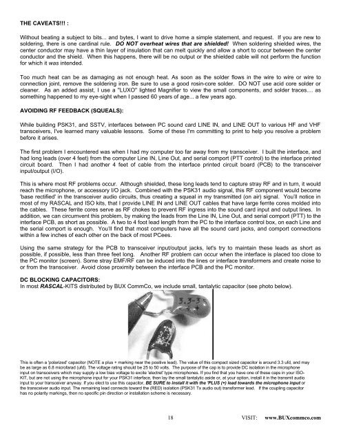
In most RASCAL-KITS distributed by BUX CommCo, we include small, tantalytic capacitor (see photo below).<br />
This is often a 'polarized' capacitor (NOTE a plus + marking near the positive lead). The value of this compact sized capacitor is around 3.3 ufd, and may<br />
be as large as 6.8 microfarad (ufd). The voltage rating should be 25 to 50 volts. The purpose of the cap is to provide DC isolation in the microphone<br />
input on transceivers which may supply a low bias voltage to excite 'electret' type microphones. If you find that you have one of these caps in your ISO-<br />
KIT, but are not using the microphone input for your <strong>PSK</strong>31 interface, then lay the small tantalytic aside or, at your option, install it in the transmit audio<br />
input to your transceiver anyway. If you elect to use this capacitor, BE SURE to install it with the 'PLUS (+) lead towards the microphone input or<br />
the transceiver audio input. The remaining lead connects toward the (RED) isolation (<strong>PSK</strong>31 Tx audio out) transformer lead. If the coupling capacitor<br />
has no polarity markings, then no specific pin direction or installation scheme is necessary.<br />
18<br />
VISIT: www.BUXcommco.com