You also want an ePaper? Increase the reach of your titles
YUMPU automatically turns print PDFs into web optimized ePapers that Google loves.
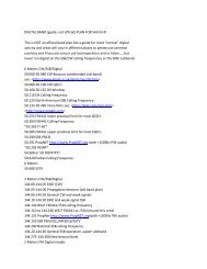
There's always that one final little 'knat-bite' that is the ''got'cha'' for many new HAMs who've never had the chance to<br />
work with integrated circuits. I've drawn an IC (shown above) similar to the 4N33 or 4N37 that are used in many of my<br />
RASCAL, <strong>PSK</strong>31 interfaces. NOTE, that pin 1 is identified by a small, almost obscure circle just above the pin (1) location.<br />
IF…. The dot is not on the IC, then use the small notch to help you identify pin one (1). Hold the opto-isolator (IC) so you<br />
are looking into the notch. Pin one (1) is the pin on the right side, nearest you. I hope my illustration will clarify pin<br />
identification of the 4N33 and 4N37 opto-coupler/opto-isolator/phototransistor.<br />
Red LED<br />
"Long Lead"<br />
For PTT using RTS line, use<br />
GREEN wire. For PTT using<br />
DTR, use RED wire.<br />
BARE WIRE from RS232 ground.<br />
** J1=3/8" stranded wire jumper.<br />
*** NOTE: When External Speaker is<br />
used for receive audio, T2 has "BLUE"<br />
winding covering. BLUE = 1K to 8 ohms.<br />
When low-level, or accessory jack audio<br />
is used, T2 has "RED" winding covering.<br />
"RED" = 600 to 600 ohms.<br />
"GREEN" Plug!<br />
"Shield"<br />
Sound Card<br />
"LINE IN" "TIP" (white wire)<br />
LED "Flat Side"<br />
"Short Lead"<br />
3<br />
NC<br />
P<br />
1<br />
2<br />
"B"<br />
***<br />
R1<br />
**<br />
J1<br />
"A"<br />
NC<br />
6<br />
"SLEEVE" TO "B"<br />
To EXT. SPKR.<br />
"TIP" TO "A"<br />
Receive Audio<br />
3.5mm External Speaker plug is used when T2 has<br />
BLUE covering. When MIC is used for Tx AF & PTT.<br />
NOTE: Some Yaesu transceivers us the "ring" of a<br />
3.5mm "stereo" plug for receive AF. Be sure to check<br />
the AF OUT connector on the RASCAL schematic diagram.<br />
T2<br />
5<br />
4<br />
20<br />
Dot or notch nearest edge of<br />
PC board, denotes pin 1 of<br />
optoisolator.<br />
R3 is only used in RASCAL 3 and RASCAL 20<br />
kits. The value of R3 is 2k (2000 ohms) Free end<br />
of R3 connects to junction of C1 and<br />
C1<br />
+<br />
_ transmit audio lead.<br />
C1= 0.33 to 1 uf capacitor<br />
(RASCAL MODELS R-3 and R-20, C1 = 10 uF)<br />
T1<br />
RED<br />
P<br />
_<br />
"TIP" (red wire) "WHITE" Plug!<br />
"Shield"<br />
Sound Card<br />
"LINE OUT"<br />
TOP VIEW (COMPONENT SIDE) OF PRINTED CIRCUIT BOARD. SOLDER TRACES "shown" ARE ON BOTTOM OF PC BOARD.<br />
R2<br />
N/C<br />
(POT)<br />
Transmit Audio level control.<br />
* *<br />
NOTICE !<br />
J1 MUST BE INSTALLED<br />
AS SHOWN.<br />
Connect J1 (jumper)<br />
from IC pin 4, to<br />
radio ground as shown.<br />
To Accessory Jack or MIC plug.<br />
Bare Wire (SHIELD/Radio Ground)<br />
Transmit Audio (WHITE)<br />
PTT + (RED)<br />
PTT - (BLACK,may be same as radio GND.)<br />
Receive Audio, (YELLOW or blue)<br />
VISIT: www.BUXcommco.com