Mismatch and synchronization: Influence of asymmetries in ... - CSIC
Mismatch and synchronization: Influence of asymmetries in ... - CSIC
Mismatch and synchronization: Influence of asymmetries in ... - CSIC

Create successful ePaper yourself
Turn your PDF publications into a flip-book with our unique Google optimized e-Paper software.
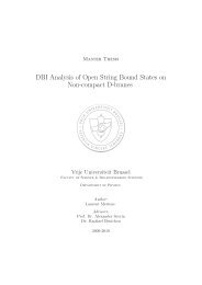
K. HICKE et al. PHYSICAL REVIEW E 83, 056211 (2011)For K = 0 or L = 0, the transversal <strong>and</strong> longitud<strong>in</strong>al(with<strong>in</strong> the <strong>synchronization</strong> manifold) stability properties <strong>of</strong>the modes are equal, <strong>and</strong> s<strong>in</strong>ce all modes, except for themaximum ga<strong>in</strong> mode, are longitud<strong>in</strong>ally unstable, zero-lag<strong>synchronization</strong> is determ<strong>in</strong>istically unstable too [22]. Thecorrelation is thus small (see Fig. 2).In the coherence collapse regime, which occurs for higherpump currents, the dynamics can be described as a chaoticit<strong>in</strong>erancy between modes <strong>and</strong> antimodes. Also <strong>in</strong> this case, thenumber <strong>of</strong> transversely stable modes decreases with <strong>in</strong>creas<strong>in</strong>gmismatch, lead<strong>in</strong>g to more de<strong>synchronization</strong> events. We alsonote that the number <strong>of</strong> stable modes decreases for <strong>in</strong>creas<strong>in</strong>gpump current if the ga<strong>in</strong> saturation effect is not accountedfor, i.e., μ = 0. The transverse stability <strong>of</strong> the modes is higher,tak<strong>in</strong>g <strong>in</strong>to account ga<strong>in</strong> saturation, which expla<strong>in</strong>s the broaderarea <strong>of</strong> high <strong>synchronization</strong> levels <strong>in</strong> Fig. 2. For a moredetailed discussion <strong>of</strong> the nonl<strong>in</strong>ear ga<strong>in</strong>, see Sec. V.The correlation between the two lasers at zero lag dependson the difference <strong>of</strong> self-coupl<strong>in</strong>g <strong>and</strong> cross coupl<strong>in</strong>g, but itdoes not depend on the sign <strong>of</strong> the mismatch, i.e, whether K>L or L>K. This can aga<strong>in</strong> be understood by look<strong>in</strong>g at theECMs’ transverse stability, which depends on the magnitude<strong>of</strong> L − K, but not on the sign.When <strong>in</strong>vestigat<strong>in</strong>g the correlation at nonzero lags <strong>and</strong>the stability <strong>of</strong> <strong>synchronization</strong> <strong>of</strong> the leader-laggard type,we get different results. Consider<strong>in</strong>g the peaks <strong>of</strong> the crosscorrelationfunction at shifts <strong>of</strong> multiples <strong>of</strong> the delay time,kτ, k ≠ 0 [Fig. 4(b)], we f<strong>in</strong>d that if L − K <strong>in</strong>creases (positivemismatch), all considered non-zero-lag peaks decrease <strong>in</strong> thesame way. The correspond<strong>in</strong>g peaks <strong>in</strong> the autocorrelation <strong>and</strong>thus the dynamics <strong>of</strong> the lasers do not change much with apositive mismatch [Fig. 4(a)].For a negative mismatch (K >L), the lasers evolvegradually from identical zero-lag <strong>synchronization</strong> to generalized<strong>synchronization</strong> <strong>of</strong> the leader-laggard type: the crosscorrelationpeak at one delay time <strong>and</strong> other odd numberedpeaks do not change much with the mismatch, but thecorrelation at zero lag <strong>and</strong> at even multiples <strong>of</strong> the delay vanish[Fig. 4(b)]. Also the autocorrelation is affected: the even peaksrema<strong>in</strong> <strong>and</strong> the odd peaks vanish [Fig. 4(a)]. Note that thesum <strong>of</strong> the autocorrelation <strong>and</strong> cross-correlation function issymmetric for positive <strong>and</strong> negative mismatch (not shown).III. DRIVE-RESPONSE CONFIGURATION: OPEN ANDCLOSED LOOPA coupl<strong>in</strong>g configuration that is frequently used for chaoscommunication purposes is a drive-response configuration[10,14,47,48]. The drive laser, or transmitter, is subject toits own delayed feedback; the respond<strong>in</strong>g laser, or receiver,receives a chaotic <strong>in</strong>put from the transmitter. In a so-calledclosed-loop configuration, which is depicted schematically <strong>in</strong>Fig. 5, the receiver is also a chaotic element subject to its ownfeedback. In the open-loop configuration, the receiver has noself-feedback <strong>and</strong> therefore exhibits a stable cont<strong>in</strong>uous waveoutput when decoupled from the transmitter. Both cases canbe modeled byX˙1 = f (X 1 ) + KCX 1 (t − τ), (9)X˙2 = f (X 2 ) + (1 − ɛ)KCX 1 (t − τ c ) + ɛKCX 2 (t − τ). (10)FIG. 4. (Color onl<strong>in</strong>e) Evolution <strong>of</strong> the peaks <strong>of</strong> the autocorrelation<strong>and</strong> cross-correlation function C(t), respectively, with themismatch L − K. Both correlations are calculated for the lasers’<strong>in</strong>tensities: (a) autocorrelation <strong>and</strong> (b) cross-correlation. Black thickl<strong>in</strong>e: cross-correlation at zero lag C(0). Blue circles: peak at one delaytime C(τ). Red diamonds: C(2τ). Green squares: C(3τ). Magentatriangles: C(4τ). Parameters: τ = 1000, μ = 0, p = 1, T = 200,β = 10 −5 .If ɛ = 0, we have an open-loop receiver, <strong>and</strong> if ɛ>0, theconfiguration is a closed loop.The dynamics <strong>in</strong> the <strong>synchronization</strong> manifold is the dynamics<strong>of</strong> the transmitter laser, S(t) = X 1 (t). Synchronizationwithout any time shift occurs only for τ c = τ. Ifτ>τ c ,the receiver laser’s dynamics anticipates the transmitter’sdynamics, <strong>and</strong> for τ
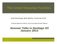
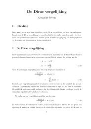
MISMATCH AND SYNCHRONIZATION: INFLUENCE OF ... PHYSICAL REVIEW E 83, 056211 (2011)<strong>of</strong> this system. Instead a time-shifted synchronized solutionX 1 (t) = X 2 (t − τ) is possible [31]. To analyze the stability<strong>of</strong> this time-shifted identically synchronized solution, wedef<strong>in</strong>e the symmetric variable as S(t) = 1 2 [X 1(t + τ) +X 2 (t)] <strong>and</strong> the antisymmetric variable as A(t) = 1 2 [X 1(t +τ) − X 2 (t)]. The temporal evolution <strong>of</strong> these two variablesis then given byFIG. 6. Scheme <strong>of</strong> a bidirectional coupl<strong>in</strong>g setup with a delaymismatch <strong>of</strong> the self-feedback. The distances are given <strong>in</strong> time for aone-way trip. Both self-feedback strengths have the value L <strong>and</strong> thecoupl<strong>in</strong>g strengths both equal K.When l<strong>in</strong>eariz<strong>in</strong>g around A(t) = 0, we f<strong>in</strong>d that the l<strong>in</strong>earstability <strong>of</strong> the zero-lag synchronized solution <strong>in</strong> an openloopreceiver (ɛ = 0) is the same as the setup <strong>of</strong> two laserscoupled through a semitransparent mirror, without self- <strong>and</strong>cross-coupl<strong>in</strong>g mismatch (L = K). In contrast, <strong>in</strong> a closedloopreceiver, the stability <strong>of</strong> the <strong>synchronization</strong> manifoldis the same as <strong>in</strong> a mirror setup with a mismatch betweenself-coupl<strong>in</strong>g <strong>and</strong> cross-coupl<strong>in</strong>g.In chaotic communication, the open-loop configuration istraditionally preferred over the closed-loop scheme becauseit is more robust aga<strong>in</strong>st parameter mismatches <strong>and</strong> mucheasier to implement. In addition, the re<strong>synchronization</strong> time<strong>in</strong> the case <strong>of</strong> a sudden <strong>in</strong>terruption <strong>of</strong> the connection ismuch shorter (see Ref. [13] <strong>and</strong> references there<strong>in</strong>). It wasshown [37], however, that if the feedback delays are identical,the <strong>synchronization</strong> quality for the closed-loop rather thanfor the open-loop scheme is much higher. Also Ref. [49]showed that the performance <strong>of</strong> closed-loop receivers are lesssensible to detun<strong>in</strong>g between the emitter <strong>and</strong> receiver. Furthermore,several methods consider<strong>in</strong>g chaotic communicationshave been proposed that take advantage <strong>of</strong> specific properties<strong>of</strong> the closed-loop configuration [13,50].Ṡ = 1 2[f (S + A) + f (S − A)]+ 1 2 (L + K)C[S(t − τ 1) + S(t − τ 2 )]+ 1 2 (L + K)C[A(t − τ 1) − A(t − τ 2 )], (15)Ȧ = 1 [f (S + A) − f (S − A)]2+ 1 2 (L − K)C[S(t − τ 1) − S(t − τ 2 )]+ 1 2 (L − K)C[A(t − τ 1) + A(t − τ 2 )]. (16)It is clear that a (time-shifted) synchronized solution [A(t) =0] only exists if the self-coupl<strong>in</strong>g <strong>and</strong> cross-coupl<strong>in</strong>g are equal(L = K). This is <strong>in</strong> contrast to the case without delay mismatch(see Sec. II), where for any values <strong>of</strong> K <strong>and</strong> L, a synchronizedsolution exists, although it may be unstable. Thus for the casewith delay mismatch, we expect a strong dependence <strong>of</strong> the<strong>synchronization</strong> quality on the coupl<strong>in</strong>g mismatch L − K.For K = L, the synchronized solution corresponds to onelaser subject to two different feedbacks with the same strength12 (K + L) = K <strong>and</strong> respective delays τ 1 <strong>and</strong> τ 2 . A l<strong>in</strong>earstability analysis <strong>of</strong> Eq. (16), orthogonal to the <strong>synchronization</strong>manifold around A(t) = 0, then leads toδA(t) ˙ = Df (S)δA. (17)IV. RELAY CONFIGURATION WITH DELAY MISMATCHA. Synchronization propertiesWe come back to the case <strong>of</strong> bidirectionally coupled laserswith self-feedback. As discussed above, this coupl<strong>in</strong>g schemecan be realized experimentally with a semitransparent mirrorbetween the lasers. We now assume that the mirror is no longerpositioned <strong>in</strong> the perfect middle between the two lasers. Thelasers are hence subject to a different feedback delay τ 1,2 =τ ± τ, but they still experience the same coupl<strong>in</strong>g delayτ = 1 2 (τ 1 + τ 2 ), s<strong>in</strong>ce the distance between the lasers does notchange. A schematic representation <strong>of</strong> the setup is shown <strong>in</strong>Fig. 6.We can then model this system via the equationsX˙1 = f (X 1 ) + 1 2 LCX 1[t − (τ + τ)]+ 1 2 KCX 2(t − τ), (13)X˙2 = f (X 2 ) + 1 2 LCX 2[t − (τ − τ)]+ 1 2 KCX 1(t − τ) , (14)where we consider, without loss <strong>of</strong> generality, τ 0.The first laser then has a larger self-feedback delay(τ 1 = τ + τ) than the second laser (τ 2 = τ − τ). Zerolag<strong>synchronization</strong> X 1 (t) = X 2 (t) is no longer a solutionFIG. 7. (Color onl<strong>in</strong>e) Dynamics <strong>and</strong> correlation <strong>of</strong> two delaycoupledlasers with a delay mismatch <strong>of</strong> τ = 100 <strong>in</strong> the coherencecollapse regime. Upper panel: time series <strong>of</strong> laser output <strong>in</strong>tensitiesI 1 (t) [green (dark gray) l<strong>in</strong>e] <strong>and</strong> I 2 (t) (black l<strong>in</strong>e). The time tracesexhibit a time lag <strong>of</strong> τ. For demonstration purposes, the noisewas disregarded <strong>in</strong> this simulation. Lower panel: cross-correlationfunction <strong>of</strong> laser <strong>in</strong>tensities. The time shift <strong>of</strong> the maximumcorrelation peak equals the delay mismatch: t =−τ. Simulatedwith noise β = 10 −5 . Parameters for both simulations are τ = 2000,α = 4.0, p = 1.0, μ = 0.26, T = 200; all coupl<strong>in</strong>g strengths wereidentical L = K = 0.1.056211-5
K. HICKE et al. PHYSICAL REVIEW E 83, 056211 (2011)Compar<strong>in</strong>g the stability <strong>of</strong> the <strong>synchronization</strong> manifoldwithout delay mismatch [Eq. (8)] for L = K <strong>and</strong> with delaymismatch [Eq. (17)], we see that the variational equationsare identical, <strong>and</strong> thus similar ECMs [i.e., solutions S(t) withsimilar frequency <strong>and</strong> carrier density] <strong>of</strong> both systems willhave comparable stability properties. Thus we can suspect thatan asymmetrically placed mirror does not have a large effecton the <strong>synchronization</strong> properties <strong>of</strong> the system, provided thatL = K. When simulat<strong>in</strong>g the system numerically, we <strong>in</strong>deedf<strong>in</strong>d identical <strong>synchronization</strong> <strong>of</strong> the two semiconductor lasers,with a time lag correspond<strong>in</strong>g to the difference <strong>in</strong> propagationtime between the lasers <strong>and</strong> the mirror, as shown <strong>in</strong> Fig. 7(upper panel). Also, <strong>in</strong> the cross-correlation function, the ma<strong>in</strong>correlation peak is shifted by τ (see Fig. 7, lower panel) asexpected.How does the peak height, i.e., the lag correlation, dependon the delay mismatch? In Fig. 8, the upper red curve depictsthe height <strong>of</strong> the correlation peak as a function <strong>of</strong> τ. Formost <strong>of</strong> the allowed range 0 τ τ, the correlation peakis large <strong>and</strong> the <strong>synchronization</strong> quality is high. The position <strong>of</strong>the mirror does not have a large effect on the <strong>synchronization</strong>level.If we consider both a mismatch <strong>in</strong> the transmission <strong>and</strong>reflection <strong>of</strong> the mirror <strong>and</strong> a delay mismatch (Fig. 9), we f<strong>in</strong>dthat the area around the diagonal L = K synchronizes well,but the correlation breaks down even for a small mismatch <strong>in</strong>the coupl<strong>in</strong>g, <strong>in</strong> contrast to the case τ = 0 (Fig. 2). In otherwords, if the mirror is asymmetrically placed, the system ismuch more sensitive to a coupl<strong>in</strong>g mismatch, as was impliedby Eq. (16) <strong>and</strong> discussed above.B. Dynamical regimesAlthough the delay mismatch does not affect the quality <strong>of</strong>the (lag) <strong>synchronization</strong> <strong>of</strong> the coupled lasers, it does havea significant effect on the dynamics <strong>in</strong> the <strong>synchronization</strong>FIG. 8. (Color onl<strong>in</strong>e) Cross-correlation C(t)atshiftt = τ<strong>of</strong> the output <strong>in</strong>tensities <strong>of</strong> both lasers (upper red l<strong>in</strong>e), <strong>and</strong> the peakat t = 2τ <strong>of</strong> the autocorrelation function <strong>of</strong> one laser (lower bluel<strong>in</strong>e), versus the delay mismatch parameter τ. The peaks co<strong>in</strong>cide:higher regularity (peak <strong>in</strong> the autocorrelation) means stronger crosscorrelation(peak <strong>in</strong> the correlation coefficient). Parameters areτ = 1000, α = 4.0, p = 1.0, μ = 0.26, T = 200, L = K = 0.1,β = 10 −5 .FIG. 9. (Color onl<strong>in</strong>e) Cross-correlation C(t)atshiftt = τ<strong>of</strong> the field <strong>in</strong>tensities <strong>of</strong> two coupled lasers <strong>in</strong> a configuration,accord<strong>in</strong>g to Fig. 6, vsL <strong>and</strong> K. In comparison with Fig. 2, thesystem is more sensitive to a mismatch <strong>of</strong> the coupl<strong>in</strong>g L − K. τ =20. Other parameters are τ = 1000, μ = 0.26, α = 4.0, p = 1.0,T = 200, β = 10 −5 .manifold itself. When synchronized (with a time lag), thetwo subsystems behave like one laser, subject to two equallystrong feedbacks with different delays. This <strong>in</strong>troduction <strong>of</strong> asecond delay changes the alignment <strong>of</strong> the ECMs. The ECMansatz E(t) = Ae iωt , n(t) = n leads, after elim<strong>in</strong>at<strong>in</strong>g A, toa transcendental frequency equation <strong>and</strong> an equation for thecarrier density,ω =−2K √ 1 + α 2 s<strong>in</strong>(arctan α − ωτ) cos(ωτ), (18)pμ − 2K[cos(ωτ) cos(ωτ)]n = . (19)1 + μThe modes <strong>of</strong> this system are located <strong>in</strong>side the area <strong>of</strong> theellipse that is the solution space for a laser subject to only onefeedback with a strength <strong>of</strong> 2K. We note that if r τ = τ 1 /τ 2 ∈Q, the modes lie on a closed curve, <strong>and</strong> irrational ratios r τresult <strong>in</strong> a more complicated mode spectrum. Tronciu et al.[12], who <strong>in</strong>vestigated the correspond<strong>in</strong>g case <strong>of</strong> lasers subjectto feedback from an <strong>in</strong>tegrated double cavity, found chaoticbehavior for lower feedback strengths than needed for thecase <strong>of</strong> s<strong>in</strong>gle feedback. The more complex mode alignmentwas postulated as a cause for a more complex dynamics. Thecomplex alignment <strong>of</strong> the modes for τ ≠ 0 only dependson the delay mismatch, not on the delay time τ. S<strong>in</strong>ce thedynamics is organized by the mode spectrum, it is strongly<strong>in</strong>fluenced by the changes <strong>in</strong> the mode structure.For a small mismatch, the double delay setup exhibits afilter<strong>in</strong>g effect similar to a Michelson <strong>in</strong>terferometer [51],s<strong>in</strong>ce the frequencies for which ωτ ≈ (2m + 1) π 2 , m ∈ Zare filtered out. This effect results <strong>in</strong> the formation <strong>of</strong> “modeisl<strong>and</strong>s.” Close to simple rational ratios <strong>of</strong> r τ , we observesimilar phenomena.In Fig. 10, exemplary phase-space portraits are shown fordifferent values <strong>of</strong> the delay mismatch τ for a fixed me<strong>and</strong>elay time τ = 1000. The areas where the transversely stablemodes are located are similar for all delay mismatches τ.Dueto the different mode spectrum, the dynamics is significantlyaltered compared to the case τ = 0.A semiconductor laser subject to two self-feedbacks withdifferent strength <strong>and</strong> delay has been studied by Liu <strong>and</strong>Ohtsubo [52], who showed that one can stabilize the dynamicsto fixed po<strong>in</strong>ts or limit cycles. This effect was found strongestfor unequal feedback strengths. Rogister et al. [53] showed056211-6
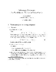
MISMATCH AND SYNCHRONIZATION: INFLUENCE OF ... PHYSICAL REVIEW E 83, 056211 (2011)FIG. 11. (Color onl<strong>in</strong>e) Cross-correlation coefficient (upper redl<strong>in</strong>es), <strong>and</strong> auto-correlation at t = 2τ (lower blue l<strong>in</strong>es), vs the delaymismatch parameter τ for rational ratios <strong>of</strong> the delay times τ 1 <strong>and</strong>τ 2 . Magnifications <strong>of</strong> plot <strong>in</strong> Fig. 8. (a)r τ = τ 1τ 2= 1/1, (b) r τ = 2/1,(c) r τ = 3/1, (d) τ ≈ τ. Parameters as <strong>in</strong> Fig. 8.FIG. 10. (Color onl<strong>in</strong>e) Dynamics <strong>of</strong> the symmetrized solution(E S ,n S )<strong>in</strong>the(ω,n S ) phase space for different values <strong>of</strong> the delaymismatch parameter τ after t = 5 × 10 4 . For a def<strong>in</strong>ition <strong>of</strong> ω<strong>and</strong> n S , see Fig. 3. The ECMs for a laser subject to two delayedfeedbacks with different delay times are aligned <strong>in</strong>side the area <strong>of</strong>the mode ellipse for the case where the delays are equal. Green (lightgray) circles are transversely stable modes; red (black) triangles aretransversely unstable modes <strong>and</strong> antimodes. The it<strong>in</strong>eracy is drawn<strong>in</strong> blue (dark gray) <strong>and</strong> marked with an arrow if stabilized. The me<strong>and</strong>elay time τ is fixed at τ = 1000. The other parameters are α = 4.0,p = 1.0 (except lower right), μ = 0.26, K = 0.1. Note that the lowerright plot has a different y scale than the others.that chaotic dynamics <strong>and</strong> LFF can be suppressed for a s<strong>in</strong>glelaser, subject to two different feedbacks, by suppress<strong>in</strong>g theantimodes that are responsible for power dropouts [44]. Thisstabilization <strong>of</strong> the dynamics occurs ma<strong>in</strong>ly for a short secondfeedback. Increas<strong>in</strong>g the second feedback strength from a lowlevel to the magnitude <strong>of</strong> the first one results <strong>in</strong> a bifurcationcascade <strong>in</strong> the laser, lead<strong>in</strong>g to several dynamical regimes<strong>in</strong>clud<strong>in</strong>g stable behavior.In a configuration <strong>of</strong> two lasers coupled via a semitransparentmirror, we observe similar changes <strong>in</strong> the dynamics.We calculated the secondary peak <strong>of</strong> the autocorrelation <strong>of</strong>each laser at t = 2τ to <strong>in</strong>vestigate the regularity <strong>of</strong> thetime series. The height <strong>of</strong> the autocorrelation peak exhibitssignificant extrema (see Fig. 8, lower blue l<strong>in</strong>e) for certa<strong>in</strong>delay mismatches. In particular, we f<strong>in</strong>d dips <strong>and</strong> peaks <strong>in</strong>the vic<strong>in</strong>ity <strong>of</strong> simple rational values <strong>of</strong> r τ <strong>and</strong> also aroundr τ = 1(τ ≈ 0) <strong>and</strong> r τ →∞ (τ ≈ τ). At these po<strong>in</strong>ts,naturally the cross correlation also exhibits dips <strong>and</strong> peaks(see Fig. 11, upper red l<strong>in</strong>e). These are primarily caused bya change <strong>in</strong> the underly<strong>in</strong>g dynamical state <strong>of</strong> the system<strong>and</strong> not by a change <strong>of</strong> the <strong>synchronization</strong> quality. Loweredcross-correlation values have been tested to be caused by asmall signal-to-noise ratio when the dynamics is stabilized to afixed po<strong>in</strong>t. Delay mismatches that lead to a stabilization <strong>of</strong> thedynamics to a limit cycle result <strong>in</strong> a peak <strong>in</strong> the autocorrelation<strong>and</strong> cross correlation due to the coherent behavior.To further <strong>in</strong>vestigate the changes <strong>in</strong> the laser dynamics forvary<strong>in</strong>g delay mismatch, we compute a bifurcation diagram. Inthe diagram, which is shown <strong>in</strong> Fig. 12, several <strong>in</strong>tensity maxima<strong>and</strong> m<strong>in</strong>ima extracted from a time trace <strong>of</strong> each laser areplotted versus the delay mismatch τ. The dynamics changessignificantly for vary<strong>in</strong>g delay mismatch, when the delays areclose to a simple ratio, e.g., r τ = 1/1, 2/1, 3/2, .... EspeciallyFIG. 12. (Color onl<strong>in</strong>e) Bifurcation diagram <strong>of</strong> the <strong>in</strong>tensityextrema <strong>of</strong> the two lasers vs the delay mismatch parameter τ. Uppergreen po<strong>in</strong>ts are maxima; lower red po<strong>in</strong>ts are m<strong>in</strong>ima. Vary<strong>in</strong>g thedelay mismatch results <strong>in</strong> radical changes <strong>in</strong> the dynamics, which isevident, e.g., by the changes <strong>in</strong> the variance <strong>of</strong> the <strong>in</strong>tensity outputs.Magnifications are shown for a small delay mismatch τ < 15 (lowerleft), a delay times ratio <strong>of</strong> r τ ≈ 2/1 (lower middle), <strong>and</strong> one veryshort delay τ 1 ≫ τ 2 (lower right). Other parameters are τ = 1000,α = 4.0, μ = 0.26, p = 1.0, T = 200, β = 10 −5 .056211-7
K. HICKE et al. PHYSICAL REVIEW E 83, 056211 (2011)for τ ≈ 0 (almost equal delay times) <strong>and</strong> τ τ (when onedelay is very short), the variance <strong>of</strong> the <strong>in</strong>tensity decreasesdramatically. Also we notice a significant drop <strong>in</strong> varianceat around τ = 333. This delay mismatch corresponds to arational ratio <strong>of</strong> r τ = 2/1 <strong>of</strong> the delay times. At these values <strong>of</strong>the delay mismatch, the dynamics settles on a stable periodicorbit.The narrowest distances between maxima <strong>and</strong> m<strong>in</strong>ima<strong>in</strong>dicate a stable s<strong>in</strong>gle mode emission. For these cases,the autocorrelation <strong>and</strong> cross correlation show large peaks,however, this does not correspond to chaos <strong>synchronization</strong>.The stabilization <strong>of</strong> the dynamics for several delay mismatchesis illustrated <strong>in</strong> Fig. 10, which shows the laserdynamics projected onto the (ω,n) phase space. Close tothe rational ratio r τ = 2/1 (τ ≈ 333 <strong>in</strong> this case), we seeoscillations <strong>of</strong> the dynamics around a s<strong>in</strong>gle mode [Figs. 10(e)<strong>and</strong> 10(g)]. The values for the delay mismatch correspondto those <strong>of</strong> the local peaks <strong>in</strong> the autocorrelation function <strong>in</strong>Fig. 11(b). At the exact rational ratio τ = 333, however,no such stabilization is observed [Fig. 10(f)]. For small delaymismatches [Figs. 10(b) <strong>and</strong> 10(c)], the dynamics exhibitsrobust <strong>and</strong> fast stabilization to a s<strong>in</strong>gle mode. This stabiliz<strong>in</strong>gproperty for a slightly misaligned semitransparent mirror isrobust aga<strong>in</strong>st the variation <strong>of</strong> several parameters, such asabsolute delay time, coupl<strong>in</strong>g strength, <strong>and</strong> noise magnitude.Simulations over broad ranges <strong>of</strong> these respective parametersresulted <strong>in</strong> stabilization <strong>of</strong> the dynamics. With a strong enoughnonl<strong>in</strong>ear ga<strong>in</strong> saturation, the dynamics <strong>and</strong> mode spectrumcan be adjusted <strong>in</strong> such a way that high-level <strong>synchronization</strong><strong>and</strong> the stabilization <strong>of</strong> the dynamics described above occur.(For more details on the effect <strong>of</strong> ga<strong>in</strong> saturation, see the nextsection).To expla<strong>in</strong> the stabilization at small delay mismatches <strong>and</strong> atdelay mismatches close to simple delay ratios r τ , we speculateas follows. Consider a laser subject to a delayed feedback fromtwo feedback loops with delays τ + τ <strong>and</strong> τ − τ. Let usassume that at τ = 0, the laser operates <strong>in</strong> a chaotic regime,where the chaos is <strong>in</strong>duced by the feedback. Although thelaser output is chaotic, there is, on average, a short-term phasecorrelation <strong>of</strong> the electric field, i.e., the peak at the orig<strong>in</strong> <strong>of</strong>the autocorrelation function <strong>of</strong> the field is surrounded by localm<strong>in</strong>ima <strong>and</strong> maxima. The first local m<strong>in</strong>imum <strong>and</strong> maximumis usually very pronounced because <strong>of</strong> a characteristic smalloscillation period present <strong>in</strong> the chaotic signal. If we nowchange τ such that it corresponds to the first m<strong>in</strong>imum, then,on average, the arriv<strong>in</strong>g feedback signals will destructively<strong>in</strong>terfere, thus dim<strong>in</strong>ish<strong>in</strong>g the amplitude <strong>and</strong> the fluctuations<strong>of</strong> the feedback signal, which may lead to more regularbehavior <strong>of</strong> the laser. The above usually also holds for thechoice <strong>of</strong> a small rational ratio <strong>of</strong> the delay times, i.e., τ ∈ Q.τOf course, shift<strong>in</strong>g τ will result <strong>in</strong> a different autocorrelationfunction, <strong>in</strong> particular <strong>in</strong> the case <strong>of</strong> successful stabilization.However, it can still be assumed that this k<strong>in</strong>d <strong>of</strong> destructive<strong>in</strong>terference mechanism can, <strong>in</strong> a self-consistent way, result <strong>in</strong>stabilization <strong>of</strong> the dynamics.V. NONLINEAR GAIN SATURATIONFor our analysis, we have used a Lang-Kobayashi-typemodel with a nonl<strong>in</strong>ear ga<strong>in</strong> function G(E j ,n). A nonl<strong>in</strong>earFIG. 13. (Color onl<strong>in</strong>e) Effect <strong>of</strong> the nonl<strong>in</strong>ear ga<strong>in</strong> saturationon the alignment <strong>and</strong> transverse stability <strong>of</strong> the external cavitymodes <strong>in</strong> the (ω,n S ) phase space; p = 1.0. The larger the pumpcurrent value is, the more pronounced is the effect. Red (black)circles: transversely unstable antimodes. Green (light gray) circles:transversely stable modes. The dynamics is shown <strong>in</strong> blue (dark gray).The other parameters are τ = 1000, τ = 0, α = 4.0, T = 200,K = 0.1, β = 10 −5 . Inset: bifurcation diagram with vary<strong>in</strong>g μ. Uppergreen po<strong>in</strong>ts: maxima <strong>of</strong> <strong>in</strong>tensities; lower red po<strong>in</strong>ts: m<strong>in</strong>ima <strong>of</strong><strong>in</strong>tensities.ga<strong>in</strong>, which saturates for high <strong>in</strong>tensities, is <strong>of</strong>ten used toaccount for nonl<strong>in</strong>ear deviations <strong>of</strong> the characteristics <strong>of</strong> theoptical power versus <strong>in</strong>jection current far above the threshold.The nonl<strong>in</strong>ear ga<strong>in</strong> saturation is a phenomenologically<strong>in</strong>troduced term that is motivated by nonl<strong>in</strong>ear effects <strong>in</strong> thesemiconductor ga<strong>in</strong> medium, like spectral hole burn<strong>in</strong>g <strong>and</strong>carrier heat<strong>in</strong>g. A l<strong>in</strong>ear ga<strong>in</strong> theory cannot account for thosephenomena.With <strong>in</strong>creas<strong>in</strong>g pump current, the nonl<strong>in</strong>ear ga<strong>in</strong> saturationbecomes more relevant <strong>and</strong> has an <strong>in</strong>creas<strong>in</strong>g effect on thedynamics <strong>of</strong> the lasers, e.g., on the precise position <strong>in</strong> phasespace [see Eq. (19)] <strong>and</strong> the transverse stability <strong>of</strong> the externalcavity modes.When operat<strong>in</strong>g <strong>in</strong> the LFF regime, the effect <strong>of</strong> nonl<strong>in</strong>earga<strong>in</strong> saturation can <strong>of</strong>ten be neglected. In the coherencecollapse (CC) regime, however, the high power means that ga<strong>in</strong>saturation plays an <strong>in</strong>creas<strong>in</strong>g role. This effect is illustrated <strong>in</strong>Fig. 13. Increas<strong>in</strong>g the nonl<strong>in</strong>ear ga<strong>in</strong> saturation μ leads toa smaller maximum field <strong>in</strong>tensity <strong>and</strong> a decreased variance<strong>of</strong> the <strong>in</strong>tensity <strong>and</strong> carrier density. The <strong>in</strong>set <strong>in</strong> Fig. 13shows this effect via a distribution <strong>of</strong> <strong>in</strong>tensity extrema forvary<strong>in</strong>g μ.In the coupled laser system, the number <strong>of</strong> transverselystable modes <strong>in</strong>creases with <strong>in</strong>creas<strong>in</strong>g μ <strong>and</strong> the modes areshifted so that critical events with antimodes <strong>and</strong> de<strong>synchronization</strong>are less likely—the synchronized state is more stable.However, the dynamics is also less complex.With a model that omits the nonl<strong>in</strong>ear ga<strong>in</strong> (μ = 0), allmodes <strong>in</strong> the vic<strong>in</strong>ity <strong>of</strong> the m<strong>in</strong>imum ga<strong>in</strong> mode (aroundω = 0) are transversely unstable above a critical pumpcurrent. Without ga<strong>in</strong> saturation, the lasers experience many056211-8
MISMATCH AND SYNCHRONIZATION: INFLUENCE OF ... PHYSICAL REVIEW E 83, 056211 (2011)FIG. 14. (Color onl<strong>in</strong>e) Cross-correlation <strong>of</strong> the field <strong>in</strong>tensitiesvs K <strong>and</strong> L with <strong>and</strong> without delay mismatch. (a) Symmetric delays:τ = 0, zero-lag <strong>synchronization</strong>; (b) with delay mismatch τ =20, cross-correlation at t = τ. The nonl<strong>in</strong>ear ga<strong>in</strong> saturation isignored for these simulations. Parameters: μ = 0, p = 1.0, α = 4.0,T = 200, τ = 1000, <strong>and</strong> noise β = 10 −5 .de<strong>synchronization</strong> events or do not synchronize at all. TheL − K plots <strong>in</strong> Fig. 14 show therefore significantly smaller areas<strong>of</strong> high <strong>synchronization</strong> for μ = 0 than the correspond<strong>in</strong>gplots for μ = 0.26 (Figs. 2 <strong>and</strong> 9).VI. CONCLUSIONSWe have numerically <strong>and</strong> analytically <strong>in</strong>vestigated thedynamical <strong>and</strong> <strong>synchronization</strong> properties <strong>of</strong> a system <strong>of</strong>two delay-coupled semiconductor lasers <strong>in</strong> different coupl<strong>in</strong>gschemes. Us<strong>in</strong>g a model for a setup <strong>of</strong> two lasers coupledvia a semitransparent mirror, we have studied the <strong>in</strong>fluence<strong>of</strong> a mismatch between the transmission <strong>and</strong> reflection <strong>of</strong>the mirror, i.e., a mismatch between coupl<strong>in</strong>g <strong>and</strong> feedbackstrength, as well as a delay mismatch correspond<strong>in</strong>g to amisalignment <strong>of</strong> the mirror from the middle.We showed that a coupl<strong>in</strong>g mismatch deteriorates thestability <strong>of</strong> the synchronized solution, but does not change thesynchronized dynamics. In both the LFF regime <strong>and</strong> the CCregime, a larger mismatch results <strong>in</strong> longer bubbl<strong>in</strong>g events,s<strong>in</strong>ce less modes are transversely stable. However, we stillobserve high-level <strong>synchronization</strong> if the mismatch |L − K|rema<strong>in</strong>s small. The cross-correlation (at zero lag) <strong>of</strong> the twolasers does not depend on the sign <strong>of</strong> the mismatch betweencoupl<strong>in</strong>g <strong>and</strong> feedback L − K, but only on the absolute value.The <strong>in</strong>clusion <strong>of</strong> a saturable nonl<strong>in</strong>ear ga<strong>in</strong> leads not only toa reduction <strong>of</strong> complexity <strong>in</strong> the time series but also to a broaderdoma<strong>in</strong> <strong>of</strong> high <strong>synchronization</strong> quality, s<strong>in</strong>ce it <strong>in</strong>creases thetransverse stability <strong>of</strong> the ECMs.Our analysis has shown that the <strong>synchronization</strong> properties<strong>of</strong> a configuration with a semitransparent mirror are the sameas those <strong>of</strong> a drive-response configuration, at least on thelevel <strong>of</strong> the ECMs. An open-loop configuration synchronizesbest; the transverse stability <strong>of</strong> the modes is the same as<strong>in</strong> a configuration without coupl<strong>in</strong>g mismatch. Add<strong>in</strong>gself-feedback to the receiver has the same effect on stabilityas <strong>in</strong>troduc<strong>in</strong>g a coupl<strong>in</strong>g mismatch <strong>in</strong> the relay setup.If there is a delay mismatch, we found that the laserscan synchronize with a nonzero lag. The time traces thenexhibit a relative time shift proportional to the misalignment<strong>of</strong> the mirror. The stability <strong>of</strong> the time-shifted identical<strong>synchronization</strong> <strong>of</strong> the lasers is not much affected by the value<strong>of</strong> the delay mismatch. The dynamics, however, undergoesdrastic changes for vary<strong>in</strong>g τ, as the alignment <strong>of</strong> theexternal cavity modes is altered compared to symmetricdelays.Especially for very small mismatch, for rational ratios<strong>of</strong> the respective delay times, <strong>and</strong> if the second delay isvery short compared to the first one, the chaotic dynamicscan be suppressed <strong>and</strong> stabilized toward either s<strong>in</strong>gle modeoutput or periodic behavior. These qualitative features do notdepend on the delay time, but merely on the delay mismatch<strong>and</strong> relative ratios <strong>of</strong> delay times. They were found robust forbroad ranges <strong>of</strong> the coupl<strong>in</strong>g strengths (i.e., the transmission<strong>and</strong> reflection <strong>of</strong> the relay mirror) <strong>and</strong> even for high noiselevels. We conjecture that they are caused by destructive<strong>in</strong>terference.We also found that a delay mismatch makes the systemmuch more sensitive to a coupl<strong>in</strong>g mismatch. The correlationbetween the two laser outputs decreases much more rapidlywith <strong>in</strong>creas<strong>in</strong>g coupl<strong>in</strong>g mismatch than for the case <strong>of</strong>symmetric delays.Our results are <strong>of</strong> high practical value for future(experimental) <strong>in</strong>vestigations consider<strong>in</strong>g delay-coupledlasers. The ability to target specific stability regions viamismatch adjustments can, for example, be helpful for chaoscommunication systems or r<strong>and</strong>om number generation. In addition,due to the broad <strong>in</strong>terest <strong>in</strong> <strong>synchronization</strong> phenomenathroughout the scientific community, our results concern notonly the immediate applications to chaotic communication,but may also be relevant to scientists <strong>in</strong> related fields suchas computational neuroscience, eng<strong>in</strong>eer<strong>in</strong>g, <strong>and</strong> biology.The presented analytical results can be transferred to otherdelay-coupled systems with correspond<strong>in</strong>g network topology<strong>and</strong> therefore could f<strong>in</strong>d applications, e.g., <strong>in</strong> electro-optic orneuronal systems.ACKNOWLEDGMENTSO.D. acknowledges the Research Foundation Fl<strong>and</strong>ers(FWO-Vla<strong>and</strong>eren) for support. This research was partiallysupported by MICINN (Spa<strong>in</strong>) under project DeCoDicA(Project No. TEC2009-14101), by DFG (Germany) <strong>in</strong> theframework <strong>of</strong> SFB 910, by the Interuniversity AttractionPoles program <strong>of</strong> the Belgian Science Policy Office, underGrant No. IAP VI-10 (photonics@be), <strong>and</strong> by the projectPHOCUS. The project PHOCUS, <strong>in</strong> turn, acknowledges thef<strong>in</strong>ancial support <strong>of</strong> the Future <strong>and</strong> Emerg<strong>in</strong>g Technologies(FET) program with<strong>in</strong> the Seventh Framework Programmefor Research <strong>of</strong> the European Commission, under FET-OpenGrant No. 240763.APPENDIX : STABILITY CALCULATION FOR CAVITYMODESAn external cavity mode (ECM) <strong>of</strong> the Lang-Kobayashiequations is a steady-state solution <strong>of</strong> the form E j = Ae iωt<strong>and</strong> n j = n. To calculate its (transverse) stability, we make thetransformation E j → Ee −iωt such that the ECM becomes asteady state, <strong>and</strong> split the electric field <strong>in</strong>to a real <strong>and</strong> imag<strong>in</strong>arypart E = A = x + iy. With this, we calculate the JacobianDf (S) with trajectory S correspond<strong>in</strong>g to the transformedECM solution. We then determ<strong>in</strong>e the eigenvalues <strong>of</strong> the056211-9
K. HICKE et al. PHYSICAL REVIEW E 83, 056211 (2011)l<strong>in</strong>earized right-h<strong>and</strong> side <strong>of</strong> Eq. (8),⎡⎛( ) ( )12 G − 1 − 2x2 ∂G∂I − λ ω−α2 G − 1 − 2 y 2 ∂G 1∂I 2⎢⎜( ) ( )det ⎣⎝−ω + α 2 G − 1 − 2 y 2 ∂G 1∂I 2 G − 1 − 2x2 ∂G∂I − λ12( )− 2xT G + I∂G− 2y ( )∂IT G + I∂G− 1 ∂IT∂G∂n∂G∂n⎞⎤⎛ ⎞(x − αy)1 0 0⎟⎥(αx + y) ⎠⎦ − (L − K)e −λτ ⎜ ⎟⎝0 1 0⎠ = 0, (A1))− λ 0 0 0(1 + I∂G∂nwhere I represents the <strong>in</strong>tensity <strong>of</strong> the laser, I =|A| 2 = x 2 + y 2 .If all <strong>of</strong> the result<strong>in</strong>g eigenvalues have negative real parts, it <strong>in</strong>dicates that the ECM is transversely stable: the magnitude <strong>of</strong>the small perturbation δ(t) <strong>in</strong>Eq.(8) decreases over time. However, if at least one eigenvalue has a positive real part, it meansthe ECM <strong>in</strong> question is transversely unstable.[1] A. S. Pikovsky, M. G. Rosenblum, <strong>and</strong> J. Kurths, Synchronization,A Universal Concept <strong>in</strong> Nonl<strong>in</strong>ear Sciences (CambridgeUniversity Press, Cambridge, 2001).[2] S. Boccaletti, J. Kurths, G. Osipov, D. L. Valladares, <strong>and</strong> C. S.Zhou, Phys. Rep. 366, 1 (2002).[3] H<strong>and</strong>book <strong>of</strong> Chaos Control, editedbyE.Schöll <strong>and</strong> H. G.Schuster (Wiley-VCH, We<strong>in</strong>heim, 2008).[4] W. S<strong>in</strong>ger, Neuron 24, 49 (1999).[5] W. S<strong>in</strong>ger, Nature (London) 397, 391 (1999).[6] L. M. Pecora <strong>and</strong> T. L. Carroll, Phys. Rev. Lett. 64, 821(1990).[7]L.M.Pecora<strong>and</strong>T.L.Carroll,Phys.Rev.A44, 2374 (1991).[8] L. M. Pecora, T. L. Carroll, G. A. Johnson, D. J. Mar, <strong>and</strong> J. F.Heagy, Chaos 7, 520 (1997).[9] K. M. Cuomo <strong>and</strong> A. V. Oppenheim, Phys.Rev.Lett.71, 65(1993).[10] G. D. VanWiggeren <strong>and</strong> R. Roy, Phys.Rev.Lett.81, 3547 (1998).[11] A. Sanchez-Diaz, C. R. Mirasso, P. Colet, <strong>and</strong> P. Gracia-Fern<strong>and</strong>ez, IEEE J. Quantum Electron. 35, 292 (1999).[12] V. Z. Tronciu, C. R. Mirasso, <strong>and</strong> P. Colet, J. Phys. B 41, 155401(2008).[13] M. C. Soriano, P. Colet, <strong>and</strong> C. R. Mirasso, IEEE Photon.Technol. Lett. 21, 426 (2009).[14] A. Argyris, D. Syvridis, L. Larger, V. Annovazzi-Lodi, P. Colet,I. Fischer, J. García-Ojalvo, C. R. Mirasso, L. Pesquera, <strong>and</strong>K. A. Shore, Nature (London) 438, 343 (2005).[15] I. Fischer, O. Hess, W. Elsäßer, <strong>and</strong> E. O. Göbel, Phys. Rev.Lett. 73, 2188 (1994).[16] V. Ahlers, U. Parlitz, <strong>and</strong> W. Lauterborn, Phys.Rev.E58, 7208(1998).[17] W. Just, A. Pelster, M. Schanz, <strong>and</strong> E. Schöll, Phil. Trans. R.Soc. A 368, 303 (2010).[18] C.-U. Choe, T. Dahms, P. Hövel, <strong>and</strong> E. Schöll, Phys. Rev. E 81,025205(R) (2010).[19] V. Flunkert, S. Yanchuk, T. Dahms, <strong>and</strong> E. Schöll, Phys. Rev.Lett. 105, 254101 (2010).[20] O. D’Huys, R. Vicente, J. Danckaert, <strong>and</strong> I. Fischer, Chaos 20,043127 (2010).[21] W. K<strong>in</strong>zel, A. Englert, G. Reents, M. Zigzag, <strong>and</strong> I. Kanter,Phys.Rev.E79, 056207 (2009).[22] J. K. White, M. Matus, <strong>and</strong> J. V. Moloney, Phys. Rev. E 65,036229 (2002).[23] T. Heil, I. Fischer, W. Elsäßer, J. Mulet, <strong>and</strong> C. R. Mirasso, Phys.Rev. Lett. 86, 795 (2001).[24] J. Mulet, C. R. Mirasso, T. Heil, <strong>and</strong> I. Fischer, J. Opt. B6, 97(2004).[25] E. A. Rogers-Dak<strong>in</strong>, J. García-Ojalvo, D. J. DeShazer, <strong>and</strong>R. Roy, Phys. Rev. E 73, 045201 (2006).[26] L. B. Shaw, I. B. Schwartz, E. A. Rogers, <strong>and</strong> R. Roy, Chaos16, 015111 (2006).[27] E. Kle<strong>in</strong>, N. Gross, M. Rosenbluh, W. K<strong>in</strong>zel, L. Khaykovich,<strong>and</strong> I. Kanter, Phys.Rev.E73, 066214 (2006).[28] R. Vicente, C. R. Mirasso, <strong>and</strong> I. Fischer, Opt. Lett. 32, 403(2007).[29] A. S. L<strong>and</strong>sman, L. B. Shaw, <strong>and</strong> I. B. Schwartz, <strong>in</strong> RecentAdvances <strong>in</strong> Laser Dynamics: Control <strong>and</strong> Synchronization,edited by A. N. Pisarchik (Research Signpost, Kerala, India2007), p. 359.[30] I. B. Schwartz <strong>and</strong> L. B. Shaw, Phys. Rev. E 75, 046207(2007).[31] M. Peil, L. Larger, <strong>and</strong> I. Fischer, Phys. Rev. E 76, 045201(2007).[32] R. Vicente, G. Pipa, I. Fischer, <strong>and</strong> C. R. Mirasso, <strong>in</strong> ArtificialNeural Networks ICANN 2007, Lecture Notes <strong>in</strong> ComputerScience Vol. 4668 (Spr<strong>in</strong>ger, Berl<strong>in</strong>/Heidelberg, 2007),pp. 904–913.[33] R. Vicente, L. L. Gollo, C. R. Mirasso, I. Fischer, <strong>and</strong> P. Gordon,Proc. Natl. Acad. Sci. USA 105, 17157 (2008).[34] R. Vicente, L. L. Gollo, C. R. Mirasso, I. Fischer, <strong>and</strong>G. Pipa, <strong>in</strong> Coherent Behavior <strong>in</strong> Neuronal Networks, editedby K. Josic, J. Rub<strong>in</strong>, M. A. Matias, <strong>and</strong> R. Romo , ComputationalNeuroscience Vol. 3 (Spr<strong>in</strong>ger, Berl<strong>in</strong>/Heidelberg, 2009),pp. 143–167.[35] J. Ohtsubo, Opt. Rev. 6, 1 (1999).[36] A. Murakami <strong>and</strong> J. Ohtsubo, Phys. Rev. A 65, 033826(2002).[37] A. Locquet, C. Masoller, <strong>and</strong> C. R. Mirasso, Phys. Rev. E 65,56205 (2002).[38] Y. Nagai <strong>and</strong> Y. C. Lai, Phys. Rev. E 56, 4031(1997).[39] P. Ashw<strong>in</strong>, J. Buescu, <strong>and</strong> I. Stewart, Phys. Lett. A 193, 126(1994).[40] V. Flunkert, O. D’Huys, J. Danckaert, I. Fischer, <strong>and</strong> E. Schöll,Phys.Rev.E79, 065201 (R) (2009).[41] V. Rottschäfer <strong>and</strong> B. Krauskopf, Int. J. Bifurcation Chaos 17,1575 (2007).[42] H. Erzgräber, B. Krauskopf, <strong>and</strong> D. Lenstra, SIAM J. Appl. Dyn.Syst. 5, 30 (2006).056211-10
MISMATCH AND SYNCHRONIZATION: INFLUENCE OF ... PHYSICAL REVIEW E 83, 056211 (2011)[43] R. Lang <strong>and</strong> K. Kobayashi, IEEE J. Quantum Electron. 16, 347(1980).[44] T. Sano, Phys. Rev. A 50, 2719 (1994).[45] J. Mørk, B. Tromborg, <strong>and</strong> P. L. Christiansen, IEEE J. QuantumElectron. 24, 123 (1988).[46] S. Yanchuk <strong>and</strong> M. Wolfrum, <strong>in</strong> Proceed<strong>in</strong>gs <strong>of</strong> the FifthEUROMECH Nonl<strong>in</strong>ear Dynamics Conference ENOC-2005,E<strong>in</strong>dhoven, 2005, edited by D. H. van Campen, M. D. Lazurko,<strong>and</strong> W. P. J. M. van den Oever (E<strong>in</strong>dhoven University <strong>of</strong>Technology, E<strong>in</strong>dhoven, Netherl<strong>and</strong>s, 2005), pp. 2069–2073.[47] C. R. Mirasso, P. Colet, <strong>and</strong> P. Garcia Fern<strong>and</strong>ez, IEEE Photon.Technol. Lett. 8, 299 (1996).[48] I. Fischer, Y. Liu, <strong>and</strong> P. Davis, Phys. Rev. A 62, 011801 (2000).[49] R. Vicente, T. Pérez, <strong>and</strong> C. R. Mirasso, IEEE J. QuantumElectron. 38, 1197 (2002).[50] T. Heil, J. Mulet, I. Fischer, C. R. Mirasso, M. Peil,P. Colet, <strong>and</strong> W. Elsäßer, IEEE J. Quantum Electron. 38, 1162(2002).[51] S. E. Würtenberger, Master’s thesis, Technische UniversitätDarmstadt, 2000.[52] Y. Liu <strong>and</strong> J. Ohtsubo, IEEE J. Quantum Electron. 33, 1163(1997).[53] F. Rogister, P. Mégret, O. Deparis, M. Blondel, <strong>and</strong> T. Erneux,Opt. Lett. 24, 1218 (1999).056211-11