Mismatch and synchronization: Influence of asymmetries in ... - CSIC
Mismatch and synchronization: Influence of asymmetries in ... - CSIC
Mismatch and synchronization: Influence of asymmetries in ... - CSIC

Create successful ePaper yourself
Turn your PDF publications into a flip-book with our unique Google optimized e-Paper software.
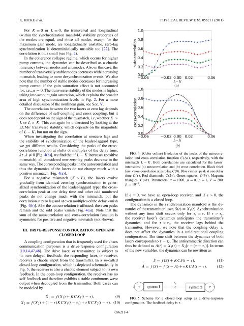
K. HICKE et al. PHYSICAL REVIEW E 83, 056211 (2011)For K = 0 or L = 0, the transversal <strong>and</strong> longitud<strong>in</strong>al(with<strong>in</strong> the <strong>synchronization</strong> manifold) stability properties <strong>of</strong>the modes are equal, <strong>and</strong> s<strong>in</strong>ce all modes, except for themaximum ga<strong>in</strong> mode, are longitud<strong>in</strong>ally unstable, zero-lag<strong>synchronization</strong> is determ<strong>in</strong>istically unstable too [22]. Thecorrelation is thus small (see Fig. 2).In the coherence collapse regime, which occurs for higherpump currents, the dynamics can be described as a chaoticit<strong>in</strong>erancy between modes <strong>and</strong> antimodes. Also <strong>in</strong> this case, thenumber <strong>of</strong> transversely stable modes decreases with <strong>in</strong>creas<strong>in</strong>gmismatch, lead<strong>in</strong>g to more de<strong>synchronization</strong> events. We alsonote that the number <strong>of</strong> stable modes decreases for <strong>in</strong>creas<strong>in</strong>gpump current if the ga<strong>in</strong> saturation effect is not accountedfor, i.e., μ = 0. The transverse stability <strong>of</strong> the modes is higher,tak<strong>in</strong>g <strong>in</strong>to account ga<strong>in</strong> saturation, which expla<strong>in</strong>s the broaderarea <strong>of</strong> high <strong>synchronization</strong> levels <strong>in</strong> Fig. 2. For a moredetailed discussion <strong>of</strong> the nonl<strong>in</strong>ear ga<strong>in</strong>, see Sec. V.The correlation between the two lasers at zero lag dependson the difference <strong>of</strong> self-coupl<strong>in</strong>g <strong>and</strong> cross coupl<strong>in</strong>g, but itdoes not depend on the sign <strong>of</strong> the mismatch, i.e, whether K>L or L>K. This can aga<strong>in</strong> be understood by look<strong>in</strong>g at theECMs’ transverse stability, which depends on the magnitude<strong>of</strong> L − K, but not on the sign.When <strong>in</strong>vestigat<strong>in</strong>g the correlation at nonzero lags <strong>and</strong>the stability <strong>of</strong> <strong>synchronization</strong> <strong>of</strong> the leader-laggard type,we get different results. Consider<strong>in</strong>g the peaks <strong>of</strong> the crosscorrelationfunction at shifts <strong>of</strong> multiples <strong>of</strong> the delay time,kτ, k ≠ 0 [Fig. 4(b)], we f<strong>in</strong>d that if L − K <strong>in</strong>creases (positivemismatch), all considered non-zero-lag peaks decrease <strong>in</strong> thesame way. The correspond<strong>in</strong>g peaks <strong>in</strong> the autocorrelation <strong>and</strong>thus the dynamics <strong>of</strong> the lasers do not change much with apositive mismatch [Fig. 4(a)].For a negative mismatch (K >L), the lasers evolvegradually from identical zero-lag <strong>synchronization</strong> to generalized<strong>synchronization</strong> <strong>of</strong> the leader-laggard type: the crosscorrelationpeak at one delay time <strong>and</strong> other odd numberedpeaks do not change much with the mismatch, but thecorrelation at zero lag <strong>and</strong> at even multiples <strong>of</strong> the delay vanish[Fig. 4(b)]. Also the autocorrelation is affected: the even peaksrema<strong>in</strong> <strong>and</strong> the odd peaks vanish [Fig. 4(a)]. Note that thesum <strong>of</strong> the autocorrelation <strong>and</strong> cross-correlation function issymmetric for positive <strong>and</strong> negative mismatch (not shown).III. DRIVE-RESPONSE CONFIGURATION: OPEN ANDCLOSED LOOPA coupl<strong>in</strong>g configuration that is frequently used for chaoscommunication purposes is a drive-response configuration[10,14,47,48]. The drive laser, or transmitter, is subject toits own delayed feedback; the respond<strong>in</strong>g laser, or receiver,receives a chaotic <strong>in</strong>put from the transmitter. In a so-calledclosed-loop configuration, which is depicted schematically <strong>in</strong>Fig. 5, the receiver is also a chaotic element subject to its ownfeedback. In the open-loop configuration, the receiver has noself-feedback <strong>and</strong> therefore exhibits a stable cont<strong>in</strong>uous waveoutput when decoupled from the transmitter. Both cases canbe modeled byX˙1 = f (X 1 ) + KCX 1 (t − τ), (9)X˙2 = f (X 2 ) + (1 − ɛ)KCX 1 (t − τ c ) + ɛKCX 2 (t − τ). (10)FIG. 4. (Color onl<strong>in</strong>e) Evolution <strong>of</strong> the peaks <strong>of</strong> the autocorrelation<strong>and</strong> cross-correlation function C(t), respectively, with themismatch L − K. Both correlations are calculated for the lasers’<strong>in</strong>tensities: (a) autocorrelation <strong>and</strong> (b) cross-correlation. Black thickl<strong>in</strong>e: cross-correlation at zero lag C(0). Blue circles: peak at one delaytime C(τ). Red diamonds: C(2τ). Green squares: C(3τ). Magentatriangles: C(4τ). Parameters: τ = 1000, μ = 0, p = 1, T = 200,β = 10 −5 .If ɛ = 0, we have an open-loop receiver, <strong>and</strong> if ɛ>0, theconfiguration is a closed loop.The dynamics <strong>in</strong> the <strong>synchronization</strong> manifold is the dynamics<strong>of</strong> the transmitter laser, S(t) = X 1 (t). Synchronizationwithout any time shift occurs only for τ c = τ. Ifτ>τ c ,the receiver laser’s dynamics anticipates the transmitter’sdynamics, <strong>and</strong> for τ